KR102010943B1 - Foreign object detection in wireless energy transfer systems - Google Patents
Foreign object detection in wireless energy transfer systems Download PDFInfo
- Publication number
- KR102010943B1 KR102010943B1 KR1020187020020A KR20187020020A KR102010943B1 KR 102010943 B1 KR102010943 B1 KR 102010943B1 KR 1020187020020 A KR1020187020020 A KR 1020187020020A KR 20187020020 A KR20187020020 A KR 20187020020A KR 102010943 B1 KR102010943 B1 KR 102010943B1
- Authority
- KR
- South Korea
- Prior art keywords
- debris
- magnetic field
- wireless energy
- fod
- source resonator
- Prior art date
Links
- 238000012546 transfer Methods 0.000 title claims abstract description 60
- 238000001514 detection method Methods 0.000 title claims abstract description 39
- 239000000463 material Substances 0.000 claims abstract description 5
- 238000000034 method Methods 0.000 claims description 44
- 230000005540 biological transmission Effects 0.000 claims description 11
- 230000000116 mitigating effect Effects 0.000 description 19
- 239000004020 conductor Substances 0.000 description 8
- 230000004907 flux Effects 0.000 description 8
- 230000008859 change Effects 0.000 description 6
- 229940112822 chewing gum Drugs 0.000 description 6
- 235000015218 chewing gum Nutrition 0.000 description 6
- 238000013461 design Methods 0.000 description 6
- 238000012545 processing Methods 0.000 description 6
- 230000035945 sensitivity Effects 0.000 description 5
- 238000003491 array Methods 0.000 description 4
- 239000011888 foil Substances 0.000 description 4
- 239000002184 metal Substances 0.000 description 4
- 230000006870 function Effects 0.000 description 3
- 230000008569 process Effects 0.000 description 3
- 238000005070 sampling Methods 0.000 description 3
- XLYOFNOQVPJJNP-UHFFFAOYSA-N water Substances O XLYOFNOQVPJJNP-UHFFFAOYSA-N 0.000 description 3
- 230000001143 conditioned effect Effects 0.000 description 2
- 238000002405 diagnostic procedure Methods 0.000 description 2
- 238000010586 diagram Methods 0.000 description 2
- 235000013305 food Nutrition 0.000 description 2
- 230000005484 gravity Effects 0.000 description 2
- 238000005259 measurement Methods 0.000 description 2
- 238000013021 overheating Methods 0.000 description 2
- 230000002285 radioactive effect Effects 0.000 description 2
- 239000000126 substance Substances 0.000 description 2
- 241000282326 Felis catus Species 0.000 description 1
- 241000208125 Nicotiana Species 0.000 description 1
- 235000002637 Nicotiana tabacum Nutrition 0.000 description 1
- 206010037660 Pyrexia Diseases 0.000 description 1
- CDBYLPFSWZWCQE-UHFFFAOYSA-L Sodium Carbonate Chemical compound [Na+].[Na+].[O-]C([O-])=O CDBYLPFSWZWCQE-UHFFFAOYSA-L 0.000 description 1
- 229910000831 Steel Inorganic materials 0.000 description 1
- 235000019504 cigarettes Nutrition 0.000 description 1
- 238000004891 communication Methods 0.000 description 1
- 230000000295 complement effect Effects 0.000 description 1
- 230000003750 conditioning effect Effects 0.000 description 1
- 238000012790 confirmation Methods 0.000 description 1
- 230000001419 dependent effect Effects 0.000 description 1
- 239000000428 dust Substances 0.000 description 1
- 230000000694 effects Effects 0.000 description 1
- 230000005684 electric field Effects 0.000 description 1
- 230000005672 electromagnetic field Effects 0.000 description 1
- 238000005516 engineering process Methods 0.000 description 1
- 235000013410 fast food Nutrition 0.000 description 1
- 238000001914 filtration Methods 0.000 description 1
- 239000004519 grease Substances 0.000 description 1
- 235000015220 hamburgers Nutrition 0.000 description 1
- 238000010438 heat treatment Methods 0.000 description 1
- 230000001939 inductive effect Effects 0.000 description 1
- 230000002452 interceptive effect Effects 0.000 description 1
- 239000000696 magnetic material Substances 0.000 description 1
- 239000000203 mixture Substances 0.000 description 1
- 238000012544 monitoring process Methods 0.000 description 1
- 230000005405 multipole Effects 0.000 description 1
- 239000003921 oil Substances 0.000 description 1
- 239000011368 organic material Substances 0.000 description 1
- 230000010355 oscillation Effects 0.000 description 1
- 230000008447 perception Effects 0.000 description 1
- 230000010363 phase shift Effects 0.000 description 1
- 239000012857 radioactive material Substances 0.000 description 1
- 230000001105 regulatory effect Effects 0.000 description 1
- 239000004576 sand Substances 0.000 description 1
- 238000004513 sizing Methods 0.000 description 1
- 239000010959 steel Substances 0.000 description 1
- 210000002268 wool Anatomy 0.000 description 1
Images


Classifications
-
- H—ELECTRICITY
- H02—GENERATION; CONVERSION OR DISTRIBUTION OF ELECTRIC POWER
- H02J—CIRCUIT ARRANGEMENTS OR SYSTEMS FOR SUPPLYING OR DISTRIBUTING ELECTRIC POWER; SYSTEMS FOR STORING ELECTRIC ENERGY
- H02J50/00—Circuit arrangements or systems for wireless supply or distribution of electric power
- H02J50/60—Circuit arrangements or systems for wireless supply or distribution of electric power responsive to the presence of foreign objects, e.g. detection of living beings
-
- B—PERFORMING OPERATIONS; TRANSPORTING
- B60—VEHICLES IN GENERAL
- B60L—PROPULSION OF ELECTRICALLY-PROPELLED VEHICLES; SUPPLYING ELECTRIC POWER FOR AUXILIARY EQUIPMENT OF ELECTRICALLY-PROPELLED VEHICLES; ELECTRODYNAMIC BRAKE SYSTEMS FOR VEHICLES IN GENERAL; MAGNETIC SUSPENSION OR LEVITATION FOR VEHICLES; MONITORING OPERATING VARIABLES OF ELECTRICALLY-PROPELLED VEHICLES; ELECTRIC SAFETY DEVICES FOR ELECTRICALLY-PROPELLED VEHICLES
- B60L53/00—Methods of charging batteries, specially adapted for electric vehicles; Charging stations or on-board charging equipment therefor; Exchange of energy storage elements in electric vehicles
- B60L53/10—Methods of charging batteries, specially adapted for electric vehicles; Charging stations or on-board charging equipment therefor; Exchange of energy storage elements in electric vehicles characterised by the energy transfer between the charging station and the vehicle
- B60L53/12—Inductive energy transfer
- B60L53/124—Detection or removal of foreign bodies
-
- B—PERFORMING OPERATIONS; TRANSPORTING
- B60—VEHICLES IN GENERAL
- B60L—PROPULSION OF ELECTRICALLY-PROPELLED VEHICLES; SUPPLYING ELECTRIC POWER FOR AUXILIARY EQUIPMENT OF ELECTRICALLY-PROPELLED VEHICLES; ELECTRODYNAMIC BRAKE SYSTEMS FOR VEHICLES IN GENERAL; MAGNETIC SUSPENSION OR LEVITATION FOR VEHICLES; MONITORING OPERATING VARIABLES OF ELECTRICALLY-PROPELLED VEHICLES; ELECTRIC SAFETY DEVICES FOR ELECTRICALLY-PROPELLED VEHICLES
- B60L53/00—Methods of charging batteries, specially adapted for electric vehicles; Charging stations or on-board charging equipment therefor; Exchange of energy storage elements in electric vehicles
- B60L53/10—Methods of charging batteries, specially adapted for electric vehicles; Charging stations or on-board charging equipment therefor; Exchange of energy storage elements in electric vehicles characterised by the energy transfer between the charging station and the vehicle
- B60L53/12—Inductive energy transfer
-
- G—PHYSICS
- G01—MEASURING; TESTING
- G01R—MEASURING ELECTRIC VARIABLES; MEASURING MAGNETIC VARIABLES
- G01R33/00—Arrangements or instruments for measuring magnetic variables
- G01R33/02—Measuring direction or magnitude of magnetic fields or magnetic flux
- G01R33/10—Plotting field distribution ; Measuring field distribution
-
- G—PHYSICS
- G01—MEASURING; TESTING
- G01V—GEOPHYSICS; GRAVITATIONAL MEASUREMENTS; DETECTING MASSES OR OBJECTS; TAGS
- G01V3/00—Electric or magnetic prospecting or detecting; Measuring magnetic field characteristics of the earth, e.g. declination, deviation
- G01V3/08—Electric or magnetic prospecting or detecting; Measuring magnetic field characteristics of the earth, e.g. declination, deviation operating with magnetic or electric fields produced or modified by objects or geological structures or by detecting devices
- G01V3/10—Electric or magnetic prospecting or detecting; Measuring magnetic field characteristics of the earth, e.g. declination, deviation operating with magnetic or electric fields produced or modified by objects or geological structures or by detecting devices using induction coils
-
- H02J5/005—
-
- H—ELECTRICITY
- H02—GENERATION; CONVERSION OR DISTRIBUTION OF ELECTRIC POWER
- H02J—CIRCUIT ARRANGEMENTS OR SYSTEMS FOR SUPPLYING OR DISTRIBUTING ELECTRIC POWER; SYSTEMS FOR STORING ELECTRIC ENERGY
- H02J50/00—Circuit arrangements or systems for wireless supply or distribution of electric power
- H02J50/10—Circuit arrangements or systems for wireless supply or distribution of electric power using inductive coupling
- H02J50/12—Circuit arrangements or systems for wireless supply or distribution of electric power using inductive coupling of the resonant type
-
- H—ELECTRICITY
- H02—GENERATION; CONVERSION OR DISTRIBUTION OF ELECTRIC POWER
- H02J—CIRCUIT ARRANGEMENTS OR SYSTEMS FOR SUPPLYING OR DISTRIBUTING ELECTRIC POWER; SYSTEMS FOR STORING ELECTRIC ENERGY
- H02J50/00—Circuit arrangements or systems for wireless supply or distribution of electric power
- H02J50/40—Circuit arrangements or systems for wireless supply or distribution of electric power using two or more transmitting or receiving devices
-
- H—ELECTRICITY
- H02—GENERATION; CONVERSION OR DISTRIBUTION OF ELECTRIC POWER
- H02J—CIRCUIT ARRANGEMENTS OR SYSTEMS FOR SUPPLYING OR DISTRIBUTING ELECTRIC POWER; SYSTEMS FOR STORING ELECTRIC ENERGY
- H02J50/00—Circuit arrangements or systems for wireless supply or distribution of electric power
- H02J50/90—Circuit arrangements or systems for wireless supply or distribution of electric power involving detection or optimisation of position, e.g. alignment
-
- H02J7/025—
-
- B—PERFORMING OPERATIONS; TRANSPORTING
- B60—VEHICLES IN GENERAL
- B60Y—INDEXING SCHEME RELATING TO ASPECTS CROSS-CUTTING VEHICLE TECHNOLOGY
- B60Y2200/00—Type of vehicle
- B60Y2200/90—Vehicles comprising electric prime movers
- B60Y2200/91—Electric vehicles
-
- H—ELECTRICITY
- H01—ELECTRIC ELEMENTS
- H01F—MAGNETS; INDUCTANCES; TRANSFORMERS; SELECTION OF MATERIALS FOR THEIR MAGNETIC PROPERTIES
- H01F27/00—Details of transformers or inductances, in general
- H01F27/28—Coils; Windings; Conductive connections
- H01F27/2804—Printed windings
-
- H—ELECTRICITY
- H01—ELECTRIC ELEMENTS
- H01F—MAGNETS; INDUCTANCES; TRANSFORMERS; SELECTION OF MATERIALS FOR THEIR MAGNETIC PROPERTIES
- H01F38/00—Adaptations of transformers or inductances for specific applications or functions
- H01F38/14—Inductive couplings
-
- Y—GENERAL TAGGING OF NEW TECHNOLOGICAL DEVELOPMENTS; GENERAL TAGGING OF CROSS-SECTIONAL TECHNOLOGIES SPANNING OVER SEVERAL SECTIONS OF THE IPC; TECHNICAL SUBJECTS COVERED BY FORMER USPC CROSS-REFERENCE ART COLLECTIONS [XRACs] AND DIGESTS
- Y02—TECHNOLOGIES OR APPLICATIONS FOR MITIGATION OR ADAPTATION AGAINST CLIMATE CHANGE
- Y02T—CLIMATE CHANGE MITIGATION TECHNOLOGIES RELATED TO TRANSPORTATION
- Y02T10/00—Road transport of goods or passengers
- Y02T10/60—Other road transportation technologies with climate change mitigation effect
- Y02T10/70—Energy storage systems for electromobility, e.g. batteries
-
- Y02T10/7005—
-
- Y—GENERAL TAGGING OF NEW TECHNOLOGICAL DEVELOPMENTS; GENERAL TAGGING OF CROSS-SECTIONAL TECHNOLOGIES SPANNING OVER SEVERAL SECTIONS OF THE IPC; TECHNICAL SUBJECTS COVERED BY FORMER USPC CROSS-REFERENCE ART COLLECTIONS [XRACs] AND DIGESTS
- Y02—TECHNOLOGIES OR APPLICATIONS FOR MITIGATION OR ADAPTATION AGAINST CLIMATE CHANGE
- Y02T—CLIMATE CHANGE MITIGATION TECHNOLOGIES RELATED TO TRANSPORTATION
- Y02T10/00—Road transport of goods or passengers
- Y02T10/60—Other road transportation technologies with climate change mitigation effect
- Y02T10/7072—Electromobility specific charging systems or methods for batteries, ultracapacitors, supercapacitors or double-layer capacitors
-
- Y—GENERAL TAGGING OF NEW TECHNOLOGICAL DEVELOPMENTS; GENERAL TAGGING OF CROSS-SECTIONAL TECHNOLOGIES SPANNING OVER SEVERAL SECTIONS OF THE IPC; TECHNICAL SUBJECTS COVERED BY FORMER USPC CROSS-REFERENCE ART COLLECTIONS [XRACs] AND DIGESTS
- Y02—TECHNOLOGIES OR APPLICATIONS FOR MITIGATION OR ADAPTATION AGAINST CLIMATE CHANGE
- Y02T—CLIMATE CHANGE MITIGATION TECHNOLOGIES RELATED TO TRANSPORTATION
- Y02T90/00—Enabling technologies or technologies with a potential or indirect contribution to GHG emissions mitigation
- Y02T90/10—Technologies relating to charging of electric vehicles
- Y02T90/12—Electric charging stations
-
- Y—GENERAL TAGGING OF NEW TECHNOLOGICAL DEVELOPMENTS; GENERAL TAGGING OF CROSS-SECTIONAL TECHNOLOGIES SPANNING OVER SEVERAL SECTIONS OF THE IPC; TECHNICAL SUBJECTS COVERED BY FORMER USPC CROSS-REFERENCE ART COLLECTIONS [XRACs] AND DIGESTS
- Y02—TECHNOLOGIES OR APPLICATIONS FOR MITIGATION OR ADAPTATION AGAINST CLIMATE CHANGE
- Y02T—CLIMATE CHANGE MITIGATION TECHNOLOGIES RELATED TO TRANSPORTATION
- Y02T90/00—Enabling technologies or technologies with a potential or indirect contribution to GHG emissions mitigation
- Y02T90/10—Technologies relating to charging of electric vehicles
- Y02T90/14—Plug-in electric vehicles
Abstract
무선 에너지 전송 시스템은 이물질 잔해 검출 시스템을 포함한다. 이 시스템은 진동하는 자기장을 생성하도록 구성되는 적어도 하나의 무선 에너지 전송 소스를 포함한다. 이물질 잔해는 진동하는 자기장 내에 위치된 적어도 하나의 자기장 구배측정기에 의하여 검출될 수도 있다. 적어도 하나의 자기장 구배측정기의 전압은 판독 회로부 및 피드백 루프를 사용하여 측정될 수도 있고 구배측정기로부터의 판독치는 무선 에너지 소스의 파라미터를 제어하기 위하여 사용될 수도 있다. The wireless energy transfer system includes a debris detection system . The system includes at least one wireless energy transfer source configured to generate a vibrating magnetic field . Foreign material debris may be detected by at least one magnetic field gradient meter located within a vibrating magnetic field . The voltage of at least one magnetic field gradient meter may be measured using readout circuitry and a feedback loop and readings from the gradientmeter may be used to control the parameters of the wireless energy source .
Description
관련 출원들에의 상호-참조Cross-Reference to Related Applications
이 출원서는 2011년 9월 9일에 출원된 미국 가출원 번호 제 61/532,785 호에 대한 우선권을 주장한다.This application claims priority to US Provisional Application No. 61 / 532,785, filed September 9, 2011.
분야:Field:
본 개시물은 무선 에너지 전송 및 무선 전력 송신 시스템에서의 이물질 잔해(foreign object debris; FOD)를 검출하는 방법에 관련된다.The present disclosure relates to a method for detecting foreign object debris (FOD) in wireless energy transmission and wireless power transmission systems.
관련 기술의 설명Description of the related technology
에너지 또는 전력은, 예를 들어 모두 동일인 소유인, 2010 년 5 월 6 일에 US 2010/010909445 호로서 공개되고 발명의 명칭이 "Wireless Energy Transfer Systems"인 미국 특허 출원 제 12/613,686 호, 2010 년 12 월 9 일에 2010/0308939 로서 공개되고 발명의 명칭이 "Integrated Resonator-Shield Structures"인 미국 특허 출원 제 12/860,375 호, 2012 년 3 월 15 일에 2012/0062345 로서 공개되고 발명의 명칭이 "Low Resistance Electrical Conductor"인 미국 특허 출원 제 13/222,915 호, 공개되며 발명의 명칭이 "Multi-Resonator Wireless Energy Transfer for Lighting"인 미국 특허 출원 제 13/283,811 호에서 구체적으로 기술되는 바와 같은 다양한 공지된 방사성 또는 원거리장(far-field), 및 비-방사성 또는 근거리장 기법들을 사용하여 무선으로 전송될 수도 있으며, 이들의 콘텐츠는 원용에 의하여 통합된다. Energy or power is disclosed, for example, in US 2010/010909445 on May 6, 2010, all owned by the same and in US Patent Application No. 12 / 613,686 entitled “Wireless Energy Transfer Systems”, 2010 12 US patent application Ser. No. 12 / 860,375, published on March 9 as 2010/0308939 and entitled "Integrated Resonator-Shield Structures," published March 15, 2012, as 2012/0062345, and entitled "Low." A variety of known radioactive materials as disclosed in US Patent Application No. 13 / 222,915, entitled Resistance Electrical Conductor, and specifically disclosed in US Patent Application No. 13 / 283,811, entitled "Multi-Resonator Wireless Energy Transfer for Lighting." Or may be transmitted wirelessly using far-field, and non-radioactive or near-field techniques, the contents of which are integrated by far .
두 개의 커플링된 공진기들 사이의 진동하는 자기장에 의존하는 무선 충전 시스템은 효율적이고, 비-방사성이며, 안전할 수 있다. 공진기들 사이에 삽입되는 비-자기적 및/또는 비-금속성 오브젝트는 무선 에너지 전송을 위하여 사용되는 자기장과 실질적으로 상호작용한다. 몇 가지 실시예들에서, 무선 전력 전송 시스템의 사용자는 이러한 "이물질"의 존재를 검출하려고 원할 수도 있으며 무선 전력 전송 시스템을 제어, 턴 다운, 턴 오프, 알람발생 등을 하기를 원할 수도 있다. 공진기 들 사이에 삽입된 금속성 오브젝트 및/또는 다른 오브젝트들은 금속성 및/또는 다른 오브젝트가 무선 에너지 전송에 요동을 일으키고(perturb) 및/또는 크게 온도가 올라가게 하는 방식으로 무선 전력 전송 시스템의 자기장과 상호작용할 수도 있다. 몇 가지 실시예들에서, 무선 전력 전송 시스템의 사용자는 이러한 "이물질"의 존재를 검출하려고 원할 수도 있으며 무선 전력 전송 시스템을 제어, 턴 다운, 턴 오프, 알람발생 등을 하기를 원할 수도 있다.Wireless charging systems that rely on a vibrating magnetic field between two coupled resonators can be efficient, non-radioactive and safe . Non-magnetic and / or non-metallic objects inserted between the resonators substantially interact with the magnetic field used for wireless energy transfer . In some embodiments, a user of a wireless power transfer system may wish to detect the presence of such “foreign” and may want to control, turn down, turn off, alarm, etc. the wireless power transfer system . Metallic objects and / or other objects inserted between the resonators interact with the magnetic field of the wireless power transfer system in such a way that the metallic and / or other objects perturb the wireless energy transfer and / or cause the temperature to rise significantly. It may work . In some embodiments, a user of a wireless power transfer system may wish to detect the presence of such “foreign” and may want to control, turn down, turn off, alarm, etc. the wireless power transfer system.
무선 전력 송신 시스템의 근방에 위치된 이물질 잔해(Foreign Object Debris; FOD)는 양성(benign)일 수 있고 및/또는 양성 방식으로 에너지 전송을 위하여 사용되는 필드와 상호작용할 수도 있다. 양성 FOD는 먼지, 모래, 나뭇잎, 나뭇가지, 눈, 구리스(grease), 오일, 물, 및 저-주파수 자기장과는 크게 상호작용하지 않을 수도 있는 다른 물질을 포함할 수도 있다. 실시예들에서, FOD는 양성 방식으로 무선 에너지 전송을 위하여 사용되는 필드와 상호작용할 수도 있는 오브젝트를 포함할 수도 있는데, 하지만 이것은 지각된 위험, 또는 주의력의 양호함 때문에 무선 전송 시스템의 공진기에 매우 근접한 지역으로부터 제한될 수도 있다. 이러한 타입의 FOD의 공통적인 예는 예를 들어 무선 EV 충전 시스템의 코일들 사이에서 잠을 자려고 할 수도 있는 고양이이다. 실시예들에서, 몇몇 FOD는 에너지 전송을 위하여 사용되는 공진기의 특징에 요동을 일으키는 방식으로 자기장과 상호작용할 수도 있고, 에너지 전송을 위하여 사용되는 자기장을 차폐하거나 감소시킬 수도 있으며, 또는 화재 및 또는 화재의 위험을 발생시킬 수도 있다. 일부 애플리케이션에서 고-전력 충전 도중에 가연성 금속성 오브젝트가 발화하기에 충분하게 되는 것을 방지하기 위하여 특별한 주의가 필요할 수도 있다. 몇몇 금속성 오브젝트들은 가열되고 이것이 여전히 뜨거운 동안에 이것을 집으려는 사람에게 화상을 입히거나 불쾌감을 주기에 충분한 열용량을 가질 수 있다. 예들은 툴, 코일, 금속 조각, 소다 캔, 강철 울(wool), 음식(씹는 검, 버거 등) 래퍼(wrapper), 금속 호일이 있는 담배갑, 및 기타 등등을 포함한다. Foreign Object Debris (FOD) located near the wireless power transmission system may be positive and / or interact with the field used for energy transmission in a positive manner . A positive FOD may include dust, sand, leaves, twigs, snow, grease, oil, water, and other substances that may not interact significantly with low-frequency magnetic fields . In embodiments, the FOD may comprise an object that may interact with the field used for wireless energy transfer in a positive manner, but this is very close to the resonator of the wireless transmission system because of perceived risk or good attention. May be restricted from region . A common example of this type of FOD is a cat that may want to sleep between coils of a wireless EV charging system, for example . In embodiments, some FODs may interact with the magnetic field in a manner that causes fluctuations in the characteristics of the resonator used for energy transfer, shield or reduce the magnetic field used for energy transfer, or fire and / or fire It may also create a risk . In some applications, special care may be required to prevent flammable metallic objects from becoming sufficient to ignite during high-power charging . Some metallic objects may have enough heat capacity to heat up and burn or offend the person trying to pick it up while it is still hot . Examples include tools, coils, scraps of metal, soda cans, steel wool, food (chewing gum, burgers, etc.) wrappers, cigarette packs with metal foil, and the like .
따라서 무선 에너지 전송 시스템 근방에 있는 FOD의 효과를 검출하거나 완화시키기 위한 방법 및 디자인이 요구된다. Therefore, a need exists for a method and design for detecting or mitigating the effects of FOD in the vicinity of wireless energy transfer systems .
예시적이고 비한정적인 실시예에 따르면, 이물질 잔해 검출 시스템은 측정 무선 에너지 전송 시스템의 공진기 주위의 자기장에 있는 동요를 자기장 센서 및/또는 구배측정기를 사용하여 측정할 수도 있다. 센서 및/또는 구배측정기는 무선 에너지 전송 시스템의 자기장 내에 위치될 수도 있다. 센서 및/또는 구배측정기는 와이어의 루프 및/또는 루프를 형성하는 인쇄된 도체 트레이스, 8자형 루프, 및/또는 자신의 표면을 관통하는 자기적 플럭스의 양에 비례하는 전기 신호를 생성하는 하나의 루프 또는 다중 루프를 포함하는 구조를 포함할 수도 있다. 루프 및/또는 루프들은 고-입력-임피던스 판독 회로부에 연결될 수도 있다. 판독 회로부는 루프 내의 전압 및/또는 전류 및/또는 전압 및/또는 전류의 상대적인 위상을 측정할 수도 있다. 실시예들에서 시스템은 루프들의 다중층을 포함하여 FOD의 검출 확률을 증가시킬 수도 있다. 실시예들에서, 루프는 공진기의 동요된 품질 인자, 에너지 전송의 효율, 전송된 전력의 양, 시스템에 의하여 생성된 열 및 기타 등등과 같은 무선 전력 전송 시스템의 특징에 크게 영향을 미치지 않고 동작하도록 설계될 수도 있다.According to an exemplary and non-limiting embodiment, the debris detection system may measure fluctuations in the magnetic field around the resonator of the measuring wireless energy transfer system using a magnetic field sensor and / or a gradient meter . The sensor and / or gradient meter may be located in a magnetic field of the wireless energy transfer system . Sensors and / or gradiometers generate one electrical signal that is proportional to the amount of printed conductor traces, eight-shaped loops, and / or magnetic flux that penetrates its surface forming loops and / or loops of wires. It may also include structures that contain loops or multiple loops . The loop and / or loops may be connected to a high-input impedance readout circuitry . The readout circuitry may measure the relative phase of the voltage and / or current and / or voltage and / or current in the loop . In embodiments the system may include multiple layers of loops to increase the detection probability of the FOD . In embodiments, the loop is designed to operate without significantly affecting the characteristics of the wireless power transfer system, such as the fluctuating quality factor of the resonator, the efficiency of energy transfer, the amount of power transmitted, the heat generated by the system, and the like. It may be designed.
예시적이고 비한정적인 실시예에 따르면, 이물질 잔해 검출 시스템을 포함할 수도 있는 무선 에너지 전송 시스템이 제공된다. 이 시스템은 진동하는 자기장을 생성하도록 구성되는 적어도 하나의 무선 에너지 전송 소스를 포함할 수도 있다. 이물질 잔해는 진동하는 자기장 내에 위치된 자기장 구배측정기에 의하여 검출될 수도 있다. 구배측정기의 전압 및/또는 전류는 판독 회로부 및 피드백 루프를 사용하여 측정될 수도 있고 구배측정기로부터의 판독치는 무선 에너지 소스의 파라미터를 제어하기 위하여 사용될 수도 있다. According to an exemplary and non-limiting embodiment, a wireless energy transfer system is provided that may include a foreign substance debris detection system . The system may include at least one wireless energy transfer source configured to generate a vibrating magnetic field . Foreign material debris may be detected by a magnetic gradient meter located within a vibrating magnetic field . The voltage and / or current of the gradient meter may be measured using readout circuitry and a feedback loop and readings from the gradientmeter may be used to control the parameters of the wireless energy source .
도 1 은 수동 FOD 완화를 제공하는 공진기 커버가 있는 공진기의 측면도를 도시한다.
도 2 는 각각의 필드 센서로서 사용될 수도 있으며 두 개의 개개의 필드 센서들에 의한 자기적 플럭스 캡쳐에서의 차분을 감지하는 구배측정기 내로 패셔닝될 수도 있는 와이어의 두 개의 루프를 도시한다.
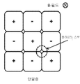
도 3a 는 대항하는 자기적 쌍극자를 가지도록 정렬되는 두 개의 작은 도체 루프의 2-로브 구성(이러한 구조는 자기적 사극자(magnetic quadrupole)라고 지칭될 수도 있음)을 도시한다; 도 3b 는 정렬된 자기적 사극자의 4-로브 구성을 도시한다; 도 3c 는 대항된 사극자의 4-로브 구성으로서 흔히 팔극자(octupole)라고 불리는 것을 도시한다; 그리고 도 3d 는 선형 차원에서 연장하는 4-로브 구성을 도시한다. "+" 및 "-" 부호들은 상대적 참조 프레임에서, 각각의 루프의 자기적 쌍극자의 방향을 표시한다.
도 4a 는 높은 영역-충진 인자를 획득하기 위한 정방형 형상을 가진 루프를 포함하는 FOD 검출기 어레이를 도시한다; 그리고 도 4b 는 두 개의 오프셋 어레이가 있는 일 실시예로서 블라인드 스팟을 제거하기 위하여 사용될 수도 있는 배치구성을 도시한다.
도 5 는 판독 회로에 접속된 FOD 검출기를 도시한다.
도 6 은 판독 회로부에 접속된 FOD 검출기들의 어레이를 도시한다.
도 7 은 판독 회로부 및 동기화 루프에 접속된 FOD 검출기들의 어레이를 도시한다.
도 8 은 FOD 검출기 루프들의 일 예시적인 실시예를 도시한다.
도 9a 내지 도 9c 는 8자형 구배측정기 센서로부터의 예시적인 전압 측정 곡선들을 도시한다.
도 10 은 예시적인 EV 충전기 시스템의 블록도를 도시한다. 1 shows a side view of a resonator with a resonator cover providing passive FOD mitigation.
FIG. 2 shows two loops of wire that may be used as each field sensor and may be fashioned into a gradient meter that detects a difference in magnetic flux capture by two separate field sensors.
FIG. 3A shows a two-lobe configuration of two small conductor loops arranged to have opposing magnetic dipoles (this structure may be referred to as a magnetic quadrupole); 3b shows a four-lobe configuration of aligned magnetic quadrupoles; FIG. 3C shows what is often called the octupole as a four-lobe configuration of opposed quadrupoles; And FIG. 3D shows a four-lobe configuration extending in a linear dimension . The "+" and "-" signs indicate the direction of the magnetic dipole of each loop in the relative reference frame.
4A shows an FOD detector array comprising a loop having a square shape to obtain a high region-fill factor; And FIG. 4B illustrates an arrangement that may be used to remove blind spots as an embodiment with two offset arrays.
5 shows a FOD detector connected to a read circuit.
6 shows an array of FOD detectors connected to read circuitry.
7 shows an array of FOD detectors connected to the readout circuitry and the synchronization loop.
8 shows an exemplary embodiment of FOD detector loops.
9A-9C show exemplary voltage measurement curves from an eight-dimensional gradient meter sensor.
10 shows a block diagram of an example EV charger system .
FOD 위험을 완화시키기 위한 방법은 수동 완화 기법 및 능동 완화 기법으로 범주화될 수 있다. 수동 완화 기법은 FOD가 높은 자기장의 지역 내에 진입하거나 거기에 머무는 것을 방지하기 위하여 사용될 수도 있다. 수동 완화 기법은 FOD가 자기장과 위험하게 상호작용할 우도를 낮출 수도 있다. 능동 완화 기법은 FOD의 존재를 검출하고 이에 대응하기 위하여 사용될 수도 있다. Methods for mitigating FOD risks can be categorized into passive mitigation techniques and active mitigation techniques . Passive mitigation techniques may be used to prevent the FOD from entering or staying in areas of high magnetic fields . Passive mitigation techniques may lower the likelihood that the FOD will interact dangerously with the magnetic field . Active mitigation techniques may be used to detect and respond to the presence of FOD .
수동 완화 기법Manual Mitigation Techniques
수동 완화 기법은 FOD가 공진기들 사이의 지역 또는 높은 자기장의 특정한 지역에 진입하는 것을 방지하고, 이를 통하여 FOD의 자기장과의 상호작용을 방지하도록 사용될 수도 있다. Passive mitigation techniques may be used to prevent the FOD from entering areas between resonators or specific areas of high magnetic fields, thereby preventing the FOD from interacting with the magnetic field .
추가적인 예시적 실시예를 통하여, 무선 전력 전송 시스템의 공진기 커버의 디자인이 수동 FOD 완화 기법을 제공할 수도 있다. 실시예들에서, 소스 및/또는 디바이스 및/또는 리피터 공진기의 엔클로저는 FOD가 자기장이 매우 클 수도 있는 공진기 및/또는 공진기 코일의 영역에 근접하게 접근하는 것을 방지하도록 성형될 수도 있다. 공진기 엔클로저는 만곡되거나, 각지도록 설계되거나, 또는 커버 상의 임의의 FOD가 커버 밖으로 구르고 공진기 및/또는 높은 자기장으로부터 멀어지게 밀어내도록 성형될 수도 있다. 공진기 엔클로저는 중력이 오브젝트를 공진기로부터 멀리 끌어당기도록 성형되거나 위치될 수도 있다. 다른 실시예들에서 공진기의 엔클로저 및 포지션은 FOD를 멀리 이동시키기 위하여 다른 자연적이거나 편재하는(omnipresent) 힘을 사용하도록 설계될 수도 있다. 예를 들어, 물 흐름, 바람, 진동 등의 힘이 FOD가 공진기 주위의 원치 않는 지역에서 축적하거나 머무는 것을 방지하기 위하여 사용될 수도 있다. 실시예들에서, 공진기는 지면과 실질적으로 수직이 되도록 정렬됨으로써, 오브젝트들이 공진기 상에 자연적으로 정지하거나 축적하지 않도록 할 수도 있다. 실시예들에서, 공진기 엔클로저는 FOD 및 공진기 컴포넌트 사이의 최소 거리를 허용하는 금지 존을 포함할 수도 있다. 금지 존은 금지 존 외부의 필드가 안전성 또는 성능 문제들을 야기하지 않을 만큼 충분히 작도록 보장하기 위하여 충분히 클 수도 있다. Through additional exemplary embodiments, the design of the resonator cover of the wireless power transfer system may provide a passive FOD mitigation technique . In embodiments, the enclosure of the source and / or device and / or repeater resonator may be shaped to prevent the FOD from approaching an area of the resonator and / or resonator coil where the magnetic field may be very large . The resonator enclosure may be curved, angled, or shaped such that any FOD on the cover rolls out of the cover and pushes it away from the resonator and / or high magnetic field . The resonator enclosure may be shaped or positioned such that gravity pulls the object away from the resonator . In other embodiments the enclosure and position of the resonator may be designed to use other natural or omnipresent forces to move the FOD away . For example, forces such as water flow, wind, vibration, etc. may be used to prevent the FOD from accumulating or staying in unwanted areas around the resonator . In embodiments, the resonator may be aligned to be substantially perpendicular to the ground, such that objects do not naturally stop or accumulate on the resonator . In embodiments, the resonator enclosure may include a forbidden zone that allows a minimum distance between the FOD and the resonator component . The forbidden zone may be large enough to ensure that fields outside the forbidden zone are small enough to not cause safety or performance problems .
어느 정도의 수동 FOD 보호를 제공하는 일 예시적인 공진기 커버가 도 1 에 도시된다. 무선 전력 전송 시스템의 자기적 공진기(104)는 성형된 커버(102)에 의하여 둘러싸이거나 밀폐되거나 또는 그 아래에 배치될 수도 있다. 커버(102)는 FOD(106)가 중력의 힘에 기인하여 커버(102) 아래로 굴러가게 하도록 성형될 수도 있다. 커버(102)의 형상은 임의의 FOD를 공진기의 측면으로 및/또는 자기장의 크기가 FOD의 가열에 기인하여 위험 상태를 야기하기에 충분히 큰 공진기를 둘러싸는 지역으로부터 멀리 보냄으로써, FOD(106)가 커버(102)의 상단에 및/또는 공진기(104)의 근방에 축적하는 것을 방지할 수도 있다. 실시예들에서, FOD는 높은 필드 지역으로부터 충분히 멀리 보내져서 더 이상 필드에 의하여 가열되고 및/또는 점화되는 위험을 가지지 않게 할 수도 있다.One exemplary resonator cover that provides some passive FOD protection is shown in FIG. 1 . The
다른 예시적이고 비한정적인 실시예에서, 수동 FOD 기법은 원하는 한계 아래의 무선 전력 교환의 지역 내의 임의의 장소에서 최대 자기장 밀도를 감소시키기 위하여 공진기 및/또는 공진기 컴포넌트를 크기결정하는 것을 포함할 수도 있다. 실시예들에서, 상대적으로 큰 공진기 코일이 FOD 위험의 서브세트를 완화시키기 위하여 사용될 수도 있다. 전력 전송의 고정된 레벨에 대하여, 더 큰 공진기 코일의 사용이, 어떤 양의 전력을 무선으로 전송하기 위하여 요구되는 단위 면적당 자기장 세기를 감소시키기 위하여 사용될 수도 있다. 예를 들어, 소스에 의하여 생성된 최대 자기장 세기는 발열 또는 다른 위험이 발생하는 것으로 알려진 임계 아래로 감소될 수도 있다. 수동 완화 기법이 언제나 가능하거나 실용적이거나 충분한 것은 아닐 수도 있다. 예를 들어, 공진기 사이즈를 크게 함으로써 FOD 위험을 감소시키는 것은 시스템 비용 제한에 기인하거나 공진기를 특정 크기의 시스템 내에 통합시키고자 하는 희망에 기인하여 실용적이지 않을 수도 있다. 그러나, 완전히 수동적인 기법이 가능하거나 실용적이거나 및/또는 충분하지 않을 수도 있는 애플리케이션에서도, 수동 완화 기법은 FOD 위험을 적어도 부분적으로 감소시키기 위하여 사용될 수도 있고 능동 완화 기법에 대하여 상보적일 수도 있다.In another illustrative and non-limiting embodiment, the passive FOD technique may include sizing the resonator and / or resonator component to reduce the maximum magnetic field density at any place within the area of wireless power exchange below the desired limit. . In embodiments, a relatively large resonator coil may be used to mitigate a subset of the FOD risk . For a fixed level of power transmission, the use of larger resonator coils may be used to reduce the magnetic field strength per unit area required to transmit some amount of power wirelessly . For example, the maximum magnetic field strength generated by the source may be reduced below a threshold known to cause exothermic or other hazards . Manual mitigation techniques may not always be possible, practical or sufficient . For example, reducing the FOD risk by increasing the resonator size may not be practical due to system cost limitations or due to the desire to integrate the resonator into a system of a particular size . However, even in applications where fully passive techniques may be possible, practical and / or insufficient, passive mitigation techniques may be used to at least partially reduce the FOD risk and may be complementary to active mitigation techniques.
능동 완화 기법Active mitigation techniques
예시적이고 비한정적인 실시예에 따르면, FOD에 대한 능동 완화 기법은 금속성 오브젝트, 고온 오브젝트, 공진기 파라미터에서의 요동, 및/또는 자기장 분포에서의 요동을 검출할 수도 있는 검출기 시스템을 포함할 수도 있다.According to an exemplary and non-limiting embodiment, an active mitigation technique for FOD may include a detector system that may detect metallic objects, high temperature objects, fluctuations in resonator parameters, and / or fluctuations in magnetic field distribution.
예시적이고 비한정적인 실시예에 따르면, FOD 오브젝트, 예컨대 금속성 오브젝트는 무선 에너지 전송 시스템의 효율 또는 전력 전송 능력에 요동을 발생시키기에 충분한 크기, 규모, 및/또는 물질 조성을 가질 수도 있다. 이러한 경우들에서, 상기 FOD 오브젝트들의 존재는 소스 공진기 및/또는 디바이스 공진기 및/또는 무선 전력 시스템의 리피터 공진기와 연관된 전압, 전류, 및/또는 전력 중 하나 이상에서의 변화를 검사함으로써 결정될 수도 있다. 몇몇 FOD 오브젝트들은 에너지 전송을 위하여 사용되는 공진기의 파라미터에 요동을 일으킬 수도 있고 및/또는 에너지 전송의 특징에 요동을 일으킬 수도 있다. FOD 오브젝트는 예를 들어 공진기의 임피던스를 변경시킬 수도 있다. 예시적이고 비한정적인 실시예에 따르면, 이러한 요동은 공진기 및 무선 에너지 전송의 전류, 전력, 위상, 주파수 등을 측정함으로써 검출될 수도 있다. 기대되거나 예측된 값으로부터의 변화 또는 편차가 FOD의 존재를 검출하기 위하여 사용될 수도 있다. 예시적인 실시예에서, 무선 전력 시스템 내의 FOD를 검출하고 이에 대응하기 위하여 전용 FOD 센서가 필요하지 않을 수도 있다.According to an exemplary and non-limiting embodiment, a FOD object, such as a metallic object, may have a size, scale, and / or material composition sufficient to cause fluctuations in the efficiency or power transfer capability of the wireless energy transfer system . In such cases, the presence of the FOD objects may be determined by examining a change in one or more of the voltage, current, and / or power associated with the source resonator and / or device resonator and / or the repeater resonator of the wireless power system . Some FOD objects may cause fluctuations in the parameters of the resonator used for energy transfer and / or fluctuations in the characteristics of the energy transfer . The FOD object may change the impedance of the resonator, for example . According to an exemplary and non-limiting embodiment, such fluctuations may be detected by measuring the current, power, phase, frequency, etc. of the resonator and wireless energy transfer . Changes or deviations from expected or predicted values may be used to detect the presence of FOD . In an example embodiment, a dedicated FOD sensor may not be needed to detect and correspond to the FOD in the wireless power system.
예시적이고 비한정적인 실시예에 따르면, FOD 오브젝트는 무선 에너지 전송에 오직 약하게만 요동을 일으킬 수도 있고 공진기의 전기적 파라미터 및/또는 무선 에너지 전송의 특징을 모니터링함으로써 실질적으로 검출가능하지 않을 수도 있다. 그러나, 이러한 오브젝트도 여전히 위험을 생성할 수 있다. 예를 들어, 자기장과 오직 약하게만 상호작용하는 FOD 오브젝트들도 여전히 크게 가열될 수도 있다. 자기장과 오직 약하게만 상호작용할 수도 있지만 큰 발열을 겪을 수도 있는 FOD 오브젝트의 일 예는 추잉 검 및 담배 패키지에서 흔히 발견되는 것과 같으며 버거 킹 및 켄터키 프라이드 치킨과 같은 패스트 푸드 회사로부터의 음식을 포장하기 위하여 흔히 사용되는 것과 같은 금속-호일-및-종이 래퍼(wrapper) 이다. 3.3-kW 무선 에너지 차량 충전 시스템의 공진기들 사이에 배치되면, 추잉 검 래퍼는 공진기 및/또는 에너지 전송 시스템과 연관된 전기적 파라미터를 검사함으로써 검출가능하지 않을 수도 있다. 그러나, 상기 래퍼는 급격하게 가열되고 종이가 결국 불타게 하는 충분히 전력을 여전히 흡수할 수도 있다. According to an exemplary and non-limiting embodiment, the FOD object may cause only a slight fluctuation in the wireless energy transfer and may not be substantially detectable by monitoring the electrical parameters of the resonator and / or the characteristics of the wireless energy transfer . However, these objects can still create risks . For example, FOD objects that interact only weakly with the magnetic field may still be heavily heated . An example of a FOD object that may only interact weakly with the magnetic field but may suffer from a large fever is the same as is commonly found in chewing gum and tobacco packages and can be used to package food from fast food companies such as Burger King and Kentucky Fried Chicken. Metal-foil-and-paper wrappers, such as those commonly used for the purpose . When placed between the resonators of a 3.3-kW wireless energy vehicle charging system, the chewing gum wrapper may not be detectable by examining the electrical parameters associated with the resonator and / or energy transfer system . However, the wrapper may heat up rapidly and still absorb enough power to eventually cause the paper to burn .
예시적이고 비한정적인 실시예에 따르면, FOD에 대한 능동 완화 시스템은 무선 에너지 전송 시스템 근처의 고온 스팟, 고온 영역, 및/또는 고온 오브젝트를 검출하기 위한 온도 센서를 포함할 수도 있다. 시스템은 에너지 전송 시스템 주위의 열원, 열 구배(heat gradient) 등을 검출하기 위한 임의의 개수의 온도 센서, 적외선 검출기, 카메라 등을 포함할 수도 있다. 실시예들에서, 고온 오브젝트 감지는 독자적으로 또는 다른 능동 및 수동 완화 기법에 추가하여 사용될 수도 있고 가열된 FOD의 검출가능성을 더욱 향상시키고 및/또는 다른 능동 FOD 시스템의 오-경보 레이트를 감소시키기 위하여 사용될 수 있다. According to an exemplary and non-limiting embodiment, an active mitigation system for a FOD may include a temperature sensor for detecting hot spots, hot areas, and / or hot objects near the wireless energy transfer system . The system may include any number of temperature sensors, infrared detectors, cameras, and the like for detecting heat sources, heat gradients, and the like around the energy transfer system . In embodiments, high temperature object detection may be used alone or in addition to other active and passive mitigation techniques to further improve the detectability of heated FOD and / or to reduce false alarm rates of other active FOD systems. Can be used .
예시적이고 비한정적인 실시예에 따르면, 두 개의 공진기들 사이의 자기장에 오직 약하게 요동을 발생시키는 FOD 오브젝트에 대한 능동 완화 시스템은 FOD 오브젝트 근방의 자기장에서의 작은 변화를 측정하기 위한 센서를 포함할 수도 있다. 예를 들어, 금속-호일-및-종이 추잉 검 래퍼는 두 개의 공진기들 사이의 자기적 플럭스를 실질적으로 변경시키지 않을 수도 있는데, 하지만 이것이 코일 또는 루프 영역 중 임의의 부분을 커버하고 및/또는 차폐했다면 이것은 훨씬 더 작은 센서 코일 또는 루프를 통과하는 자기적 플럭스를 실질적으로 변경시킬 수도 있다. 실시예들에서, FOD의 존재에 의하여 야기된 자기장에서의 국지적 외란(disturbances)은 FOD 근방의 자기장 변화, 변동, 구배, 및 기타 등등을 측정함으로써 검출될 수도 있다.According to an exemplary and non-limiting embodiment, an active mitigation system for a FOD object that only causes a slight fluctuation in the magnetic field between two resonators may include a sensor for measuring small changes in the magnetic field near the FOD object. There is . For example, metal-foil-and-paper chewing gum wrappers may not substantially change the magnetic flux between two resonators, but this covers and / or shields any portion of the coil or loop region. If so, this may substantially change the magnetic flux through much smaller sensor coils or loops . In embodiments, local disturbances in the magnetic field caused by the presence of the FOD may be detected by measuring magnetic field changes, fluctuations, gradients, and the like near the FOD.
예시적이고 비한정적인 실시예에 따르면, FOD 센서는 두 개의 작은 와이어 루프(202, 204)를 사용하여 도 2 에 도시된 바와 같이 실현될 수도 있다. 이러한 센서는 무선 에너지 전송을 위하여 사용되는 공진기 상에 또는 이에 근접하게 배치될 수도 있다. 동작 도중에 무선 에너지 전송 시스템은 두 개의 루프들을 관통하는 자기장을 생성한다. 각각의 개별 루프는 각각의 루프(206, 208) 내부로 쓰레딩하는(threading) 자기적 플럭스의 양에 비례하는 전압을 발생시킨다. 두 개의 루프에 의하여 발생된 전압들 간의 차분은, 1 차 함수로서 루프에 근접한 자기장의 구배에 비례한다. 만일 두 개의 루프가 균일한 필드의 지역에 배치되고 루프들이 실질적으로 유사하다면, 두 개의 루프에 의하여 발생된 전압들 사이의 차분은 매우 작을 수도 있다. 만일, 예를 들어, 추잉 검 래퍼가 부분적으로 하나를 커버하지만 다른 것은 커버하지 않도록 배치된다면, 두 개의 루프들에 의하여 발생된 전압들 사이의 차분은, 검 래퍼의 금속 호일이 그 루프를 관통하여 지나갔을 자기적 플럭스 중 일부를 편향시키고 또는/또는 흡수할 수도 있기 때문에, 래퍼가 존재하지 않았을 경우보다 더 클 것이다. 실시예들에서, 두 개의 루프로부터의 출력은 서로로부터 감산됨으로써 루프들의 조합이 감지된 필드가 실질적으로 균일한 경우에는 소신호를 생성하고 두 개의 루프들 사이의 필드에 구배가 존재하는 경우에는 충분히 더 큰 신호를 생성하도록 할 수도 있다. 루프 및/또는 코일이 필드 구배의 존재 시에 신호를 생성하도록 구성되는 경우에, 이들은 구배측정기(gradiometer)로서 정렬되고 있는 것으로 지칭될 수도 있다. 루프들로부터의 신호가 아날로그 회로부, 디지털 회로부를 사용하거나 및/또는 루프를 특정한 구성으로 서로 연결함으로써 감산될 수도 있다는 것에 주의한다. 센서 및/또는 구배측정기의 민감도는 두 개의 루프들 사이의 전압 차분의 크기 및/또는 위상에 관련될 수도 있다.According to an exemplary and non-limiting embodiment, the FOD sensor may be realized as shown in FIG. 2 using two
예시적이고 비한정적인 실시예에 따르면, 센서 및/또는 구배측정기의 민감도는 주어진 사이즈, 또는 주어진 사이즈보다 큰 오브젝트를 우선적으로 검출하도록 조절될 수도 있다. 민감도가 잘못된 검출 레이트를 감소시키거나, 검출 시스템의 노이즈를 낮추거나, 및/또는 주파수의 범위 위에서 동작하게 조절될 수도 있다. 실시예들에서, 루프들의 사이즈 및 형상은 센서의 민감도를 조절하기 위하여 조절될 수도 있다. 루프들은 더 많은 권선수를 포함하거나, 및/또는 추가적 루프, 예컨대 4 개의 루프를 포함하거나, 또는 예를 들어 8 개의 루프를 포함하도록 조절될 수도 있다. 실시예들에서, 루프들은 회전 대칭성을 가지도록 위치될 수도 있고 또는 이들은 선형 배치로 정렬되거나 또는 임의의 사이즈 및 형상의 지역을 충진하도록 성형될 수도 있다.According to an exemplary and non-limiting embodiment, the sensitivity of the sensor and / or gradient meter may be adjusted to preferentially detect a given size, or an object larger than a given size . Sensitivity may be adjusted to reduce false detection rates, lower noise in the detection system, and / or operate over a range of frequencies . In embodiments, the size and shape of the loops may be adjusted to adjust the sensitivity of the sensor . The loops may contain more turns and / or may be adjusted to include additional loops, such as four loops, or for example eight loops . In embodiments, the loops may be positioned to have rotational symmetry or they may be aligned in a linear arrangement or shaped to fill an area of any size and shape.
필드 밀도가 구배측정기가 배치될 수도 있는 위치 및/또는 다른 구배측정기 및/또는 루프 디자인들이 구현될 수도 있는 위치에서 불균일할 수도 있는 실시예들에서, 금속성 오브젝트의 존재는 결과적으로 두 개의 루프 전압들 간의 차분에 대응하여 파형에서의 진폭 및/또는 위상 변화 차분을 초래할 수도 있다. 실시예들에서, 루프들은 복수 개의 권선수를 가질 수도 있다. 예시적이고 비한정적인 실시예에 따르면, 루프 영역(206, 208)은 무선 에너지 전송 시스템의 자기장 세기, 검출 방법의 원하는 민감도, 시스템의 복잡성 및 기타 등등에 따라서 크기결정될 수도 있다. 만일 금속성 FOD가 루프 영역보다 실질적으로 더 작다면, FOD가 존재할 경우 약한 신호만이 발생될 수도 있다. 이러한 약한 신호는 노이즈 또는 간섭하는 신호에 의하여 압도될 수도 있다. 루프가 대략 검출될 최소 FOD 사이즈의 크기로(예를 들어 3 의 인자 내에서) 크기결정된다면, 신호는 낮은 오-경고 레이트를 가지는 검출을 위하여 충분히 클 수도 있다. 실시예들에서, FOD 센서 및/또는 구배측정기는 상이한 사이즈, 형상 및/또는 배치를 가지는 하나 이상의 루프를 포함할 수도 있다. 실시예들에서, FOD 센서는 하나의 센서, 두 개 이상의 센서 또는 센서가 없는 지역을 포함할 수도 있다.In embodiments where the field density may be non-uniform in the location where the gradiometer may be placed and / or in a location where other gradiometer and / or loop designs may be implemented, the presence of the metallic object results in two loop voltages. Corresponding differences may cause differences in amplitude and / or phase change in the waveform . In embodiments, the loops may have a plurality of turns . According to an exemplary and non-limiting embodiment, the
예시적이고 비한정적인 실시예에 따르면, 금속성 오브젝트 근방의 필드 구배를 측정하기 위한 다른 방법은 코일(또한 루프라고도 지칭됨)을 자기장 내의 로컬 구배에 비례하는 전압을 직접적으로 출력하는 방식으로 생성하는 것일 수도 있다. 이러한 코일들은 도 2 에서 묘사되는 두 개의 코일의 목적을 수행하는데, 하지만 오직 하나의 전압 측정만을 요구한다. 만일, 예를 들어 도 2 에서 묘사되는 루프들 중 하나의 면적을 두 배로 하고 이것을 8자형상(8자형의 각각의 로브가 근사적으로 동일한 면적을 가지지만 로컬 자기장에 의하여 각각의 루프 내에 유도된 전류는 반대 방향으로 나아감)으로 트위스트하고자 한다면, 자신의 두 개의 단말 사이에 생성되는 전압은 두 개의 로브들 사이의 자기적 플럭스 간의 차분에 비례할 것이다. 도 3a 내지 도 3d 는 자기장에서의 로컬 구배에 비례하는 전압을 직접적으로 출력할 수도 있는 꼬인 루프들의 몇몇 예시적인 구성을 묘사한다.According to an exemplary and non-limiting embodiment, another method for measuring field gradients near metallic objects is to generate a coil (also referred to as a loop) by directly outputting a voltage proportional to a local gradient in the magnetic field. It may be . These coils serve the purpose of the two coils depicted in FIG. 2, but only require one voltage measurement . If, for example, the area of one of the loops depicted in FIG. 2 is doubled and this is 8-shaped (each lobe of the 8-shaped lobe has approximately the same area but is induced in each loop by the local magnetic field). If the current is going to be twisted in the opposite direction, the voltage generated between its two terminals will be proportional to the difference between the magnetic flux between the two lobes . 3A-3D depict some exemplary configurations of twisted loops that may directly output a voltage proportional to the local gradient in the magnetic field.
도 2 에 도시되는 두 개의 루프들은 자기적 쌍극자라고 지칭될 수도 있고 도 3a 에서의 루프들은 구배측정기 및/또는 자기적 사극자라고 지칭될 수도 있으며 도 3b 에서의 루프들은 구배측정기 및/또는 팔극자라고 각각 지칭될 수도 있다. 사극자 구성은 좌측-우측 방위에서의 자기장 구배에 비례하는 전압을 생성할 수도 있다. 4-로브 구성은 필드 구배(도 3b), 및 필드 구배의 구배(도 3c)를 측정하도록 구성될 수 있다. 도 3d 는 다중 로브들이 선형 차원을 따라서 연장할 수도 있는 실시예들을 나타낸다. 실시예들에서, 로브들의 짝수 개의 개수를 가지는 더 높은 차수의 다중자(multipoles)들이 자기장으로의 공간적 요동을 측정하기 위하여 역시 구성될 수 있다. 실시예들에서, 도 3a 내지 도 3d 에서 묘사되는 로브들은 도체의 다중 권선수를 사용할 수도 있다. The two loops shown in FIG. 2 may be referred to as magnetic dipoles and the loops in FIG. 3A may be referred to as gradient detectors and / or magnetic quadrupoles and the loops in FIG. 3B are referred to as gradient detectors and / or octahedrons respectively. May be referred to . The quadrupole configuration may produce a voltage proportional to the magnetic field gradient in the left-right orientation . The four-lobe configuration can be configured to measure the field gradient (FIG. 3B), and the gradient of the field gradient (FIG. 3C) . 3D illustrates embodiments in which multiple lobes may extend along a linear dimension . In embodiments, higher order multipoles with even number of lobes may also be configured to measure spatial fluctuations into the magnetic field . In embodiments, the lobes depicted in FIGS. 3A-3D may use multiple turns of conductor .
이러한 구성의 각각은 금속성 FOD의 존재에 기인한 자기장 요동을 측정하는 목표를 달성할 수 있다. 다중 로브를 가지는 구성은 로브와 유사한 특징적 사이즈를 가지는 FOD를 측정하는 우도를 실질적으로 감소시키는 것이 없이 더 큰 면적을 커버하는 데에 있어서 장점을 가질 수도 있다.Each of these configurations can achieve the goal of measuring magnetic field fluctuations due to the presence of metallic FOD . Configurations with multiple lobes may have advantages in covering larger areas without substantially reducing the likelihood of measuring FODs having characteristic sizes similar to lobes.
도 2 및 도 3a 내지 도 3d 에서 묘사되는 루프 구성들은 진동하는 자기장의 존재 시에 유도된 전류의 방향을 예시하기 위하여 원형으로서 묘사된다. + 및 - 부호는 유도된 전류가 거의 반시계로 또는 시계 방향으로 흐르는지 여부를 표시한다. 원이 아닌 형상들이 고-영역 충진 인자(high-area fill factor)를 가지는 어레이에 대하여 더욱 적합할 수도 있다. 예들은 정사각형, 사각형, 육각형, 및 그들 사이에 거의 사이 틈새가 없는 타일을 가지는 다른 형상을 포함한다. 도 4a 는 어레이가 도시된 것보다 더 멀리 연장하며 동등한 개수의 + 및 - 루프를 가지는 것으로 추정되는 정방형-형상 코일들의 일 예를 도시한다. 코일의 와이어들은 유도된 전류가 + 및 - 부호로써 표시된 방향으로 흐르도록 연결될 수도 있다. The loop configurations depicted in FIGS. 2 and 3A-3D are depicted as circular to illustrate the direction of the induced current in the presence of a vibrating magnetic field . The plus and minus signs indicate whether the induced current flows almost counterclockwise or clockwise . Non-circular shapes may be more suitable for arrays having a high-area fill factor . Examples include squares, squares, hexagons, and other shapes with tiles with little gaps between them . 4A shows an example of square-shaped coils in which the array extends farther than shown and is assumed to have an equal number of + and-loops . The wires of the coil may be connected such that the induced current flows in the direction indicated by the plus and minus signs .
도 4a 에 도시되는 구성에 대하여 FOD의 대칭적 조각이 인접한 루프들 사이의 포지션에 배치됨으로써, 필드 요동이 검출가능한 자기장 구배를 생성하지 않을 수도 있도록 할 수 있다. 이러한 "블라인드 스팟"이 도 4a 에서 묘사된다. 예시적이고 비한정적인 실시예에 따르면, 어레이된 루프들의 제 2 층은 제 1 층 위에 배치될 수도 있고 도 4b 에 도시된 바와 같이 측면으로 오프셋될 수도 있다. 오프셋은, 센서의 제 1 층의 "블라인드 스팟"이 제 2 층에 대한 최대 검출가능성의 위치에 대응하도록 선택될 수도 있다. 실시예들에서, 오프셋은 단일 어레이 검출 확률에 비하여 FOD의 검출의 우도를 개선시키는 임의의 오프셋일 수도 있다. 이러한 방식으로, FOD의 조각이 검출가능하지 않을 수도 있는 위치인 실질적 블라인드 스팟을 가질 우도가 감소될 수도 있다. 하나 이상의 오프셋 어레이의 유사한 방식들이 블라인드 스팟을 감소시키는 데에 있어서 대략적으로 동일한 장점을 획득할 수 있다. 다중 어레이에서의 루프들의 방위도 역시 불균일한 자기장을 다루기 위하여 변경될 수도 있다. For the configuration shown in FIG. 4A, a symmetrical piece of FOD may be placed in positions between adjacent loops, such that field fluctuations may not produce a detectable magnetic field gradient . This “blind spot” is depicted in FIG . 4A . According to an exemplary and non-limiting embodiment, the second layer of arrayed loops may be disposed above the first layer and laterally offset as shown in FIG. 4B . The offset may be selected such that the “blind spot” of the first layer of the sensor corresponds to the position of maximum detectability for the second layer . In embodiments, the offset may be any offset that improves the likelihood of detection of FOD relative to a single array detection probability . In this way, the likelihood may be reduced to have a substantially blind spot, which is a location where a piece of FOD may not be detectable . Similar ways of one or more offset arrays can achieve approximately the same advantages in reducing blind spots . The orientation of the loops in multiple arrays may also be changed to handle non-uniform magnetic fields .
실시예들에서, 쌍극자, 사극자, 팔극자 등의 개개의 루프 또는 로브들은 다중 크기들을 가지거나 불균일한 크기를 가질 수도 있다. 구배측정기가 불균일한 자기장 루프의 면적을 커버하는 실시예들에서, 루프는 FOD가 존재하지 않는 경우 구배측정기 루프의 출력에서 최소의 전압을 보장하도록 크기결정될 수도 있다. 루프는 더 큰 루프가 더 약한 자기장의 영역 내에 위치되고 더 작은 루프가 더 높은 자기장의 영역 내에 위치되도록 크기결정될 수도 있다. 실시예들에서 루프는 더 큰 루프가 더 균일한 자기장의 영역 내에 위치되고 더 작은 루프가 덜 균일한 자기장의 영역 내에 위치되도록 크기결정될 수도 있다.In embodiments, individual loops or lobes such as dipoles, quadrupoles, octapoles, etc. may have multiple sizes or may have non-uniform sizes . In embodiments where the gradient meter covers the area of the non-uniform magnetic field loop, the loop may be sized to ensure minimal voltage at the output of the gradient meter loop when no FOD is present . The loop may be sized such that the larger loop is located in the region of the weaker magnetic field and the smaller loop is located in the region of the higher magnetic field . In embodiments the loop may be sized such that a larger loop is located in a region of a more uniform magnetic field and a smaller loop is located in a region of a less uniform magnetic field.
예시적이고 비한정적인 실시예에 따르면, FOD 센서들의 어레이는 센서들의 다중 타입을 포함할 수도 있다. 실시예들에서, FOD 센서는 단일 루프 센서 및/또는 쌍극자 구배측정기 및/또는 사극자 구배측정기 및/또는 팔극자 구배측정기 및 기타 등등을 포함할 수도 있다. FOD 센서의 몇몇 영역들은 구배측정기를 포함하지 않을 수도 있다. FOD 센서는 온도 센서, 유기 물질 센서, 전기장 센서, 자기장 센서, 용량성 센서, 자기적 센서, 모션 센서, 가중치 센서, 압력 센서, 물 센서, 진동 센서, 광 센서, 및 센서들의 임의의 조합을 포함할 수도 있다.According to an exemplary and non-limiting embodiment, the array of FOD sensors may include multiple types of sensors . In embodiments, the FOD sensor may include a single loop sensor and / or a dipole gradient and / or a quadrupole gradient and / or an armpole gradient and the like . Some areas of the FOD sensor may not include a gradient meter . FOD sensors include temperature sensors, organic material sensors, electric field sensors, magnetic field sensors, capacitive sensors, magnetic sensors, motion sensors, weight sensors, pressure sensors, water sensors, vibration sensors, light sensors, and any combination of sensors. You may.
능동 FOD 검출 프로세스Active FOD Detection Process
위에서 설명된(도 2 내지 도 4) 코일 구성들은 예를 들어, FOD의 존재 때문에 불균일한 진동하는 자기장의 존재 시에 진동하는 전압을 생성할 수도 있다. 예시적이고 비한정적인 실시예에 따르면, 주어진 코일에 접속된 판독 증폭기는 고 입력 임피던스를 가질 수도 있다. 이러한 배치구성물은 실질적 순환 전류가 센서 코일에서 발생되는 것을 방지할 수도 있고, 이것은 이제 무선 에너지 전송을 위하여 사용되는 공진기의 Q-인자를 손상시킬 수 있다. 실시예들에서, 루프, 코일, 구배측정기 등은 증폭기 및/또는 필터 및/또는 아날로그-디지털 컨버터 및/또는 연산 증폭기, 및 또는 고-입력-임피던스를 가지도록 구현될 수도 있는 임의의 전자적 컴포넌트에 연결될 수도 있다. 실시예들에서, FOD 센서는 도전 루프 및 고-입력-임피던스 전자적 컴포넌트를 포함할 수도 있다.The coil configurations described above (FIGS. 2-4) may generate a vibrating voltage, for example in the presence of a non-uniformly vibrating magnetic field due to the presence of the FOD . According to an exemplary and non-limiting embodiment, the read amplifier connected to a given coil may have a high input impedance . Such arrangements may prevent substantial circulating currents from occurring in the sensor coil, which may damage the Q-factor of the resonator now used for wireless energy transfer . In embodiments, the loop, coil, gradient meter, etc. may be incorporated into an amplifier and / or filter and / or an analog-to-digital converter and / or operational amplifier, and / or any electronic component that may be implemented to have a high-input-impedance. May be connected . In embodiments, the FOD sensor may include a conductive loop and a high-input-impedance electronic component.
예시적이고 비한정적인 실시예에 따르면, 어레이 내의 각각의 코일(루프, 센서, 구배측정기)로부터의 각각의 도체 쌍은 도 5 에 도시된 바와 같이 판독 증폭기 및/또는 아날로그-디지털 컨버터에 연결될 수도 있다. 각각의 루프 도체(502)는 증폭기(506) 및/또는 아날로그-디지털 컨버터(508)에 연결될 수도 있고 무선 에너지 전송 시스템의 다른 엘리먼트에 의하여 또는 처리 엘리먼트(미도시), 예컨대 마이크로프로세서로의 입력으로서 사용되어 코일, 루프, 센서 및/또는 구배측정기의 출력을 저장하고 분석할 수도 있다. According to an exemplary and non-limiting embodiment, each conductor pair from each coil (loop, sensor, gradient meter) in the array may be connected to a read amplifier and / or an analog-to-digital converter as shown in FIG. 5. . Each
다른 실시예들에서, 어레이 내의 각각의 코일 상의 전압은 순차적으로 측정될 수도 있고 또는 더 적은 판독 증폭기 또는 아날로그-디지털 컨버터가 도 6 에 도시된 바와 같은 어레이를 샘플링하도록 하는 방식으로 다중화될 수도 있다. 구배측정기(602, 604, 606)의 루프들의 어레이는 다중화된 증폭기(608)에 연결되고 하나 이상의 디지털-아날로그 컨버터(610)에 연결될 수도 있다. 디지털-아날로그 컨버터(612)의 출력은 무선 에너지 전송 시스템의 다른 엘리먼트에 의하여 또는 처리 엘리먼트(미도시), 예컨대 마이크로프로세서로의 입력으로서 사용되어 구배측정기의 출력을 저장하고 분석할 수도 있다.In other embodiments, the voltage on each coil in the array may be measured sequentially or multiplexed in such a way that fewer read amplifiers or analog-to-digital converters sample the array as shown in FIG. 6 . The array of loops of the
실시예들에서, 센서 및/또는 구배측정기 루프의 각각의 도체 쌍은 능동 또는 수동 필터 회로부에 연결되어 매우 높은 또는 매우 낮은 주파수에서 높은 종단 임피던스를 제공할 수도 있다.In embodiments, each pair of conductors in the sensor and / or gradient meter loop may be connected to an active or passive filter circuitry to provide high termination impedance at very high or very low frequencies.
주어진 코일 상의 전압은 프로세서가 유도된 파형의 진폭 및 위상을 참조 파형에 대하여 결정하도록 허용하는 증분으로 샘플링될 수도 있다. 실시예들에서, 주어진 코일 상의 전압은 진동 주기의 적어도 두 배에서(나이퀴스트 레이트에서 또는 그 이상에서) 샘플링될 수도 있다. 실시예들에서, 주어진 코일 상의 전압은 덜 빈번하게(즉 더 높은 차원의 나이퀴스트 대역에서) 샘플링될 수도 있다. 전압 파형은 샘플링 이전에 아날로그 필터링되거나 컨디셔닝되어 신호-대-잡음 비를 개선하거나 샘플링될 신호의 고조파 콘텐츠를 감소시킬 수도 있다. 전압 파형은 샘플링 이후에 디지털적으로 필터링되거나 컨디셔닝될 수도 있다.The voltage on a given coil may be sampled in increments allowing the processor to determine the amplitude and phase of the derived waveform relative to the reference waveform . In embodiments, the voltage on a given coil may be sampled at at least twice the oscillation period (at or above the Nyquist rate) . In embodiments, the voltage on a given coil may be sampled less frequently (ie, in the higher order Nyquist band) . The voltage waveform may be analog filtered or conditioned prior to sampling to improve the signal-to-noise ratio or reduce the harmonic content of the signal to be sampled . The voltage waveform may be digitally filtered or conditioned after sampling.
FOD 검출기 코일로부터의 시간-샘플링된 전기 신호는 참조 신호에 상대적으로 진폭 및 위상을 결정하도록 처리될 수도 있다. 참조 신호는 무선 에너지 전송을 위하여 사용되는 공진기를 여기하기 위하여 사용되는 동일한 클록으로부터 유도될 수도 있다. The time-sampled electrical signal from the FOD detector coil may be processed to determine amplitude and phase relative to the reference signal . The reference signal may be derived from the same clock used to excite the resonator used for wireless energy transfer .
몇 가지 실시예들에서 FOD 검출 시스템은 별개의 주파수, 필드 크기, 및/또는 위상 샘플링 루프(704) 및 센서 및/또는 구배측정기 판독치를 도 7 에 도시된 바와 같은 무선 에너지 전송 시스템의 진동하는 자기장에 동기화하기 위한 전자장치(702)를 포함할 수도 있다. In some embodiments the FOD detection system may display separate frequency, field size, and / or
실시예들에서, 참조 신호는 상이한 주파수에서 상이한 발진기로부터 얻어질 수도 있다.In embodiments, the reference signal may be obtained from different oscillators at different frequencies.
처리의 일 예에서, FOD 검출을 위한 8자형 사극자 구성(도 3a)은 다음과 같을 수도 있다:In one example of the processing, an eight-shaped quadrupole configuration (FIG. 3A) for FOD detection may be as follows:
1. FOD가 존재하지 않으면, 시간-샘플링된 전압 파형을 8자형 루프들 중 하나로부터 수집한다.1. If no FOD is present, a time-sampled voltage waveform is collected from one of the eight-shaped loops.
2. 기본 주파수 컴포넌트(또는 그것의 고조파의) 진폭 및 위상을 계산한다.2. Calculate the amplitude and phase of the fundamental frequency component (or of its harmonics).
3. 진폭 및 위상을 베이스라인 참조로서 저장한다.3. Store the amplitude and phase as the baseline reference.
4. FOD가 존재하면, 전압 파형을 동일한 8자형 루프로부터 수집한다.4. If FOD is present, the voltage waveform is collected from the same eight-character loop.
5. 기본(또는 자신의 고조파)의 진폭 및 위상을 계산한다.5. Calculate the amplitude and phase of the fundamental (or your own harmonics).
6. 진폭 및 위상을 참조와 비교한다.6. Compare the amplitude and phase with the reference.
7. 극성 플롯(또는 진폭-및-위상 공간)에서, 만일 신호 및 참조 간의 거리가 선결정된 임계를 초과한다면, FOD의 검출을 선언한다.7. In the polar plot (or amplitude-and-phase space), if the distance between the signal and the reference exceeds a predetermined threshold, declare the detection of the FOD.
실시예들에서, 신호의 처리는 아날로그 전자 회로, 디지털 전자장치 또는 이들 모두를 사용하여 수행될 수도 있다. 실시예들에서, 다중 센서들로부터의 신호들은 비교되고 처리될 수도 있다. 실시예들에서, FOD 센서는 무선 전력 전송 시스템 내의 공진기들 중 오직 하나, 또는 전부, 또는 이들 중 일부에 상주할 수도 있다. 실시예들에서, 상이한 공진기들 상의 FOD 센서로부터의 신호들은 FOD의 존재를 결정하기 위하여 및/또는 제어 정보를 무선 전력 시스템으로 제공하기 위하여 처리될 수도 있다. 실시예들에서, FOD 검출은 제어가능하도록 턴온 및 턴오프될 수도 있다. 실시예들에서, FOD 검출 및 처리SMS 무선 전력 전송 시스템의 주파수, 무선 전력 시스템에 의하여 전송된 전력 레벨, 및/또는 무선 전력 전송이 이네이블된 및/또는 디스에이블된 시간 기간을 제어하기 위하여 사용될 수도 있다. 실시예들에서, FOD 검출기는 시스템 사용자에게 FOD가 존재한다고 보고할 수도 있고 및/또는 더 높은 레벨 시스템에게 FOD가 존재한다고 또는 존재하지 않는다고 보고할 수도 있는 보고 시스템의 일부일 수도 있다. 실시예들에서, FOD 검출 시스템은 FOD의 특정 타입을 식별하기 위하여 사용될 수도 있고 FOD의 타입을 무해함, 과열의 위험이 있음, 다른 이유 때문에 허용되지 않음 등으로 범주화하기 위한 시스템 및/또는 시스템 피드백을 포함할 수도 있는 "학습 능력"을 포함할 수도 있다.In embodiments, the processing of the signal may be performed using analog electronic circuitry, digital electronics, or both . In embodiments, signals from multiple sensors may be compared and processed . In embodiments, the FOD sensor may reside in only one, all, or some of the resonators in the wireless power transfer system . In embodiments, signals from the FOD sensor on different resonators may be processed to determine the presence of the FOD and / or to provide control information to the wireless power system . In embodiments, FOD detection may be turned on and off to be controllable . In embodiments, the FOD detection and processing may be used to control the frequency of the SMS wireless power transfer system, the power level transmitted by the wireless power system, and / or the time period during which wireless power transfer is enabled and / or disabled. It may be . In embodiments, the FOD detector may be part of a reporting system that may report to the system user that the FOD is present and / or may report to the higher level system whether or not the FOD is present . In embodiments, the FOD detection system may be used to identify a particular type of FOD and system and / or system feedback to categorize the type of FOD as harmless, risk of overheating, disallowed for other reasons, and the like. It may also include "learning skills" which may include.
예시적이고 비한정적인 실시예에 따르면 처리는 FOD 검출 서브시스템에 임베딩될 수도 있고 또는 데이터는 중앙 프로세서로 다시 전송될 수도 있다. 처리는 수집된 전압 파형을 참조 파형과 비교하고 통계적으로 유의미한 변경을 검색할 수도 있다. 당업자들은 파형들이 진폭 및 위상, I 또는 Q 컴포넌트, 정현 또는 여현 컴포넌트에서, 복소 평면에서 및 기타 등등에서 비교될 수 있다는 것을 이해할 것이다.According to an exemplary and non-limiting embodiment, the processing may be embedded in the FOD detection subsystem or the data may be sent back to the central processor . The process may compare the collected voltage waveform with a reference waveform and search for statistically significant changes . Those skilled in the art will appreciate that waveforms can be compared in amplitude and phase, in I or Q components, sinusoidal or cosine components, in the complex plane, and so on.
예시적인 능동 FOD 검출 실시예Exemplary Active FOD Detection Embodiment
제작되었던 FOD 검출 시스템의 두 개의 특정하고 비한정적인 실시예들이 이하 설명된다. 데이터들이 양자의 실시예들로부터 수집되어 이들이 FOD 검출기로서 동작하고 있다는 것을 보여준다.Two specific and non-limiting embodiments of the fabricated FOD detection system are described below . Data is collected from both embodiments to show that they are acting as FOD detectors.
제 1 실시예에서 스트렌드(stranded) 와이어가, 더 긴 와이어가 두 개의 루프들 사이에 있는, 도 8 에 도시된 바와 같은 사극자를 형성하는 8자형 루프로 형성되었다(구배측정기 1). 제 2 실시예는 8자형 도 8 에서의 구배측정기 2로서 도시되도록 설계되었다. 8자형 루프들은 약 5 cm 길이였다. 도 9a 내지 도 9c 는, 시스템이 3.3 kW를 부하로 전달하고 있는 경우 3.3-kW 무선 에너지 전송 시스템에 대한 공진기들 사이의 무선 에너지 소스의 상단에 배치된 두 개의 센서들로부터 수집된 전압 파형을 도시한다. 도 9a 는 도 8 에 도시된 두 개의 구배측정기 상의 작은 잔차 전압(~30 mVrms)을 도시한다. 잔차 전압은 불균일한 자기장, 로브 영역에서의 작은 변동, 및 전기적 간섭의 조합에 기인한다. 구배측정기 #1 및 #2 로부터의 결과들은 각각 곡선(904) 및 곡선(902)으로서 도시된다. 금속성 추잉 검 호일이 구배측정기 #2 의 우측 로브 상에 배치되는 경우, 일부 플럭스가 차폐되고 실질적 진폭 증가 및 적은 위상 천이가 도 9b 에서, 곡선(902)으로서 관찰가능하다. 반대로, 호일이 구배측정기 #2 의 좌측 로브로 이동되는 경우, 진폭은 동일하게 유지되지만 위상은 도 9c 에 도시된 바와 같이 180o 만큼 변동한다. 이러한 위상 및 진폭 판독치에서의 변화가 센서 상의 FOD의 존재를 검출하기 위하여 사용될 수도 있다.In the first embodiment, the stranded wire was formed of an eight-shaped loop forming a quadrupole as shown in FIG. 8, with a longer wire between two loops (gradometer 1) . The second embodiment is designed to be shown as gradient meter 2 in figure 8 . The eight loops were about 5 cm long . 9A-9C show voltage waveforms collected from two sensors placed on top of a wireless energy source between resonators for a 3.3-kW wireless energy transfer system when the system is delivering 3.3 kW to a load. Shall . FIG. 9A shows the small residual voltage (˜30 mVrms) on the two gradient meters shown in FIG. 8 . The residual voltage is due to the combination of non-uniform magnetic field, small fluctuations in the lobe region, and electrical interference . The results from gradient meter # 1 and # 2 are shown as
8자형 센서의 일 실시예도 역시 인쇄-회로 보드(PCB) 기법을 사용하여 제작되어 센서 코일 또는 루프를 실현한다. 이러한 실시예는 낮은 비용, 더 높은 충진 인자(루프들이 임의의 형상으로 제작되고 표준 PCB 프로세스 기법을 사용하여 용이하게 타일될(tiled) 수 있기 때문), 더 높은 균일성, 더 높은 재현성, 작은 사이즈 및 기타 등등을 포함하는 장점을 가질 수도 있다. 더 높은-충진 인자가 단일 8자형 센서의 16-채널 어레이에 대한 타일된(tiled) 사각형 루프를 사용하여 획득되었다. 인쇄된 루프들은 매우 균일하여 결과적으로 FOD가 존재하지 않았을 경우에 센서로부터의 더 작은(그리고 더 평평한) 베이스라인 판독치를 초래하였다.One embodiment of the eight-shaped sensor is also fabricated using a printed-circuit board (PCB) technique to realize the sensor coil or loop . This embodiment has a lower cost, higher fill factor (because the loops can be fabricated in any shape and can be easily tiled using standard PCB process techniques), higher uniformity, higher reproducibility, smaller size And the like, and the like . Higher-fill factors were obtained using a tiled rectangular loop for a 16-channel array of single eight-shaped sensors . The printed loops were very uniform resulting in smaller (and flatter) baseline readings from the sensor in the absence of FOD.
다른 실시예 Another embodiment
실시예들에서 위에서 설명된 센서 및 구배측정기 센서들은 다른 타입의 FOD 센서들과 통합되어 검출 우도를 개선하고 오 경보(FOD가 존재하지 않을 경우에 시스템이 FOD를 검출하는 것)를 낮출 수 있다. 예를 들어, 온도 센서들의 어레이는 공진기 어셈블리로 통합될 수 있다. 만일 FOD의 조각이 가열되기 시작하면, 이것은 일반적으로 기대되는 공간적 온도 분포를 교란할 것이다. 이러한 편차가 경보를 시스템 제어기로 전송하기 위하여 사용될 수 있다. 실시예들에서, 온도 센서는 독자적으로 사용되거나 금속 오브젝트 센서와 조합하여 사용될 수도 있고 및/또는 이것은 금속성 오브젝트 센서에 대한 백업 또는 확인 센서로서 사용될 수도 있다.In embodiments the sensor and gradient meter sensors described above can be integrated with other types of FOD sensors to improve detection likelihood and lower false alarms (the system detects FOD when no FOD is present) . For example, the array of temperature sensors can be integrated into the resonator assembly . If a piece of FOD begins to heat up, this will generally disturb the expected spatial temperature distribution . This deviation can be used to send an alarm to the system controller . In embodiments, the temperature sensor may be used alone or in combination with the metal object sensor and / or it may be used as a backup or confirmation sensor for the metallic object sensor.
애완 동물과 같은 살아있는 존재들은 검출하기가 어려울 수 있다. 일반적으로, 이들은 자기장과 실질적 방식으로 상호작용하지 않을 수도 있다. 추가적으로, 살아있는 존재들은 자기장에 노출되는 경우 크게 가열되지 않을 수도 있다. 그럼에도 불구하고, 무선 전력 시스템은 살아있는 존재가 어떤 필드 세기의 자기장에 침입하면 꺼질 필요가 있을 수도 있다. 필드 세기 제한은 주파수 의존적일 수도 있고 규제 제한, 안전성 제한, 표준 제한, 공용 인지 제한(public perception limits), 및 기타 등등에 기초할 수도 있다. 실시예들에서, 긴 와이어와 같은 도체로부터의 프린지(fringe) 커패시턴스에서의 변화를 측정하는 유전체 센서는 살아있는 존재들의 근접성을 검출할 수 있다. 실시예들에서, 이러한 타입의 센서가 무선 에너지 전송 이전에 그리고 무선 에너지 전송 도중에, 진단 테스팅을 하는 동안 사용될 수도 있다.Living beings such as pets can be difficult to detect . In general, they may not interact with the magnetic field in a practical way . In addition, living beings may not heat up significantly when exposed to magnetic fields . Nevertheless, the wireless power system may need to be turned off if a living being invades any field strength magnetic field . Field strength restrictions may be frequency dependent and may be based on regulatory limits, safety limits, standard limits, public perception limits, and the like . In embodiments, a dielectric sensor that measures a change in fringe capacitance from a conductor, such as a long wire, can detect proximity of living beings . In embodiments, this type of sensor may be used during diagnostic testing, prior to and during wireless energy transfer.
차량 충전에 대한 애플리케이션Application for vehicle charging
FOD의 검출은 많은 타입의 무선 에너지 전송 시스템들에서 중요한 안전성 주의사항일 수도 있다. 3.3-kW 차량 충전 시스템의 예에 대하여, 일 실시예의 일 예는 다음과 같다.Detection of FOD may be an important safety precaution in many types of wireless energy transfer systems . For an example of a 3.3-kW vehicle charging system, an example of one embodiment is as follows.
예시적인 EV 충전기 시스템의 블록도가 도 10 에 도시된다. 시스템은 소스 모듈 및 디바이스 모듈로 파티셔닝될 수도 있다. 소스 모듈은 충전국의 일부일 수도 있고 디바이스 모듈은 전기 차량 상에 탑재될 수도 있다. 전력은 소스로부터 디바이스로 공진기를 통하여 무선으로 전송된다. 송신된 전력의 폐루프 제어는 소스 및 디바이스 모듈 사이의 대역내 및/또는 대역외 RF 통신 링크를 통하여 수행될 수도 있다. A block diagram of an example EV charger system is shown in FIG. 10 . The system may be partitioned into a source module and a device module . The source module may be part of the charging station and the device module may be mounted on the electric vehicle . Power is transmitted wirelessly from the source through the resonator to the device . Closed loop control of the transmitted power may be performed via an in-band and / or out-of-band RF communication link between the source and the device module .
FOD 검출기 시스템(미도시)은 다양한 위치에서 시스템 내에 통합될 수 있다. 실시예들에서, FOD 시스템은 소스 모듈로, 소스 공진기로, 소스 공진기의 하우징 또는 엔클로저 및 기타 등등으로 통합될 수도 있다. 다른 실시예들에서, FOD 시스템은 시스템의 디바이스 측에서 통합될 수도 있다. 다른 실시예들에서, FOD 시스템은 무선 전력 송신 시스템의 소스 및 디바이스 측 모두에서 구현될 수도 있다. 실시예들에서, FOD 검출 시스템은 다중 센서 및 구별 알고리즘을 가진 프로세서를 포함할 수도 있다. 프로세서는 소스 제어 전자장치 내의 인터록으로서 기능하는 인터페이스에 연결될 수 있다. 다른 FOD 검출기 시스템은 추가적 인터페이스를 통하여 또는 외부 인터페이스를 통하여 충전기 시스템으로 연결될 수도 있다. 각각의 모듈에서의 로컬 I/O는 FOD 검출을 이용하는 무선 전력 시스템 내의 시스템 레벨 관리 및 제어 기능을 위한 인터페이스를 제공할 수도 있다.The FOD detector system (not shown) can be integrated into the system at various locations . In embodiments, the FOD system may be integrated into a source module, into a source resonator, into a housing or enclosure of the source resonator, and the like . In other embodiments, the FOD system may be integrated at the device side of the system . In other embodiments, the FOD system may be implemented at both the source and device sides of the wireless power transmission system . In embodiments, the FOD detection system may include a processor with multiple sensors and a distinct algorithm . The processor may be coupled to an interface that functions as an interlock in the source control electronics . Another FOD detector system may be connected to the charger system via an additional interface or via an external interface . Local I / O at each module may provide an interface for system level management and control functions in a wireless power system using FOD detection.
고 전력(3.3+ kW) 차량 충전 시스템의 소스 공진기는 자신의 최고 자기장 밀도를 권취 및, 선택적으로, 임의의 자기적 재료의 경계 근처에서 가질 수도 있다. 이러한 영역에서, 사각형-형상 로브를 가진 이중-8자형 코일의 다중 채널을 포함하는 어레이는 금속성 FOD의 우연한 과열에 대해 보호할 수 있다. 어레이는 PCB 상에 제작될 수도 있고 보드 상에 포함된 집적된 필터링 및 신호 컨디셔닝을 가질 수도 있다. 균등물 디자인의 제 2 PCB는 제 1 PCB의 바로 위에 위치되고 도 4b 에서 설명된 방식으로 측면으로 병진될 수도 있다. 위에서 설명된 알고리즘은 그 출력이 시스템 제어기로 송신될 수도 있는 온-보드 프로세서에서 실행할 수도 있다. 시스템 제어기는 금속성 FOD 검출기의 출력을 추가적 FOD 검출기, 예컨대 온도 프로파일 또는 유전체 변화를 측정하는 것들의 출력과 비교할 수 있다. 그러면 시스템은 FOD가 검출되는 경우 시스템을 끄거나 셧 다운할지 여부를 결정할 수 있다.The source resonator of a high power (3.3+ kW) vehicle charging system may wind up its highest magnetic field density and, optionally, near the boundary of any magnetic material . In this area, an array comprising multiple channels of double-shaped coils with square-shaped lobes can protect against accidental overheating of metallic FOD . The array may be fabricated on a PCB and have integrated filtering and signal conditioning included on the board . The second PCB of equivalent design may be located directly above the first PCB and translated laterally in the manner described in FIG. 4B . The algorithm described above may execute on an on-board processor whose output may be sent to a system controller . The system controller can compare the output of the metallic FOD detector with the output of additional FOD detectors, such as those measuring temperature profile or dielectric changes . The system can then decide whether to turn off or shut down the system when a FOD is detected.
FOD 검출 시스템의 몇몇 가능한 동작 모드들은 다음과 같다:Some possible modes of operation of the FOD detection system are:
저-전력 진단 테스트가 충전국의 견실성 및 상태를 점검하기 위하여 차량이 존재함이 없이(덜 자주 일어남) 그리고 차량이 소스 상에서 구동하기 이전에 FOD에 대하여 점검하는 것(더 빈번함)이 없이 수행될 수 있다. Low-power diagnostic tests do not have a vehicle present (less often) to check the charging station's robustness and condition, and without checking for a FOD (more often) before the vehicle runs on a source. Can be performed .
차량이 도착하고 소스 모듈 상에 위치된 이후에, 하지만 고-전력 충전 이전에, FOD 검출기는 소스에 여전히 FOD가 없다는 것을 검증할 수도 있다. After the vehicle arrives and is located on the source module, but before the high-power charging, the FOD detector may verify that the source still has no FOD .
고-전력 충전 도중에 FOD 검출기는 추가적 FOD가 코일 상으로 이동한 바 없다는 것을 검증할 수 있다. During high-power charging, the FOD detector can verify that no additional FOD has moved on the coil .
본 발명은 특정한 바람직한 실시예들과 연계하여 설명되었지만, 다른 실시예들이 당업자에게 이해될 것이고 본 개시물의 범위 내에 속하도록 의도되며, 이것들은 법률에 의해 허용될 수 있는 넓은 의미로 해석되어야 한다. 예를 들어, 무선 전력을 송신하는 것에 관련된 컴포넌트 등의 디자인, 방법, 구성은 다양한 특정한 애플리케이션 및 그것의 예들과 함께 위에서 설명된 바 있다. 당업자들은 어느 경우에 본 명세서에서 설명되는 디자인, 컴포넌트, 구성 또는 컴포넌트가 조합하거나 상호교환가능하도록 사용될 수 있는지를, 그리고 위의 설명이 컴포넌트들의 이러한 상호교환 가능성 또는 조합을 본 명세서에서 설명되는 것으로만 한정하지 않는다는 것을 인정할 것이다.While the present invention has been described in connection with specific preferred embodiments, other embodiments will be understood by those skilled in the art and are intended to fall within the scope of the present disclosure, which should be construed in a broad sense as permitted by law . For example, the design, method, configuration of a component or the like related to transmitting wireless power has been described above in conjunction with various specific applications and examples thereof . Those skilled in the art will understand in what cases the designs, components, configurations or components described herein can be used in combination or interchangeably, and the description above is only to describe such interchangeability or combination of components as described herein. It will be appreciated that it is not limiting.
또한, 본 명세서에서 설명된 기법들이 전력을 전자기장을 사용하여 송신하는 임의의 무선 전력 시스템에 적용될 수도 있다는 것에 주의한다. 우리가 고공진 무선 전력 시스템의 소스 및 디바이스 공진기를 설명한 바 있는 경우에도, 당업자들은 동일한 센서, 검출기, 알고리즘, 서브시스템 등이 일차 및 이차 코일을 사용하는 유도성 시스템에 대해서 설명될 수 있다는 것을 이해할 것이다.Also note that the techniques described herein may be applied to any wireless power system that transmits power using electromagnetic fields . Even if we have described sources and device resonators of high resonance wireless power systems, those skilled in the art will understand that the same sensors, detectors, algorithms, subsystems, etc. can be described for inductive systems using primary and secondary coils. will be.
본 명세서에서 참조된 모든 문서들은 본 명세서에 원용에 의하여 통합된다.All documents referred to herein are hereby incorporated by reference.
Claims (16)
에너지를 전송하기 위해 진동하는 자기장을 생성하도록 구성되는 소스 공진기를 포함하는 무선 에너지 전송 소스; 및
이물질 잔해 검출 시스템
을 포함하고, 상기 이물질 잔해 검출 시스템은:
적어도 하나의 자기장 센서; 및
상기 적어도 하나의 자기장 센서의 하나 이상의 전기적 파라미터를 측정하도록 구성된 적어도 하나의 판독 회로를 포함하며,
상기 적어도 하나의 자기장 센서는 상기 진동하는 자기장 내에 적어도 부분적으로 위치되고, 상기 진동하는 자기장에 응하여 신호를 생성하도록 구성되며,
상기 이물질 잔해 검출 시스템은, 상기 신호에 기초하여, 상기 진동하는 자기장의 생성 동안에 이물질 잔해가 상기 소스 공진기 위에서 또는 소스 공진기 상으로 이동하지 않았음을 검증하도록 구성되는, 무선 에너지 전송 시스템.A wireless energy transmission system having a foreign material debris detection function,
A wireless energy transmission source comprising a source resonator configured to generate a magnetic field that vibrates to transmit energy; And
Foreign body debris detection system
The debris debris detection system includes:
At least one magnetic field sensor; And
At least one readout circuit configured to measure one or more electrical parameters of the at least one magnetic field sensor,
The at least one magnetic field sensor is located at least partially within the vibrating magnetic field, and is configured to generate a signal in response to the vibrating magnetic field,
The debris debris detection system is configured to verify, based on the signal, that debris debris did not move above or onto the source resonator during generation of the vibrating magnetic field.
상기 무선 에너지 전송 소스는 차량에 에너지를 전송하기 위해 상기 진동하는 자기장을 생성하도록 구성되는, 무선 에너지 전송 시스템.The method of claim 1,
The wireless energy transfer source is configured to generate the vibrating magnetic field to transfer energy to a vehicle.
상기 이물질 잔해 검출 시스템은, 상기 소스 공진기로부터 상기 차량에 에너지가 전송되기 전에 이물질 잔해가 상기 소스 공진기 위에서 또는 소스 공진기 상으로 이동하지 않았음을 검증하도록 구성되는, 무선 에너지 전송 시스템.The method of claim 2,
The debris debris detection system is configured to verify that debris debris did not move over or onto the source resonator before energy was transferred from the source resonator to the vehicle.
상기 이물질 잔해 검출 시스템은, 상기 진동하는 자기장의 생성 이전에 이물질 잔해가 상기 소스 공진기 위에서 또는 소스 공진기 상으로 이동하지 않았음을 검증하도록 구성되는, 무선 에너지 전송 시스템.The method of claim 1,
The debris debris detection system is configured to verify that debris debris did not move above or onto the source resonator prior to generation of the vibrating magnetic field.
상기 이물질 잔해 검출 시스템은, 상기 차량이 상기 소스 공진기 위에 위치한 후에 그리고 상기 소스 공진기로부터 상기 차량에 에너지가 전송되기 전에 이물질 잔해가 상기 소스 공진기 위에서 또는 소스 공진기 상으로 이동하지 않았음을 검증하도록 구성되는, 무선 에너지 전송 시스템.The method of claim 2,
The debris detection system is configured to verify that debris did not move on or onto the source resonator after the vehicle is positioned above the source resonator and before energy is transferred from the source resonator to the vehicle. , Wireless energy transfer system.
상기 이물질 잔해 검출 시스템은, 상기 차량이 상기 소스 공진기 위에 위치하기 전에 상기 무선 에너지 전송 소스의 견실성(health) 및/또는 상태 점검을 수행하도록 구성되는, 무선 에너지 전송 시스템.The method of claim 3,
The debris detection system is configured to perform a health and / or health check of the wireless energy transfer source before the vehicle is positioned above the source resonator.
상기 이물질 잔해 검출 시스템은, 상기 소스 공진기로부터 상기 차량으로 에너지가 전송되기 전에 이물질 잔해가 상기 소스 공진기 위에서 또는 소스 공진기 상으로 이동하지 않았음을 검증하는 것보다는 덜 빈번하게 상기 견실성 및/또는 상태 점검을 수행하도록 구성되는, 무선 에너지 전송 시스템.The method of claim 6,
The debris debris detection system is less frequently or less than verifying that debris debris did not move on or onto the source resonator before energy was transferred from the source resonator to the vehicle. Configured to perform a check.
상기 이물질 잔해 검출 시스템은, 상기 소스 공진기로부터 상기 차량으로 에너지가 전송되기 전에 이물질 잔해가 상기 소스 공진기 위에서 또는 소스 공진기 상으로 이동하지 않았음을 검증하는 것과 상기 견실성 및/또는 상태 점검하는 것을 주기적으로 수행하도록 구성되는, 무선 에너지 전송 시스템.The method of claim 6,
The debris debris detection system periodically verifies that debris debris did not move on or onto the source resonator and checks the consistency and / or condition before energy is transferred from the source resonator to the vehicle. Configured to perform with a wireless energy transfer system.
상기 무선 에너지 전송 소스는 차량 충전국의 컴포넌트인, 무선 에너지 전송 시스템.The method of claim 1,
The wireless energy transfer source is a component of a vehicle charging station.
전기 차량 상에 탑재되도록 구성되는 디바이스 모듈을 더 포함하는, 무선 에너지 전송 시스템.The method of claim 9,
And a device module configured to be mounted on the electric vehicle.
상기 이물질 잔해 검출 시스템은 상기 무선 에너지 전송 소스에 통합되는, 무선 에너지 전송 시스템.The method of claim 1,
The debris debris detection system is integrated into the wireless energy transfer source.
상기 무선 에너지 전송 시스템은 상기 무선 에너지 전송 소스의 적어도 일부를 하우징하는 엔클로저를 더 포함하고, 상기 이물질 잔해 검출 시스템은 상기 엔클로저 내에 통합되는, 무선 에너지 전송 시스템.The method of claim 1,
The wireless energy transfer system further includes an enclosure housing at least a portion of the wireless energy transfer source, and the foreign matter debris detection system is integrated within the enclosure.
상기 무선 에너지 전송 소스는 무선 전력 수신 디바이스에 3.3 kW 이상의 전력을 전달하도록 구성되는, 무선 에너지 전송 시스템.The method of claim 1,
The wireless energy transfer source is configured to deliver at least 3.3 kW of power to a wireless power receiving device.
상기 적어도 하나의 자기장 센서는 제1 도전성 루프 및 제2 도전성 루프를 포함하되, 상기 제2 도전성 루프의 최대 치수는 상기 제1 도전성 루프의 최대 치수보다 크고,
상기 제1 도전성 루프는 제1 공간 영역에 위치하고, 상기 제2 도전성 루프는 상기 제1 공간 영역과는 상이한 제2 공간 영역에 위치하며,
상기 제1 공간 영역에서의 상기 진동하는 자기장의 진폭은 상기 제2 공간 영역에서의 상기 진동하는 자기장의 진폭보다 큰, 무선 에너지 전송 시스템.The method of claim 1,
The at least one magnetic field sensor includes a first conductive loop and a second conductive loop, wherein the maximum dimension of the second conductive loop is greater than the maximum dimension of the first conductive loop,
The first conductive loop is located in a first spatial region, and the second conductive loop is located in a second spatial region different from the first spatial region,
Wherein the amplitude of the oscillating magnetic field in the first spatial region is greater than the amplitude of the oscillating magnetic field in the second spatial region.
상기 적어도 하나의 자기장 센서는 제1 도전성 루프 및 제2 도전성 루프를 포함하되, 상기 제2 도전성 루프의 최대 치수는 상기 제1 도전성 루프의 최대 치수보다 크고,
상기 제1 도전성 루프는 제1 공간 영역에 위치하고, 상기 제2 도전성 루프는 상기 제1 공간 영역과는 상이한 제2 공간 영역에 위치하며,
상기 제1 공간 영역에서의 상기 진동하는 자기장의 공간적 변화는 상기 제2 공간 영역에서의 상기 진동하는 자기장의 공간적 변화보다 큰, 무선 에너지 전송 시스템.The method of claim 1,
The at least one magnetic field sensor includes a first conductive loop and a second conductive loop, wherein the maximum dimension of the second conductive loop is greater than the maximum dimension of the first conductive loop,
The first conductive loop is located in a first spatial region, and the second conductive loop is located in a second spatial region different from the first spatial region,
And wherein the spatial variation of the oscillating magnetic field in the first spatial region is greater than the spatial variation of the vibrating magnetic field in the second spatial region.
상기 무선 에너지 전송 시스템의 소스 공진기의 견실성 및/또는 상태 점검을 수행하는 단계;
임의의 이물질 잔해가 상기 소스 공진기 위에서 또는 소스 공진기 상으로 이동하지 않았음을 검증하는 단계;
상기 소스 공진기 위에 차량을 위치시키는 단계;
임의의 이물질 잔해가 상기 소스 공진기 위에서 또는 소스 공진기 상으로 이동하지 않았음을 검증하는 단계;
상기 차량의 배터리를 충전하기 위해 상기 차량에 에너지를 무선으로 전송하도록 상기 소스 공진기를 이용하여 진동하는 자기장을 생성하는 단계; 및
상기 진동하는 자기장 내에 적어도 부분적으로 위치되는 자기장 센서에 의해 생성되는 신호의 적어도 하나의 전기적 파라미터를 측정함으로써, 에너지를 전송하는 동안 임의의 이물질 잔해가 상기 소스 공진기 위에서 또는 소스 공진기 상으로 이동하지 않았음을 검증하는 단계
를 포함하는, 무선 에너지 전송 시스템에서 이물질 잔해를 검출하는 방법.A method for detecting foreign material debris in a wireless energy transmission system,
Performing a health and / or condition check of the source resonator of the wireless energy transfer system;
Verifying that any debris did not move over or onto the source resonator;
Positioning a vehicle over the source resonator;
Verifying that any debris did not move over or onto the source resonator;
Generating a vibrating magnetic field using the source resonator to wirelessly transmit energy to the vehicle to charge the vehicle's battery; And
By measuring at least one electrical parameter of a signal produced by a magnetic field sensor at least partially located within the vibrating magnetic field, no foreign matter debris has moved over or onto the source resonator during energy transfer. Steps to verify
A method for detecting foreign matter debris in a wireless energy transmission system comprising a.
Applications Claiming Priority (3)
| Application Number | Priority Date | Filing Date | Title |
|---|---|---|---|
| US201161532785P | 2011-09-09 | 2011-09-09 | |
| US61/532,785 | 2011-09-09 | ||
| PCT/US2012/054490 WO2013036947A2 (en) | 2011-09-09 | 2012-09-10 | Foreign object detection in wireless energy transfer systems |
Related Parent Applications (1)
| Application Number | Title | Priority Date | Filing Date |
|---|---|---|---|
| KR1020147009317A Division KR101880258B1 (en) | 2011-09-09 | 2012-09-10 | Foreign object detection in wireless energy transfer systems |
Publications (2)
| Publication Number | Publication Date |
|---|---|
| KR20180083956A KR20180083956A (en) | 2018-07-23 |
| KR102010943B1 true KR102010943B1 (en) | 2019-08-14 |
Family
ID=47832816
Family Applications (2)
| Application Number | Title | Priority Date | Filing Date |
|---|---|---|---|
| KR1020147009317A KR101880258B1 (en) | 2011-09-09 | 2012-09-10 | Foreign object detection in wireless energy transfer systems |
| KR1020187020020A KR102010943B1 (en) | 2011-09-09 | 2012-09-10 | Foreign object detection in wireless energy transfer systems |
Family Applications Before (1)
| Application Number | Title | Priority Date | Filing Date |
|---|---|---|---|
| KR1020147009317A KR101880258B1 (en) | 2011-09-09 | 2012-09-10 | Foreign object detection in wireless energy transfer systems |
Country Status (9)
| Country | Link |
|---|---|
| US (3) | US9442172B2 (en) |
| EP (2) | EP2998153B1 (en) |
| JP (1) | JP6185472B2 (en) |
| KR (2) | KR101880258B1 (en) |
| CN (1) | CN103875159B (en) |
| AU (1) | AU2012305688B2 (en) |
| CA (1) | CA2848040C (en) |
| ES (1) | ES2558182T3 (en) |
| WO (1) | WO2013036947A2 (en) |
Families Citing this family (210)
| Publication number | Priority date | Publication date | Assignee | Title |
|---|---|---|---|---|
| US9421388B2 (en) | 2007-06-01 | 2016-08-23 | Witricity Corporation | Power generation for implantable devices |
| US8805530B2 (en) | 2007-06-01 | 2014-08-12 | Witricity Corporation | Power generation for implantable devices |
| US8901779B2 (en) | 2008-09-27 | 2014-12-02 | Witricity Corporation | Wireless energy transfer with resonator arrays for medical applications |
| US20100259110A1 (en) * | 2008-09-27 | 2010-10-14 | Kurs Andre B | Resonator optimizations for wireless energy transfer |
| US9601266B2 (en) | 2008-09-27 | 2017-03-21 | Witricity Corporation | Multiple connected resonators with a single electronic circuit |
| US9184595B2 (en) | 2008-09-27 | 2015-11-10 | Witricity Corporation | Wireless energy transfer in lossy environments |
| US8946938B2 (en) | 2008-09-27 | 2015-02-03 | Witricity Corporation | Safety systems for wireless energy transfer in vehicle applications |
| US9601270B2 (en) | 2008-09-27 | 2017-03-21 | Witricity Corporation | Low AC resistance conductor designs |
| US8497601B2 (en) | 2008-09-27 | 2013-07-30 | Witricity Corporation | Wireless energy transfer converters |
| US9577436B2 (en) | 2008-09-27 | 2017-02-21 | Witricity Corporation | Wireless energy transfer for implantable devices |
| US9105959B2 (en) | 2008-09-27 | 2015-08-11 | Witricity Corporation | Resonator enclosure |
| US8629578B2 (en) | 2008-09-27 | 2014-01-14 | Witricity Corporation | Wireless energy transfer systems |
| US9160203B2 (en) | 2008-09-27 | 2015-10-13 | Witricity Corporation | Wireless powered television |
| US8410636B2 (en) | 2008-09-27 | 2013-04-02 | Witricity Corporation | Low AC resistance conductor designs |
| US9515494B2 (en) | 2008-09-27 | 2016-12-06 | Witricity Corporation | Wireless power system including impedance matching network |
| US9065423B2 (en) | 2008-09-27 | 2015-06-23 | Witricity Corporation | Wireless energy distribution system |
| US8937408B2 (en) | 2008-09-27 | 2015-01-20 | Witricity Corporation | Wireless energy transfer for medical applications |
| US8957549B2 (en) | 2008-09-27 | 2015-02-17 | Witricity Corporation | Tunable wireless energy transfer for in-vehicle applications |
| US8723366B2 (en) | 2008-09-27 | 2014-05-13 | Witricity Corporation | Wireless energy transfer resonator enclosures |
| US8928276B2 (en) | 2008-09-27 | 2015-01-06 | Witricity Corporation | Integrated repeaters for cell phone applications |
| US9106203B2 (en) | 2008-09-27 | 2015-08-11 | Witricity Corporation | Secure wireless energy transfer in medical applications |
| US9035499B2 (en) | 2008-09-27 | 2015-05-19 | Witricity Corporation | Wireless energy transfer for photovoltaic panels |
| US8907531B2 (en) | 2008-09-27 | 2014-12-09 | Witricity Corporation | Wireless energy transfer with variable size resonators for medical applications |
| US8598743B2 (en) | 2008-09-27 | 2013-12-03 | Witricity Corporation | Resonator arrays for wireless energy transfer |
| US9318922B2 (en) | 2008-09-27 | 2016-04-19 | Witricity Corporation | Mechanically removable wireless power vehicle seat assembly |
| US20100277121A1 (en) * | 2008-09-27 | 2010-11-04 | Hall Katherine L | Wireless energy transfer between a source and a vehicle |
| US8643326B2 (en) * | 2008-09-27 | 2014-02-04 | Witricity Corporation | Tunable wireless energy transfer systems |
| US9093853B2 (en) | 2008-09-27 | 2015-07-28 | Witricity Corporation | Flexible resonator attachment |
| US8772973B2 (en) | 2008-09-27 | 2014-07-08 | Witricity Corporation | Integrated resonator-shield structures |
| US8912687B2 (en) | 2008-09-27 | 2014-12-16 | Witricity Corporation | Secure wireless energy transfer for vehicle applications |
| US9601261B2 (en) | 2008-09-27 | 2017-03-21 | Witricity Corporation | Wireless energy transfer using repeater resonators |
| US9246336B2 (en) | 2008-09-27 | 2016-01-26 | Witricity Corporation | Resonator optimizations for wireless energy transfer |
| US8933594B2 (en) | 2008-09-27 | 2015-01-13 | Witricity Corporation | Wireless energy transfer for vehicles |
| US8400017B2 (en) | 2008-09-27 | 2013-03-19 | Witricity Corporation | Wireless energy transfer for computer peripheral applications |
| US8922066B2 (en) | 2008-09-27 | 2014-12-30 | Witricity Corporation | Wireless energy transfer with multi resonator arrays for vehicle applications |
| US9544683B2 (en) | 2008-09-27 | 2017-01-10 | Witricity Corporation | Wirelessly powered audio devices |
| US9744858B2 (en) | 2008-09-27 | 2017-08-29 | Witricity Corporation | System for wireless energy distribution in a vehicle |
| US8669676B2 (en) | 2008-09-27 | 2014-03-11 | Witricity Corporation | Wireless energy transfer across variable distances using field shaping with magnetic materials to improve the coupling factor |
| US8963488B2 (en) | 2008-09-27 | 2015-02-24 | Witricity Corporation | Position insensitive wireless charging |
| US8482158B2 (en) | 2008-09-27 | 2013-07-09 | Witricity Corporation | Wireless energy transfer using variable size resonators and system monitoring |
| US9396867B2 (en) | 2008-09-27 | 2016-07-19 | Witricity Corporation | Integrated resonator-shield structures |
| US8901778B2 (en) | 2008-09-27 | 2014-12-02 | Witricity Corporation | Wireless energy transfer with variable size resonators for implanted medical devices |
| US8692412B2 (en) | 2008-09-27 | 2014-04-08 | Witricity Corporation | Temperature compensation in a wireless transfer system |
| US8947186B2 (en) | 2008-09-27 | 2015-02-03 | Witricity Corporation | Wireless energy transfer resonator thermal management |
| US8725330B2 (en) | 2010-06-02 | 2014-05-13 | Bryan Marc Failing | Increasing vehicle security |
| US9602168B2 (en) | 2010-08-31 | 2017-03-21 | Witricity Corporation | Communication in wireless energy transfer systems |
| US9948145B2 (en) | 2011-07-08 | 2018-04-17 | Witricity Corporation | Wireless power transfer for a seat-vest-helmet system |
| CA2844062C (en) | 2011-08-04 | 2017-03-28 | Witricity Corporation | Tunable wireless power architectures |
| EP2998153B1 (en) | 2011-09-09 | 2023-11-01 | WiTricity Corporation | Foreign object detection in wireless energy transfer systems |
| US20130062966A1 (en) | 2011-09-12 | 2013-03-14 | Witricity Corporation | Reconfigurable control architectures and algorithms for electric vehicle wireless energy transfer systems |
| US9318257B2 (en) | 2011-10-18 | 2016-04-19 | Witricity Corporation | Wireless energy transfer for packaging |
| KR20140085591A (en) | 2011-11-04 | 2014-07-07 | 위트리시티 코포레이션 | Wireless energy transfer modeling tool |
| US9079043B2 (en) | 2011-11-21 | 2015-07-14 | Thoratec Corporation | Transcutaneous power transmission utilizing non-planar resonators |
| JP5838768B2 (en) * | 2011-11-30 | 2016-01-06 | ソニー株式会社 | Sensing device, power receiving device, non-contact power transmission system, and sensing method |
| JP2015508987A (en) | 2012-01-26 | 2015-03-23 | ワイトリシティ コーポレーションWitricity Corporation | Wireless energy transmission with reduced field |
| JP2013192391A (en) * | 2012-03-14 | 2013-09-26 | Sony Corp | Detecting apparatus, power receiving apparatus, power transmitting apparatus, and contactless power supply system |
| CN107370249B (en) | 2012-03-14 | 2020-06-09 | 索尼公司 | Power transmitting device and non-contact power supply system |
| JP5967989B2 (en) * | 2012-03-14 | 2016-08-10 | ソニー株式会社 | Detecting device, power receiving device, power transmitting device, and non-contact power feeding system |
| US9796280B2 (en) | 2012-03-23 | 2017-10-24 | Hevo Inc. | Systems and mobile application for electric wireless charging stations |
| DE102012205285A1 (en) * | 2012-03-30 | 2013-10-02 | Bayerische Motoren Werke Aktiengesellschaft | Device for inductive power transmission |
| US9696358B2 (en) | 2012-05-02 | 2017-07-04 | Powerbyproxi Limited | Method for detecting and identifying a receiver in an inductive power transfer system |
| US9343922B2 (en) | 2012-06-27 | 2016-05-17 | Witricity Corporation | Wireless energy transfer for rechargeable batteries |
| US9287607B2 (en) | 2012-07-31 | 2016-03-15 | Witricity Corporation | Resonator fine tuning |
| US9595378B2 (en) | 2012-09-19 | 2017-03-14 | Witricity Corporation | Resonator enclosure |
| EP2909912B1 (en) | 2012-10-19 | 2022-08-10 | WiTricity Corporation | Foreign object detection in wireless energy transfer systems |
| KR20210096686A (en) | 2012-11-05 | 2021-08-05 | 애플 인크. | Inductively coupled power transfer systems |
| US9449757B2 (en) | 2012-11-16 | 2016-09-20 | Witricity Corporation | Systems and methods for wireless power system with improved performance and/or ease of use |
| GB2508923A (en) | 2012-12-17 | 2014-06-18 | Bombardier Transp Gmbh | Inductive power transfer system having inductive sensing array |
| US9365126B2 (en) | 2013-05-10 | 2016-06-14 | Qualcomm Incorporated | System and method for detecting the presence of a moving object below a vehicle |
| JP2014225961A (en) * | 2013-05-16 | 2014-12-04 | ソニー株式会社 | Detector, power supply system and control method of detector |
| JP2014225963A (en) * | 2013-05-16 | 2014-12-04 | ソニー株式会社 | Detector, power supply system and control method of detector |
| JP2014225962A (en) * | 2013-05-16 | 2014-12-04 | ソニー株式会社 | Detector, power supply system and control method of detector |
| GB2517679A (en) | 2013-06-25 | 2015-03-04 | Bombardier Transp Gmbh | Object detection system and method for operating an object detection system |
| WO2015005935A1 (en) | 2013-07-12 | 2015-01-15 | Schneider Electric USA, Inc. | Method and device for foreign object detection in induction electric charger |
| EP3039770B1 (en) | 2013-08-14 | 2020-01-22 | WiTricity Corporation | Impedance tuning |
| JP6478450B2 (en) * | 2013-09-13 | 2019-03-06 | 株式会社テクノバ | Non-contact power feeding apparatus capable of detecting foreign object of metal and method of detecting foreign object of metal |
| DE102013219131B4 (en) | 2013-09-24 | 2018-07-19 | Siemens Aktiengesellschaft | Device and method for detecting a foreign body in a magnetic field intended for conduction-free energy transfer |
| JP6171853B2 (en) * | 2013-10-30 | 2017-08-02 | 株式会社デンソー | Contactless power supply control system |
| DE102013223794A1 (en) * | 2013-11-21 | 2015-05-21 | Robert Bosch Gmbh | Energy transmission system and method for diagnosing a power transmission system |
| US9153998B2 (en) * | 2013-12-02 | 2015-10-06 | Qualcomm Incorporated | Wireless power orthogonal polarization antenna array |
| GB2520990A (en) | 2013-12-06 | 2015-06-10 | Bombardier Transp Gmbh | Inductive power transfer for transferring electric energy to a vehicle |
| US9941751B2 (en) | 2014-01-27 | 2018-04-10 | Mediatek Inc. | Method for performing wireless charging control of an electronic device with aid of predetermined data in non-volatile memory, and associated apparatus |
| US9780573B2 (en) | 2014-02-03 | 2017-10-03 | Witricity Corporation | Wirelessly charged battery system |
| WO2015123614A2 (en) | 2014-02-14 | 2015-08-20 | Witricity Corporation | Object detection for wireless energy transfer systems |
| CN106030966B (en) * | 2014-02-19 | 2019-08-09 | 三星电子株式会社 | Method for detecting load in wireless charging |
| US9716861B1 (en) | 2014-03-07 | 2017-07-25 | Steelcase Inc. | Method and system for facilitating collaboration sessions |
| US10664772B1 (en) | 2014-03-07 | 2020-05-26 | Steelcase Inc. | Method and system for facilitating collaboration sessions |
| CN103944214A (en) * | 2014-03-17 | 2014-07-23 | 广东工业大学 | Wireless charging device |
| DE102014205598A1 (en) * | 2014-03-26 | 2015-10-01 | Robert Bosch Gmbh | Monitoring device for at least one designed for inductive power transmission electrical device and method for monitoring at least a sub-environment of at least one designed for inductive power transmission electrical device |
| US9793720B2 (en) * | 2014-04-16 | 2017-10-17 | The Regents Of The University Of Michigan | Wireless power transfer using multiple near-field plates |
| KR20160145694A (en) | 2014-04-16 | 2016-12-20 | 위트리시티 코포레이션 | Wireless energy transfer for mobile device applications |
| US10114120B2 (en) | 2014-04-16 | 2018-10-30 | The Regents Of The University Of Michigan | Unidirectional near-field focusing using near-field plates |
| DE102014207427A1 (en) | 2014-04-17 | 2015-10-22 | Bombardier Transportation Gmbh | Device and method for detecting a disturbing body in a system for inductive energy transmission and system for inductive energy transmission |
| US9842687B2 (en) | 2014-04-17 | 2017-12-12 | Witricity Corporation | Wireless power transfer systems with shaped magnetic components |
| US9892849B2 (en) | 2014-04-17 | 2018-02-13 | Witricity Corporation | Wireless power transfer systems with shield openings |
| GB2525239A (en) | 2014-04-17 | 2015-10-21 | Bombardier Transp Gmbh | Object detection system and method for detecting foreign objects in an inductive power transfer system |
| JP6248785B2 (en) * | 2014-04-25 | 2017-12-20 | トヨタ自動車株式会社 | Power transmission device and power reception device |
| US9837860B2 (en) | 2014-05-05 | 2017-12-05 | Witricity Corporation | Wireless power transmission systems for elevators |
| JP2017518018A (en) * | 2014-05-07 | 2017-06-29 | ワイトリシティ コーポレーションWitricity Corporation | Foreign object detection in wireless energy transmission systems |
| GB2526307A (en) * | 2014-05-20 | 2015-11-25 | Bombardier Transp Gmbh | A housing for at least one object detection device, a primary unit and a pavement slab assembly |
| US9955318B1 (en) | 2014-06-05 | 2018-04-24 | Steelcase Inc. | Space guidance and management system and method |
| US9380682B2 (en) | 2014-06-05 | 2016-06-28 | Steelcase Inc. | Environment optimization for space based on presence and activities |
| US9766079B1 (en) | 2014-10-03 | 2017-09-19 | Steelcase Inc. | Method and system for locating resources and communicating within an enterprise |
| US11744376B2 (en) | 2014-06-06 | 2023-09-05 | Steelcase Inc. | Microclimate control systems and methods |
| US10433646B1 (en) | 2014-06-06 | 2019-10-08 | Steelcaase Inc. | Microclimate control systems and methods |
| US10614694B1 (en) | 2014-06-06 | 2020-04-07 | Steelcase Inc. | Powered furniture assembly |
| WO2015196123A2 (en) | 2014-06-20 | 2015-12-23 | Witricity Corporation | Wireless power transfer systems for surfaces |
| JP6166227B2 (en) * | 2014-07-04 | 2017-07-19 | トヨタ自動車株式会社 | Power transmission device and power reception device |
| JP6518316B2 (en) | 2014-07-08 | 2019-05-22 | ワイトリシティ コーポレーションWitricity Corporation | Resonator Balancing in Wireless Power Transfer Systems |
| US10574091B2 (en) | 2014-07-08 | 2020-02-25 | Witricity Corporation | Enclosures for high power wireless power transfer systems |
| US9852388B1 (en) | 2014-10-03 | 2017-12-26 | Steelcase, Inc. | Method and system for locating resources and communicating within an enterprise |
| CA2966114A1 (en) * | 2014-11-11 | 2016-05-19 | Powerbyproxi Limited | Inductive power transmitter |
| US9804034B2 (en) | 2014-11-14 | 2017-10-31 | Schneider Electric USA, Inc. | EVSE with cordset handle temperature measurement |
| US9707850B2 (en) | 2014-11-18 | 2017-07-18 | Schneider Electric USA, Inc. | EVSE handle with automatic thermal shut down by NTC to ground |
| CN107155384B (en) * | 2014-12-05 | 2021-01-05 | 三菱电机工程技术株式会社 | Resonance type power transmission system, transmission device, and power supply position control system |
| CN104682488A (en) * | 2014-12-26 | 2015-06-03 | 中兴新能源汽车有限责任公司 | Foreign matter detecting device, foreign matter detecting method and wireless charging system |
| US9843217B2 (en) | 2015-01-05 | 2017-12-12 | Witricity Corporation | Wireless energy transfer for wearables |
| US10608477B2 (en) | 2015-01-19 | 2020-03-31 | Ihi Corporation | Power transmission system, foreign object detection device, and coil device |
| US10122192B2 (en) | 2015-02-17 | 2018-11-06 | Qualcomm Incorporated | Sense coil geometries with improved sensitivity for metallic object detection in a predetermined space |
| US10840744B2 (en) | 2015-03-04 | 2020-11-17 | Apple Inc. | Inductive power transmitter |
| US9829599B2 (en) * | 2015-03-23 | 2017-11-28 | Schneider Electric USA, Inc. | Sensor and method for foreign object detection in induction electric charger |
| KR20170132868A (en) | 2015-04-02 | 2017-12-04 | 파워바이프록시 리미티드 | Inductive power transmitter |
| USD773411S1 (en) | 2015-04-27 | 2016-12-06 | Witricity Corporation | Resonator coil |
| USD770403S1 (en) | 2015-05-15 | 2016-11-01 | Witricity Corporation | Coil |
| USD769835S1 (en) | 2015-05-15 | 2016-10-25 | Witricity Corporation | Resonator coil |
| USD770402S1 (en) | 2015-05-15 | 2016-11-01 | Witricity Corporation | Coil |
| US10733371B1 (en) | 2015-06-02 | 2020-08-04 | Steelcase Inc. | Template based content preparation system for use with a plurality of space types |
| JP6650219B2 (en) * | 2015-06-25 | 2020-02-19 | ローム株式会社 | Power transmission device and contactless power supply system |
| USD770404S1 (en) | 2015-08-05 | 2016-11-01 | Witricity Corporation | Resonator coil |
| US10675980B2 (en) | 2015-09-04 | 2020-06-09 | Intel Corporation | Wireless charging apparatus with controlled power level adjustment |
| US10033230B2 (en) * | 2015-09-25 | 2018-07-24 | Intel Corporation | Controlling a wireless power transmitter based on human presence |
| DE102015218437A1 (en) | 2015-09-25 | 2017-03-30 | Bayerische Motoren Werke Aktiengesellschaft | Method for producing an induction coil |
| WO2017062647A1 (en) | 2015-10-06 | 2017-04-13 | Witricity Corporation | Rfid tag and transponder detection in wireless energy transfer systems |
| US9929721B2 (en) | 2015-10-14 | 2018-03-27 | Witricity Corporation | Phase and amplitude detection in wireless energy transfer systems |
| WO2017070227A1 (en) | 2015-10-19 | 2017-04-27 | Witricity Corporation | Foreign object detection in wireless energy transfer systems |
| WO2017070009A1 (en) | 2015-10-22 | 2017-04-27 | Witricity Corporation | Dynamic tuning in wireless energy transfer systems |
| CN108401471B (en) | 2015-11-19 | 2021-06-25 | 苹果公司 | Inductive power transmitter |
| US10075019B2 (en) | 2015-11-20 | 2018-09-11 | Witricity Corporation | Voltage source isolation in wireless power transfer systems |
| JP6069548B1 (en) * | 2016-01-22 | 2017-02-01 | 日本電信電話株式会社 | Loop antenna array group |
| KR20180101618A (en) | 2016-02-02 | 2018-09-12 | 위트리시티 코포레이션 | Control of wireless power transmission system |
| WO2017139406A1 (en) | 2016-02-08 | 2017-08-17 | Witricity Corporation | Pwm capacitor control |
| USD814432S1 (en) | 2016-02-09 | 2018-04-03 | Witricity Corporation | Resonator coil |
| CN109496380B (en) | 2016-04-04 | 2022-04-05 | 苹果公司 | Inductive power transmitter |
| US11424645B2 (en) * | 2016-05-10 | 2022-08-23 | Koninklijke Philips N.V. | Foreign object detection in a wireless power transfer system |
| GB201609254D0 (en) * | 2016-05-25 | 2016-07-06 | Isis Innovation | Wireless power transfer system |
| US9921726B1 (en) | 2016-06-03 | 2018-03-20 | Steelcase Inc. | Smart workstation method and system |
| US11086042B2 (en) | 2016-06-13 | 2021-08-10 | Lg Innotek Co., Ltd. | Method for detecting foreign material, and apparatus and system therefor |
| US10128698B2 (en) | 2016-06-20 | 2018-11-13 | Hyundai America Technical Center, Inc | Device and method for detecting an object within a wireless charging region |
| US20180056800A1 (en) | 2016-07-28 | 2018-03-01 | Witricity Corporation | Relative position determination and vehicle guidance in wireless power transfer systems |
| US10181759B2 (en) | 2016-09-14 | 2019-01-15 | Qualcomm Incorporated | Dynamic mutual sensing foreign object detection loops |
| US10124687B2 (en) | 2016-09-14 | 2018-11-13 | Qualcomm Incorporated | Hybrid foreign object detection (FOD) loop array board |
| DE102016217704A1 (en) | 2016-09-15 | 2018-03-15 | Bayerische Motoren Werke Aktiengesellschaft | Method for monitoring an inductive charging process |
| US20180091001A1 (en) * | 2016-09-28 | 2018-03-29 | Witricity Corporation | Mitigating False Detection of Foreign Objects in Wireless Power Systems |
| DE102016219484A1 (en) * | 2016-10-07 | 2018-04-12 | Bayerische Motoren Werke Aktiengesellschaft | Mesh and apparatus for object detection in a magnetic field, method of making the mesh and inductive loading unit |
| US10369894B2 (en) | 2016-10-21 | 2019-08-06 | Hevo, Inc. | Parking alignment sequence for wirelessly charging an electric vehicle |
| US10264213B1 (en) | 2016-12-15 | 2019-04-16 | Steelcase Inc. | Content amplification system and method |
| US10476313B2 (en) | 2017-01-26 | 2019-11-12 | Denso Corporation | Foreign object detection in a wireless power transfer system |
| ES2768084T3 (en) | 2017-03-07 | 2020-06-19 | Powermat Tech Ltd | Wireless power charging system |
| JP7353178B2 (en) | 2017-03-07 | 2023-09-29 | パワーマット テクノロジーズ リミテッド | System for wireless power charging |
| US11218025B2 (en) | 2017-03-07 | 2022-01-04 | Powermat Technologies Ltd. | System for wireless power charging |
| EP3373415B1 (en) | 2017-03-07 | 2023-10-04 | Powermat Technologies Ltd. | System for wireless power charging |
| DE102017206377A1 (en) * | 2017-04-13 | 2018-10-18 | Continental Automotive Gmbh | Monitoring device for monitoring a non-contact charging device for non-contact electrical charging of a motor vehicle, non-contact charging device, motor vehicle and method for operating a monitoring device |
| US10128697B1 (en) | 2017-05-01 | 2018-11-13 | Hevo, Inc. | Detecting and deterring foreign objects and living objects at wireless charging stations |
| US10566848B2 (en) * | 2017-05-02 | 2020-02-18 | Chargedge, Inc. | Foreign object detection in wireless power transfer by asymmetry detection |
| WO2018215060A1 (en) | 2017-05-23 | 2018-11-29 | Epcos Schweiz Gmbh | Foreign object detector, foreign object detection system, use of a foreign object detector, and method of detecting a foreign object |
| US10686336B2 (en) | 2017-05-30 | 2020-06-16 | Wireless Advanced Vehicle Electrification, Inc. | Single feed multi-pad wireless charging |
| USD825503S1 (en) | 2017-06-07 | 2018-08-14 | Witricity Corporation | Resonator coil |
| USD818434S1 (en) | 2017-06-12 | 2018-05-22 | Witricity Corporation | Wireless charger |
| EP3646434A1 (en) | 2017-06-29 | 2020-05-06 | Witricity Corporation | Protection and control of wireless power systems |
| DE102017211373A1 (en) * | 2017-07-04 | 2019-01-10 | Continental Automotive Gmbh | Inductive charging device for an electrically driven motor vehicle and operating method for the charging device |
| US10581282B2 (en) | 2017-08-30 | 2020-03-03 | Nxp Usa, Inc. | Methods and systems for foreign objection detection in wireless energy transfer systems |
| DE102017216425B3 (en) | 2017-09-15 | 2019-01-10 | Audi Ag | Method for determining a geodetic position information of a motor vehicle and motor vehicle |
| NL2019616B1 (en) * | 2017-09-22 | 2019-03-28 | Prodrive Tech Bv | Device and method for foreign object detection in wireless energy transfer |
| CN109921524A (en) | 2017-12-12 | 2019-06-21 | 恩智浦美国有限公司 | Wireless charging system with the level of power counting circuit for foreign bodies detection |
| US11894697B2 (en) | 2017-12-15 | 2024-02-06 | Woncomm Co., Ltd. | Autonomous wireless charging system and method based on power loss tracking |
| KR20190092203A (en) | 2018-01-29 | 2019-08-07 | 경문건 | Apparatus for autonomous wireless charging with high hardware and cost efficiency |
| US10826329B2 (en) | 2017-12-22 | 2020-11-03 | Wireless Advanced Vehicle Electrification, Inc. | Wireless power transfer pad with multiple windings and magnetic pathway between windings |
| CN108390422A (en) * | 2018-01-25 | 2018-08-10 | 深圳威兹新能源科技有限公司 | A kind of wireless charging system with metallic foreign body detection |
| US11462943B2 (en) | 2018-01-30 | 2022-10-04 | Wireless Advanced Vehicle Electrification, Llc | DC link charging of capacitor in a wireless power transfer pad |
| US11437854B2 (en) | 2018-02-12 | 2022-09-06 | Wireless Advanced Vehicle Electrification, Llc | Variable wireless power transfer system |
| KR102067586B1 (en) * | 2018-04-26 | 2020-01-17 | 광주과학기술원 | Foreign object detection system and operating method thereof |
| CN109143382B (en) | 2018-06-19 | 2020-12-08 | 华为技术有限公司 | Detection coil, detection device and detection system |
| US11059457B1 (en) | 2018-07-23 | 2021-07-13 | Waymo Llc | Capacitance-based foreign object debris sensor |
| DE102018213178A1 (en) * | 2018-08-07 | 2020-02-13 | Continental Automotive Gmbh | Coil arrangement with a plurality of coil pairs arranged thereon in one plane |
| CN109062158B (en) * | 2018-08-09 | 2021-01-05 | 中电九天智能科技有限公司 | Industrial robot assembly fault detection method |
| DE102018214786A1 (en) * | 2018-08-30 | 2020-03-05 | Continental Automotive Gmbh | Device for determining an object over a primary coil of an arrangement for inductive energy transmission |
| US11342796B2 (en) | 2018-09-07 | 2022-05-24 | Google Llc | Controlling wireless charging |
| JP7119838B2 (en) | 2018-09-26 | 2022-08-17 | トヨタ自動車株式会社 | Contactless power transmission device |
| KR102063041B1 (en) * | 2018-10-17 | 2020-01-07 | 주식회사 켐트로닉스 | Medium power, high power wireless power transmission monitoring device for preventing foreign object |
| GB2578457B (en) * | 2018-10-29 | 2021-01-13 | Siemens Healthcare Ltd | Anomaly detection and correlation system. |
| JP7416790B2 (en) | 2018-11-30 | 2024-01-17 | ワイトリシティ コーポレーション | Systems and methods for low power excitation in high power wireless power systems |
| CN111313569A (en) | 2018-12-11 | 2020-06-19 | 恩智浦美国有限公司 | Q factor determination for foreign object detection circuit in wireless charging system |
| CN111371189A (en) | 2018-12-26 | 2020-07-03 | 恩智浦美国有限公司 | Determining Q factor in wireless charging systems with complex resonant circuits |
| KR20220011667A (en) | 2019-05-24 | 2022-01-28 | 위트리시티 코포레이션 | Protection circuit for wireless power receiver |
| CN110571948B (en) | 2019-08-01 | 2023-04-11 | 华为技术有限公司 | Foreign matter detection device and method of wireless charging system and wireless charging system |
| JP7383131B2 (en) | 2019-08-26 | 2023-11-17 | ワイトリシティ コーポレーション | Control of active rectification in wireless power systems |
| CN112466631B (en) * | 2019-09-09 | 2022-06-14 | 瑞昱半导体股份有限公司 | Inductance device |
| CN110796753B (en) * | 2019-11-01 | 2022-05-13 | 山东中创软件工程股份有限公司 | Road vehicle detection device and detection method |
| EP3819884B1 (en) | 2019-11-08 | 2023-12-27 | Carrier Corporation | Wireless power transmission system and method of transmitting wireless power |
| CN110884370B (en) * | 2019-12-06 | 2021-05-28 | 兰州理工大学 | Conductor foreign matter detection device for wireless charging device of electric vehicle |
| DE102020200199A1 (en) | 2020-01-09 | 2021-07-15 | Vitesco Technologies GmbH | Detection of conductive objects on or above a surface |
| US11695270B2 (en) | 2020-01-29 | 2023-07-04 | Witricity Corporation | Systems and methods for auxiliary power dropout protection |
| JP7381767B2 (en) | 2020-03-06 | 2023-11-16 | ワイトリシティ コーポレーション | Active rectification in wireless power systems |
| US20220052561A1 (en) * | 2020-08-16 | 2022-02-17 | Aira, Inc. | Adaptive Foreign Object Detection Avoidance In A Multi-Coil Wireless Charging Device |
| EP4287458A1 (en) | 2021-05-21 | 2023-12-06 | Samsung Electronics Co., Ltd. | Coil for detecting foreign material, and wireless power transmitter comprising same |
| EP4109706A1 (en) | 2021-06-23 | 2022-12-28 | Energysquare | Method for detecting the presence of a foreign conductive object on the charging surface of a charging device |
| EP4109695A1 (en) | 2021-06-23 | 2022-12-28 | Energysquare | Charging device comprising a current surge protection circuit |
| GB202110295D0 (en) * | 2021-07-16 | 2021-09-01 | Imperial College Innovations Ltd | Induced electromotive force measurement system for inductive power transfer |
| EP4164090A1 (en) | 2021-10-06 | 2023-04-12 | ABB E-mobility B.V. | A method for a foreign object detection in a contactless charging system |
| DE102021212693A1 (en) * | 2021-11-11 | 2023-05-11 | Robert Bosch Gesellschaft mit beschränkter Haftung | Device and method for detecting a vehicle and charging station for an electric vehicle |
Citations (4)
| Publication number | Priority date | Publication date | Assignee | Title |
|---|---|---|---|---|
| JP2009219177A (en) * | 2008-03-07 | 2009-09-24 | Canon Inc | Feeder system |
| DE202009009693U1 (en) | 2009-07-14 | 2010-11-25 | Conductix-Wampfler Ag | Device for inductive transmission of electrical energy |
| US20110074346A1 (en) | 2009-09-25 | 2011-03-31 | Hall Katherine L | Vehicle charger safety system and method |
| JP2012249401A (en) | 2011-05-27 | 2012-12-13 | Nissan Motor Co Ltd | Non-contact power supply device |
Family Cites Families (612)
| Publication number | Priority date | Publication date | Assignee | Title |
|---|---|---|---|---|
| US645576A (en) | 1897-09-02 | 1900-03-20 | Nikola Tesla | System of transmission of electrical energy. |
| US787412A (en) | 1900-05-16 | 1905-04-18 | Nikola Tesla | Art of transmitting electrical energy through the natural mediums. |
| GB190508200A (en) | 1905-04-17 | 1906-04-17 | Nikola Tesla | Improvements relating to the Transmission of Electrical Energy. |
| US1119732A (en) | 1907-05-04 | 1914-12-01 | Nikola Tesla | Apparatus for transmitting electrical energy. |
| US2133494A (en) | 1936-10-24 | 1938-10-18 | Harry F Waters | Wirelessly energized electrical appliance |
| US3535543A (en) | 1969-05-01 | 1970-10-20 | Nasa | Microwave power receiving antenna |
| US3517350A (en) | 1969-07-07 | 1970-06-23 | Bell Telephone Labor Inc | Energy translating device |
| GB1303835A (en) | 1970-01-30 | 1973-01-24 | ||
| US3871176A (en) | 1973-03-08 | 1975-03-18 | Combustion Eng | Large sodium valve actuator |
| US4088999A (en) | 1976-05-21 | 1978-05-09 | Nasa | RF beam center location method and apparatus for power transmission system |
| US4095998A (en) | 1976-09-30 | 1978-06-20 | The United States Of America As Represented By The Secretary Of The Army | Thermoelectric voltage generator |
| JPS5374078A (en) | 1976-12-14 | 1978-07-01 | Bridgestone Tire Co Ltd | Device for warning pressure reducing of inner pressure of tire |
| US4280129A (en) | 1978-09-09 | 1981-07-21 | Wells Donald H | Variable mutual transductance tuned antenna |
| US4450431A (en) | 1981-05-26 | 1984-05-22 | Hochstein Peter A | Condition monitoring system (tire pressure) |
| US4588978A (en) | 1984-06-21 | 1986-05-13 | Transensory Devices, Inc. | Remote switch-sensing system |
| JPH062975Y2 (en) | 1985-10-17 | 1994-01-26 | 株式会社キリンテクノシステム | Bottle type star wheel |
| CH672383A5 (en) | 1986-10-29 | 1989-11-15 | Baumer Electric Ag | |
| ATE98025T1 (en) | 1987-07-31 | 1993-12-15 | Texas Instruments Deutschland | TRANSPONDER ARRANGEMENT. |
| DE3815114A1 (en) | 1988-05-04 | 1989-11-16 | Bosch Gmbh Robert | DEVICE FOR TRANSMITTING AND EVALUATING MEASURING SIGNALS FOR THE TIRE PRESSURE OF MOTOR VEHICLES |
| DE3824972A1 (en) | 1988-07-22 | 1989-01-12 | Roland Hiering | Illumination of christmas trees, decorations and artwork |
| JPH0297005A (en) | 1988-10-03 | 1990-04-09 | Tokyo Cosmos Electric Co Ltd | Variable inductance |
| JP2820706B2 (en) | 1989-03-02 | 1998-11-05 | 株式会社日本自動車部品総合研究所 | Power supply device having coil for electromagnetic coupling |
| US5034658A (en) | 1990-01-12 | 1991-07-23 | Roland Hierig | Christmas-tree, decorative, artistic and ornamental object illumination apparatus |
| US5027709A (en) | 1990-04-26 | 1991-07-02 | Slagle Glenn B | Magnetic induction mine arming, disarming and simulation system |
| JPH04265875A (en) * | 1991-02-21 | 1992-09-22 | Seiko Instr Inc | Plane type gradiometer |
| US5293308A (en) | 1991-03-26 | 1994-03-08 | Auckland Uniservices Limited | Inductive power distribution system |
| US6738697B2 (en) | 1995-06-07 | 2004-05-18 | Automotive Technologies International Inc. | Telematics system for vehicle diagnostics |
| US5118997A (en) | 1991-08-16 | 1992-06-02 | General Electric Company | Dual feedback control for a high-efficiency class-d power amplifier circuit |
| NL9101590A (en) | 1991-09-20 | 1993-04-16 | Ericsson Radio Systems Bv | SYSTEM FOR CHARGING A RECHARGEABLE BATTERY FROM A PORTABLE UNIT IN A RACK. |
| US5341083A (en) | 1991-09-27 | 1994-08-23 | Electric Power Research Institute, Inc. | Contactless battery charging system |
| GB2262634B (en) | 1991-12-18 | 1995-07-12 | Apple Computer | Power connection scheme |
| US5216402A (en) | 1992-01-22 | 1993-06-01 | Hughes Aircraft Company | Separable inductive coupler |
| US5229652A (en) | 1992-04-20 | 1993-07-20 | Hough Wayne E | Non-contact data and power connector for computer based modules |
| DE69330516T2 (en) | 1992-05-10 | 2002-04-25 | Auckland Uniservices Ltd | SYSTEM FOR CONTACTLESS ENERGY TRANSFER |
| JPH062975A (en) | 1992-06-24 | 1994-01-11 | Matsushita Refrig Co Ltd | Multi-chamber type air conditioner |
| US5437057A (en) | 1992-12-03 | 1995-07-25 | Xerox Corporation | Wireless communications using near field coupling |
| US5287112A (en) | 1993-04-14 | 1994-02-15 | Texas Instruments Incorporated | High speed read/write AVI system |
| GB9310545D0 (en) | 1993-05-21 | 1993-07-07 | Era Patents Ltd | Power coupling |
| JP3207294B2 (en) | 1993-06-02 | 2001-09-10 | 株式会社安川電機 | Free hydraulic system |
| JP3409145B2 (en) | 1993-07-26 | 2003-05-26 | 任天堂株式会社 | Small electrical equipment |
| US5541604A (en) | 1993-09-03 | 1996-07-30 | Texas Instruments Deutschland Gmbh | Transponders, Interrogators, systems and methods for elimination of interrogator synchronization requirement |
| WO1995011544A1 (en) | 1993-10-21 | 1995-04-27 | Auckland Uniservices Limited | A flux concentrator for an inductive power transfer system |
| US5408209A (en) | 1993-11-02 | 1995-04-18 | Hughes Aircraft Company | Cooled secondary coils of electric automobile charging transformer |
| US5565763A (en) | 1993-11-19 | 1996-10-15 | Lockheed Martin Corporation | Thermoelectric method and apparatus for charging superconducting magnets |
| US5493691A (en) | 1993-12-23 | 1996-02-20 | Barrett; Terence W. | Oscillator-shuttle-circuit (OSC) networks for conditioning energy in higher-order symmetry algebraic topological forms and RF phase conjugation |
| JP3294931B2 (en) | 1994-02-15 | 2002-06-24 | 株式会社日立製作所 | Near magnetic field measurement method and apparatus |
| US5957956A (en) | 1994-06-21 | 1999-09-28 | Angeion Corp | Implantable cardioverter defibrillator having a smaller mass |
| WO1996002970A1 (en) | 1994-07-13 | 1996-02-01 | Auckland Uniservices Limited | Inductively powered lighting |
| US6459218B2 (en) | 1994-07-13 | 2002-10-01 | Auckland Uniservices Limited | Inductively powered lamp unit |
| US5522856A (en) | 1994-09-20 | 1996-06-04 | Vitatron Medical, B.V. | Pacemaker with improved shelf storage capacity |
| JPH08191259A (en) | 1995-01-11 | 1996-07-23 | Sony Chem Corp | Transmitter-receiver for contactless ic card system |
| US5710413A (en) | 1995-03-29 | 1998-01-20 | Minnesota Mining And Manufacturing Company | H-field electromagnetic heating system for fusion bonding |
| US5697956A (en) | 1995-06-02 | 1997-12-16 | Pacesetter, Inc. | Implantable stimulation device having means for optimizing current drain |
| CN1068530C (en) | 1995-06-16 | 2001-07-18 | 大赛璐化学工业株式会社 | Method for discriminating between used and unused gas generators for air bags during car scrapping |
| US5703461A (en) | 1995-06-28 | 1997-12-30 | Kabushiki Kaisha Toyoda Jidoshokki Seisakusho | Inductive coupler for electric vehicle charger |
| US5703950A (en) | 1995-06-30 | 1997-12-30 | Intermec Corporation | Method and apparatus for controlling country specific frequency allocation |
| US5630835A (en) | 1995-07-24 | 1997-05-20 | Cardiac Control Systems, Inc. | Method and apparatus for the suppression of far-field interference signals for implantable device data transmission systems |
| EP0782214B1 (en) | 1995-12-22 | 2004-10-06 | Texas Instruments France | Ring antennas for resonant cicuits |
| JPH09182323A (en) | 1995-12-28 | 1997-07-11 | Rohm Co Ltd | Non-contact type electric power transmission device |
| DE69711963T2 (en) | 1996-01-30 | 2002-11-28 | Sumitomo Wiring Systems | Connection system and method for an electrically powered vehicle |
| US6066163A (en) | 1996-02-02 | 2000-05-23 | John; Michael Sasha | Adaptive brain stimulation method and system |
| US6108579A (en) | 1996-04-15 | 2000-08-22 | Pacesetter, Inc. | Battery monitoring apparatus and method for programmers of cardiac stimulating devices |
| JPH09298847A (en) | 1996-04-30 | 1997-11-18 | Sony Corp | Non-contact charger |
| US5926949A (en) | 1996-05-30 | 1999-07-27 | Commscope, Inc. Of North Carolina | Method of making coaxial cable |
| US5821728A (en) | 1996-07-22 | 1998-10-13 | Schwind; John P. | Armature induction charging of moving electric vehicle batteries |
| JPH1092673A (en) | 1996-07-26 | 1998-04-10 | Tdk Corp | Non-contact power transmission device |
| US5836943A (en) | 1996-08-23 | 1998-11-17 | Team Medical, L.L.C. | Electrosurgical generator |
| US6832735B2 (en) | 2002-01-03 | 2004-12-21 | Nanoproducts Corporation | Post-processed nanoscale powders and method for such post-processing |
| US6569397B1 (en) | 2000-02-15 | 2003-05-27 | Tapesh Yadav | Very high purity fine powders and methods to produce such powders |
| US5742471A (en) | 1996-11-25 | 1998-04-21 | The Regents Of The University Of California | Nanostructure multilayer dielectric materials for capacitors and insulators |
| JPH10164837A (en) | 1996-11-26 | 1998-06-19 | Sony Corp | Power supply |
| JP2002508916A (en) | 1997-05-06 | 2002-03-19 | オークランド ユニサービシズ リミテッド | Induction power transfer across the widening gap |
| US7068991B2 (en) | 1997-05-09 | 2006-06-27 | Parise Ronald J | Remote power recharge for electronic equipment |
| US6176433B1 (en) | 1997-05-15 | 2001-01-23 | Hitachi, Ltd. | Reader/writer having coil arrangements to restrain electromagnetic field intensity at a distance |
| JPH10327539A (en) * | 1997-05-26 | 1998-12-08 | Sharp Corp | Non-contact charger |
| DE69836468T2 (en) | 1997-08-08 | 2007-09-13 | Meins, Jürgen, Prof. Dr. Ing. | METHOD AND DEVICE FOR CONTACTLESS POWER SUPPLY |
| JPH1175329A (en) | 1997-08-29 | 1999-03-16 | Hitachi Ltd | Non-contact type ic card system |
| US6167309A (en) | 1997-09-15 | 2000-12-26 | Cardiac Pacemakers, Inc. | Method for monitoring end of life for battery |
| US5993996A (en) | 1997-09-16 | 1999-11-30 | Inorganic Specialists, Inc. | Carbon supercapacitor electrode materials |
| NZ329195A (en) | 1997-11-17 | 2000-07-28 | Auckland Uniservices Ltd | Loosely coupled inductive power transfer using resonant pickup circuit, inductor core chosen to saturate under overload conditions |
| JPH11188113A (en) | 1997-12-26 | 1999-07-13 | Nec Corp | Power transmission system, power transmission method and electric stimulation device provided with the power transmission system |
| JPH11285156A (en) | 1998-03-30 | 1999-10-15 | Nippon Electric Ind Co Ltd | Non-contact charger |
| US5999308A (en) | 1998-04-01 | 1999-12-07 | Massachusetts Institute Of Technology | Methods and systems for introducing electromagnetic radiation into photonic crystals |
| US5891180A (en) | 1998-04-29 | 1999-04-06 | Medtronic Inc. | Interrogation of an implantable medical device using audible sound communication |
| US5986895A (en) | 1998-06-05 | 1999-11-16 | Astec International Limited | Adaptive pulse width modulated resonant Class-D converter |
| US6047214A (en) | 1998-06-09 | 2000-04-04 | North Carolina State University | System and method for powering, controlling, and communicating with multiple inductively-powered devices |
| US6255635B1 (en) | 1998-07-10 | 2001-07-03 | Ameritherm, Inc. | System and method for providing RF power to a load |
| US6269324B1 (en) | 1998-10-19 | 2001-07-31 | Raytheon Company | Magnetic object tracking based on direct observation of magnetic sensor measurements |
| JP2000134830A (en) | 1998-10-28 | 2000-05-12 | Mitsuoka Electric Mfg Co Ltd | Electromagnetic induction type power supply unit |
| US6631072B1 (en) | 1998-12-05 | 2003-10-07 | Energy Storage Systems Pty Ltd | Charge storage device |
| US6615074B2 (en) | 1998-12-22 | 2003-09-02 | University Of Pittsburgh Of The Commonwealth System Of Higher Education | Apparatus for energizing a remote station and related method |
| EP2275166A3 (en) | 1999-03-24 | 2014-05-21 | Second Sight Medical Products, Inc. | Visual prosthesis |
| FR2792134B1 (en) | 1999-04-07 | 2001-06-22 | St Microelectronics Sa | DISTANCE DETECTION BETWEEN AN ELECTROMAGNETIC TRANSPONDER AND A TERMINAL |
| FR2792135B1 (en) | 1999-04-07 | 2001-11-02 | St Microelectronics Sa | VERY CLOSE COMPLAGE OPERATION OF AN ELECTROMAGNETIC TRANSPONDER SYSTEM |
| US6252762B1 (en) | 1999-04-21 | 2001-06-26 | Telcordia Technologies, Inc. | Rechargeable hybrid battery/supercapacitor system |
| US6127799A (en) | 1999-05-14 | 2000-10-03 | Gte Internetworking Incorporated | Method and apparatus for wireless powering and recharging |
| AU4926700A (en) | 1999-06-11 | 2001-01-02 | Abb Research Ltd | Method and assembly for the wireless supply of electric energy to a number of actuators, actuator and primary winding therefor and system for a machine with a number of actuators |
| EP1186087B1 (en) | 1999-06-11 | 2007-06-06 | ABB Research Ltd. | System for a machine with a plurality of proximity sensors and a proximity sensor and a primary winding used in such a machine |
| US6436299B1 (en) | 1999-06-21 | 2002-08-20 | Amway Corporation | Water treatment system with an inductively coupled ballast |
| US7518267B2 (en) | 2003-02-04 | 2009-04-14 | Access Business Group International Llc | Power adapter for a remote device |
| US6825620B2 (en) | 1999-06-21 | 2004-11-30 | Access Business Group International Llc | Inductively coupled ballast circuit |
| US7212414B2 (en) | 1999-06-21 | 2007-05-01 | Access Business Group International, Llc | Adaptive inductive power supply |
| US6731071B2 (en) | 1999-06-21 | 2004-05-04 | Access Business Group International Llc | Inductively powered lamp assembly |
| US6673250B2 (en) | 1999-06-21 | 2004-01-06 | Access Business Group International Llc | Radio frequency identification system for a fluid treatment system |
| US7126450B2 (en) | 1999-06-21 | 2006-10-24 | Access Business Group International Llc | Inductively powered apparatus |
| US7522878B2 (en) | 1999-06-21 | 2009-04-21 | Access Business Group International Llc | Adaptive inductive power supply with communication |
| US7612528B2 (en) | 1999-06-21 | 2009-11-03 | Access Business Group International Llc | Vehicle interface |
| US7385357B2 (en) | 1999-06-21 | 2008-06-10 | Access Business Group International Llc | Inductively coupled ballast circuit |
| US6232841B1 (en) | 1999-07-01 | 2001-05-15 | Rockwell Science Center, Llc | Integrated tunable high efficiency power amplifier |
| US6207887B1 (en) | 1999-07-07 | 2001-03-27 | Hi-2 Technology, Inc. | Miniature milliwatt electric power generator |
| US6803744B1 (en) | 1999-11-01 | 2004-10-12 | Anthony Sabo | Alignment independent and self aligning inductive power transfer system |
| DE19958265A1 (en) | 1999-12-05 | 2001-06-21 | Iq Mobil Electronics Gmbh | Wireless energy transmission system with increased output voltage |
| US6650227B1 (en) | 1999-12-08 | 2003-11-18 | Hid Corporation | Reader for a radio frequency identification system having automatic tuning capability |
| US6450946B1 (en) | 2000-02-11 | 2002-09-17 | Obtech Medical Ag | Food intake restriction with wireless energy transfer |
| WO2001065694A2 (en) | 2000-03-02 | 2001-09-07 | Abb Research Ltd. | Proximity sensor and modular system for producing proximity sensors |
| WO2001067046A1 (en) | 2000-03-09 | 2001-09-13 | Abb Research Ltd. | System for generating electric energy from a magnetic field |
| US6184651B1 (en) | 2000-03-20 | 2001-02-06 | Motorola, Inc. | Contactless battery charger with wireless control link |
| US6561975B1 (en) | 2000-04-19 | 2003-05-13 | Medtronic, Inc. | Method and apparatus for communicating with medical device systems |
| JP4140169B2 (en) | 2000-04-25 | 2008-08-27 | 松下電工株式会社 | Non-contact power transmission device |
| DE10029147A1 (en) | 2000-06-14 | 2001-12-20 | Ulf Tiemens | Installation for supplying toys with electrical energy, preferably for production of light, comprises a sender of electromagnetic waves which is located at a small distance above a play area with the toys |
| US6452465B1 (en) | 2000-06-27 | 2002-09-17 | M-Squared Filters, Llc | High quality-factor tunable resonator |
| JP4135299B2 (en) | 2000-06-27 | 2008-08-20 | 松下電工株式会社 | Non-contact power transmission device |
| AU2001284768B2 (en) | 2000-08-11 | 2006-07-13 | Escort Memory Systems | RFID passive repeater system and apparatus |
| GB2370509A (en) | 2000-08-29 | 2002-07-03 | Don Edward Casey | Subcutaneously implanted photovoltaic power supply |
| US6591139B2 (en) | 2000-09-06 | 2003-07-08 | Advanced Bionics Corporation | Low-power, high-modulation-index amplifier for use in battery-powered device |
| DE20016655U1 (en) | 2000-09-25 | 2002-02-14 | Ic Haus Gmbh | System for wireless energy and data transmission |
| JP3851504B2 (en) | 2000-11-16 | 2006-11-29 | 矢崎総業株式会社 | Automotive sliding door feeder |
| KR100888465B1 (en) | 2001-03-02 | 2009-03-11 | 코닌클리케 필립스 일렉트로닉스 엔.브이. | Inductive coupling system with capacitive parallel compensation of the mutual self-inductance between the primary and the secondary windings, and combination of a rechargeable appliance and a stand |
| US7282889B2 (en) | 2001-04-19 | 2007-10-16 | Onwafer Technologies, Inc. | Maintenance unit for a sensor apparatus |
| JP3629553B2 (en) | 2001-05-08 | 2005-03-16 | インターナショナル・ビジネス・マシーンズ・コーポレーション | Power supply system, computer apparatus, battery, abnormal charging protection method, and program |
| WO2002093248A1 (en) | 2001-05-15 | 2002-11-21 | Massachussets Institute Of Technology | Mach-zehnder interferometer using photonic band gap crystals |
| SE519705C2 (en) | 2001-08-22 | 2003-04-01 | Ericsson Telefon Ab L M | A tunable ferroelectric resonator device |
| EP1294074A2 (en) | 2001-09-15 | 2003-03-19 | ABB Research Ltd. | Magnetic field generating system and device for cableless supply of a plurality of sensors and/or actuators |
| JP3805664B2 (en) | 2001-11-01 | 2006-08-02 | 株式会社マキタ | Battery pack |
| JP4478366B2 (en) | 2001-12-11 | 2010-06-09 | ソニー株式会社 | Contactless communication system |
| US6806649B2 (en) | 2002-02-19 | 2004-10-19 | Access Business Group International Llc | Starter assembly for a gas discharge lamp |
| US6847190B2 (en) | 2002-02-26 | 2005-01-25 | Linvatec Corporation | Method and apparatus for charging sterilizable rechargeable batteries |
| AU2003209961A1 (en) | 2002-03-01 | 2003-09-16 | The Provost, Fellows And Scholars Of The College Of The Holy And Undivided Trinity Of Queen Elizabet | A semiconductor photodetector |
| JP3671919B2 (en) | 2002-03-05 | 2005-07-13 | 日立電線株式会社 | Coaxial cable and coaxial multi-core cable |
| US20040093041A1 (en) | 2002-03-15 | 2004-05-13 | Macdonald Stuart G. | Biothermal power source for implantable devices |
| US7340304B2 (en) | 2002-03-15 | 2008-03-04 | Biomed Soutions, Llc | Biothermal power source for implantable devices |
| US6683256B2 (en) | 2002-03-27 | 2004-01-27 | Ta-San Kao | Structure of signal transmission line |
| JP3719510B2 (en) | 2002-04-08 | 2005-11-24 | アルプス電気株式会社 | Storage room with contactless charger |
| GB0210886D0 (en) | 2002-05-13 | 2002-06-19 | Zap Wireless Technologies Ltd | Improvements relating to contact-less power transfer |
| US7239110B2 (en) | 2002-05-13 | 2007-07-03 | Splashpower Limited | Primary units, methods and systems for contact-less power transfer |
| GB2388716B (en) | 2002-05-13 | 2004-10-20 | Splashpower Ltd | Improvements relating to contact-less power transfer |
| US6906495B2 (en) | 2002-05-13 | 2005-06-14 | Splashpower Limited | Contact-less power transfer |
| WO2003096512A2 (en) | 2002-05-13 | 2003-11-20 | Splashpower Limited | Contact-less power transfer |
| DE10221484B4 (en) | 2002-05-15 | 2012-10-11 | Hans-Joachim Laue | Device for powering a data acquisition and data transfer unit and data acquisition and transfer unit |
| US6844702B2 (en) | 2002-05-16 | 2005-01-18 | Koninklijke Philips Electronics N.V. | System, method and apparatus for contact-less battery charging with dynamic control |
| US20060053296A1 (en) | 2002-05-24 | 2006-03-09 | Axel Busboom | Method for authenticating a user to a service of a service provider |
| KR20030092970A (en) * | 2002-05-31 | 2003-12-06 | 박관수 | Apparatus detecting a foreign substance by magnetic non-contact sensor and method thereof |
| US7471062B2 (en) | 2002-06-12 | 2008-12-30 | Koninklijke Philips Electronics N.V. | Wireless battery charging |
| US6960968B2 (en) | 2002-06-26 | 2005-11-01 | Koninklijke Philips Electronics N.V. | Planar resonator for wireless power transfer |
| SG112842A1 (en) | 2002-06-28 | 2005-07-28 | Tunity Pte Ltd | Passive range extender/booster for rfid tag/reader |
| US20040026998A1 (en) | 2002-07-24 | 2004-02-12 | Henriott Jay M. | Low voltage electrified furniture unit |
| US7147604B1 (en) | 2002-08-07 | 2006-12-12 | Cardiomems, Inc. | High Q factor sensor |
| WO2004015885A1 (en) | 2002-08-12 | 2004-02-19 | Mobilewise, Inc. | Wireless power supply system for small devices |
| US6856291B2 (en) | 2002-08-15 | 2005-02-15 | University Of Pittsburgh- Of The Commonwealth System Of Higher Education | Energy harvesting circuits and associated methods |
| US6772011B2 (en) | 2002-08-20 | 2004-08-03 | Thoratec Corporation | Transmission of information from an implanted medical device |
| US6609023B1 (en) | 2002-09-20 | 2003-08-19 | Angel Medical Systems, Inc. | System for the detection of cardiac events |
| US6858970B2 (en) | 2002-10-21 | 2005-02-22 | The Boeing Company | Multi-frequency piezoelectric energy harvester |
| AU2003282214A1 (en) | 2002-10-28 | 2004-05-13 | Splashpower Limited | Unit and system for contactless power transfer |
| WO2004045090A2 (en) | 2002-11-13 | 2004-05-27 | Vectron International | Oscillator module incorporating looped-stub resonator |
| JP2004166459A (en) | 2002-11-15 | 2004-06-10 | Mitsui Eng & Shipbuild Co Ltd | Non-contact feeding device |
| US20090072782A1 (en) | 2002-12-10 | 2009-03-19 | Mitch Randall | Versatile apparatus and method for electronic devices |
| US6791500B2 (en) | 2002-12-12 | 2004-09-14 | Research In Motion Limited | Antenna with near-field radiation control |
| GB0229141D0 (en) | 2002-12-16 | 2003-01-15 | Splashpower Ltd | Improvements relating to contact-less power transfer |
| JP3643581B2 (en) | 2002-12-20 | 2005-04-27 | 東光株式会社 | Multi-output power supply transformer |
| US20040189246A1 (en) | 2002-12-23 | 2004-09-30 | Claudiu Bulai | System and method for inductive charging a wireless mouse |
| JP2004229144A (en) | 2003-01-24 | 2004-08-12 | Citizen Electronics Co Ltd | Surface mounting antenna |
| CN1922700A (en) | 2003-02-04 | 2007-02-28 | 通达商业集团国际公司 | Inductive coil assembly |
| DE10304584A1 (en) | 2003-02-05 | 2004-08-19 | Abb Research Ltd. | Communication of power and data to sensors and actuators in a process uses field transmission and avoids wiring |
| US20070176840A1 (en) | 2003-02-06 | 2007-08-02 | James Pristas | Multi-receiver communication system with distributed aperture antenna |
| DE10312284B4 (en) | 2003-03-19 | 2005-12-22 | Sew-Eurodrive Gmbh & Co. Kg | Transducer head, system for contactless energy transmission and use of a transmitter head |
| KR100488524B1 (en) | 2003-04-09 | 2005-05-11 | 삼성전자주식회사 | Charging equipment for robot |
| FI115264B (en) | 2003-04-17 | 2005-03-31 | Ailocom Oy | Wireless power transmission |
| US20050004637A1 (en) | 2003-05-16 | 2005-01-06 | Ruchika Singhal | Explantation of implantable medical device |
| JP2004348496A (en) | 2003-05-23 | 2004-12-09 | Hitachi Ltd | Communication system |
| US6967462B1 (en) | 2003-06-05 | 2005-11-22 | Nasa Glenn Research Center | Charging of devices by microwave power beaming |
| US7243509B2 (en) | 2003-06-06 | 2007-07-17 | David Lam Trinh | Thermal therapeutic method |
| SE0301786D0 (en) | 2003-06-16 | 2003-06-16 | Abb Ab | Industrial Robot |
| US6798716B1 (en) | 2003-06-19 | 2004-09-28 | Bc Systems, Inc. | System and method for wireless electrical power transmission |
| WO2005004754A2 (en) | 2003-06-30 | 2005-01-20 | Js Vascular, Inc. | Subcutaneous implantable non-thrombogenic mechanical devices |
| US7613497B2 (en) | 2003-07-29 | 2009-11-03 | Biosense Webster, Inc. | Energy transfer amplification for intrabody devices |
| JP3874744B2 (en) | 2003-08-01 | 2007-01-31 | 三井化学株式会社 | Small high sensitivity antenna |
| AU2003904086A0 (en) | 2003-08-04 | 2003-08-21 | Cochlear Limited | Implant battery short circuit protection |
| US7737359B2 (en) | 2003-09-05 | 2010-06-15 | Newire Inc. | Electrical wire and method of fabricating the electrical wire |
| GB0320960D0 (en) | 2003-09-08 | 2003-10-08 | Splashpower Ltd | Improvements relating to improving flux patterns of inductive charging pads |
| US7233137B2 (en) | 2003-09-30 | 2007-06-19 | Sharp Kabushiki Kaisha | Power supply system |
| GB2406730A (en) | 2003-09-30 | 2005-04-06 | Ocuity Ltd | Directional display. |
| JP3982476B2 (en) | 2003-10-01 | 2007-09-26 | ソニー株式会社 | Communications system |
| US20050075696A1 (en) | 2003-10-02 | 2005-04-07 | Medtronic, Inc. | Inductively rechargeable external energy source, charger, system and method for a transcutaneous inductive charger for an implantable medical device |
| CN100583626C (en) | 2003-10-06 | 2010-01-20 | Nxp股份有限公司 | Resonator structure and method of producing it |
| US6839035B1 (en) | 2003-10-07 | 2005-01-04 | A.C.C. Systems | Magnetically coupled antenna range extender |
| US7379774B2 (en) | 2003-10-17 | 2008-05-27 | Alfred E. Mann Foundation For Scientific Research | Method and apparatus for efficient power/data transmission |
| WO2005039028A2 (en) | 2003-10-17 | 2005-04-28 | Firefly Power Technologies, Inc. | Method and apparatus for a wireless power supply |
| US7084605B2 (en) | 2003-10-29 | 2006-08-01 | University Of Pittsburgh | Energy harvesting circuit |
| JP4501416B2 (en) | 2003-11-17 | 2010-07-14 | Tdk株式会社 | IC card charger and pass case |
| US7872444B2 (en) | 2003-12-11 | 2011-01-18 | Symbol Technologies, Inc. | Opportunistic power supply charge system for portable unit |
| US7378817B2 (en) | 2003-12-12 | 2008-05-27 | Microsoft Corporation | Inductive power adapter |
| US7375492B2 (en) | 2003-12-12 | 2008-05-20 | Microsoft Corporation | Inductively charged battery pack |
| US7375493B2 (en) | 2003-12-12 | 2008-05-20 | Microsoft Corporation | Inductive battery charger |
| SE0303445L (en) | 2003-12-17 | 2005-06-18 | Abb Research Ltd | Tools for an industrial robot |
| US20050151511A1 (en) | 2004-01-14 | 2005-07-14 | Intel Corporation | Transferring power between devices in a personal area network |
| US8432167B2 (en) | 2004-02-09 | 2013-04-30 | Baker Hughes Incorporated | Method and apparatus of using magnetic material with residual magnetization in transient electromagnetic measurement |
| US7288918B2 (en) | 2004-03-02 | 2007-10-30 | Distefano Michael Vincent | Wireless battery charger via carrier frequency signal |
| US7035076B1 (en) | 2005-08-15 | 2006-04-25 | Greatbatch-Sierra, Inc. | Feedthrough filter capacitor assembly with internally grounded hermetic insulator |
| NO320439B1 (en) | 2004-04-30 | 2005-12-05 | Geir Olav Gyland | Device and method for contactless energy transfer |
| USD541322S1 (en) | 2004-05-05 | 2007-04-24 | Russell Finex Limited | Resonator |
| GB2414121B (en) | 2004-05-11 | 2008-04-02 | Splashpower Ltd | Controlling inductive power transfer systems |
| US7642557B2 (en) | 2004-05-11 | 2010-01-05 | Los Alamos National Security, Llc | Non-contact pumping of light emitters via non-radiative energy transfer |
| GB2414120B (en) | 2004-05-11 | 2008-04-02 | Splashpower Ltd | Controlling inductive power transfer systems |
| DE102004023815A1 (en) | 2004-05-13 | 2005-12-08 | Vacuumschmelze Gmbh & Co. Kg | Antenna arrangement and use of the antenna arrangement |
| WO2005123185A1 (en) | 2004-06-10 | 2005-12-29 | Ndi Medical, Llc | Implantable system for processing myoelectric signals |
| JP4611127B2 (en) | 2004-06-14 | 2011-01-12 | パナソニック株式会社 | Electromechanical signal selection element |
| US20050288740A1 (en) | 2004-06-24 | 2005-12-29 | Ethicon Endo-Surgery, Inc. | Low frequency transcutaneous telemetry to implanted medical device |
| US7191007B2 (en) | 2004-06-24 | 2007-03-13 | Ethicon Endo-Surgery, Inc | Spatially decoupled twin secondary coils for optimizing transcutaneous energy transfer (TET) power transfer characteristics |
| US20050288739A1 (en) | 2004-06-24 | 2005-12-29 | Ethicon, Inc. | Medical implant having closed loop transcutaneous energy transfer (TET) power transfer regulation circuitry |
| US7599744B2 (en) | 2004-06-24 | 2009-10-06 | Ethicon Endo-Surgery, Inc. | Transcutaneous energy transfer primary coil with a high aspect ferrite core |
| US7599743B2 (en) | 2004-06-24 | 2009-10-06 | Ethicon Endo-Surgery, Inc. | Low frequency transcutaneous energy transfer to implanted medical device |
| US20060001509A1 (en) | 2004-06-30 | 2006-01-05 | Gibbs Phillip R | Systems and methods for automated resonant circuit tuning |
| DE102004035851B4 (en) | 2004-07-23 | 2006-11-16 | Bruker Biospin Ag | Resonator system for generating a high-frequency magnetic field |
| KR20040072581A (en) | 2004-07-29 | 2004-08-18 | (주)제이씨 프로텍 | An amplification relay device of electromagnetic wave and a radio electric power conversion apparatus using the above device |
| US7151357B2 (en) | 2004-07-30 | 2006-12-19 | Kye Systems Corporation | Pulse frequency modulation for induction charge device |
| US8241097B2 (en) | 2004-07-30 | 2012-08-14 | Ford Global Technologies, Llc | Environmental control system and method for a battery in a vehicle |
| US7462951B1 (en) | 2004-08-11 | 2008-12-09 | Access Business Group International Llc | Portable inductive power station |
| JP2006074848A (en) | 2004-08-31 | 2006-03-16 | Hokushin Denki Kk | Non-contact power transmission system |
| WO2006029007A2 (en) | 2004-09-02 | 2006-03-16 | E-Soc | Device for brain stimulation using rf energy harvesting |
| US20060066443A1 (en) | 2004-09-15 | 2006-03-30 | Tagsys Sa | Self-adjusting RF assembly |
| US20090038623A1 (en) | 2004-09-21 | 2009-02-12 | Pavad Medical, Inc. | Inductive power transfer system for palatal implant |
| US7156201B2 (en) | 2004-11-04 | 2007-01-02 | Advanced Ultrasonic Solutions, Inc. | Ultrasonic rod waveguide-radiator |
| SE0402945D0 (en) | 2004-11-30 | 2004-11-30 | Abb Research Ltd | Industrial robot |
| US20060132045A1 (en) | 2004-12-17 | 2006-06-22 | Baarman David W | Heating system and heater |
| US20060185809A1 (en) | 2005-02-23 | 2006-08-24 | Abb. | Actuator system for use in control of a sheet or web forming process |
| CA2596694A1 (en) | 2005-02-24 | 2006-08-31 | Firefly Power Technologies, Inc. | Method, apparatus and system for power transmission |
| US7262700B2 (en) | 2005-03-10 | 2007-08-28 | Microsoft Corporation | Inductive powering surface for powering portable devices |
| ATE441933T1 (en) | 2005-03-14 | 2009-09-15 | Koninkl Philips Electronics Nv | SYSTEM, INDUCTIVE POWER SUPPLY DEVICE, POWERABLE LOAD AND METHOD FOR ENABLED WIRELESS POWER TRANSFER |
| KR100554889B1 (en) | 2005-03-21 | 2006-03-03 | 주식회사 한림포스텍 | No point of contact charging system |
| US20060214626A1 (en) | 2005-03-25 | 2006-09-28 | Nilson Lee A | Battery charging assembly for use on a locomotive |
| US8042631B2 (en) | 2005-04-04 | 2011-10-25 | Delphi Technologies, Inc. | Electric vehicle having multiple-use APU system |
| US7963941B2 (en) | 2005-04-12 | 2011-06-21 | Wilk Peter J | Intra-abdominal medical method and associated device |
| US20060238365A1 (en) | 2005-04-24 | 2006-10-26 | Elio Vecchione | Short-range wireless power transmission and reception |
| US7376407B2 (en) | 2005-04-28 | 2008-05-20 | Microtune (Texas), L.P. | System and method for dynamic impedance tuning to minimize return loss |
| US20080012569A1 (en) | 2005-05-21 | 2008-01-17 | Hall David R | Downhole Coils |
| CN101180766A (en) | 2005-05-24 | 2008-05-14 | 鲍尔卡斯特公司 | Power transmission network |
| US20060281435A1 (en) | 2005-06-08 | 2006-12-14 | Firefly Power Technologies, Inc. | Powering devices using RF energy harvesting |
| US7321290B2 (en) | 2005-10-02 | 2008-01-22 | Visible Assets, Inc. | Radio tag and system |
| CA2511051A1 (en) | 2005-06-28 | 2006-12-29 | Roger J. Soar | Contactless battery charging apparel |
| AU2006269336A1 (en) | 2005-07-08 | 2007-01-18 | Powercast Corporation | Power transmission system, apparatus and method with communication |
| EP2306615B1 (en) | 2005-07-12 | 2020-05-27 | Massachusetts Institute of Technology (MIT) | Wireless non-radiative energy transfer |
| US7825543B2 (en) | 2005-07-12 | 2010-11-02 | Massachusetts Institute Of Technology | Wireless energy transfer |
| US20070016089A1 (en) | 2005-07-15 | 2007-01-18 | Fischell David R | Implantable device for vital signs monitoring |
| US7528725B2 (en) | 2005-07-15 | 2009-05-05 | Allflex U.S.A., Inc. | Passive dynamic antenna tuning circuit for a radio frequency identification reader |
| US20070021140A1 (en) | 2005-07-22 | 2007-01-25 | Keyes Marion A Iv | Wireless power transmission systems and methods |
| WO2007016191A2 (en) | 2005-07-27 | 2007-02-08 | Flaugher David J | Battery chargers and methods for extended battery life |
| DE102005036290B4 (en) | 2005-08-02 | 2009-04-30 | Gebrüder Frei GmbH & Co. KG | operating system |
| KR100691255B1 (en) | 2005-08-08 | 2007-03-12 | (주)제이씨 프로텍 | A Small and Light Wireless Power Transmitting and Receiving Device |
| US20070042729A1 (en) | 2005-08-16 | 2007-02-22 | Baaman David W | Inductive power supply, remote device powered by inductive power supply and method for operating same |
| US8838215B2 (en) | 2006-03-01 | 2014-09-16 | Angel Medical Systems, Inc. | Systems and methods of medical monitoring according to patient state |
| JP4155408B2 (en) | 2005-09-29 | 2008-09-24 | ソニー・エリクソン・モバイルコミュニケーションズ株式会社 | Charging device and charging system |
| EP1933705A1 (en) | 2005-10-07 | 2008-06-25 | Koninklijke Philips Electronics N.V. | Ear-thermometer with ear identification |
| US7382636B2 (en) | 2005-10-14 | 2008-06-03 | Access Business Group International Llc | System and method for powering a load |
| US8757249B2 (en) | 2005-10-21 | 2014-06-24 | Toyota Jidosha Kabushiki Kaisha | Cooling device including a solar radiation blocking unit for a vehicle-mounted electrical apparatus |
| JP4852970B2 (en) | 2005-10-26 | 2012-01-11 | パナソニック電工株式会社 | Power supply system |
| US8233985B2 (en) | 2005-11-04 | 2012-07-31 | Kenergy, Inc. | MRI compatible implanted electronic medical device with power and data communication capability |
| US7798817B2 (en) | 2005-11-04 | 2010-09-21 | Georgia Tech Research Corporation | Integrated circuit interconnects with coaxial conductors |
| JP2009516959A (en) | 2005-11-21 | 2009-04-23 | パワーキャスト コーポレイション | Radio frequency (RF) power portal |
| JP5005703B2 (en) | 2005-12-02 | 2012-08-22 | コーニンクレッカ フィリップス エレクトロニクス エヌ ヴィ | Combined system |
| US7521890B2 (en) | 2005-12-27 | 2009-04-21 | Power Science Inc. | System and method for selective transfer of radio frequency power |
| KR20080106186A (en) | 2006-01-18 | 2008-12-04 | 나이젤 파워 엘엘씨 | Method and apparatus for delivering energy to an electrical or electronic device via a wireless link |
| US9130602B2 (en) | 2006-01-18 | 2015-09-08 | Qualcomm Incorporated | Method and apparatus for delivering energy to an electrical or electronic device via a wireless link |
| US8447234B2 (en) | 2006-01-18 | 2013-05-21 | Qualcomm Incorporated | Method and system for powering an electronic device via a wireless link |
| KR100792308B1 (en) | 2006-01-31 | 2008-01-07 | 엘에스전선 주식회사 | A contact-less power supply, contact-less charger systems and method for charging rechargeable battery cell |
| US8169185B2 (en) | 2006-01-31 | 2012-05-01 | Mojo Mobility, Inc. | System and method for inductive charging of portable devices |
| US7952322B2 (en) | 2006-01-31 | 2011-05-31 | Mojo Mobility, Inc. | Inductive power source and charging system |
| JP2007266892A (en) | 2006-03-28 | 2007-10-11 | Sumida Corporation | Coil antenna |
| US7738965B2 (en) | 2006-04-28 | 2010-06-15 | Medtronic, Inc. | Holster for charging pectorally implanted medical devices |
| DE102007014712B4 (en) | 2006-05-30 | 2012-12-06 | Sew-Eurodrive Gmbh & Co. Kg | investment |
| US7795708B2 (en) | 2006-06-02 | 2010-09-14 | Honeywell International Inc. | Multilayer structures for magnetic shielding |
| JP4898308B2 (en) | 2006-06-07 | 2012-03-14 | パナソニック株式会社 | Charging circuit, charging system, and charging method |
| US7671736B2 (en) | 2006-06-23 | 2010-03-02 | Securaplane Technologies Inc. | Wireless electromagnetic parasitic power transfer |
| JP2008017562A (en) | 2006-07-03 | 2008-01-24 | Mitsubishi Electric Corp | Non-contact charger |
| US7916092B2 (en) | 2006-08-02 | 2011-03-29 | Schlumberger Technology Corporation | Flexible circuit for downhole antenna |
| US9129741B2 (en) | 2006-09-14 | 2015-09-08 | Qualcomm Incorporated | Method and apparatus for wireless power transmission |
| WO2008035248A2 (en) | 2006-09-18 | 2008-03-27 | Philips Intellectual Property & Standards Gmbh | An apparatus, a system and a method for enabling electromagnetic energy transfer |
| DE102006044057A1 (en) | 2006-09-20 | 2008-04-10 | Abb Patent Gmbh | Wireless power supply system for multiple electronic devices e.g. sensors, actuators has at least one field reinforcement or deflection unit that is brought into magnetic field such that resonance is adjusted |
| KR100836634B1 (en) | 2006-10-24 | 2008-06-10 | 주식회사 한림포스텍 | Non-contact charger available of wireless data and power transmission, charging battery-pack and mobile divice using non-contact charger |
| US8126731B2 (en) | 2006-10-24 | 2012-02-28 | Medapps, Inc. | Systems and methods for medical data interchange activation |
| EP2078330A2 (en) | 2006-10-25 | 2009-07-15 | Laszlo Farkas | High power wireless resonant energy transfer system transfers energy across an airgap |
| US20100314946A1 (en) | 2006-10-26 | 2010-12-16 | Koninklijke Philips Electronics N.V. | Floor covering and inductive power system |
| WO2008050260A1 (en) | 2006-10-26 | 2008-05-02 | Philips Intellectual Property & Standards Gmbh | Inductive power system and method of operation |
| US7960854B2 (en) | 2006-11-15 | 2011-06-14 | Pilkington Automotive Deutschland Gmbh | Electrical connector configured to form coupling region in automotive glazing |
| US8339096B2 (en) | 2006-11-20 | 2012-12-25 | Semiconductor Energy Laboratory Co., Ltd. | Wireless power receiving device |
| US8320991B2 (en) | 2006-12-01 | 2012-11-27 | Medtronic Navigation Inc. | Portable electromagnetic navigation system |
| US20080154331A1 (en) | 2006-12-21 | 2008-06-26 | Varghese John | Device for multicentric brain modulation, repair and interface |
| WO2008085503A2 (en) | 2007-01-05 | 2008-07-17 | Powercast Corporation | Powering cell phones and similar devices using rf energy harvesting |
| CN101632033B (en) | 2007-01-12 | 2013-07-31 | 寇平公司 | Helmet type monocular display device |
| US8503968B2 (en) | 2007-01-19 | 2013-08-06 | Samsung Electronics Co., Ltd. | Method and system for power saving in wireless communications |
| JP4413236B2 (en) * | 2007-02-16 | 2010-02-10 | セイコーエプソン株式会社 | Power reception control device, power transmission control device, non-contact power transmission system, power reception device, power transmission device, and electronic device |
| JP4308858B2 (en) | 2007-02-16 | 2009-08-05 | セイコーエプソン株式会社 | Power transmission control device, power reception control device, non-contact power transmission system, power transmission device, power reception device, and electronic equipment |
| JP4930093B2 (en) | 2007-02-21 | 2012-05-09 | セイコーエプソン株式会社 | Power transmission control device, power reception control device, non-contact power transmission system, power transmission device, power reception device, and electronic equipment |
| US9774086B2 (en) | 2007-03-02 | 2017-09-26 | Qualcomm Incorporated | Wireless power apparatus and methods |
| JP4649430B2 (en) | 2007-03-20 | 2011-03-09 | セイコーエプソン株式会社 | Non-contact power transmission device |
| US20080255901A1 (en) | 2007-03-26 | 2008-10-16 | John Stuart Carroll | Kiosk systems and methods |
| CN102361358B (en) | 2007-03-27 | 2015-07-29 | 麻省理工学院 | Wireless energy transfer |
| FR2914512A1 (en) | 2007-03-27 | 2008-10-03 | Delachaux Sa Sa | ELECTRICAL POWER SUPPLY SYSTEM AND DATA TRANSMISSION WITHOUT ELECTRICAL CONTACT. |
| US7602142B2 (en) | 2007-04-02 | 2009-10-13 | Visteon Global Technologies, Inc. | System for inductive power transfer |
| US20080272860A1 (en) | 2007-05-01 | 2008-11-06 | M/A-Com, Inc. | Tunable Dielectric Resonator Circuit |
| US8749334B2 (en) | 2007-05-10 | 2014-06-10 | Auckland Uniservices Ltd. | Multi power sourced electric vehicle |
| JP4420068B2 (en) | 2007-05-25 | 2010-02-24 | セイコーエプソン株式会社 | Power transmission device and electronic device |
| US8532787B2 (en) | 2007-05-31 | 2013-09-10 | Enteromedics Inc. | Implantable therapy system having multiple operating modes |
| US8805530B2 (en) | 2007-06-01 | 2014-08-12 | Witricity Corporation | Power generation for implantable devices |
| TWI339548B (en) | 2007-06-01 | 2011-03-21 | Ind Tech Res Inst | Inductor devices |
| US9124120B2 (en) | 2007-06-11 | 2015-09-01 | Qualcomm Incorporated | Wireless power system and proximity effects |
| WO2008152641A2 (en) | 2007-06-12 | 2008-12-18 | Advanced Magnetic Solutions Ltd. | Magnetic induction devices and methods for producing them |
| US9634730B2 (en) | 2007-07-09 | 2017-04-25 | Qualcomm Incorporated | Wireless energy transfer using coupled antennas |
| KR100819753B1 (en) | 2007-07-13 | 2008-04-08 | 주식회사 한림포스텍 | Non-contact charger system of wireless power transmision for battery and control method thereof |
| JP2009027781A (en) | 2007-07-17 | 2009-02-05 | Seiko Epson Corp | Power reception controller, power receiver, contactless power transmitting system, charge controller, battery device, and electronic equipment |
| US20090033564A1 (en) | 2007-08-02 | 2009-02-05 | Nigel Power, Llc | Deployable Antennas for Wireless Power |
| WO2009020959A1 (en) | 2007-08-06 | 2009-02-12 | Premark Feg L.L.C. | Oven with wireless temperature sensor for use in monitoring food temperature |
| WO2009023155A2 (en) | 2007-08-09 | 2009-02-19 | Nigelpower, Llc | Increasing the q factor of a resonator |
| KR101159565B1 (en) | 2007-08-13 | 2012-06-26 | 퀄컴 인코포레이티드 | Long range low frequency resonator and materials |
| US20090067198A1 (en) | 2007-08-29 | 2009-03-12 | David Jeffrey Graham | Contactless power supply |
| JP4561796B2 (en) | 2007-08-31 | 2010-10-13 | ソニー株式会社 | Power receiving device and power transmission system |
| US7999414B2 (en) | 2007-09-01 | 2011-08-16 | Maquet Gmbh & Co. Kg | Apparatus and method for wireless energy and/or data transmission between a source device and at least one target device |
| WO2009033043A2 (en) | 2007-09-05 | 2009-03-12 | University Of Florida Research Foundation, Inc. | Planar near-field wireless power charger and high-speed data communication platform |
| US8461817B2 (en) | 2007-09-11 | 2013-06-11 | Powercast Corporation | Method and apparatus for providing wireless power to a load device |
| US7868588B2 (en) | 2007-09-11 | 2011-01-11 | Illinois Tool Works Inc. | Battery charger with wind tunnel cooling |
| JP2010539821A (en) | 2007-09-13 | 2010-12-16 | クゥアルコム・インコーポレイテッド | Maximizing the power generated from wireless power magnetic resonators |
| KR20100065187A (en) | 2007-09-13 | 2010-06-15 | 퀄컴 인코포레이티드 | Antennas for wireless power applications |
| CN101828300A (en) | 2007-09-17 | 2010-09-08 | 高通股份有限公司 | Transmitters and receivers for wireless energy transfer |
| WO2009039115A2 (en) | 2007-09-17 | 2009-03-26 | Nigel Power, Llc | High efficiency and power transfer in wireless power magnetic resonators |
| JP5054113B2 (en) | 2007-09-17 | 2012-10-24 | 秀雄 菊地 | Inductive power transmission circuit |
| US8614526B2 (en) | 2007-09-19 | 2013-12-24 | Qualcomm Incorporated | System and method for magnetic power transfer |
| JP4600454B2 (en) | 2007-09-26 | 2010-12-15 | セイコーエプソン株式会社 | Power transmission control device, power transmission device, non-contact power transmission system, secondary coil positioning method |
| US8890472B2 (en) | 2007-09-26 | 2014-11-18 | Alex Mashinsky | Self-charging electric vehicles and aircraft, and wireless energy distribution system |
| JP2009081943A (en) | 2007-09-26 | 2009-04-16 | Seiko Epson Corp | Transmission controller, transmitter, apparatus on transmission side, and no-contact power transmitting system |
| US20100256481A1 (en) | 2007-09-27 | 2010-10-07 | Mareci Thomas H | Method and Apparatus for Providing a Wireless Multiple-Frequency MR Coil |
| US7973635B2 (en) | 2007-09-28 | 2011-07-05 | Access Business Group International Llc | Printed circuit board coil |
| KR101507265B1 (en) | 2007-10-11 | 2015-03-30 | 퀄컴 인코포레이티드 | Wireless power transfer using magneto mechanical systems |
| MX2010004087A (en) | 2007-10-16 | 2010-08-11 | Milux Holding Sa | A method and apparatus for supplying energy to a medical device. |
| US8193769B2 (en) | 2007-10-18 | 2012-06-05 | Powermat Technologies, Ltd | Inductively chargeable audio devices |
| JP4453741B2 (en) | 2007-10-25 | 2010-04-21 | トヨタ自動車株式会社 | Electric vehicle and vehicle power supply device |
| US8175660B2 (en) | 2007-10-30 | 2012-05-08 | Qualcomm Incorporated | Wireless energy transfer |
| US7868586B2 (en) | 2007-10-31 | 2011-01-11 | Intermec Ip Corp. | System, devices, and method for selectively wirelessly energizing passive wireless data communications devices |
| US8228025B2 (en) | 2007-11-09 | 2012-07-24 | City University Of Hong Kong | Electronic control method for a planar inductive battery charging apparatus |
| US7843288B2 (en) | 2007-11-15 | 2010-11-30 | Samsung Electronics Co., Ltd. | Apparatus and system for transmitting power wirelessly |
| US8729734B2 (en) | 2007-11-16 | 2014-05-20 | Qualcomm Incorporated | Wireless power bridge |
| WO2009070730A2 (en) | 2007-11-27 | 2009-06-04 | University Of Florida Research Foundation, Inc. | Method and apparatus for high efficiency scalable near-field wireless power transfer |
| JP2011505103A (en) | 2007-11-28 | 2011-02-17 | クゥアルコム・インコーポレイテッド | Increased wireless power range using parasitic antennas |
| JP4974171B2 (en) | 2007-12-07 | 2012-07-11 | ソニーモバイルコミュニケーションズ株式会社 | Non-contact wireless communication device, method for adjusting resonance frequency of non-contact wireless communication antenna, and portable terminal device |
| TWI361540B (en) | 2007-12-14 | 2012-04-01 | Darfon Electronics Corp | Energy transferring system and method thereof |
| US20090160261A1 (en) | 2007-12-19 | 2009-06-25 | Nokia Corporation | Wireless energy transfer |
| US20090161078A1 (en) | 2007-12-21 | 2009-06-25 | Oculon Optoelectronics, Inc. | Projector, and mobile device and computer device having the same |
| CA2709860A1 (en) | 2007-12-21 | 2009-07-02 | Access Business Group International Llc | Inductive power transfer |
| JP2009158598A (en) | 2007-12-25 | 2009-07-16 | Panasonic Electric Works Co Ltd | Planar coil and non-contact power transfer device using the same |
| US8129864B2 (en) | 2008-01-07 | 2012-03-06 | Access Business Group International Llc | Inductive power supply with duty cycle control |
| US9128687B2 (en) | 2008-01-10 | 2015-09-08 | Qualcomm Incorporated | Wireless desktop IT environment |
| US8294300B2 (en) | 2008-01-14 | 2012-10-23 | Qualcomm Incorporated | Wireless powering and charging station |
| JP4604094B2 (en) | 2008-01-23 | 2010-12-22 | トヨタ自動車株式会社 | Vehicle power supply device and vehicle window material |
| KR100976161B1 (en) | 2008-02-20 | 2010-08-16 | 정춘길 | Charging control method of non-contact charging system of wireless power transmision and chrging control method thereof |
| US8487479B2 (en) | 2008-02-24 | 2013-07-16 | Qualcomm Incorporated | Ferrite antennas for wireless power transfer |
| US8344552B2 (en) | 2008-02-27 | 2013-01-01 | Qualcomm Incorporated | Antennas and their coupling characteristics for wireless power transfer via magnetic coupling |
| US8855554B2 (en) | 2008-03-05 | 2014-10-07 | Qualcomm Incorporated | Packaging and details of a wireless power device |
| JP5075683B2 (en) | 2008-03-05 | 2012-11-21 | 富士フイルム株式会社 | Non-contact charging device and non-contact charging method |
| US8421267B2 (en) | 2008-03-10 | 2013-04-16 | Qualcomm, Incorporated | Packaging and details of a wireless power device |
| TWI488400B (en) | 2008-03-13 | 2015-06-11 | Access Business Group Int Llc | Inductive power supply system with multiple coil primary and inductive power supply and method for the same |
| US8629576B2 (en) | 2008-03-28 | 2014-01-14 | Qualcomm Incorporated | Tuning and gain control in electro-magnetic power systems |
| JP5484686B2 (en) * | 2008-03-31 | 2014-05-07 | パナソニック株式会社 | Electronic device, charger, and electronic device charging system |
| JP2009251895A (en) | 2008-04-04 | 2009-10-29 | Sony Corp | Power exchange device, power exchange method, program, and power exchange system |
| US7999506B1 (en) | 2008-04-09 | 2011-08-16 | SeventhDigit Corporation | System to automatically recharge vehicles with batteries |
| WO2009126963A2 (en) | 2008-04-11 | 2009-10-15 | University Of Florida Research Foundation, Inc. | Power control duty cycle throttling scheme for planar wireless power transmission system |
| KR101247384B1 (en) | 2008-04-21 | 2013-03-25 | 퀄컴 인코포레이티드 | Short range efficient wireless power transfer |
| US9603512B2 (en) | 2008-04-25 | 2017-03-28 | Karl Storz Imaging, Inc. | Wirelessly powered medical devices and instruments |
| DK2274837T3 (en) | 2008-04-28 | 2018-02-19 | Cochlear Ltd | Inductive magnetic systems and devices |
| JP4544338B2 (en) | 2008-04-28 | 2010-09-15 | ソニー株式会社 | Power transmission device, power reception device, power transmission method, program, and power transmission system |
| JP4544339B2 (en) | 2008-04-28 | 2010-09-15 | ソニー株式会社 | Power transmission device, power transmission method, program, and power transmission system |
| KR101094253B1 (en) | 2008-04-28 | 2011-12-19 | 정춘길 | Non-contact power receier, non-contact power trasmitter related to the same and non-contact power transmitting and receiving system |
| US8193766B2 (en) | 2008-04-30 | 2012-06-05 | Medtronic, Inc. | Time remaining to charge an implantable medical device, charger indicator, system and method therefore |
| US20090273242A1 (en) | 2008-05-05 | 2009-11-05 | Nigelpower, Llc | Wireless Delivery of power to a Fixed-Geometry power part |
| JP2009273260A (en) | 2008-05-08 | 2009-11-19 | Seiko Epson Corp | Non-contact power transmission apparatus, power transmission apparatus and electronic apparatus using the same |
| JP4557045B2 (en) | 2008-05-12 | 2010-10-06 | ソニー株式会社 | Power transmission device, power transmission method, program, and power transmission system |
| US8878393B2 (en) | 2008-05-13 | 2014-11-04 | Qualcomm Incorporated | Wireless power transfer for vehicles |
| US8965461B2 (en) | 2008-05-13 | 2015-02-24 | Qualcomm Incorporated | Reverse link signaling via receive antenna impedance modulation |
| JP4572953B2 (en) | 2008-05-14 | 2010-11-04 | セイコーエプソン株式会社 | Coil unit and electronic device using the same |
| EP2281322B1 (en) | 2008-05-14 | 2016-03-23 | Massachusetts Institute of Technology | Wireless energy transfer, including interference enhancement |
| TW200950257A (en) | 2008-05-20 | 2009-12-01 | Darfon Electronics Corp | Wireless charging module and electronic apparatus |
| KR100976231B1 (en) | 2008-05-23 | 2010-08-17 | 고려대학교 산학협력단 | Wireless power providing control system |
| WO2009155000A2 (en) | 2008-05-27 | 2009-12-23 | University Of Florida Research Foundation, Inc. | Method and apparatus for producing substantially uniform magnetic field |
| US20090299918A1 (en) | 2008-05-28 | 2009-12-03 | Nigelpower, Llc | Wireless delivery of power to a mobile powered device |
| WO2009149464A2 (en) | 2008-06-06 | 2009-12-10 | University Of Florida Research Foundation, Inc. | Method and apparatus for contactless power transfer |
| JP4725604B2 (en) | 2008-06-25 | 2011-07-13 | セイコーエプソン株式会社 | Power transmission control device, power transmission device, power reception control device, power reception device, and electronic device |
| JP4872973B2 (en) | 2008-06-25 | 2012-02-08 | セイコーエプソン株式会社 | Power transmission control device, power transmission device, power reception control device, power reception device, and electronic device |
| US8466654B2 (en) | 2008-07-08 | 2013-06-18 | Qualcomm Incorporated | Wireless high power transfer under regulatory constraints |
| US8212414B2 (en) | 2008-07-10 | 2012-07-03 | Lockheed Martin Corporation | Resonant, contactless radio frequency power coupling |
| US9853488B2 (en) | 2008-07-11 | 2017-12-26 | Charge Fusion Technologies, Llc | Systems and methods for electric vehicle charging and power management |
| US7835417B2 (en) | 2008-07-15 | 2010-11-16 | Octrolix Bv | Narrow spectrum light source |
| JP4725611B2 (en) | 2008-07-16 | 2011-07-13 | セイコーエプソン株式会社 | Power transmission control device, power transmission device, power reception control device, power reception device, and electronic device |
| JP5524206B2 (en) | 2008-07-17 | 2014-06-18 | クゥアルコム・インコーポレイテッド | Adaptive matching and tuning of HF wireless power transmit antenna |
| US20100015918A1 (en) | 2008-07-18 | 2010-01-21 | Ferro Solutions, Inc. | Wireless transfer of information using magneto-electric devices |
| US8278784B2 (en) | 2008-07-28 | 2012-10-02 | Qualcomm Incorporated | Wireless power transmission for electronic devices |
| US20100034238A1 (en) | 2008-08-05 | 2010-02-11 | Broadcom Corporation | Spread spectrum wireless resonant power delivery |
| US8111042B2 (en) | 2008-08-05 | 2012-02-07 | Broadcom Corporation | Integrated wireless resonant power charging and communication channel |
| US7893564B2 (en) | 2008-08-05 | 2011-02-22 | Broadcom Corporation | Phased array wireless resonant power delivery system |
| US8901880B2 (en) | 2008-08-19 | 2014-12-02 | Qualcomm Incorporated | Wireless power transmission for portable wireless power charging |
| US20100081379A1 (en) | 2008-08-20 | 2010-04-01 | Intel Corporation | Wirelessly powered speaker |
| US20100045114A1 (en) | 2008-08-20 | 2010-02-25 | Sample Alanson P | Adaptive wireless power transfer apparatus and method thereof |
| US8299652B2 (en) | 2008-08-20 | 2012-10-30 | Intel Corporation | Wireless power transfer apparatus and method thereof |
| US8432070B2 (en) | 2008-08-25 | 2013-04-30 | Qualcomm Incorporated | Passive receivers for wireless power transmission |
| US20100190436A1 (en) | 2008-08-26 | 2010-07-29 | Qualcomm Incorporated | Concurrent wireless power transmission and near-field communication |
| JP4911148B2 (en) | 2008-09-02 | 2012-04-04 | ソニー株式会社 | Contactless power supply |
| US8947041B2 (en) | 2008-09-02 | 2015-02-03 | Qualcomm Incorporated | Bidirectional wireless power transmission |
| US8581542B2 (en) | 2008-09-08 | 2013-11-12 | Qualcomm Incorporated | Receive antenna arrangement for wireless power |
| US8232793B2 (en) | 2008-09-12 | 2012-07-31 | University Of Florida Research Foundation, Inc. | Method and apparatus of load detection for a planar wireless power system |
| EP2332213A1 (en) | 2008-09-12 | 2011-06-15 | Advanced Automotive Antennas, S.L. | Flush-mounted low-profile resonant hole antenna |
| US8532724B2 (en) | 2008-09-17 | 2013-09-10 | Qualcomm Incorporated | Transmitters for wireless power transmission |
| JP4743244B2 (en) | 2008-09-18 | 2011-08-10 | トヨタ自動車株式会社 | Non-contact power receiving device |
| JP5152338B2 (en) | 2008-09-19 | 2013-02-27 | トヨタ自動車株式会社 | Non-contact charging device and non-contact power receiving device |
| US20120248981A1 (en) | 2008-09-27 | 2012-10-04 | Aristeidis Karalis | Multi-resonator wireless energy transfer for lighting |
| US20120235566A1 (en) | 2008-09-27 | 2012-09-20 | Aristeidis Karalis | Tunable wireless energy transfer for lighting applications |
| US9065423B2 (en) | 2008-09-27 | 2015-06-23 | Witricity Corporation | Wireless energy distribution system |
| US8907531B2 (en) | 2008-09-27 | 2014-12-09 | Witricity Corporation | Wireless energy transfer with variable size resonators for medical applications |
| US8922066B2 (en) | 2008-09-27 | 2014-12-30 | Witricity Corporation | Wireless energy transfer with multi resonator arrays for vehicle applications |
| US8552592B2 (en) | 2008-09-27 | 2013-10-08 | Witricity Corporation | Wireless energy transfer with feedback control for lighting applications |
| US8643326B2 (en) | 2008-09-27 | 2014-02-04 | Witricity Corporation | Tunable wireless energy transfer systems |
| US8957549B2 (en) | 2008-09-27 | 2015-02-17 | Witricity Corporation | Tunable wireless energy transfer for in-vehicle applications |
| US8947186B2 (en) | 2008-09-27 | 2015-02-03 | Witricity Corporation | Wireless energy transfer resonator thermal management |
| US8901779B2 (en) | 2008-09-27 | 2014-12-02 | Witricity Corporation | Wireless energy transfer with resonator arrays for medical applications |
| US8587155B2 (en) | 2008-09-27 | 2013-11-19 | Witricity Corporation | Wireless energy transfer using repeater resonators |
| US20100259110A1 (en) | 2008-09-27 | 2010-10-14 | Kurs Andre B | Resonator optimizations for wireless energy transfer |
| US8692412B2 (en) | 2008-09-27 | 2014-04-08 | Witricity Corporation | Temperature compensation in a wireless transfer system |
| US20120248886A1 (en) | 2008-09-27 | 2012-10-04 | Kesler Morris P | Multi-resonator wireless energy transfer to mobile devices |
| US20120313742A1 (en) | 2008-09-27 | 2012-12-13 | Witricity Corporation | Compact resonators for wireless energy transfer in vehicle applications |
| US20120091794A1 (en) | 2008-09-27 | 2012-04-19 | Campanella Andrew J | Wirelessly powered laptop and desktop environment |
| US20120235504A1 (en) | 2008-09-27 | 2012-09-20 | Kesler Morris P | Tunable wireless energy transfer for sensors |
| US8324759B2 (en) | 2008-09-27 | 2012-12-04 | Witricity Corporation | Wireless energy transfer using magnetic materials to shape field and reduce loss |
| US20120112538A1 (en) | 2008-09-27 | 2012-05-10 | Kesler Morris P | Wireless energy transfer for vehicle applications |
| US8569914B2 (en) | 2008-09-27 | 2013-10-29 | Witricity Corporation | Wireless energy transfer using object positioning for improved k |
| US9184595B2 (en) | 2008-09-27 | 2015-11-10 | Witricity Corporation | Wireless energy transfer in lossy environments |
| US8461722B2 (en) | 2008-09-27 | 2013-06-11 | Witricity Corporation | Wireless energy transfer using conducting surfaces to shape field and improve K |
| US8487480B1 (en) | 2008-09-27 | 2013-07-16 | Witricity Corporation | Wireless energy transfer resonator kit |
| US8587153B2 (en) | 2008-09-27 | 2013-11-19 | Witricity Corporation | Wireless energy transfer using high Q resonators for lighting applications |
| US9035499B2 (en) | 2008-09-27 | 2015-05-19 | Witricity Corporation | Wireless energy transfer for photovoltaic panels |
| US9318922B2 (en) | 2008-09-27 | 2016-04-19 | Witricity Corporation | Mechanically removable wireless power vehicle seat assembly |
| US20120086867A1 (en) | 2008-09-27 | 2012-04-12 | Kesler Morris P | Modular upgrades for wirelessly powered televisions |
| US20120235502A1 (en) | 2008-09-27 | 2012-09-20 | Kesler Morris P | Multi-resonator wireless energy transfer for implanted medical devices |
| US20120091819A1 (en) | 2008-09-27 | 2012-04-19 | Konrad Kulikowski | Computer that wirelessly powers accessories |
| US20110043049A1 (en) | 2008-09-27 | 2011-02-24 | Aristeidis Karalis | Wireless energy transfer with high-q resonators using field shaping to improve k |
| US20170053736A9 (en) | 2008-09-27 | 2017-02-23 | Witricity Corporation | Wireless energy transfer converters |
| US9160203B2 (en) | 2008-09-27 | 2015-10-13 | Witricity Corporation | Wireless powered television |
| US20120112536A1 (en) | 2008-09-27 | 2012-05-10 | Aristeidis Karalis | Wireless energy transfer for vehicles |
| US20120248888A1 (en) | 2008-09-27 | 2012-10-04 | Kesler Morris P | Wireless energy transfer with resonator arrays for medical applications |
| US8400017B2 (en) | 2008-09-27 | 2013-03-19 | Witricity Corporation | Wireless energy transfer for computer peripheral applications |
| US20120228954A1 (en) | 2008-09-27 | 2012-09-13 | Kesler Morris P | Tunable wireless energy transfer for clothing applications |
| US8466583B2 (en) | 2008-09-27 | 2013-06-18 | Witricity Corporation | Tunable wireless energy transfer for outdoor lighting applications |
| US8441154B2 (en) | 2008-09-27 | 2013-05-14 | Witricity Corporation | Multi-resonator wireless energy transfer for exterior lighting |
| US8946938B2 (en) | 2008-09-27 | 2015-02-03 | Witricity Corporation | Safety systems for wireless energy transfer in vehicle applications |
| US20120119569A1 (en) | 2008-09-27 | 2012-05-17 | Aristeidis Karalis | Multi-resonator wireless energy transfer inside vehicles |
| US8912687B2 (en) | 2008-09-27 | 2014-12-16 | Witricity Corporation | Secure wireless energy transfer for vehicle applications |
| US8461721B2 (en) | 2008-09-27 | 2013-06-11 | Witricity Corporation | Wireless energy transfer using object positioning for low loss |
| US8772973B2 (en) | 2008-09-27 | 2014-07-08 | Witricity Corporation | Integrated resonator-shield structures |
| US8669676B2 (en) | 2008-09-27 | 2014-03-11 | Witricity Corporation | Wireless energy transfer across variable distances using field shaping with magnetic materials to improve the coupling factor |
| US8629578B2 (en) | 2008-09-27 | 2014-01-14 | Witricity Corporation | Wireless energy transfer systems |
| US20120248887A1 (en) | 2008-09-27 | 2012-10-04 | Kesler Morris P | Multi-resonator wireless energy transfer for sensors |
| US20120119698A1 (en) | 2008-09-27 | 2012-05-17 | Aristeidis Karalis | Wireless energy transfer for vehicles |
| US8692410B2 (en) | 2008-09-27 | 2014-04-08 | Witricity Corporation | Wireless energy transfer with frequency hopping |
| EP3544196B1 (en) | 2008-09-27 | 2023-09-13 | WiTricity Corporation | Wireless energy transfer systems |
| US9106203B2 (en) | 2008-09-27 | 2015-08-11 | Witricity Corporation | Secure wireless energy transfer in medical applications |
| US8686598B2 (en) | 2008-09-27 | 2014-04-01 | Witricity Corporation | Wireless energy transfer for supplying power and heat to a device |
| US8304935B2 (en) | 2008-09-27 | 2012-11-06 | Witricity Corporation | Wireless energy transfer using field shaping to reduce loss |
| US8928276B2 (en) | 2008-09-27 | 2015-01-06 | Witricity Corporation | Integrated repeaters for cell phone applications |
| US20120256494A1 (en) | 2008-09-27 | 2012-10-11 | Kesler Morris P | Tunable wireless energy transfer for medical applications |
| US20120228952A1 (en) | 2008-09-27 | 2012-09-13 | Hall Katherine L | Tunable wireless energy transfer for appliances |
| US8410636B2 (en) | 2008-09-27 | 2013-04-02 | Witricity Corporation | Low AC resistance conductor designs |
| US20120112535A1 (en) | 2008-09-27 | 2012-05-10 | Aristeidis Karalis | Wireless energy transfer for vehicles |
| US20120091820A1 (en) | 2008-09-27 | 2012-04-19 | Campanella Andrew J | Wireless power transfer within a circuit breaker |
| US9246336B2 (en) | 2008-09-27 | 2016-01-26 | Witricity Corporation | Resonator optimizations for wireless energy transfer |
| US20120086284A1 (en) | 2008-09-27 | 2012-04-12 | Capanella Andrew J | Wireless transmission of solar generated power |
| US20100277121A1 (en) | 2008-09-27 | 2010-11-04 | Hall Katherine L | Wireless energy transfer between a source and a vehicle |
| US20120091949A1 (en) | 2008-09-27 | 2012-04-19 | Campanella Andrew J | Wireless energy transfer for energizing power tools |
| US8497601B2 (en) | 2008-09-27 | 2013-07-30 | Witricity Corporation | Wireless energy transfer converters |
| US20120091796A1 (en) | 2008-09-27 | 2012-04-19 | Kesler Morris P | Wireless powered projector |
| US8933594B2 (en) | 2008-09-27 | 2015-01-13 | Witricity Corporation | Wireless energy transfer for vehicles |
| US20120235501A1 (en) | 2008-09-27 | 2012-09-20 | Kesler Morris P | Multi-resonator wireless energy transfer for medical applications |
| US9105959B2 (en) | 2008-09-27 | 2015-08-11 | Witricity Corporation | Resonator enclosure |
| US8901778B2 (en) | 2008-09-27 | 2014-12-02 | Witricity Corporation | Wireless energy transfer with variable size resonators for implanted medical devices |
| US8471410B2 (en) | 2008-09-27 | 2013-06-25 | Witricity Corporation | Wireless energy transfer over distance using field shaping to improve the coupling factor |
| US8723366B2 (en) | 2008-09-27 | 2014-05-13 | Witricity Corporation | Wireless energy transfer resonator enclosures |
| US9093853B2 (en) | 2008-09-27 | 2015-07-28 | Witricity Corporation | Flexible resonator attachment |
| US8937408B2 (en) | 2008-09-27 | 2015-01-20 | Witricity Corporation | Wireless energy transfer for medical applications |
| US20120228953A1 (en) | 2008-09-27 | 2012-09-13 | Kesler Morris P | Tunable wireless energy transfer for furniture applications |
| US20120062345A1 (en) | 2008-09-27 | 2012-03-15 | Kurs Andre B | Low resistance electrical conductor |
| US8461720B2 (en) | 2008-09-27 | 2013-06-11 | Witricity Corporation | Wireless energy transfer using conducting surfaces to shape fields and reduce loss |
| US8598743B2 (en) | 2008-09-27 | 2013-12-03 | Witricity Corporation | Resonator arrays for wireless energy transfer |
| US9577436B2 (en) | 2008-09-27 | 2017-02-21 | Witricity Corporation | Wireless energy transfer for implantable devices |
| US8482158B2 (en) | 2008-09-27 | 2013-07-09 | Witricity Corporation | Wireless energy transfer using variable size resonators and system monitoring |
| US8476788B2 (en) | 2008-09-27 | 2013-07-02 | Witricity Corporation | Wireless energy transfer with high-Q resonators using field shaping to improve K |
| US20120242159A1 (en) | 2008-09-27 | 2012-09-27 | Herbert Toby Lou | Multi-resonator wireless energy transfer for appliances |
| US20120112691A1 (en) | 2008-09-27 | 2012-05-10 | Kurs Andre B | Wireless energy transfer for vehicles |
| US8963488B2 (en) | 2008-09-27 | 2015-02-24 | Witricity Corporation | Position insensitive wireless charging |
| US9601261B2 (en) | 2008-09-27 | 2017-03-21 | Witricity Corporation | Wireless energy transfer using repeater resonators |
| US20120091797A1 (en) | 2008-09-27 | 2012-04-19 | Kesler Morris P | Energized tabletop |
| EP2345100B1 (en) | 2008-10-01 | 2018-12-05 | Massachusetts Institute of Technology | Efficient near-field wireless energy transfer using adiabatic system variations |
| EP3487028B1 (en) | 2008-10-03 | 2022-08-03 | Philips IP Ventures B.V. | Power system |
| KR101025743B1 (en) | 2008-10-13 | 2011-04-04 | 한국전자통신연구원 | The artificial retina driving apparatus using middle-distance wireless power transfer technology |
| JP5375032B2 (en) | 2008-11-04 | 2013-12-25 | 株式会社豊田自動織機 | Non-contact power transmission device and design method of non-contact power transmission device |
| US8947042B2 (en) | 2008-11-13 | 2015-02-03 | Qualcomm Incorporated | Wireless power and data transfer for electronic devices |
| JP5308127B2 (en) | 2008-11-17 | 2013-10-09 | 株式会社豊田中央研究所 | Power supply system |
| KR101440591B1 (en) | 2008-11-17 | 2014-09-17 | 삼성전자 주식회사 | Apparatus of wireless power transmission using high Q near magnetic field resonator |
| US8810194B2 (en) | 2008-11-20 | 2014-08-19 | Qualcomm Incorporated | Retrofitting wireless power and near-field communication in electronic devices |
| US8929957B2 (en) | 2008-11-21 | 2015-01-06 | Qualcomm Incorporated | Reduced jamming between receivers and wireless power transmitters |
| EP2426808B1 (en) * | 2008-12-12 | 2013-06-05 | Hanrim Postech Co., Ltd. | Contactless power transmission device |
| KR101455825B1 (en) | 2008-12-18 | 2014-10-30 | 삼성전자 주식회사 | Resonator for wireless power transmission |
| US8054039B2 (en) | 2008-12-19 | 2011-11-08 | GM Global Technology Operations LLC | System and method for charging a plug-in electric vehicle |
| JP5285418B2 (en) | 2008-12-24 | 2013-09-11 | 株式会社豊田自動織機 | Resonant non-contact power supply device |
| JP5135204B2 (en) | 2008-12-26 | 2013-02-06 | 株式会社日立製作所 | Non-contact power transmission system and load device in the non-contact power transmission system |
| US20100181964A1 (en) | 2009-01-22 | 2010-07-22 | Mark Huggins | Wireless power distribution system and method for power tools |
| US9136914B2 (en) | 2009-01-22 | 2015-09-15 | Qualcomm Incorporated | Impedance change detection in wireless power transmission |
| US8497658B2 (en) | 2009-01-22 | 2013-07-30 | Qualcomm Incorporated | Adaptive power control for wireless charging of devices |
| US20100194207A1 (en) | 2009-02-04 | 2010-08-05 | Graham David S | Wireless power transfer with lighting |
| US9130394B2 (en) | 2009-02-05 | 2015-09-08 | Qualcomm Incorporated | Wireless power for charging devices |
| US9283858B2 (en) | 2009-02-05 | 2016-03-15 | Auckland Uniservices Ltd | Inductive power transfer apparatus |
| CN102362406B (en) | 2009-02-05 | 2016-01-13 | 奥克兰联合服务有限公司 | induction type power transmitting device |
| US8427100B2 (en) | 2009-02-06 | 2013-04-23 | Broadcom Corporation | Increasing efficiency of wireless power transfer |
| US20100201310A1 (en) | 2009-02-06 | 2010-08-12 | Broadcom Corporation | Wireless power transfer system |
| US8427330B2 (en) | 2009-02-06 | 2013-04-23 | Broadcom Corporation | Efficiency indicator for increasing efficiency of wireless power transfer |
| JP5262785B2 (en) | 2009-02-09 | 2013-08-14 | 株式会社豊田自動織機 | Non-contact power transmission device |
| JP2010183814A (en) | 2009-02-09 | 2010-08-19 | Toyota Industries Corp | Non-contact power transmitter |
| US20100201312A1 (en) | 2009-02-10 | 2010-08-12 | Qualcomm Incorporated | Wireless power transfer for portable enclosures |
| US20100201201A1 (en) | 2009-02-10 | 2010-08-12 | Qualcomm Incorporated | Wireless power transfer in public places |
| US9312924B2 (en) | 2009-02-10 | 2016-04-12 | Qualcomm Incorporated | Systems and methods relating to multi-dimensional wireless charging |
| US8682261B2 (en) | 2009-02-13 | 2014-03-25 | Qualcomm Incorporated | Antenna sharing for wirelessly powered devices |
| US9407327B2 (en) | 2009-02-13 | 2016-08-02 | Qualcomm Incorporated | Wireless power for chargeable and charging devices |
| AU2010213557A1 (en) | 2009-02-13 | 2011-09-01 | Witricity Corporation | Wireless energy transfer in lossy environments |
| US8760113B2 (en) | 2009-02-24 | 2014-06-24 | Qualcomm Incorporated | Wireless power charging timing and charging control |
| JP4849142B2 (en) | 2009-02-27 | 2012-01-11 | ソニー株式会社 | Power supply device and power transmission system |
| JP4815499B2 (en) | 2009-02-27 | 2011-11-16 | 東光株式会社 | Non-contact power transmission circuit |
| US20100225270A1 (en) | 2009-03-08 | 2010-09-09 | Qualcomm Incorporated | Wireless power transfer for chargeable devices |
| JP5417907B2 (en) | 2009-03-09 | 2014-02-19 | セイコーエプソン株式会社 | Power transmission control device, power transmission device, power reception control device, power reception device, electronic device, and contactless power transmission system |
| EP4234001A3 (en) | 2009-03-09 | 2023-10-18 | NuCurrent, Inc. | System and method for wireless power transfer in implantable medical devices |
| US9873347B2 (en) | 2009-03-12 | 2018-01-23 | Wendell Brown | Method and apparatus for automatic charging of an electrically powered vehicle |
| JP4868089B2 (en) | 2009-03-18 | 2012-02-01 | トヨタ自動車株式会社 | Non-contact power receiving device, non-contact power transmission device, non-contact power feeding system and vehicle |
| US8338991B2 (en) | 2009-03-20 | 2012-12-25 | Qualcomm Incorporated | Adaptive impedance tuning in wireless power transmission |
| US8803474B2 (en) | 2009-03-25 | 2014-08-12 | Qualcomm Incorporated | Optimization of wireless power devices |
| JP5521665B2 (en) | 2009-03-26 | 2014-06-18 | セイコーエプソン株式会社 | Coil unit, power transmission device and power reception device using the same |
| US8686684B2 (en) | 2009-03-27 | 2014-04-01 | Microsoft Corporation | Magnetic inductive charging with low far fields |
| US8452235B2 (en) | 2009-03-28 | 2013-05-28 | Qualcomm, Incorporated | Tracking receiver devices with wireless power systems, apparatuses, and methods |
| JP5621203B2 (en) | 2009-03-30 | 2014-11-12 | 富士通株式会社 | Wireless power supply system and wireless power supply method |
| JP5417941B2 (en) | 2009-03-31 | 2014-02-19 | 富士通株式会社 | Power transmission equipment |
| JP5515368B2 (en) | 2009-03-31 | 2014-06-11 | 富士通株式会社 | Wireless power supply method and wireless power supply system |
| JP5365306B2 (en) | 2009-03-31 | 2013-12-11 | 富士通株式会社 | Wireless power supply system |
| JP5353376B2 (en) | 2009-03-31 | 2013-11-27 | 富士通株式会社 | Wireless power device and wireless power receiving method |
| JP5689587B2 (en) | 2009-03-31 | 2015-03-25 | 富士通株式会社 | Power transmission equipment |
| JP5556044B2 (en) | 2009-03-31 | 2014-07-23 | 富士通株式会社 | Wireless power transmission system, wireless power receiving device, and wireless power transmitting device |
| JP5417942B2 (en) | 2009-03-31 | 2014-02-19 | 富士通株式会社 | Power transmission device, power transmission / reception device, and power transmission method |
| US8536736B2 (en) | 2009-04-03 | 2013-09-17 | International Business Machines Corporation | Wireless power infrastructure |
| US8970180B2 (en) | 2009-04-07 | 2015-03-03 | Qualcomm Incorporated | Wireless power transmission scheduling |
| JP2010245323A (en) | 2009-04-07 | 2010-10-28 | Seiko Epson Corp | Coil unit and electronic equipment |
| JP2010252468A (en) | 2009-04-14 | 2010-11-04 | Sony Corp | Power transmission device and method, power receiving device and method, and power transmission system |
| US9013141B2 (en) | 2009-04-28 | 2015-04-21 | Qualcomm Incorporated | Parasitic devices for wireless power transfer |
| US20100276995A1 (en) | 2009-04-29 | 2010-11-04 | Thomas Louis Marzetta | Security for wireless transfer of electrical power |
| EP2427944B1 (en) | 2009-05-07 | 2018-07-11 | Telecom Italia S.p.A. | System for transferring energy wirelessly |
| KR101083630B1 (en) | 2009-05-22 | 2011-11-17 | 정춘길 | Control module layout for battery charging of wireless type |
| BRPI1009631B1 (en) | 2009-05-25 | 2019-10-29 | Koninl Philips Electronics Nv | method for detecting a receiver through a transmitter, and transmitter for detecting a receiver |
| DE102009033237A1 (en) | 2009-07-14 | 2011-01-20 | Conductix-Wampfler Ag | Device for inductive transmission of electrical energy |
| DE102009033236A1 (en) | 2009-07-14 | 2011-01-20 | Conductix-Wampfler Ag | Device for inductive transmission of electrical energy |
| JP2011050140A (en) | 2009-08-26 | 2011-03-10 | Sony Corp | Non-contact electric power feeding apparatus, non-contact power electric receiver receiving apparatus, non-contact electric power feeding method, non-contact electric power receiving method and non-contact electric power feeding system |
| JP5484843B2 (en) * | 2009-09-24 | 2014-05-07 | パナソニック株式会社 | Contactless charging system |
| EP2489110B1 (en) | 2009-10-13 | 2016-11-09 | Cynetic Designs Ltd | An inductively coupled power and data transmission system |
| US8575944B2 (en) | 2009-11-03 | 2013-11-05 | Robert Bosch Gmbh | Foreign object detection in inductive coupled devices |
| KR101706616B1 (en) | 2009-11-09 | 2017-02-14 | 삼성전자주식회사 | Load Impedance Selecting Device, Wireless Power Transmission Device and Wireless Power Transmission Method |
| US8547057B2 (en) | 2009-11-17 | 2013-10-01 | Qualcomm Incorporated | Systems and methods for selective wireless power transfer |
| US9086864B2 (en) | 2009-11-17 | 2015-07-21 | Apple Inc. | Wireless power utilization in a local computing environment |
| KR101423406B1 (en) | 2009-11-18 | 2014-07-24 | 가부시끼가이샤 도시바 | Wireless power transmission device |
| US8427101B2 (en) | 2009-11-18 | 2013-04-23 | Nokia Corporation | Wireless energy repeater |
| WO2011063108A2 (en) | 2009-11-19 | 2011-05-26 | Access Business Group International Llc | Multiple use wireless power systems |
| CN101807822A (en) | 2010-02-25 | 2010-08-18 | 上海北京大学微电子研究院 | Wireless energy supply method and related device |
| TWM384453U (en) | 2010-03-02 | 2010-07-11 | Winharbor Technology Co Ltd | Pull-resistant illuminating/heat generating structure capable of being charged in wireless manner |
| EP3252962B1 (en) | 2010-03-10 | 2019-03-06 | WiTricity Corporation | Wireless energy transfer converters |
| EP2428970B1 (en) | 2010-04-07 | 2019-02-13 | Panasonic Intellectual Property Management Co., Ltd. | Wireless power transmission system |
| US9561730B2 (en) | 2010-04-08 | 2017-02-07 | Qualcomm Incorporated | Wireless power transmission in electric vehicles |
| US10343535B2 (en) | 2010-04-08 | 2019-07-09 | Witricity Corporation | Wireless power antenna alignment adjustment system for vehicles |
| US20110278943A1 (en) | 2010-05-11 | 2011-11-17 | Searete Llc, A Limited Liability Corporation Of The State Of Delaware | System including wearable power receiver and wearable power-output device |
| JP5427105B2 (en) | 2010-05-14 | 2014-02-26 | 株式会社豊田自動織機 | Resonant contactless power supply system |
| US9337457B2 (en) | 2010-06-24 | 2016-05-10 | Samsung Sdi Co., Ltd. | Battery assembly with cooling |
| JP4971527B2 (en) | 2010-06-30 | 2012-07-11 | パナソニック株式会社 | Power generation device and power generation system |
| IT1400748B1 (en) | 2010-06-30 | 2013-07-02 | St Microelectronics Srl | SYSTEM FOR WIRELESS TRANSFER OF ENERGY BETWEEN TWO DEVICES AND SIMULTANEOUS DATA TRANSFER. |
| KR101824929B1 (en) | 2010-09-14 | 2018-02-02 | 위트리시티 코포레이션 | Wireless energy distribution system |
| US8551163B2 (en) | 2010-10-07 | 2013-10-08 | Everheart Systems Inc. | Cardiac support systems and methods for chronic use |
| FR2968616A1 (en) | 2010-12-08 | 2012-06-15 | Renault Sas | Motor vehicle, has detection device provided with conductive electrodes integrated with magnetic shield, and generating signal that indicates presence of exterior element arranged between lower part of chassis and ground |
| DE102011015980B4 (en) | 2011-04-04 | 2021-05-06 | Sew-Eurodrive Gmbh & Co Kg | System for contactless transmission of energy from a primary winding to a vehicle comprising a secondary winding that can be inductively coupled to the primary winding, method for detecting metal pieces in the system, method for positioning a vehicle, method for determining a direction and positioning control method |
| US9094055B2 (en) | 2011-04-19 | 2015-07-28 | Qualcomm Incorporated | Wireless power transmitter tuning |
| CA2837877A1 (en) | 2011-06-06 | 2012-12-13 | Witricity Corporation | Wireless energy transfer for implantable devices |
| US20130007949A1 (en) | 2011-07-08 | 2013-01-10 | Witricity Corporation | Wireless energy transfer for person worn peripherals |
| US20130038402A1 (en) | 2011-07-21 | 2013-02-14 | Witricity Corporation | Wireless power component selection |
| WO2013013235A2 (en) | 2011-07-21 | 2013-01-24 | Witricity Corporation | Wireless power component selection |
| CA2844062C (en) | 2011-08-04 | 2017-03-28 | Witricity Corporation | Tunable wireless power architectures |
| EP2998153B1 (en) | 2011-09-09 | 2023-11-01 | WiTricity Corporation | Foreign object detection in wireless energy transfer systems |
| US20130062966A1 (en) | 2011-09-12 | 2013-03-14 | Witricity Corporation | Reconfigurable control architectures and algorithms for electric vehicle wireless energy transfer systems |
| US20130069753A1 (en) | 2011-09-16 | 2013-03-21 | Witricity Corporation | High frequency pcb coils |
| US9318257B2 (en) | 2011-10-18 | 2016-04-19 | Witricity Corporation | Wireless energy transfer for packaging |
| KR20140081877A (en) | 2011-10-18 | 2014-07-01 | 위트리시티 코포레이션 | Wireless energy transfer for photovoltaic panels |
| KR20140085591A (en) | 2011-11-04 | 2014-07-07 | 위트리시티 코포레이션 | Wireless energy transfer modeling tool |
| US9270342B2 (en) | 2011-12-16 | 2016-02-23 | Qualcomm Incorporated | System and method for low loss wireless power transmission |
| US20130175874A1 (en) | 2012-01-09 | 2013-07-11 | Witricity Corporation | Wireless energy transfer for promotional items |
| JP2015508987A (en) | 2012-01-26 | 2015-03-23 | ワイトリシティ コーポレーションWitricity Corporation | Wireless energy transmission with reduced field |
| WO2013142840A1 (en) | 2012-03-23 | 2013-09-26 | Witricity Corporation | Integrated repeaters for cell phone applications |
| WO2014004843A1 (en) | 2012-06-27 | 2014-01-03 | Witricity Corporation | Wireless energy transfer for rechargeable batteries |
| US9343922B2 (en) | 2012-06-27 | 2016-05-17 | Witricity Corporation | Wireless energy transfer for rechargeable batteries |
| US9154189B2 (en) | 2012-08-17 | 2015-10-06 | Qualcomm Incorporated | Wireless power system with capacitive proximity sensing |
| US9472338B2 (en) | 2012-09-11 | 2016-10-18 | Qualcomm Incorporated | Wireless power transfer system coil arrangements and method of operation |
-
2012
- 2012-09-10 EP EP15190252.5A patent/EP2998153B1/en active Active
- 2012-09-10 EP EP12830255.1A patent/EP2754222B1/en active Active
- 2012-09-10 ES ES12830255.1T patent/ES2558182T3/en active Active
- 2012-09-10 AU AU2012305688A patent/AU2012305688B2/en active Active
- 2012-09-10 WO PCT/US2012/054490 patent/WO2013036947A2/en active Application Filing
- 2012-09-10 CA CA2848040A patent/CA2848040C/en active Active
- 2012-09-10 US US13/608,956 patent/US9442172B2/en active Active
- 2012-09-10 KR KR1020147009317A patent/KR101880258B1/en active IP Right Grant
- 2012-09-10 JP JP2014529952A patent/JP6185472B2/en active Active
- 2012-09-10 CN CN201280049601.0A patent/CN103875159B/en active Active
- 2012-09-10 KR KR1020187020020A patent/KR102010943B1/en active IP Right Grant
-
2016
- 2016-06-01 US US15/170,397 patent/US10027184B2/en active Active
-
2018
- 2018-07-13 US US16/034,559 patent/US10778047B2/en active Active
Patent Citations (4)
| Publication number | Priority date | Publication date | Assignee | Title |
|---|---|---|---|---|
| JP2009219177A (en) * | 2008-03-07 | 2009-09-24 | Canon Inc | Feeder system |
| DE202009009693U1 (en) | 2009-07-14 | 2010-11-25 | Conductix-Wampfler Ag | Device for inductive transmission of electrical energy |
| US20110074346A1 (en) | 2009-09-25 | 2011-03-31 | Hall Katherine L | Vehicle charger safety system and method |
| JP2012249401A (en) | 2011-05-27 | 2012-12-13 | Nissan Motor Co Ltd | Non-contact power supply device |
Also Published As
| Publication number | Publication date |
|---|---|
| US20130069441A1 (en) | 2013-03-21 |
| US20180337564A1 (en) | 2018-11-22 |
| CN103875159B (en) | 2017-03-08 |
| EP2998153B1 (en) | 2023-11-01 |
| US20160276875A1 (en) | 2016-09-22 |
| WO2013036947A2 (en) | 2013-03-14 |
| AU2012305688A1 (en) | 2014-04-24 |
| AU2012305688A2 (en) | 2014-07-31 |
| CA2848040A1 (en) | 2013-03-14 |
| AU2012305688B2 (en) | 2017-06-01 |
| JP2014526871A (en) | 2014-10-06 |
| KR20180083956A (en) | 2018-07-23 |
| CA2848040C (en) | 2019-08-13 |
| EP2754222A2 (en) | 2014-07-16 |
| EP2754222A4 (en) | 2015-05-06 |
| US9442172B2 (en) | 2016-09-13 |
| WO2013036947A3 (en) | 2013-05-02 |
| ES2558182T3 (en) | 2016-02-02 |
| JP6185472B2 (en) | 2017-08-23 |
| EP2998153A1 (en) | 2016-03-23 |
| KR20140067101A (en) | 2014-06-03 |
| US10027184B2 (en) | 2018-07-17 |
| US10778047B2 (en) | 2020-09-15 |
| EP2754222B1 (en) | 2015-11-18 |
| KR101880258B1 (en) | 2018-07-19 |
| CN103875159A (en) | 2014-06-18 |
Similar Documents
| Publication | Publication Date | Title |
|---|---|---|
| KR102010943B1 (en) | Foreign object detection in wireless energy transfer systems | |
| US10686337B2 (en) | Foreign object detection in wireless energy transfer systems | |
| US10371848B2 (en) | Foreign object detection in wireless energy transfer systems | |
| CN105637729B (en) | For increasing the system of foreign body detection loop array sensitivity, method and apparatus | |
| CN107112814B (en) | System, method and apparatus for detecting foreign objects |
Legal Events
| Date | Code | Title | Description |
|---|---|---|---|
| A107 | Divisional application of patent | ||
| A201 | Request for examination | ||
| E902 | Notification of reason for refusal | ||
| E701 | Decision to grant or registration of patent right | ||
| GRNT | Written decision to grant |