EP1744243A2 - Bildverarbeitungsvorrichtung - Google Patents
Bildverarbeitungsvorrichtung Download PDFInfo
- Publication number
- EP1744243A2 EP1744243A2 EP06116707A EP06116707A EP1744243A2 EP 1744243 A2 EP1744243 A2 EP 1744243A2 EP 06116707 A EP06116707 A EP 06116707A EP 06116707 A EP06116707 A EP 06116707A EP 1744243 A2 EP1744243 A2 EP 1744243A2
- Authority
- EP
- European Patent Office
- Prior art keywords
- image processing
- processing apparatus
- management information
- section
- image
- Prior art date
- Legal status (The legal status is an assumption and is not a legal conclusion. Google has not performed a legal analysis and makes no representation as to the accuracy of the status listed.)
- Granted
Links
Images











Classifications
-
- G—PHYSICS
- G06—COMPUTING OR CALCULATING; COUNTING
- G06F—ELECTRIC DIGITAL DATA PROCESSING
- G06F3/00—Input arrangements for transferring data to be processed into a form capable of being handled by the computer; Output arrangements for transferring data from processing unit to output unit, e.g. interface arrangements
- G06F3/12—Digital output to print unit, e.g. line printer, chain printer
- G06F3/1201—Dedicated interfaces to print systems
- G06F3/1223—Dedicated interfaces to print systems specifically adapted to use a particular technique
- G06F3/1229—Printer resources management or printer maintenance, e.g. device status, power levels
-
- G—PHYSICS
- G06—COMPUTING OR CALCULATING; COUNTING
- G06F—ELECTRIC DIGITAL DATA PROCESSING
- G06F3/00—Input arrangements for transferring data to be processed into a form capable of being handled by the computer; Output arrangements for transferring data from processing unit to output unit, e.g. interface arrangements
- G06F3/12—Digital output to print unit, e.g. line printer, chain printer
- G06F3/1201—Dedicated interfaces to print systems
- G06F3/1202—Dedicated interfaces to print systems specifically adapted to achieve a particular effect
- G06F3/1203—Improving or facilitating administration, e.g. print management
- G06F3/1204—Improving or facilitating administration, e.g. print management resulting in reduced user or operator actions, e.g. presetting, automatic actions, using hardware token storing data
-
- G—PHYSICS
- G06—COMPUTING OR CALCULATING; COUNTING
- G06F—ELECTRIC DIGITAL DATA PROCESSING
- G06F3/00—Input arrangements for transferring data to be processed into a form capable of being handled by the computer; Output arrangements for transferring data from processing unit to output unit, e.g. interface arrangements
- G06F3/12—Digital output to print unit, e.g. line printer, chain printer
- G06F3/1201—Dedicated interfaces to print systems
- G06F3/1278—Dedicated interfaces to print systems specifically adapted to adopt a particular infrastructure
- G06F3/1285—Remote printer device, e.g. being remote from client or server
Definitions
- the invention relates to An image processing apparatus to control work situation of a connected printing apparatus.
- An image processing apparatus is proposed, which is connected with a network and further is connected with a printing apparatus.
- the image processing apparatus may has many image process functions such as network scan function, network print function, copy function and the like.
- image processing apparatus may refer to, for example, patent document 1: Japanese patent publication H06-183106 .
- Such image processing apparatus receives an acquisition request to request management information of the image processing apparatus or the connected printing apparatus from a terminal device. If the acquisition request is to request management information of self (i.e. the image processing apparatus), the image processing apparatus transmits its own management information; if the acquisition request is to request management information of the printing apparatus, the image processing apparatus firstly transfers the acquisition request to the corresponding printing apparatus, then receives a response with respect to the management information from the printing apparatus, further transfers the response to the terminal device having the acquisition request. Thus, the terminal device can confirm management information of the image processing apparatus or the printing apparatus.
- an object of the invention to provide a printing system capable of solving the above stated problem. That is, even if the printing apparatus as an image forming apparatus is working, the image processing apparatus can receive a response with respect to the acquisition request of the management information of the printing apparatus.
- an image processing apparatus comprising:
- the image processing apparatus may further comprises a resource managing section to manage the work situation of the outside image processing apparatus.
- the network controlling section acquires a work information of the outside image processing apparatus from the resource managing section, and has a information source setting portion that, when the outside image processing apparatus is in working, sets the management information storing section into a reading source of the management information of the outside image processing apparatus; when the outside image processing apparatus is not in working, sets the outside image processing apparatus into the reading source of the management information.
- the management information acquiring section may update the management information in the management information storing section when the outside image processing apparatus ended a predetermined image process.
- the end of the image process of the outside image processing apparatus may be judged on the basis of a stop time of data transfer through the data transferring section.
- the end of the image process of the outside image processing apparatus may be judged on the basis of a predetermined command received from the host apparatus.
- the end of the image process of the outside image processing apparatus may be judged on the basis of a network disconnection signal of the host apparatus.
- the outside image processing apparatus may be an image forming apparatus, then, the management information of the image forming apparatus is returned to the host apparatus.
- the outside image processing apparatus may be an image reading apparatus, then, the management information of the image reading apparatus is returned to the host apparatus.
- the data transferring section transfers print data received from the host apparatus to the image forming apparatus, then the end of the image process of the outside image processing apparatus, may be judged on the basis of a stop time of the print data transfer through the data transferring section.
- the data transferring section transfers print data received from the host apparatus to the image forming apparatus, then the end of the image process of the outside image processing apparatus, may be judged on the basis of a predetermined command received from the host apparatus.
- the data transferring section transfers print data received from the host apparatus to the image forming apparatus, then the end of the image process of the outside image processing apparatus, may be judged on the basis of a network break signal of the host apparatus.
- the image processing apparatus may further comprise an image reading section to read a manuscript, then the data transferring section may transfer image data read by the image reading section to the image forming apparatus.
- the acquisition of the management information of the outside image processing apparatus through the host apparatus may be executed by using SNMP protocol.
- the network controlling section may have a command changing portion to change a management information acquisition request through the SNMP protocol into control command capable of being interpreted by the outside image processing apparatus
- the present invention can be realized through starting whole compositions including new part or changed part by CPU in inside of apparatus and through adding or changing control program.
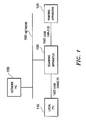
- Fig. 1 is a block diagram showing whole structure of an image system in embodiment 1.
- an image processing system comprises a scanning apparatus 100 (i.e. scanner), a local PC 110, a printing apparatus 120 (i.e. printer), a network PC 130, a USB cable (1) 140, a USB cable (2) 150 and a network 160.
- the scanning apparatus 100 is an image processing apparatus which reads image information from a manuscript image, changes the image information into image data and outputs the image data.
- the scanning apparatus 100 is connected with the network 160. Further, on the scanning apparatus 100, the local PC 110 is connected via the USB cable (1) 140, and the printing apparatus 120 is connected via the USB cable (2) 150.
- the local PC 110 is connected with the scanning apparatus 100 via the USB cable (1) 140 and is a host apparatus such as a personal computer (PC) executing reception and transmission of image data with the scanning apparatus 100.
- PC personal computer
- the printing apparatus 120 is connected with the scanning apparatus 100 via the USB cable (2) 150 and is an image forming apparatus to receive image data and the like and perform a print output.
- the network PC 130 is connected with the scanning apparatus 100 via the network 160 and is a host apparatus such as a personal computer (PC) executing reception and transmission of image data with scanning apparatus 100.
- PC personal computer
- the USB cable (1) 140 is a connecting means to communicatively connect the local PC 110 as a host to the scanning apparatus 100 as a device on the basis of USB protocol.
- the USB cable (1) 150 is a connecting means to communicatively connect the scanning apparatus 100 as a host to the printing apparatus 120 as a device on the basis of USB protocol.
- the network 160 is a communication network is laid in a relative narrow range such as LAN (Local Area Network) and the like.
- Fig. 2 is a block diagram showing internal structure of a scanning apparatus in embodiment 1.
- the scanning apparatus 100 includes a reading section 1, an image processing section 2, a USB controlling section 3, a printer management information acquiring section 4, a printer management information storing section 5, an operation panel 6, a compressing section 7, a copy controlling section 8, a PC scanner controlling section 9, a PC printer controlling section 10, an E-mail controlling section 11, a resource managing section 12, an image memory 13, a network controlling section 14, a CPU 15, a ROM 16, a RAM 17 and a common bus 18.
- the reading section 1 is a part to read manuscript image.
- the image processing section 2 is a part to change image information read by the reading section 1 into image data.
- the USB controlling section 3 has a device controlling portion 3-1 and accepts a control from the local PC 110 (Fig. 1) via the USB cable (1) 140 by the device controlling portion 3-1. Further, the USB controlling section 3 has a host controlling portion 3-2 and controls the printing apparatus 120 (Fig. 1) via the USB cable (2) 150 by the host controlling portion 3-2. That is, the device controlling portion 3-1 is a means to make the scanning apparatus 100 function as a device of the local PC 110; the host controlling portion 3-2 a means to make the scanning apparatus 100 function as a host of the printing apparatus 120. the
- the printer management information acquiring section 4 is a part to acquire printer management information from the printing apparatus 120 (Fig. 1) via the USB cable (2) 150. Here, the printer management information will be explained.
- Fig. 3 is an explanation diagram of printer management information.
- the printer management information contains option information, expendable information, paper information, print sheet number information, printer setting information, printer state (information), printing apparatus information and the like, they are formed from information displaying current quantity of expendable, work record or the like of the printing apparatus 120.
- the printer management information is acquired by the printer management information acquiring section 4 whenever the printing apparatus 120 ends print job in general.
- the printer management information storing section 5 is a memory to store the acquired printer management information.
- the printer management information is updated by the printer management information acquiring section 4 whenever print job is end.
- the operation panel 6 is a part to make user perform operation and setting of the scanning apparatus 100.
- the compressing section 7 is a part to compress image data processed by the image processing section 2.
- the copy controlling section 8 is a part to realize a copy function through combining the scanning apparatus 100 with the printing apparatus 120.
- the PC scanner controlling section 9 is a part to make the scanning apparatus 100 function as a PC scanner.
- the PC printer controlling section 10 is a part, once received the data packet from PC, to transfer data packet to the printing apparatus 120.
- the E-mail controlling section 11 is a part to control reception and transmission of E-mail to network PC 130.
- the resource managing section 12 is a part to manage and adjust work situation of the scanning apparatus 100 as that plural functions such as network scanner function, network printer function, copy function and the like do not simultaneously work in the scanning apparatus 100.
- the image memory 13 a memory to temporarily memorize image data used when the reading section 1, the image processing section 2 and the compressing section 7 perform respective processes. Serving as the memory, in general, it may be a part of memorizing area of the RAM 17.
- the network controlling section 14 has a data transferring portion 14-1, a data analyzing portion 14-2, a printer control language changing portion 14-3 and an information source setting portion 14-4 and is a part to make the scanning apparatus 100 (Fig. 1) connect to the network 160 (Fig. 1).
- the data transferring portion 14-1 is a means to execute reception and transmission of data packet between the network 160 (Fig. 1) and the scanning apparatus 100 (Fig. 1).
- the data analyzing portion 14-2 is a means to analyze data packet received by the data transferring portion 14-1.
- the printer control language changing portion 14-3 is a means to change the data packet received by the data transferring portion 14-1 into PJL (Printer Job control Language) which is a language capable of being understood by the printing apparatus 120 without network function, in the case that the data packet is a printer management protocol signal according to SNMP network protocol.
- PJL Printer Job control Language
- the information source setting portion 14-4 is a setting means which, in the case that an acquisition request of management information of the printing apparatus 120 is transmitted from the network PC 130 (Fig. 1), on the basis of information of the resource managing section 12, if the printing apparatus 120 (Fig. 1) is judged to be in non-work situation (un-printing situation), transfers an acquisition request of management information and returns management information based on a response with respect to the printing apparatus 120 (Fig. 1); and if the printing apparatus 120 (Fig. 1) is judged to be in work situation (printing situation), reads management information from the printer management information storing section 5 and returns the management information.
- the CPU 15 is a micro-processor to execute a control program previously stored in the ROM 16 so as to start or control the all compositions stated above.
- the ROM 16 is a read only memory to previously store a control program to be executed by the CPU 15 for starting or controlling the all compositions stated above.
- the RAM 17 is a random access memory to provide calculation area used in processing course of the CPU 15.
- the common bus 18 is a signal path to communicatively connect respective compositions.
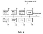
- Fig. 4 is a block diagram showing internal structure of a printing apparatus in embodiment 1.
- the printing apparatus 120 in embodiment 1 includes an emulation section 21, an image memory 22, a defrosting section 23, a USB controlling section 24, a printing section 25, a CPU 26, a ROM 27 and a RAM 28.
- the emulation section 21 is a part to handle printer description language (PDL) and PJL language.
- the image memory 22 is a memory to temporarily memorize image data in processing, and generally is a part of memory area through assigning the RAM 28.
- the defrosting section 23 is a part to defrost data packet compressed and transmitted so as to elongate the data packet.
- the USB controlling section 24 is a part to receive a control of the USB cable (2) 150.
- the printing section 25 is a print engine to print received image data.
- the CPU 26 is a micro-processor to execute a control program previously stored in the ROM 27 so as to start or control the all compositions stated above.
- the ROM 27 is a read only memory to previously store a control program to be executed by the CPU 26 for starting or controlling the all compositions stated above.
- the RAM 28 is a random access memory to provide calculation area used in processing course of the CPU 26.
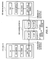
- Fig. 5 is a system structure diagram on the basis of a USB control.
- a communication following USB protocol is performed between the local PC 110 and the scanning apparatus 100, and between the scanning apparatus 100 and the printing apparatus 120.
- data is processed by GDI (Graphic Device Interface) process, JBIG (Joint Bi-level Image experts Group) compression process and PDL (Page Description Language) change process; and is sent to a USB Host portion.
- change data is constructed from data packet, and is transmitted to the device controlling portion 3-1 of the scanning apparatus 100 according to USB protocol.
- the host controlling portion 3-2 of the scanning apparatus 100 transmits data packet to a USB device portion of the printing apparatus 120 according to USB protocol.
- data packet is processed by analyzing process, PDL change process and JBIG elongation process, and is used in print output.
- Fig. 6 is an explanation a USB control.
- a device control means (a) is controlled by a host controlling means (b). Therefore, in the communication between the local PC 110 (Fig. 1) and the scanning apparatus 100 (Fig. 1), the host controlling means (b) is provided to the local PC 110 (Fig. 1) and the device controlling means (a) is provided to the scanning apparatus 100 (Fig. 1). In the communication between the scanning apparatus 100 (Fig. 1) and the printing apparatus 120 (Fig. 1), the host controlling means (b) is provided to the scanning apparatus 100 (Fig. 1) and the device controlling means (a) is provided to the printing apparatus 120 (Fig. 1).
- the device controlling means (a) has a RxBuff (buffer) for receiving data packet from the host controlling means (b) and a TxBuff (buffer) for transmitting data packet to the host controlling means (b).
- the host controlling means (b) has a RxBuff (buffer) for receiving data packet from the device controlling means (a) and a TxBuff (buffer) for transmitting data packet to the device controlling means (a).
- the scanning apparatus 100 When the scanning apparatus 100 (Fig. 1) is connected to the local PC 110 (Fig. 1) via the USB cable (1) 140 (Fig. 1), the scanning apparatus 100 (Fig. 1) is in an attaching state.
- the attaching state is a state in which the signal line D+ or D- of the USB cable (1) 140 (Fig. 1) is 3.3V (volt).
- the local PC 110 (Fig. 1) detects the attaching state of the scanning apparatus 100 (Fig. 1), then after 110 mSec passed, requests the scanning apparatus 100 (Fig. 1) to reset. The resetting request is to make the signal line D+ or D- become low level (0V).
- the scanning apparatus 100 when detected the resetting request, resets respective sections and becomes default state.
- a control transfer using pipe 0 becomes possible.
- a communication route is established according to an order of setup stage, data stage and status stage as follows.
- token packet and data packet for setup are transmitted from the local PC 110 (Fig. 1), then handshake packet is returned from the scanning apparatus 100 (Fig. 1).
- IN token packet is transmitted from the local PC 110 (Fig. 1) to the scanning apparatus 100 (Fig. 1)
- the scanning apparatus 100 if the scanning apparatus 100 (Fig. 1) can perform data transmission, the scanning apparatus 100 transmits data packet; but if the scanning apparatus 100 (Fig. 1) can not perform data transmission, the scanning apparatus 100 transmits handshake packet.
- the data packet is transmitted from the scanning apparatus 100 (Fig. 1)
- the local PC 110 1108 can correctly receive, ACK packet of the handshake packet is transmitted from the local PC 110 (Fig. 1) to the scanning apparatus 100 (Fig. 1).
- the device controlling portion 3-1 (Fig. 2) of the scanning apparatus 100 has an area (called: device descriptor) describing attributes of its own, through the local PC 110 (Fig. 1) reads out its content, the local PC 110 can identify the kind of the scanning apparatus 100 (Fig. 1), then executes an appropriate control.
- the scanning apparatus 100 uses the device descriptor to report its own attributes to the local PC 110 (Fig. 1), whenever the local PC 110 (Fig. 1) requests device descriptor information, the scanning apparatus 100 returns its own information. Then, address is assigned by the local PC 110 (Fig. 1), and when the device structure of the scanning apparatus 100 (Fig. 1) is identified, the local PC 110 (Fig. 1) and the scanning apparatus 100 (Fig. 1) are communicatively connected according to USB protocol.
- the host controlling means (b) is provided to the scanning apparatus 100 (Fig. 1) and the device controlling means (a) is provided to the printing apparatus 120 (Fig. 1)
- a configuration is established (between the scanning apparatus 100 and the printing apparatus 120), through the scanning apparatus 100 (Fig. 1), with respect to the printing apparatus 120 (Fig. 1), address is assigned, and when the device structure of the printing apparatus 120 (Fig. 1) is identified, the scanning apparatus 100 (Fig. 1) and the printing apparatus 120 (Fig. 1) are communicatively connected according to USB protocol.
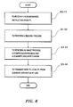
- Fig. 7 is a flowchart showing operations while PC print.
- the scanning apparatus 100 receives data packet of print data from the local PC 110 (Fig. 1) via the USB cable (1) 140 (Fig. 1).
- the data packet (print data) is temporarily stored in the RxBuff of the device controlling portion 3-1 (Fig. 5).
- the USB controlling section 3 (Fig. 2) performs a Cpu transfer or a hardware transfer to transfer the data packet of print data from the RxBuff of the device controlling portion 3-1 (Fig. 5) to the TxBuff of the host controlling portion 3-2 (Fig. 5).
- the USB controlling section 3 (Fig. 2) transmits the data packet of the print data to the printing apparatus 120 (Fig. 1) from the host controlling portion 3-2 (Fig. 5).
- the printing apparatus 120 (Fig. 1) analyzes the data packet of the print data, obtains the print data and performs a general print process.
- the scanning apparatus 100 (Fig. 2), after the print process ended, with respect to the printing apparatus 120 (Fig. 1), issues a management information acquisition command of printer language.
- a judgment of print process end is executed by the scanning apparatus 100 (Fig. 2).
- the printing apparatus 120 (Fig. 1) having received the management information acquisition command transmits printer management information to the scanning apparatus 100 (Fig. 2).
- the scanning apparatus 100 (Fig. 2) stores the acquired printer management information into the printer management information storing section 5 (Fig. 2), then ends the flow.
- Fig. 8 is a flowchart showing operations while PC scan.
- the local PC 110 (Fig. 1) transmits a start command of PC scan use in order to request an execution of PC scan.
- the device controlling portion 3-1 (Fig. 2) receives the start command (to receive a scan beginning instruction).
- the device controlling portion 3-1 (Fig. 2), after received the start command of PC scan use, performs a command analyzation, if judged that the command is the start command of PC scan use, transmits the start command to the PC scanner controlling section 9 (Fig. 2).
- the PC scanner controlling section 9 starts the reading section 1 (Fig. 2) to read a manuscript image.
- the image processing section 2 (Fig. 2) and the compressing section 7 (Fig. 2) perform an image process, a compression process and a scanner language change with respect to read data.
- the scanner language has a formation combining the read data into communication use command capable of being interpreted by host apparatus.
- the host controlling portion 3-2 constructs data packet from the read data performed the image process, the compression process and the scanner language change, and transmits the data packet to the local PC 110 (Fig. 1) from the device controlling portion 3-1 (Fig. 2) via the USB cable (1) 140 (Fig. 1), then ends the flow.
- Fig. 9 is a flowchart showing operations while copy.
- a copy process is started by user through the operation panel 6 (Fig. 2).
- the copy controlling section 8 starts the reading section 1 (Fig. 2) to read a manuscript image.
- An image process, a compression process and a printer language change are executed on the basis of designation of user through the operation panel 6 (Fig. 2).
- the copy controlling section 8 (Fig. 2) transmits print data performed the image process, the compression process and the printer language change to the host controlling portion 3-2 (Fig. 2).
- the host controlling portion 3-2 (Fig. 2) constructs data packet, and transmits the data packet to the printing apparatus 120 (Fig. 1).
- the printing apparatus 120 (Fig. 1) receives the data packet and obtains print data, then executes a copy (print process).
- the scanning apparatus 100 (Fig. 2), after the print process ended, with respect to the printing apparatus 120 (Fig. 1), issues a management information acquisition command of printer language.
- a judgment of print process end is executed by the scanning apparatus 100 (Fig. 2).
- the printing apparatus 120 (Fig. 1) having received the management information acquisition command transmits printer management information to the scanning apparatus 100 (Fig. 2).
- the scanning apparatus 100 (Fig. 2) stores the acquired printer management information into the printer management information storing section 5 (Fig. 2), then ends the flow.
- Fig. 10 is a system structure diagram on the basis of a network control.
- a communication following TCP/IP protocol is executed, and in between the scanning apparatus 100 and the printing apparatus 120, a communication following USB protocol is executed.
- print data is processed by a GDI process, a JBIG compression process and a PDL change process; then is sent to a network controlling section of the network PC 130; and is used to construct data packet on the basis of TCP/IP protocol; further is transmitted to the data transferring portion 14-1 of the scanning apparatus 100 via network. Later, the data packet is transmitted from the host controlling portion 3-2 of the scanning apparatus 100 to USB device controlling means of the printing apparatus 120 according to USB protocol. Further, in the inside of the printing apparatus 120, the data packet is analyzed, is PDL-expansion-processed and is JBIG-elongation-processed; then is printed and outputted.
- the data packet transfered by the printing apparatus 120 is temporarily stored in RxBuff of the host controlling portion 3-2 through the above-stated USB control.
- the data packet is sent to TxBuff through Cpu transfer or hardware transfer and is stored in the TxBuff; later, is transmitted to the data transferring portion 14-1; further, is transmitted to the network PC 130 (Fig. 1) via the network 160 (Fig. 1).
- Fig. 11 is a flowchart showing operations of network print process.
- the scanning apparatus 100 receives data packet of print data from the network PC 130 (Fig. 1) via the network 160 (Fig. 1).
- the data packet (print data) is temporarily stored in the RxBuff of the data transferring portion 14-1 (Fig. 10).
- the data packet (print data) stored in the RxBuff of the data transferring portion 14-1 (Fig. 10) is sent to TxBuff of the host controlling portion 3-2 (Fig. 10) through a Cpu transfer or a hardware transfer.
- the host controlling portion 3-2 (Fig. 10) transmits the data packet (print data) stored in the TxBuff to the printing apparatus 120 (Fig. 10).
- the printing apparatus 120 (Fig. 10) analyzes the data packet of the print data, obtains the print data and performs a print process.
- the scanning apparatus 100 (Fig. 10), after the print process ended, with respect to the printing apparatus 120 (Fig. 10), issues a management information acquisition command of printer language.
- a judgment of print process end is executed by the scanning apparatus 100 (Fig. 10).
- the printing apparatus 120 (Fig. 10) having received the management information acquisition command transmits printer management information to the scanning apparatus 100 (Fig. 10).
- the scanning apparatus 100 (Fig. 10) stores the acquired printer management information into the printer management information storing section 5 (Fig. 2), then ends the flow.
- Fig. 12 is a system structure diagram on the basis of a printer management information acquisition control.
- a communication following TCP/IP protocol is executed, and in between the scanning apparatus 100 and the printing apparatus 120, a communication following USB protocol is executed.
- a printer management information acquisition control tool for managing printing apparatus is installed by using SNMP (Simple Network Management Protocol) and MIB (management Information Base).
- SNMP Simple Network Management Protocol
- MIB management Information Base
- a printer management information acquisition command is transmitted from the network PC 130 to the scanning apparatus 100.
- the scanning apparatus 100 after received the command, changes the command into PJL (Printer Job control Language) capable be interpreted by the printing apparatus 120; and transmits the command to the printing apparatus 120 or send the command to the printer management information acquiring section 4 on the basis of control of the information source setting portion 14-4.
- PJL Print Job control Language
- the operation is performed on the basis of USB control.
- the data packet transfered by the printing apparatus 120 (Fig. 1) is temporarily stored in RxBuff of the host controlling portion 3-2 through the above-stated USB control.
- the data packet is further stored into TxBuff of the data transferring portion 14-1 through the printer management information acquisition control tool.
- the data transferring portion 14-1 transmits the data packet to the network PC 130 via the network 160 (Fig. 1).
- Alike, information acquired from the printer management information acquiring section 4 is also stored into the TxBuff of the data transferring portion 14-1 through the printer management information acquisition control tool.
- Fig. 13 is a first flowchart showing operations of printer management information acquisition control
- Fig. 14 is a second flowchart showing operations of printer management information acquisition control.
- Fig. 15 is a third flowchart showing operations of printer management information acquisition control.
- Data packet transmitted from the network PC 130 (Fig. 12) is stored into RxBuff of the data transferring portion 14-1 (Fig. 12) if the scanning apparatus 100 (Fig. 12).
- the data analyzing portion 14-2 judges whether the received data packet is printer management information acquisition command.
- Step S1-44 is executed; if the received data packet is print data, Step S1-52 is executed.
- the command is changed into PJL language capable of being interpreted by the printing apparatus 120 (Fig. 12), through the printer control language changing portion 14-3 (Fig. 12).
- the information source setting portion 14-4 confirms a work situation of the printing apparatus 120 (Fig. 12) with respect to the resource managing section 12 (Fig. 12).
- the resource managing section 12 manages a time in which print data is being transmitted to the printing apparatus 120 (Fig. 12) and a predetermined time after the print data comes to an end, and judges that the printing apparatus 120 (Fig. 12) is working while that times.
- Step S1-47 is executed; in the case that the printing apparatus 120 (Fig. 12) is working, Step S1-56 is executed.
- the data changed into interpretable language is sent to TxBuff of the host controlling portion 3-2 (Fig. 12) through a Cpu transfer or a hardware transfer.
- the host controlling portion 3-2 constructs data packet from the data stored in the TxBuff, and transmits the data packet to the printing apparatus 120 (Fig. 12)
- the host controlling portion 3-2 receives a response from the printing apparatus 120 (Fig. 12).
- the printer control language changing portion 14-3 (Fig. 12) changes the response (data) into MIB information.
- the data transferring portion 14-1 (Fig. 12) transmits the MIB information to the network PC 130 (Fig. 12) according to SNMP protocol, and ends the flow.
- the data packet received in RxBuff of the data transferring portion 14-1 (Fig. 12) is sent to Txbuff of the host controlling portion 3-2 (Fig. 12) through a Cpu transfer or a hardware transfer.
- the host controlling portion 3-2 (Fig. 12) transmits the data packet stored in the TxBuff to the printing apparatus 120 (Fig. 12) from the host controlling portion 3-2 (Fig. 12).
- the printing apparatus 120 obtains print data from the data packet and executes a general print process.
- the scanning apparatus 100 (Fig. 12), after the print process ended, with respect to the printing apparatus 120 (Fig. 12), issues a management information acquisition command of printer language.
- a judgment of print process end is executed by the scanning apparatus 100 (Fig. 12).
- the printing apparatus 120 (Fig. 12) having received the management information acquisition command transmits printer management information to the scanning apparatus 100 (Fig. 12).
- the scanning apparatus 100 (Fig. 12) stores the acquired printer management information into the printer management information storing section 5 (Fig. 2), then ends the flow.
- the information source setting portion 14-4 (Fig. 12) identifies that the printing apparatus 120 (Fig. 12) is working.
- the printer management information acquiring section 4 acquires printer management information from the printer management information storing section 5 (Fig. 12).
- the printer control language changing portion 14-3 (Fig. 12) changes the printer management information into network protocol language
- the data transferring portion 14-1 (Fig. 12) constructs data packet from the printer management information and transmits the data packet to the network PC 130 (Fig. 12). Then, the flow is ended.
- the image processing system comprises a printer management information storing section to store printer management information acquired by a printer management information acquiring section; and a network controlling section which, with respect to a printer management information acquisition request of printing apparatus received from a network PC, according to work situation of the printing apparatus, receives the printer management information from either of the printer management information storing section and the printing apparatus, and return the printer management information to the network PC. Therefore, even if the printing apparatus is working, it is possible to performs a response with respect to the printer management information acquisition request if the printing apparatus 120 received from the network PC.
- the printer management information which is acquired by the printer management information acquisition means after printing is ended is firstly stored into the printer management information storing section, then is read out from the printer management information storing section so as to reply with respect to the printer management information acquisition request received from the network PC while the printing apparatus is working.
- the judgment of print end is performed by the scanning apparatus, and when the receiving of print data is stopped for a predetermined time, the scanning apparatus judges print is ended. Therefore, in the case that there is a printer management information acquisition request just after printing, the printer management information stored in the printer management information storing section is different from newest data. Because of this, in the embodiment, a JOB end command is contained in USB data packet sent by host apparatus, then the scanning apparatus performs a print end judgment.
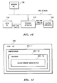
- Fig. 16 is a block diagram showing whole structure of an image system in embodiment 2.
- an image processing system comprises a local PC 200, a scanning apparatus 210 (i.e. scanner), a printing apparatus 120 (i.e. printer), a network PC 130, a USB cable (1) 140, a USB cable (2) 150 and a network 160.
- a scanning apparatus 210 i.e. scanner
- a printing apparatus 120 i.e. printer
- a network PC 130 a USB cable (1) 140
- a USB cable (2) 150 a network 160.
- Fig. 17 is an explanation diagram of a local PC addition structure in embodiment 2.
- a USB driver 200-1a is installed, in inside of the USB driver 200-1a, a JOB end command making section 200-1b is provided.
- the JOB end command making section 200-1b is a part to make a JOB end command for informing the scanning apparatus 210 (Fig. 17) of an end of print job.
- the command is made as a vendor command of control of USB protocol.
- a JOB end command serving as vendor definition command is appended. That is, the command is realized by previously performs a definition to a vendor request of control transfer of USB protocol.
- the JOB end command making section 200-1b when a print job of PC print in the embodiment 2 ended, generates the command (vendor request) and sends it, then an end of print job is informed.
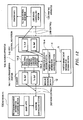
- Fig. 18 is a block diagram showing internal structure of a scanning apparatus in embodiment 2.
- the scanning apparatus 210 includes a reading section 1, an image processing section 2, a USB controlling section 3, a printer management information acquiring section 4, a printer management information storing section 5, an operation panel 6, a compressing section 7, a copy controlling section 8, a PC scanner controlling section 9, a PC printer controlling section 31, an E-mail controlling section 11, a resource managing section 12, an image memory 13, a network controlling section 14, a CPU 32, a ROM 33, a RAM 17 and a common bus 18.
- the PC printer controlling section 31 in the scanning apparatus 210 is a part, once received the data packet from PC, to transfer data packet to the printing apparatus 120; and has a command analyzing portion 31-1 and a PC print later processing portion 31-2.
- the command analyzing portion 31-1 is a means to abstract the JOB end command from various kinds of commands sent from the local PC 200 (Fig. 16). Then in order to make printer management information acquiring section 4 to acquire printer management information, the PC print later processing portion 31-2 is a means to communicate a series of command/response and the like, when the command analyzing portion 31-1 detected the JOB end command.
- the CPU 32 is a micro-processor to execute a control program previously stored in the ROM 33 so as to start or control the all compositions stated above.
- the command analyzing portion 31-1 and the PC print later processing portion 31-2 are added.
- the ROM 33 is a read only memory to previously store a control program to be executed by the CPU 32 for starting or controlling the all compositions stated above.
- a control program to start and control the command analyzing portion 31-1 and the PC print later processing portion 31-2 is added.
- the Fig. 19 showed processing contents in the case that the local PC 200 (Fig. 16) uses the printing apparatus 120 (Fig. 16) to execute a PC print on the basis of USB control, and as stated by Fig. 17, the JOB end command is sent at the end of print JOB.
- the command analyzing portion 31-1 (Fig. 18) analyzes a vendor command contained in data packet received on the basis of USB control.
- a detection to detect a JOB end command is waited, and when the detection is performed, a next step is executed.
- PC print later processing portion 31-2 uses PJL to ask whether a print process in the printing apparatus 120 ended via the host controlling portion 3-2 (Fig. 18).
- the printer management information acquiring section 4 uses the PJL to acquire the printer management information from the printing apparatus 120 (Fig. 18), and stores the printer management information into the printer management information storing section 5 (Fig. 18), then ends the flow.
- the resource managing section 12 manages a situation in a period from starting to send print data to the printing apparatus 120 (Fig. 16) to that the PC print later processing portion 31-2 (Fig. 18) received a response of print process end from the printing apparatus 120 (Fig. 18), as printer work situation
- the scanning apparatus executes a print end judgment. Therefore, it is possible to obtain a newest printer management information from the printer management information storing section in inside of the scanning apparatus. Because of this, an effect can be obtained to always provide newest printer management information with respect to the acquisition request of the printer management information from the network PC.
- the scanning apparatus executes a print end judgment.
- the scanning apparatus monitors a network connection, inquires the printing apparatus when the network connection is broken, then receives a response of print process end and performs a judgment.
- Fig. 20 is a block diagram showing whole structure of an image system in embodiment 3.
- an image processing system comprises a local PC 200, a scanning apparatus 300 (i.e. scanner), a printing apparatus 120 (i.e. printer), a network PC 130, a USB cable (1) 140, a USB cable (2) 150 and a network 160.
- a scanning apparatus 300 i.e. scanner
- a printing apparatus 120 i.e. printer
- a network PC 130 a USB cable (1) 140
- a USB cable (2) 150 a network 160.
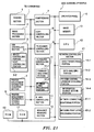
- Fig. 21 is a block diagram showing internal structure of a scanning apparatus in embodiment 3.
- the scanning apparatus 300 includes a reading section 1, an image processing section 2, a USB controlling section 3, a printer management information acquiring section 4, a printer management information storing section 5, an operation panel 6, a compressing section 7, a copy controlling section 8, a PC scanner controlling section 9, a PC printer controlling section 31, an E-mail controlling section 11, a resource managing section 12, an image memory 13, a network controlling section 41, a CPU 42, a ROM 43, a RAM 17 and a common bus 18.
- the network controlling section 41 has a data transferring portion 14-1, a data analyzing portion 14-2, a printer control language changing portion 14-3, an information source setting portion 14-4, a network connection monitoring portion 41-1 and a network print later processing portion 41-2; and it is a part to make the scanning apparatus 300 connect with the network 160.
- the data transferring portion 14-1 is a means to execute reception and transmission of data packet between the network 160 (Fig. 20) and the scanning apparatus 300 (Fig. 20).
- the data analyzing portion 14-2 is a means to analyze data packet received by the data transferring portion 14-1.
- the printer control language changing portion 14-3 is a means to change the data packet received by the data transferring portion 14-1 into language which is capable of being understood by the printing apparatus 120 without network function, in the case that the data packet is a control signal (except image data) according to network protocol.
- the network connection monitoring portion 41-1 is a means to monitor communication via the network 160 between the network PC 130 (Fig. 20) and the scanning apparatus 300 (Fig. 20), and to detect a break of network connection. Then, in order to make printer management information acquiring section 4 to acquire printer management information, the network print later processing portion 41-2 is a means to communicate a series of command/response and the like, when the network connection monitoring portion 41-1 detected the break of network connection.
- the CPU 42 is a micro-processor to execute a control program previously stored in the ROM 43 so as to start or control the all compositions stated above.
- the network connection monitoring portion 41-1 and the network print later processing portion 41-2 are added.
- the ROM 43 is a read only memory to previously store a control program to be executed by the CPU 42 for starting or controlling the all compositions stated above.
- a control program to start and control the network connection monitoring portion 41-1 and the network print later processing portion 41-2 is added.
- the Fig. 22 showed processing contents in the case that the network PC 130 (Fig. 20) uses the printing apparatus 120 (Fig. 20) to execute a PC print on the basis of USB control, and network connection is broken while a print is ending.
- the network connection monitoring portion 41-1 (Fig. 21) monitors a network connection.
- the monitoring operation is performed by monitoring a negotiation signal sent from the network PC 130 (Fig. 20).
- the network connection monitoring portion 41-1 (Fig. 21) stands by until the network connection is broken. When it is broken (the negotiation signal can not be received), next step is executed.
- a print function between the network PC 130 (Fig. 20) and the scanning apparatus 300 (Fig. 20) is realized by communication protocol called TCP/IP print.
- TCP/IP print when a series of print ended, a negotiation is performed by sending each other a packet signal of connection break request called FIN packet. Therefore, through detecting the FIN packet, it is possible to detect a break of the connection of the network printer.
- the network print later processing portion 41-2 uses PJL command to ask whether a print process in the printing apparatus 120 (Fig. 20) ended via the host controlling portion 3-2 (Fig. 21).
- the printer management information acquiring section 4 uses the PJL to acquire the printer management information from the printing apparatus 120 (Fig. 20), and stores/updates the printer management information into the printer management information storing section 5 (Fig. 21), then ends the flow.
- the resource managing section 12 manages a situation in a period from starting to send print data to the printing apparatus 120 to that the network print later processing portion 41-2 received a response of print process end from the printing apparatus 120 (Fig. 18), as work situation of the printing apparatus 120.
- the scanning apparatus executes a print end judgment. Therefore, it is possible to obtain a newest printer management information from the printer management information storing section in inside of the scanning apparatus. Because of this, an effect can be obtained to always provide newest printer management information with respect to the acquisition request of the printer management information from the network PC.
- the present invention is also capable of simply changing controlling program to detect a cancellation of USB configuration between the local PC and the scanning apparatus.
- the present invention can be applied to a fee-charging system of network printing apparatus.
- the printing apparatus if connected to the scanning apparatus, and the network PC printer management information of the printing apparatus. It can be considered to connect the printing apparatus to the network, and connect the scanning apparatus to the printing apparatus.
- the printing apparatus previously store management information of the scanning apparatus, once received a request to acquire the management information of the scanning apparatus from the network PC, according to the work situation of the scanning apparatus, sends to the network PC either of management information stored in its own side and management information acquired from the scanning apparatus.
- the management information of the scanning apparatus in the case may be various setting information, option installation information of ADF and the like, ID information of apparatus, life information of apparatus and the like.
Landscapes
- Engineering & Computer Science (AREA)
- Theoretical Computer Science (AREA)
- Human Computer Interaction (AREA)
- Physics & Mathematics (AREA)
- General Engineering & Computer Science (AREA)
- General Physics & Mathematics (AREA)
- Accessory Devices And Overall Control Thereof (AREA)
- Facsimiles In General (AREA)
- Computer And Data Communications (AREA)
Applications Claiming Priority (1)
| Application Number | Priority Date | Filing Date | Title |
|---|---|---|---|
| JP2005198897A JP4476886B2 (ja) | 2005-07-07 | 2005-07-07 | 画像処理装置及び画像処理システム |
Publications (3)
| Publication Number | Publication Date |
|---|---|
| EP1744243A2 true EP1744243A2 (de) | 2007-01-17 |
| EP1744243A3 EP1744243A3 (de) | 2011-05-04 |
| EP1744243B1 EP1744243B1 (de) | 2016-11-30 |
Family
ID=37150132
Family Applications (1)
| Application Number | Title | Priority Date | Filing Date |
|---|---|---|---|
| EP06116707.8A Ceased EP1744243B1 (de) | 2005-07-07 | 2006-07-06 | Bildverarbeitungsvorrichtung |
Country Status (4)
| Country | Link |
|---|---|
| US (1) | US8416431B2 (de) |
| EP (1) | EP1744243B1 (de) |
| JP (1) | JP4476886B2 (de) |
| CN (1) | CN1893511B (de) |
Families Citing this family (4)
| Publication number | Priority date | Publication date | Assignee | Title |
|---|---|---|---|---|
| JP4894680B2 (ja) * | 2007-08-22 | 2012-03-14 | セイコーエプソン株式会社 | 電子機器、外部機器、機器システム、状態情報送信方法 |
| US10165130B2 (en) * | 2014-02-13 | 2018-12-25 | Emerge Print Management, Llc | System and method for the passive monitoring and reporting of printer-related data on USB cables |
| WO2017177030A1 (en) * | 2016-04-06 | 2017-10-12 | Emerge Print Management, Llc | Apparatus and method for metering and monitoring printer related data on-networked printers |
| JP7647036B2 (ja) * | 2020-08-31 | 2025-03-18 | ブラザー工業株式会社 | 画像形成装置、画像形成システム及び記憶媒体 |
Citations (2)
| Publication number | Priority date | Publication date | Assignee | Title |
|---|---|---|---|---|
| JPH06183106A (ja) | 1992-12-15 | 1994-07-05 | Fuji Xerox Co Ltd | プリントシステム |
| US20020089692A1 (en) | 2001-01-11 | 2002-07-11 | Ferlitsch Andrew R. | Methods and systems for printing error recovery |
Family Cites Families (11)
| Publication number | Priority date | Publication date | Assignee | Title |
|---|---|---|---|---|
| US5887216A (en) * | 1997-03-19 | 1999-03-23 | Ricoh Company, Ltd. | Method and system to diagnos a business office device based on operating parameters set by a user |
| US5862404A (en) * | 1997-02-12 | 1999-01-19 | Toshiba America Information Systems, Inc. | Network device discovery and status information distribution using independent information distribution processes |
| DE60027637T2 (de) * | 1999-05-06 | 2006-09-28 | Seiko Epson Corp. | Netzwerkverwaltungssystem |
| US7120910B2 (en) * | 2000-03-29 | 2006-10-10 | Canon Kabushiki Kaisha | Control method for image processing apparatus connectable to computer network |
| JP3512015B2 (ja) * | 2001-03-30 | 2004-03-29 | ミノルタ株式会社 | ネットワークプリンティングシステム、プリンタ、サービス代行サーバ、及びプログラム |
| US7546365B2 (en) * | 2002-04-30 | 2009-06-09 | Canon Kabushiki Kaisha | Network device management system and method of controlling same |
| JP2004021669A (ja) * | 2002-06-18 | 2004-01-22 | Sanyo Electric Co Ltd | 転送制御システム、転送制御装置、記録装置および転送制御方法 |
| JP3747907B2 (ja) * | 2002-12-11 | 2006-02-22 | セイコーエプソン株式会社 | デバイス管理システム、プリンタ管理システム、プリンタ管理端末、ネットワークプリンタ、端末用プログラム及びプリンタ用プログラム、並びにデバイス管理方法 |
| JP2004220564A (ja) * | 2002-12-26 | 2004-08-05 | Seiko Epson Corp | デバイス連携管理システム、ネットワークデバイスおよびデバイス用プログラム、並びにデバイス連携管理方法 |
| CN1567284A (zh) * | 2003-06-13 | 2005-01-19 | 北京北佳信息系统有限公司 | 在网络环境下控制打印机使用的方法 |
| US8495202B2 (en) * | 2003-10-24 | 2013-07-23 | Brother Kogyo Kabushiki Kaisha | Imaging device information management system |
-
2005
- 2005-07-07 JP JP2005198897A patent/JP4476886B2/ja not_active Expired - Fee Related
-
2006
- 2006-07-03 CN CN2006101030071A patent/CN1893511B/zh not_active Expired - Fee Related
- 2006-07-06 EP EP06116707.8A patent/EP1744243B1/de not_active Ceased
- 2006-07-06 US US11/480,997 patent/US8416431B2/en not_active Expired - Fee Related
Patent Citations (2)
| Publication number | Priority date | Publication date | Assignee | Title |
|---|---|---|---|---|
| JPH06183106A (ja) | 1992-12-15 | 1994-07-05 | Fuji Xerox Co Ltd | プリントシステム |
| US20020089692A1 (en) | 2001-01-11 | 2002-07-11 | Ferlitsch Andrew R. | Methods and systems for printing error recovery |
Also Published As
| Publication number | Publication date |
|---|---|
| CN1893511B (zh) | 2012-08-08 |
| JP2007018242A (ja) | 2007-01-25 |
| US8416431B2 (en) | 2013-04-09 |
| JP4476886B2 (ja) | 2010-06-09 |
| EP1744243A3 (de) | 2011-05-04 |
| EP1744243B1 (de) | 2016-11-30 |
| US20070013947A1 (en) | 2007-01-18 |
| CN1893511A (zh) | 2007-01-10 |
Similar Documents
| Publication | Publication Date | Title |
|---|---|---|
| US9137395B2 (en) | Image processing device and computer-readable storage medium for use in connection with USB data packets | |
| US8570561B2 (en) | Image forming apparatus, printing control method, and computer-readable recording medium thereof | |
| US8542404B2 (en) | Image forming apparatus, image forming apparatus control method, and storage medium storing program | |
| US8830503B2 (en) | Image forming system including web server and screen update requests, web browser-equipped print control apparatus, and web browser-equipped image forming apparatus, and method of forming image in image forming system | |
| US9019524B2 (en) | Image forming apparatus, image forming system, method of controlling the same, and storage medium | |
| US8379259B2 (en) | Image forming system, device managing method thereof, and program therefor | |
| EP1744243A2 (de) | Bildverarbeitungsvorrichtung | |
| JP6582830B2 (ja) | モニタプログラム、通信プログラム、情報処理装置、画像形成装置、及び画像形成システム | |
| JP3703453B2 (ja) | 印刷制御装置およびデータ処理方法およびプログラムおよびコンピュータが読み取り可能な記憶媒体 | |
| US12585412B2 (en) | Information processing apparatus, and non-transitory computer-readable recording medium therefor to be compliant to a particular program | |
| JP2024023376A (ja) | プログラムセットおよび情報処理装置 | |
| CN100461815C (zh) | 图像输入装置和打印系统 | |
| JPH10136142A (ja) | 画像形成システム | |
| JP2007060126A (ja) | 画像形成装置及び画像形成方法 | |
| JP4536439B2 (ja) | 画像処理装置 | |
| JP4944227B2 (ja) | 画像処理装置 | |
| US11223741B2 (en) | Image reading apparatus | |
| JP3988597B2 (ja) | 画像出力システムおよびこれに用いられる画像出力装置、画像入力装置、制御方法 | |
| JP2008011427A (ja) | 画像データ伝送システム、複合デバイス、およびプログラム | |
| JP2002132483A (ja) | 画像出力システム | |
| JP2006270795A (ja) | 画像形成システムおよび方法および画像読取装置 | |
| JP2004086564A (ja) | 電子機器の制御方法、プログラム及び記録媒体 | |
| JP2008217399A (ja) | ネットワーク用アダプタ、機種及び機能情報の取得方法 | |
| JP2006260204A (ja) | リモート制御システム及び方法 | |
| JP2003219099A (ja) | 画像形成システム |
Legal Events
| Date | Code | Title | Description |
|---|---|---|---|
| PUAI | Public reference made under article 153(3) epc to a published international application that has entered the european phase |
Free format text: ORIGINAL CODE: 0009012 |
|
| AK | Designated contracting states |
Kind code of ref document: A2 Designated state(s): AT BE BG CH CY CZ DE DK EE ES FI FR GB GR HU IE IS IT LI LT LU LV MC NL PL PT RO SE SI SK TR |
|
| AX | Request for extension of the european patent |
Extension state: AL BA HR MK YU |
|
| PUAL | Search report despatched |
Free format text: ORIGINAL CODE: 0009013 |
|
| AK | Designated contracting states |
Kind code of ref document: A3 Designated state(s): AT BE BG CH CY CZ DE DK EE ES FI FR GB GR HU IE IS IT LI LT LU LV MC NL PL PT RO SE SI SK TR |
|
| AX | Request for extension of the european patent |
Extension state: AL BA HR MK RS |
|
| 17P | Request for examination filed |
Effective date: 20111026 |
|
| AKX | Designation fees paid |
Designated state(s): DE FR GB NL |
|
| GRAP | Despatch of communication of intention to grant a patent |
Free format text: ORIGINAL CODE: EPIDOSNIGR1 |
|
| INTG | Intention to grant announced |
Effective date: 20160721 |
|
| GRAS | Grant fee paid |
Free format text: ORIGINAL CODE: EPIDOSNIGR3 |
|
| GRAA | (expected) grant |
Free format text: ORIGINAL CODE: 0009210 |
|
| AK | Designated contracting states |
Kind code of ref document: B1 Designated state(s): DE FR GB NL |
|
| REG | Reference to a national code |
Ref country code: GB Ref legal event code: FG4D |
|
| REG | Reference to a national code |
Ref country code: DE Ref legal event code: R096 Ref document number: 602006051055 Country of ref document: DE |
|
| REG | Reference to a national code |
Ref country code: NL Ref legal event code: FP |
|
| REG | Reference to a national code |
Ref country code: FR Ref legal event code: PLFP Year of fee payment: 12 |
|
| REG | Reference to a national code |
Ref country code: DE Ref legal event code: R097 Ref document number: 602006051055 Country of ref document: DE |
|
| PLBE | No opposition filed within time limit |
Free format text: ORIGINAL CODE: 0009261 |
|
| STAA | Information on the status of an ep patent application or granted ep patent |
Free format text: STATUS: NO OPPOSITION FILED WITHIN TIME LIMIT |
|
| 26N | No opposition filed |
Effective date: 20170831 |
|
| REG | Reference to a national code |
Ref country code: FR Ref legal event code: PLFP Year of fee payment: 13 |
|
| PGFP | Annual fee paid to national office [announced via postgrant information from national office to epo] |
Ref country code: FR Payment date: 20200611 Year of fee payment: 15 |
|
| PGFP | Annual fee paid to national office [announced via postgrant information from national office to epo] |
Ref country code: GB Payment date: 20200624 Year of fee payment: 15 Ref country code: NL Payment date: 20200615 Year of fee payment: 15 |
|
| REG | Reference to a national code |
Ref country code: DE Ref legal event code: R082 Ref document number: 602006051055 Country of ref document: DE Representative=s name: VENNER SHIPLEY LLP, DE |
|
| PGFP | Annual fee paid to national office [announced via postgrant information from national office to epo] |
Ref country code: DE Payment date: 20200624 Year of fee payment: 15 |
|
| REG | Reference to a national code |
Ref country code: DE Ref legal event code: R119 Ref document number: 602006051055 Country of ref document: DE |
|
| REG | Reference to a national code |
Ref country code: NL Ref legal event code: MM Effective date: 20210801 |
|
| GBPC | Gb: european patent ceased through non-payment of renewal fee |
Effective date: 20210706 |
|
| PG25 | Lapsed in a contracting state [announced via postgrant information from national office to epo] |
Ref country code: GB Free format text: LAPSE BECAUSE OF NON-PAYMENT OF DUE FEES Effective date: 20210706 Ref country code: DE Free format text: LAPSE BECAUSE OF NON-PAYMENT OF DUE FEES Effective date: 20220201 |
|
| PG25 | Lapsed in a contracting state [announced via postgrant information from national office to epo] |
Ref country code: NL Free format text: LAPSE BECAUSE OF NON-PAYMENT OF DUE FEES Effective date: 20210801 Ref country code: FR Free format text: LAPSE BECAUSE OF NON-PAYMENT OF DUE FEES Effective date: 20210731 |