EP1742767B1 - Vliesstoff-schleifkörper und verfahren - Google Patents
Vliesstoff-schleifkörper und verfahren Download PDFInfo
- Publication number
- EP1742767B1 EP1742767B1 EP05725494A EP05725494A EP1742767B1 EP 1742767 B1 EP1742767 B1 EP 1742767B1 EP 05725494 A EP05725494 A EP 05725494A EP 05725494 A EP05725494 A EP 05725494A EP 1742767 B1 EP1742767 B1 EP 1742767B1
- Authority
- EP
- European Patent Office
- Prior art keywords
- substrate
- abrasive
- nonwoven
- abrasive article
- peaks
- Prior art date
- Legal status (The legal status is an assumption and is not a legal conclusion. Google has not performed a legal analysis and makes no representation as to the accuracy of the status listed.)
- Not-in-force
Links
Images

Classifications
-
- B—PERFORMING OPERATIONS; TRANSPORTING
- B24—GRINDING; POLISHING
- B24D—TOOLS FOR GRINDING, BUFFING OR SHARPENING
- B24D3/00—Physical features of abrasive bodies, or sheets, e.g. abrasive surfaces of special nature; Abrasive bodies or sheets characterised by their constituents
- B24D3/001—Physical features of abrasive bodies, or sheets, e.g. abrasive surfaces of special nature; Abrasive bodies or sheets characterised by their constituents the constituent being used as supporting member
- B24D3/002—Flexible supporting members, e.g. paper, woven, plastic materials
-
- B—PERFORMING OPERATIONS; TRANSPORTING
- B24—GRINDING; POLISHING
- B24D—TOOLS FOR GRINDING, BUFFING OR SHARPENING
- B24D11/00—Constructional features of flexible abrasive materials; Special features in the manufacture of such materials
- B24D11/001—Manufacture of flexible abrasive materials
-
- B—PERFORMING OPERATIONS; TRANSPORTING
- B24—GRINDING; POLISHING
- B24D—TOOLS FOR GRINDING, BUFFING OR SHARPENING
- B24D11/00—Constructional features of flexible abrasive materials; Special features in the manufacture of such materials
- B24D11/02—Backings, e.g. foils, webs, mesh fabrics
-
- B—PERFORMING OPERATIONS; TRANSPORTING
- B24—GRINDING; POLISHING
- B24D—TOOLS FOR GRINDING, BUFFING OR SHARPENING
- B24D13/00—Wheels having flexibly-acting working parts, e.g. buffing wheels; Mountings therefor
- B24D13/14—Wheels having flexibly-acting working parts, e.g. buffing wheels; Mountings therefor acting by the front face
-
- B—PERFORMING OPERATIONS; TRANSPORTING
- B24—GRINDING; POLISHING
- B24D—TOOLS FOR GRINDING, BUFFING OR SHARPENING
- B24D18/00—Manufacture of grinding tools or other grinding devices, e.g. wheels, not otherwise provided for
-
- B—PERFORMING OPERATIONS; TRANSPORTING
- B24—GRINDING; POLISHING
- B24D—TOOLS FOR GRINDING, BUFFING OR SHARPENING
- B24D3/00—Physical features of abrasive bodies, or sheets, e.g. abrasive surfaces of special nature; Abrasive bodies or sheets characterised by their constituents
- B24D3/02—Physical features of abrasive bodies, or sheets, e.g. abrasive surfaces of special nature; Abrasive bodies or sheets characterised by their constituents the constituent being used as bonding agent
- B24D3/20—Physical features of abrasive bodies, or sheets, e.g. abrasive surfaces of special nature; Abrasive bodies or sheets characterised by their constituents the constituent being used as bonding agent and being essentially organic
- B24D3/28—Resins or natural or synthetic macromolecular compounds
Definitions
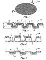
- This invention is directed to textured abrasive articles, which comprise a lofty nonwoven substrate with an abrasive coating thereon.
- Nonwoven abrasive products are generally made by applying an abrasive coating to a nonwoven substrate and curing the abrasive coating.
- Suitable nonwoven substrates may be provided by processes such as carded, air laid, spunbond, or wet laid processes. Nonwoven substrates may be needletacked to densify and mechanically-entangle constituent fibers. Initial "prebond" coatings may be applied and cured to stabilize the nonwoven substrate prior to further processing.
- Abrasive coatings or layers, which include a curable (hardenable) binder and abrasive particles, are applied to the nonwoven substrate to form the abrasive product.
- the document US-A-6 371 842 discloses an abrasive article including a substrate which, in one embodiment, comprises a thermoplastic material and a fibrous reinforcing material is the form of a nonwoven fibre mat.
- the substrate has a first surface and an opposite second surface, the first surface defining a plurality of peaks and valleys, the first surface and the second surface defining a thickness; and an abrasive coating comprising a binder and abrasive particles present on at least a portion of the first surface.
- Low density abrasive products of the type defined in U.S. Pat. No. 2,958,593 and sold under the registered trademark "SCOTCH-BRITE" by 3M Company of St. Paul, Minnesota, have found significant commercial success as surface treatment products.
- This type of abrasive product is typically formed of crimped staple fibers which have been formed into a mat and impregnated with resinous binder and abrasive. This material is made available commercially in a wide variety of types to provide many functions.
- nonwoven abrasive products are a disc or wheel for mounting on a rotating axis, a belt, a pad for finishing equipment, such as floor treating pads or a sheet for use as a hand pad.
- the abrasive article may be attached to a support during use, such as a back-up pad for a grinder, or, the abrasive article may include sufficient volume to use as a hand pad.
- nonwoven abrasive discs are preferred over coated abrasive discs, which generally have a cloth, paper or plastic backing, because the nonwoven discs are more conformable to the surface being finished.
- a nonwoven abrasive disc easily conforms around sharp corners and welds without tearing the disc or gouging the surface being finished.
- This conformability has its disadvantages for some applications, as the nonwoven discs usually have lower grinding characteristics (e.g., cut rate) than coated abrasive discs.
- nonwoven abrasive articles that retain the conformable aspects of nonwoven abrasive articles but have increased cut performance.
- the present invention is directed to nonwoven abrasive articles, particularly lofty nonwoven abrasive articles, which have a textured, non-planar surface.
- the textured surface composed of peaks or high regions and valleys or recessed regions, provides improved cut performance over nonwoven abrasive articles having a generally planar abrading surface.
- One common term for textured, non-planar is corrugated.
- the invention is directed to a nonwoven abrasive article comprising a lofty nonwoven substrate having a first surface and an opposite second surface, and an abrasive coating comprising a binder and abrasive particles present on at least a portion of the first surface.
- the first surface and the second surface define a plurality of peaks and valleys.
- the nonwoven has a thickness, defined by the first surface and the second surface, the thickness being substantially constant throughout the substrate.
- the present invention relates, in general, to an abrasive article having a lofty nonwoven material as the carrier substrate for an abrasive coating.
- the topography of the abrasive article is three-dimensional, and has an abrading surface that includes a number of peaks or raised regions separated by valleys or recessed regions.
- the abrasive coating may be present across the entire surface of the lofty nonwoven substrate or limited to the peaks or to the valleys.
- the abrasive coating may be present on either or both sides of the abrasive article.
- FIGS. 2-7 show various embodiments of abrasive article 10.
- Each abrasive article has a unique reference numeral (i.e., abrasive article 10A in FIG. 2 , abrasive article 10B in FIG. 3 , etc.), however, like features in the various embodiments are designated with the same reference numeral.
- abrasive article 10A has a substrate 12 supporting an abrasive coating 14.
- Substrate 12 is defined between a first surface 22 and an opposite, second surface 24.
- Substrate 12 has a plurality of peaks or raised regions 26 and a plurality of valleys or recessed regions 28.
- Each surface 22, 24 includes sidewall portions 27 which extend from peaks 26 to valleys 28.
- Second surface 24 follows the contours of first surface 22, thus creating a substrate with an essentially constant thickness.
- the thickness "t" of substrate 12 varies no more than 50% across substrate 12, typically no more than 30%. A thickness variation of no more than 20% is preferred.
- first surface 22 being the inverse of second surface 24
- second surface 24 allows for applying abrasive coating 14 on either or both of surfaces 22, 24 and still obtaining a textured abrasive surface.
- having a substrate 12, with an essentially constant thickness provides an abrasive article with a consistent surface for supporting an abrasive coating and provides an abrasive article with a consistent thickness, which provides consistent grinding or polishing results.
- Abrasive coating 14 has a plurality of abrasive particles 32 retained on first surface 22 of substrate 12 by a binder 34.
- Abrasive particles 32 may be distributed throughout binder 34 or may be generally present as a layer retained by binder 34.
- Abrasive article 10A has abrasive coating 14 present on peaks 26 and in valleys 28, and on sidewall portions 27 connecting peaks 26 with valleys 28. Variations of abrasive coating 14 are illustrated in FIGS. 3-5 .
- Abrasive article 10B, of FIG. 3 is similar to abrasive article 10A of FIG. 2 except that abrasive article 10B has abrasive coating 14 present on peaks 26 but not in valleys 28 or on sidewalls 27.
- Abrasive article 10C, of FIG. 4 is similar to abrasive article 10A of FIG. 2 except that abrasive article 10C has abrasive coating 14 in valleys 28 but not on peaks 26.
- the substrate of abrasive article 10D includes peaks 26, valleys 28, and land portions 30 connecting peaks 26 and valleys 28. Land portions 30 are an intermediate elevation between peaks 26 and valleys 28.
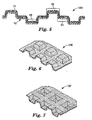
- FIGS. 6 and 7 illustrate two different embodiments of abrasive articles having a substrate with the same configuration, but the abrasive coating being on opposite sides of the substrate.
- the substrate has a plurality of valleys and peaks, with the abrasive coating present across the entire substrate.
- Abrasive article 10E, in FIG. 6 has individual peaks and interconnected valleys, with the abrasive coating present in both the peaks and valleys; the peaks resemble "pillows".
- abrasive article 10E In an alternate embodiment of abrasive article 10E, the abrasive coating could be present predominantly on the peaks or "pillows" of the lofty nonwoven substrate.
- Abrasive article 10F in FIG. 7 , has individual valleys and interconnected peaks; the valleys resemble "pockets".
- the abrasive coating could be present predominantly in the "pockets" of the lofty nonwoven substrate.
- the abrasive articles have a topography composed of peaks 26 and valleys 28 present as a rectilinear grid. That is, peaks 26 and valleys 28 are present across the width and the length of the abrasive article. Unlike those embodiments, abrasive article 10G of FIG. 8 has extended lengths of peaks 26 and valleys 28.
- Abrasive article 10 et seq. has an overall thickness, measured from the outer edge of abrasive article 10 to the outer most, opposite surface of article 10.
- thickness "T" is illustrated as being defined as the distance from the outer surface of abrasive coating 14 to the outer surface defined by second surface 24 of substrate 12.
- the thickness is defined as the distance from outer surface defined by the second substrate to the opposite surface, either the outer surface of abrasive coating 14 ( FIG. 3 ) or the top of peak 26 ( FIG. 4 ).
- the thickness of abrasive article 10 et seq. is at least 3 mm, usually at least 3.175 mm (1/8 inch), and often at least 6.35 mm (1/4 inch).
- Substrate 12 of abrasive article 10 et seq. is a lofty nonwoven fibrous material.
- lofty nonwoven what is intended is a layer of lofty nonwoven web material composed of a plurality of randomly oriented fibers, the layer having a thickness (prior to corragation) of at least 150 micrometers, usually at least 500 micrometers (0.5 mm).
- lofty nonwoven substrate 12 is at least 3.175 mm (1/8 inch) thick. Common thicknesses for substrate 12 are, for example, 6.35 mm (1/4 inch) and 12.7 mm (1/2 inch). Addition of a prebond binder onto the fibrous mat does not significantly alter the thickness of the substrate.
- the lofty nonwoven may decrease in thickness due to the pressure applied to the nonwoven during the corrugation process.
- the corrugated substrate 12 will retain least 35%, and preferably at least 50% of its original thickness compared to the nonwoven substrate prior to corrugating. It is not unexpected that a thicker nonwoven material will decrease more in thickness than a thinner nonwoven.
- the thickness of substrate 12, "t" from surface 22 to surface 24, after corrugation is at least 150 micrometers, usually at least 500 micrometers. In most embodiments, the thickness is at least 1000 micrometers (1 mm), and a preferred range is 1 mm to 15 mm. Typically, the thickness is no greater than 2 cm, often no greater than 1.5 cm. Common thicknesses for corrugated substrate 12 include 3.4 mm and 6.5 mm.
- Preferred components for the lofty nonwoven substrate 12 include nonwoven webs made from one or more of a variety of thermoplastic polymers that are known to form fibers.
- Suitable thermoplastic polymers can be selected from polyolefins (such as polyethylenes, polypropylenes, and polybutylenes), polyamides (such as nylon 6, nylon 6/6, and nylon 10), polyesters (such as polyethylene terephthalate), copolymers containing acrylic monomers, and blends and copolymers thereof.
- Semi-synthetic fibers such as acetate fibers
- natural fibers such as cotton
- regenerated fibers such as rayon
- other non-thermoplastic fibers can also be blended with the thermoplastic fibers.
- the fibers typically have a denier of from about 6 to about 200, more usually about 50 to about 100.
- the basis weight of the lofty nonwoven substrate 12 (fibers only, with no prebond binder layer) is preferably from about 50 grams per square meter to about 1 kilogram per square meter, and more preferably from about 150 to about 600 grams per square meter.
- a prebond binder is applied to the lofty nonwoven substrate to lock the fibers.
- the basis weight of the lofty nonwoven substrate 12, with prebond binder is usually from about 100 grams per square meter to about 2 kilogram per square meter, and more preferably from about 300 grams to about 1.5 kilogram per square meter.
- One particular suitable substrate 12, with prebond binder has a basis weight of about 1.15 kg/m 2 .
- the lofty nonwoven substrate can be prepared by any suitable web forming operation.
- the lofty nonwoven webs may be carded, spunbonded, spunlaced, melt blown, air laid, creped, or made by other processes as are known in the art.
- Substrate 12 has a three-dimensional topography present therein, thus providing a non-planar abrading surface for abrasive articles 10 et seq.
- Peaks 26 and valleys 28, which form the topography are preferably provided in a regular pattern or array on substrate 12.
- peaks or raised regions 26 can be provided as generally parallel continuous rows separated by valleys 28, as illustrated in FIG. 8 .
- peaks or raised regions 26 can be separated by valleys 28 in a pattern, typically a rectilinear grid.
- Raised regions 26 and valleys 28 can be rectangular or square, or have other patterns and shapes including but not limited to diamonds, circles, ovals, triangles, tear drops, hexagons, and octagons.
- Peaks 26 and valleys 28 could be provided in what appears to be a random pattern, but because the peaks are normally formed by rollers or other devices that would periodically repeat the random pattern, this arrangement may actually be a repeating random pattern, or semi-random pattern.
- the height of peaks 26 and depth of valleys 28 is defined by the distance of displacement of the substrate surface, either 22 or 24, from its non-corrugated state.
- the height of the peaks or depth of the valleys is also equal to the length of sidewall 27.
- the height of peaks 26, or depth of valleys 28 is generally uniform and ranges from about 0.5 mm to about 5 mm, preferably from about 1.5 mm to about 4 mm.
- the height of peaks 26 for one particular embodiment is 2.2 mm to 3.5 mm.
- the surface area of the individual peaks or raised regions ranges from about 9 mm to about 250 mm 2 .
- the surface area of peaks or raised regions 26 ranges from about 150 mm 2 to about 450 mm 2 (when measured for a section having a surface area of about 650 mm 2 ).
- the peaks can occupy from about 25% of the area to about 75% of the area.
- the ratio of area occupied by peaks 26 and valleys 28 is usually within the range of 25:75 to 75:25, and in most embodiments is within the range of 40:60 to 60:40.
- substrate 12 has a substantially constant thickness, with second surface 24 following first surface 22.
- a substrate having a 50:50 ratio of peak area 26 to valleys 28 is beneficial in that either surface 22, 24 can be coated and provide the same surface area of peaks 26 and valleys 28.
- the abrasive article may include a second substrate in addition to lofty nonwoven substrate 12.
- This second substrate may be a backing layer, present on the back side of the lofty nonwoven substrate, or may be a scrim or other layer present within the lofty nonwoven substrate.
- the second substrate may be included, for example, to stiffen the abrasive article, reduce stretching, provide improved tear resistance, provide an attachment mechanism, or to increase desired article properties (such as absorption).
- FIGS. 2-4 illustrate a backing 40 present on second surface 24, and FIG. 2 illustrates a scrim 42, such as a reinforcing scrim, present within substrate 12 between first surface 22 and second surface 24.
- second substrate 40, 42 is a permanent feature of abrasive article 10; that is, second substrate 40, 42 is not readily removable from substrate 12.
- Second substrate 40, 42 can be a fairly thin material, having a thickness less than the thickness of substrate 12.
- thin materials include a knitted or woven fabric or cloth, a nonwoven web, a thermoplastic or other plastic film, paper, or laminates thereof. Usual thickness for such materials is 250 micrometers to 4 mm, although thicker and thinner materials would also be suitable.
- Other suitable materials include substrates having loops or hooks thereon, which are one half of an attachment system and are used to attach abrasive article 10 to a back-up pad or the like.
- Second substrate 40 can alternately be fairly thick, having a thickness greater than the thickness of substrate 12.
- suitable thick second substrates 40 include sponges, which can be open cell or closed cell. Common sponge materials include cellulose and polyurethane. Usual thickness for such materials is 3.175 mm (1/8 inch) to 5.1 cm (2 inches) or more.
- second substrate 40 is attached to second surface 24 at valleys 28 and not at peaks 26, on the side of substrate 12 opposite abrasive coating 14. In such a construction, second substrate 40 is attached to substrate 12 after the texture has been imparted to substrate 12.
- Abrasive article 10C has second substrate 40 attached to second surface 24 at peaks 26 and valleys 28, on the side of substrate 12 opposite abrasive coating 14.
- second substrate 40 is attached to substrate 12 prior to or simultaneously to the texture being imparted to substrate 12.
- the texture is imparted to both substrate 12 and second substrate 40.
- FIG. 2 an embodiment of a scrim 42 is illustrated.
- Abrasive article 10A has second substrate 42 present within substrate 12, between first surface 22 and second surface 24. Scrim 42 may be positioned closer to one surface 22, 24 than the other, or, may be equally positioned therebetween. In such a construction, scrim 42 is positioned within substrate 12 prior to the texture being imparted to substrate 12. Scrim 42 may be positioned within substrate 12 during the manufacture of the lofty nonwoven material, or may be subsequently added, for example, by needle tacking. For embodiments where scrim 42 is needle tacked into substrate 12, scrim 42 is generally a woven or knitted mesh material.
- an adhesive may be used to secure second substrate 40 to second surface 24, or, if one or both of substrate 12 and second substrate 40 comprises thermoplastic material, the material can be heated and melted to secure substrates 12, 40 together.
- FIG. 9 schematically illustrates a method and equipment for forming a lofty nonwoven substrate 12 suitable for use in the abrasive articles of FIGS. 2-8 .
- the method illustrated in FIG. 9 generally includes forming a corrugated or textured substrate so that it has peaks or raised regions 26 and valleys or recessed regions 28.
- a second substrate is attached to one side of the textured substrate after the texture has been imparted.
- a web of preformed, uncorrugated lofty nonwoven material 200 is used as the starting material in the illustrated process.
- This lofty nonwoven material 200 is fed between first and second corrugating members or rollers 126 and 127 each having an axis and including a plurality of circumferentially spaced generally axially extending ridges 128 around and defining its periphery, with spaces between ridges 128 adapted to receive portions of ridges 128 of the other corrugating member, 126 or 127, in meshing relationship with nonwoven web 200 between meshed ridges 128.
- corrugating members 126,127 may be heated to facilitate the corrugation process; preferably, the heat is not so high that nonwoven material 200 appreciably melts, although some melting of fibers is acceptable.
- Corrugating members 126,127 are mounted in axially parallel relationship with portions of ridges 128 meshing, generally in the manner of gear teeth. At least one of corrugating members 126, 127 is rotated, and nonwoven material 200 is fed between the meshed portions of ridges 128 of corrugating members 126,127 to generally corrugate the nonwoven material 200. The corrugated nonwoven 200 is retained along the periphery of second corrugating member 127 after it has moved past the meshed portions of ridges 128.
- a backing member such as second substrate 40 of abrasive article 10B in FIG. 3 is applied to substrate 12.
- An adhesive layer 250 is extruded from a die 124 into a nip formed between second corrugating member 127 and a flat surfaced cooling roller 125 while simultaneously supplying a backing member 300 into the nip between corrugating member 127 and cooling roller 125 along the surface of roller 125. This results in adhesive layer 250 being deposited between backing member 300 and nonwoven material 200, thus bonding backing member 300 and nonwoven material 200 along valley portions 110. The resulting nonwoven laminate 100 is then carried partially around the cooling roller 125 to complete cooling.
- the substrates for abrasive article 10B could be formed by thermally or ultrasonically bonding backing member 300 to the corrugated nonwoven material.
- the method and equipment used for forming abrasive article 10C of FIG. 4 , having backing 40 laminated along the length of substrate 12 and following the peaks and valleys of substrate 12, is similar to and uses the same equipment illustrated in FIG. 9 , except that instead of extruding an adhesive layer to bond backing member 300 onto nonwoven web 200, backing member 300 is formed and bonded to nonwoven web 200 prior to web 200 progressing between corrugating members 126, 127.
- Abrasive coating 14, supported by substrate 12, is composed of abrasive particles 32 retained onto substrate 12 by binder 34.
- Abrasive particles 32 may be organic or inorganic particles.
- suitable inorganic abrasive particles include alumina or aluminum oxide, (such as fused aluminum oxide, heat treated fused aluminum oxide, ceramic aluminum oxide, heat treated aluminum oxide), silicon carbide, titanium diboride, alumina zirconia, diamond, boron carbide, ceria, aluminum silicates, cubic boron nitride, garnet, silica, and combinations thereof.
- Preferred fused aluminum oxides include those available commercially pretreated by Exolon ESK Company, Tonawanda, NY, or Washington Mills Electro Minerals Corp.
- Preferred ceramic aluminum oxide abrasive particles include those described in U.S. Pat. Nos.
- particles useful for this invention include solid glass spheres, hollow glass spheres, calcium carbonate, polymeric bubbles, silica and silicates, aluminum trihydrate, mullite, and pumice.
- Organic abrasive particles suitable for use in abrasive article are preferably formed from a thermoplastic polymer and/or a thermosetting polymer.
- Organic abrasive particles can be formed from a thermoplastic material such as polycarbonate, polyetherimide, polyester, polyvinyl chloride (PVC), polymethacrylate, polymethylmethacrylate, polyethylene, polysulfone, polystyrene, acrylonitrile-butadiene-styrene block copolymer, polypropylene, acetal polymers, polyurethanes, polyamide, and combinations thereof.
- the organic abrasive particle may be a mixture of a thermoplastic polymer and a thermosetting polymer.
- a preferred organic abrasive particle is a metal and mold cleaning plastic blast media available commercially as "MC” blast media from Maxi Blast Inc., South Bend, Ind., available with an antistatic coating, but preferably untreated.
- the "MC” media is a 99% melamine formaldehyde condensate, an amino thermoset plastic.
- the abrasive particles can have any precise shape or can be irregularly or randomly shaped. Examples of such three dimensional shapes includes: pyramids, cylinders, cones, spheres, blocks, cubes, polygons, and the like.
- the organic abrasive particles can be relatively flat and have a cross sectional shape such as a diamond, cross, circle, triangle, rectangle, square, oval, octagon, pentagon, hexagon, polygon and the like. Shaped abrasive particles, and methods of making them, are taught in U.S. Pat. Nos.
- Shaped thermosetting organic abrasive particles can be made in accordance with U.S. Pat. No. 5,500,273 , which is incorporated herein by reference.
- the surface of the abrasive particles may be treated with coupling agents to enhance adhesion to and/or dispersibility in binder 34.
- the average particle size of the abrasive particles for advantageous applications of the present invention is at least about 10 micrometers, usually at least about 50 micrometers, and preferably at least about 100 micrometers.
- a particle size of about 50 micrometers corresponds approximately to a coated abrasive grade 280 abrasive grain, according to American National Standards Institute (ANSI) Standard B74.18-1984, 100 micrometers to about grade 120, and 600 micrometers to about grade 30, all of which are suitable for abrasive articles according to the invention.
- Abrasive particles 32 can be oriented within abrasive coating 14, or can be applied to substrate 12 without orientation, depending upon the desired end use of abrasive article 10.
- Abrasive coating 14 can be applied to substrate 12 by conventional abrasive coating techniques.
- Abrasive coating 14 may have abrasive particles 32 dispersed throughout binder 34. Such a coating is obtained by applying a slurry of abrasive particles 32 and liquid binder 34 to substrate 12 and then curing or otherwise hardening binder 34. A second binder layer which may or may not have additional abrasive particle included, often referred to as a size coat, may be applied over the slurry layer and hardened.
- Another common abrasive coating 14 utilizes a make coat or a roll coat.
- a make coat or a roll coat Such a coating is obtained by applying a layer of liquid binder 34, usually by spraying or roll coating, to the substrate and then applying abrasive particles 32 thereon.
- Abrasive particles 32 may be merely dropped onto binder 34 or may be oriented, for example by an electrostatic field. Abrasive particles 32 are at least partially embedded into binder 34. After application of particles 32, binder 34 is cured or otherwise hardened.
- a second binder layer often referred to as size coat, may be applied over the make or roll coat and hardened.
- Binder 34 of abrasive coating 14 retains abrasive particles 32 onto substrate 12.
- Binder 34 is derived from a liquid binder or binder precursor, which comprises an organic polymerizable resin, which is hardened or cured to form binder 34.
- the binder precursor is exposed to an energy source which aids in the initiation of the polymerization or curing process. Examples of energy sources include thermal energy and radiation energy.
- energy sources include thermal energy and radiation energy.
- Binder 34 when solidified, hardened or cured, is non-tacky.
- organic resins suitable for binder 34 include phenolic resins (both resole and novolac), urea-formaldehyde resins, melamine formaldehyde resins, acrylated urethanes, acrylated epoxies, ethylenically unsaturated compounds, aminoplast derivatives having pendant unsaturated carbonyl groups, isocyanurate derivatives having at least one pendant acrylate group, isocyanate derivatives having at least one pendant acrylate group, vinyl ethers, epoxy resins, mixtures and combinations thereof. Other materials not within these groups are also suitable as binder 34.
- Abrasive articles 10 of the invention may be used in any application that uses conventional nonwoven abrasive articles.
- Abrasive articles of this invention may be available as grinding discs, as endless belts, as sheets, as hand pads, and the like.
- the inventive abrasive articles would be used in the same manner as conventional articles.
- a lofty nonwoven material having a weight of 293 g/m 2 , was prepared from 58 denier (64.5 dtex) x 5.1 cm nylon staple fibers using an air lay Rando Weber machine (commercially available from the Rando Machine Company, Ard, NY). The thickness of this lofty nonwoven material was about 1.8 cm.
- the resulting nonwoven was placed on a 301 g/m 2 woven polyester scrim cloth ("101x43 Polyester Cloth Power Strate", obtained from Milliken & Co., Spartanburg, SC) and the two layers were passed through a needle-tacking machine (commercially available from Dilo, Inc.
- the needle-tacking machine was operated at 600 strokes per minute, with a penetration depth of 13 mm, and at a rate of 6.1 m/min.
- the resultant nonwoven composite structure had about 55% of its thickness above the plane (top) defined by the polyester scrim cloth and about 45% below that plane (bottom).
- This composite was next passed through a pair of opposing rollers (having an outer diameter of 25.4 cm, or 10 inches) set at a pressure of about 1.75 kg/cm 2 .
- the top roller was heated to and held at 174 °C.
- the needled composite was then impregnated with a prebond resin precursor by passing it through a two-roll coater to provide a dry add-on weight of about 556 g/m 2 .
- the formulation of the prebond resin precursor is provided below.
- the prebond resin precursor After being coated onto the nonwoven material, the prebond resin precursor was cured in a tunnel oven at 143 °C for a period of about 4 minutes.
- the cured nonwoven prebond web was slit into 12 inch wide rolls for further processing for use in the examples listed below.
- the lofty nonwoven web was corrugated by a process and equipment similar to that illustrated in FIG. 9 except that the first and second intermeshing patterned rollers (corrugating members 126 and 127, respectively) were machined with a diamond pattern.
- the diamonds were approximately 8 mm per side and there were approximately 9 diamonds per square inch (6.45 cm 2 ) with a space between each diamond. Both pattern rolls were heated to 232 °C.
- the lofty nonwoven web was fed into the nip between the intermeshing patterned rollers such that the web first major surface was up.
- the resulting patterned nonwoven web had depressed regions or pockets on the first major surface of the web. Each pocket was about 3 mm deep.
- the surface of the web was spray coated at a line speed of 5 feet/min. (1.5m/min) with a resin/abrasive slurry using a spray gun ("BINKS SPRAY GUN #601") equipped with nozzle #59ASS and cap # 151(all obtained from Midway Industrial Supply Co., St. Paul, MN).
- the spray was delivered to the spray gun utilizing a Bredel Hose Pump SP/15 (obtained from Powell Equipment Sales, Inc., Coon Rapids, MN).
- the spray gun was reciprocated across the web at 61 reciprocations per minute to provide a wet add-on weight of 293 grains/24 in 2 (1225 g/m 2 ).
- the slurry was prepared by mixing together 10.8 lbs (4.9 kg) of phenolic resin (obtained from Neste Resins, Canada, under the trade designation BB077), 6.3 lb. (2.86 kg) of propylene glycol monomethyl ether (obtained from Dow Chemical, Midland, MI), 1.9 lb (0.86 kg) of Ace Lube (obtained from Lubrication Technologies, Inc. under the trade designation Ace-Lube 23N), 0.5 lb (0.23 kg) of bentonite clay (obtained from American Colloid Co.
- phenolic resin obtained from Neste Resins, Canada, under the trade designation BB077
- propylene glycol monomethyl ether obtained from Dow Chemical, Midland, MI
- Ace Lube obtained from Lubrication Technologies, Inc. under the trade designation Ace-Lube 23N
- bentonite clay obtained from American Colloid Co.
- the resulting spray coated web was dried in a 20 ft (6.1 m) long forced air convection oven at 350 °F (177 °C), with a residence time of about 4 minutes.
- a second spray coat was applied to the first major surface of the web using spray nozzle #67 and a #67 cap (obtained from Midway Industrial Supply Co).
- This slurry was prepared by mixing 5.81 lb (2.64 kg) of propylene glycol monomethyl ether acetate (PM acetate) (obtained from Dow Chemical Co., Midland, MI), 7.29 lbs (3.31 kg) of a solution of 65% PM acetate and 35% MDA (4,4-methylene dianiline obtained from Aceto Corp., Lake Success, NY), and 16.9 lbs (7.67 kg) of Adiprene BL-31 (obtained from Uniroyal Chemical Co., Middlebury, CT).
- This spray coat was applied in the manner described above to achieve a wet add-on of 80 grains/24 in 2 (334 g/m2).
- the resulting spray coated web was dried in the manner described above.
- the finished dried web had a total weight of 616 grains/24 in 2 (2572 g/m 2 ).
- the finished coated abrasive article of Example 1 resembled the abrasive article shown in FIG. 7 , having connected peaks.
- Example 2 was prepared according to the procedure described in Example 1 except that the nonwoven web was turned over such that the first major surface was facing down as it was fed into the nip between the intermeshing patterned rollers.
- the resultant patterned nonwoven web was shaped such that there were raised portions or peaks formed on the first major surface. Each raised portion was about 3 mm high. All subsequent coating operations were the same as outlined in Example 1.
- the finished coated abrasive article of Example 2 resembled the abrasive article shown in FIG. 6 , having individual peaks.
- Example 3 was prepared according to the procedure described in Example 1 except that the intermeshing pattern rollers were heated to 177 °C.
- the resultant nonwoven web had less defined regions or pockets due to less thermoforming of the nonwoven fabric.
- the formed pocket was about 2-3 mm deep.
- the finished coated abrasive article of Example 3 resembled the abrasive article shown in FIG. 7 , having connected peaks.
- Example 4 was prepared according to the procedure described in Example 2 except that the intermeshing pattern rollers were heated to 177 °C.
- the resultant nonwoven web had less defined raised portions or peaks due to less thermoforming of the nonwoven fabric.
- the formed raised portion was about 2 mm high.
- the finished coated abrasive article of Example 4 resembled the abrasive article shown in FIG. 6 , having individual peaks.
- Example 3 This example was made as Example 3 except that a modified abrasive slurry was applied to the corrugated nonwoven web.
- the slurry was prepared by mixing together 8.49 lbs (3.85 kg) of phenolic resin (obtained from Neste Resins, Canada, under the trade designation BB077), 5.48 lbs (2.49 kg) water, 0.69 lbs (0.31 kg) of 75% hydroxyl ethyl ethylene urea in water (obtained from Sartomer Inc., under the trade designation SR511A) 2.39 lbs (1.08 kg) of potassium fluoroborate powder (obtained from Carter Day International, Minneapolis, MN), and 34.0 lbs (15.42 kg) of grade 80 aluminum oxide abrasive mineral (Al 2 O 3 ) (obtained from Washington Mills under the trade name Duralam G52).
- This spray was applied and dried as described in Example 1.
- the slurry spray was applied such that a wet add-on weight of 333 grains/24
- the finished coated abrasive article of Example 5 resembled the abrasive article shown in FIG. 7 , having connected peaks.
- Example 5 This example was prepared as Example 5 except that the nonwoven web was turned over such that the first major surface was facing down as it was fed into the nip between the intermeshing patterned rollers.
- the resultant patterned nonwoven web was shaped such that there were raised portions or peaks formed on the first major surface. Each raised portion was about 3 mm high. All subsequent coating operations were the same as outlined in Example 5.
- the finished coated abrasive article of Example 6 resembled the abrasive article shown in FIG. 6 , having individual peaks.
- This comparative control example was made utilizing the needle-tacked nonwoven web as utilized in Examples 1-6, without the corrugation pattern. Coating methods and coating weights were the same as for Example 1.
- This comparative control example was made utilizing the needle-tacked nonwoven web as utilized in Examples 5-6, but without the corrugation pattern. Coating methods and coating weights were the same as for Example 5.
- This comparative example describes a disc that was pattern embossed after all web coating processes were completed.
- This example utilized the non-corrugated coated web as described in Comparative Example B.
- a 7 inch (17.8 cm) diameter disc was cut from the web described in Comparative Example B.
- Post embossing of this web was achieved by placing a perforated screen on top of the web, placing the web (with screen on top) between two platens heated to 340 °F (171 °C), and closing the platens for 20 seconds at a gauge pressure of 25 tons (22679 kg).
- the perforated screen was a 16 gauge (0.159 cm) 1008 cold rolled steel screen with 5/32 inch (0.397 cm) diameter holes on 7/32 inch (0.219 cm) centers.
- the resultant disc had raised portions on the disc face that were the same size and space as described by the perforated pattern screen.
- This comparative example describes a disc that was pattern embossed after all web coating processes were completed.
- This example utilized the non-corrugated coated web as described in Comparative Example B.
- a 7 inch (17.8 cm) diameter disc was cut from the web described in comparative Example 2.
- Post embossing of this web was achieved by heating an aluminum bar (1/2 inch x 1/4 inch x 10 inch) (1.27 cm x 0.64 cm x 25.4 cm) to 300° F (149 °C).
- the 1 ⁇ 4 inch face of the bar was then placed on top of the coated nonwoven disc such that the center of the bar passed through the center of the circular disc.
- the disc (with aluminum bar in place) was placed between platens heated to 300 °F (149 °C).
- the platens were closed for 6 seconds at a gauge pressure of 6 tons (5443 kg). This process was repeated 11 more times such that the finished embossed disc had 22 raised portions on the disc face separated one from another by 22 embossed regions extending radially from the center of the disc.
- This comparative example describes a nonwoven disc that has 1 ⁇ 4" (0.64 cm) diameter perforations placed within the outer annulus of the disc.
- a 7 inch (17.78 cm) diameter nonwoven disc with no previous corrugation or embossed patterns (made as described in Comparative Example B) was utilized.
- This disc next had 1 ⁇ 4 inch (0.64 cm) diameter holes cut into the disc utilizing a 1 ⁇ 4 inch (0.64 cm) center hole punch and a hammer. The holes were punched such that three rows of perforations were placed in annular arrays on the disc.
- the outermost row contained 42 perforations on a diameter of about 6.38 inches (16.21 cm).
- the middle row contained 39 perforations on a diameter of about 5.50 inches (13.97 cm).
- the inner most row contained 32 perforations on a diameter of about 4.63 inches (11.76 cm).
- the resultant area of the disc that is presented to the test work piece has an open area of about 25%.
- a carbon steel bar (4 inches x 18 inches x 1/2 inch) (10.2 cm x 46 cm x 1.27 cm) was weighed and then secured to a workbench.
- a 7 inch (17.8 cm) diameter test specimen was mounted onto a right-angle compressed air tool (capable of rotating at 6000 rpm under zero load) via a 7 in. (17.8 cm) back-up pad (3M Disc Pad Face Plate, part no. 051144-80517, 3M Company, St. Paul, MN).
- the compressed air tool was activated, tilted to cause the test specimen to be heeled about 7 degrees out of the plane defined by the flat bar and brought into abrasive contact with the bar by traversing the rotating test specimen along the bar's long dimension under no load other than that exerted by the weight of the tool itself (approx. 7 pounds (3.2 kg)). This abrasive action was maintained for 1 minute intervals. The weight of the bar was recorded following each interval. The total cut for 5 test intervals is reported.
- Example 1 100/150 18.6
- Example 2 100/150 13.6
- Example 3 100/150 10.3
- Example 4 100/150 9.1
- Example 5 80 18.1
- Example 6 80 17.6 Comparative A 100/150 3.4 Comparative B 80 14 Comparative C 80 10.6 Comparative D 80 10.4 Comparative E 80 8.3
Landscapes
- Engineering & Computer Science (AREA)
- Mechanical Engineering (AREA)
- Manufacturing & Machinery (AREA)
- Polishing Bodies And Polishing Tools (AREA)
Claims (10)
- Vliesstoff-Schleifkörper, Folgendes aufweisend:(a) ein lockeres Vliesstoffsubstrat mit einer ersten Oberfläche und einer gegenüberliegenden zweiten Oberfläche, wobei die erste Oberfläche und die zweite Oberfläche mehrere Erhebungen und Vertiefungen definieren und die erste Oberfläche und die zweite Oberfläche ferner eine Dicke definieren, die im Wesentlichen über das gesamte Substrat konstant ist, und(b) eine Schleifschicht, die ein Bindemittel und Schleifpartikel aufweist und an mindestens einem Abschnitt der ersten Oberfläche vorhanden ist.
- Vliesstoff-Schleifkörper nach Anspruch 1, wobei die Dicke des Substrats mindestens 500 Mikrometer beträgt.
- Vliesstoff-Schleifkörper nach Anspruch 2, wobei die Dicke des Substrats mindestens 1 mm beträgt.
- Vliesstoff-Schleifkörper nach Anspruch 1, wobei die Schleifschicht mindestens an den Erhebungen des Substrats vorhanden ist.
- Vliesstoff-Schleifkörper nach Anspruch 1, wobei die Schleifschicht mindestens in den Vertiefungen des Substrats vorhanden ist.
- Vliesstoff-Schleifkörper nach Anspruch 1, ferner eine Schleifschicht aufweisend, die ein Bindemittel und Schleifpartikel aufweist und an mindestens einem Abschnitt der zweiten Oberfläche vorhanden ist.
- Vliesstoff-Schleifkörper nach Anspruch 1, ferner ein zweites Substrat aufweisend, das an der zweiten Oberfläche des lockeren Vliesstoffsubstrats angebracht ist.
- Vliesstoff-Schleifkörper nach Anspruch 1, wobei die Erhebungen eine Höhe von mindestens 0,5 mm aufweisen.
- Vliesstoff-Schleifkörper nach Anspruch 1, wobei ein Verhältnis von Erhebungs- zu Vertiefungsflächen zwischen 75:25 und 25:75 beträgt.
- Vliesstoff-Schleifkörper nach Anspruch 1, ferner einen verstärkenden Gitterstoff aufweisend.
Applications Claiming Priority (2)
| Application Number | Priority Date | Filing Date | Title |
|---|---|---|---|
| US10/823,136 US7393371B2 (en) | 2004-04-13 | 2004-04-13 | Nonwoven abrasive articles and methods |
| PCT/US2005/008359 WO2005102606A1 (en) | 2004-04-13 | 2005-03-11 | Nonwoven abrasive articles and methods |
Publications (2)
| Publication Number | Publication Date |
|---|---|
| EP1742767A1 EP1742767A1 (de) | 2007-01-17 |
| EP1742767B1 true EP1742767B1 (de) | 2009-07-08 |
Family
ID=34962908
Family Applications (1)
| Application Number | Title | Priority Date | Filing Date |
|---|---|---|---|
| EP05725494A Not-in-force EP1742767B1 (de) | 2004-04-13 | 2005-03-11 | Vliesstoff-schleifkörper und verfahren |
Country Status (8)
| Country | Link |
|---|---|
| US (1) | US7393371B2 (de) |
| EP (1) | EP1742767B1 (de) |
| JP (1) | JP2007532333A (de) |
| KR (1) | KR101173321B1 (de) |
| CN (1) | CN100540223C (de) |
| AT (1) | ATE435720T1 (de) |
| DE (1) | DE602005015307D1 (de) |
| WO (1) | WO2005102606A1 (de) |
Families Citing this family (91)
| Publication number | Priority date | Publication date | Assignee | Title |
|---|---|---|---|---|
| US8287611B2 (en) * | 2005-01-28 | 2012-10-16 | Saint-Gobain Abrasives, Inc. | Abrasive articles and methods for making same |
| US7591865B2 (en) * | 2005-01-28 | 2009-09-22 | Saint-Gobain Abrasives, Inc. | Method of forming structured abrasive article |
| EP2305426A1 (de) * | 2005-12-07 | 2011-04-06 | sia Abrasives Industries AG | Schleifwerkzeug |
| US20070130713A1 (en) * | 2005-12-14 | 2007-06-14 | Kimberly-Clark Worldwide, Inc. | Cleaning wipe with textured surface |
| US8435098B2 (en) * | 2006-01-27 | 2013-05-07 | Saint-Gobain Abrasives, Inc. | Abrasive article with cured backsize layer |
| US20090049634A1 (en) * | 2007-08-23 | 2009-02-26 | Popov Georgi M | Fibrous pad for cleaning/polishing floors |
| CA2747634A1 (en) * | 2008-12-22 | 2010-07-01 | Saint-Gobain Abrasives, Inc. | Rigid or flexible, macro-porous abrasive article |
| US8906275B2 (en) | 2012-05-29 | 2014-12-09 | Nike, Inc. | Textured elements incorporating non-woven textile materials and methods for manufacturing the textured elements |
| US8850719B2 (en) | 2009-02-06 | 2014-10-07 | Nike, Inc. | Layered thermoplastic non-woven textile elements |
| US20100199406A1 (en) | 2009-02-06 | 2010-08-12 | Nike, Inc. | Thermoplastic Non-Woven Textile Elements |
| US9682512B2 (en) | 2009-02-06 | 2017-06-20 | Nike, Inc. | Methods of joining textiles and other elements incorporating a thermoplastic polymer material |
| US20100199520A1 (en) * | 2009-02-06 | 2010-08-12 | Nike, Inc. | Textured Thermoplastic Non-Woven Elements |
| KR101105799B1 (ko) * | 2009-04-23 | 2012-01-17 | 주식회사 디어포스 | 연마제품 |
| US20100330890A1 (en) * | 2009-06-30 | 2010-12-30 | Zine-Eddine Boutaghou | Polishing pad with array of fluidized gimballed abrasive members |
| DE102010001769A1 (de) * | 2010-02-10 | 2011-08-11 | JÖST GmbH, 69483 | Schleif- und Reinigungskörper |
| KR101856264B1 (ko) * | 2010-06-28 | 2018-05-09 | 쓰리엠 이노베이티브 프로퍼티즈 컴파니 | 부직포 연마 휠 |
| WO2012048120A1 (en) | 2010-10-06 | 2012-04-12 | Saint-Gobain Abrasives, Inc. | Nonwoven composite abrasive comprising diamond abrasive particles |
| BR112013016296A2 (pt) | 2010-12-30 | 2016-10-04 | Saint Gobain Abrasifs Sa | mistura de formação de agregado; agregado; produto abrasivo revestido; e método para formação de material particulado abrasivo |
| CN103370174B (zh) | 2010-12-31 | 2017-03-29 | 圣戈本陶瓷及塑料股份有限公司 | 具有特定形状的研磨颗粒和此类颗粒的形成方法 |
| JP5901155B2 (ja) * | 2011-06-27 | 2016-04-06 | スリーエム イノベイティブ プロパティズ カンパニー | 研磨用構造体及びその製造方法 |
| EP2726248B1 (de) | 2011-06-30 | 2019-06-19 | Saint-Gobain Ceramics & Plastics, Inc. | Flüssigphasengesinterte abrasive siliciumcarbidpartikel |
| CN103702800B (zh) | 2011-06-30 | 2017-11-10 | 圣戈本陶瓷及塑料股份有限公司 | 包括氮化硅磨粒的磨料制品 |
| WO2013003650A2 (en) * | 2011-06-30 | 2013-01-03 | Saint-Gobain Abrasives, Inc. | Non-woven abrasive article with extended life |
| WO2013049239A1 (en) | 2011-09-26 | 2013-04-04 | Saint-Gobain Ceramics & Plastics, Inc. | Abrasive articles including abrasive particulate materials, coated abrasives using the abrasive particulate materials and methods of forming |
| CA2849805A1 (en) | 2011-09-29 | 2013-04-04 | Saint-Gobain Abrasives, Inc. | Abrasive products and methods for finishing hard surfaces |
| WO2013102177A1 (en) | 2011-12-30 | 2013-07-04 | Saint-Gobain Ceramics & Plastics, Inc. | Shaped abrasive particle and method of forming same |
| JP5847331B2 (ja) | 2011-12-30 | 2016-01-20 | サン−ゴバン セラミックス アンド プラスティクス,インコーポレイティド | 成形研磨粒子の形成 |
| CN104114327B (zh) | 2011-12-30 | 2018-06-05 | 圣戈本陶瓷及塑料股份有限公司 | 复合成型研磨颗粒及其形成方法 |
| WO2013106575A1 (en) | 2012-01-10 | 2013-07-18 | Saint-Gobain Abrasives, Inc. | Abrasive products and methods for finishing coated surfaces |
| EP3705177A1 (de) | 2012-01-10 | 2020-09-09 | Saint-Gobain Ceramics & Plastics Inc. | Schleifpartikel mit komplexen formen und verfahren diese zu formen |
| WO2013106602A1 (en) | 2012-01-10 | 2013-07-18 | Saint-Gobain Ceramics & Plastics, Inc. | Abrasive particles having particular shapes and methods of forming such particles |
| RU2595788C2 (ru) | 2012-03-16 | 2016-08-27 | Сэнт-Гобэн Эбрейзивс, Инк. | Абразивные продукты и способы чистовой обработки поверхностей |
| WO2013149209A1 (en) | 2012-03-30 | 2013-10-03 | Saint-Gobain Abrasives, Inc. | Abrasive products having fibrillated fibers |
| US8968435B2 (en) | 2012-03-30 | 2015-03-03 | Saint-Gobain Abrasives, Inc. | Abrasive products and methods for fine polishing of ophthalmic lenses |
| US20130255103A1 (en) | 2012-04-03 | 2013-10-03 | Nike, Inc. | Apparel And Other Products Incorporating A Thermoplastic Polymer Material |
| KR101996215B1 (ko) | 2012-05-23 | 2019-07-05 | 생-고뱅 세라믹스 앤드 플라스틱스, 인코포레이티드 | 형상화 연마입자들 및 이의 형성방법 |
| US10106714B2 (en) | 2012-06-29 | 2018-10-23 | Saint-Gobain Ceramics & Plastics, Inc. | Abrasive particles having particular shapes and methods of forming such particles |
| KR101736085B1 (ko) | 2012-10-15 | 2017-05-16 | 생-고뱅 어브레이시브즈, 인코포레이티드 | 특정한 형태들을 가진 연마 입자들 및 이러한 입자들을 형성하는 방법들 |
| US9074119B2 (en) | 2012-12-31 | 2015-07-07 | Saint-Gobain Ceramics & Plastics, Inc. | Particulate materials and methods of forming same |
| EP2978566B1 (de) | 2013-03-29 | 2024-04-24 | Saint-Gobain Abrasives, Inc. | Schleifpartikel mit besonderen formen und verfahren zur formung solcher partikel |
| CN203210209U (zh) | 2013-04-03 | 2013-09-25 | 淄博理研泰山涂附磨具有限公司 | 一种防堵塞网眼砂布 |
| CN203210208U (zh) * | 2013-04-03 | 2013-09-25 | 淄博理研泰山涂附磨具有限公司 | 一种拉毛网眼砂布 |
| TW201502263A (zh) | 2013-06-28 | 2015-01-16 | Saint Gobain Ceramics | 包含成形研磨粒子之研磨物品 |
| TWI589404B (zh) * | 2013-06-28 | 2017-07-01 | 聖高拜磨料有限公司 | 基於向日葵圖案之經塗佈的研磨製品 |
| CN105518198B (zh) | 2013-07-15 | 2019-03-29 | 希尔斯股份有限公司 | 具有蓬松、有弹性以及高强度中至少一个特性的纺成织物 |
| CN105764653B (zh) | 2013-09-30 | 2020-09-11 | 圣戈本陶瓷及塑料股份有限公司 | 成形磨粒及其形成方法 |
| RU2647045C2 (ru) | 2013-12-06 | 2018-03-13 | Сен-Гобен Абразивс, Инк. | Абразивное изделие с покрытием, содержащее нетканый материал |
| BR112016015029B1 (pt) | 2013-12-31 | 2021-12-14 | Saint-Gobain Abrasifs | Artigo abrasivo incluindo partículas abrasivas moldadas |
| US9771507B2 (en) | 2014-01-31 | 2017-09-26 | Saint-Gobain Ceramics & Plastics, Inc. | Shaped abrasive particle including dopant material and method of forming same |
| SG11201606853PA (en) | 2014-02-17 | 2016-09-29 | 3M Innovative Properties Co | Scouring article and methods of making and using |
| CN110055032A (zh) | 2014-04-14 | 2019-07-26 | 圣戈本陶瓷及塑料股份有限公司 | 包括成形磨粒的研磨制品 |
| MX2016013465A (es) | 2014-04-14 | 2017-02-15 | Saint-Gobain Ceram & Plastics Inc | Articulo abrasivo que incluye particulas abrasivas conformadas. |
| US9683613B2 (en) | 2014-04-29 | 2017-06-20 | Paul A. STEFANUTTI | Friction material and method of forming the same |
| US9902045B2 (en) | 2014-05-30 | 2018-02-27 | Saint-Gobain Abrasives, Inc. | Method of using an abrasive article including shaped abrasive particles |
| CN107107312B (zh) * | 2014-10-07 | 2019-03-29 | 3M创新有限公司 | 纹理的磨料制品及相关方法 |
| MX2017006885A (es) * | 2014-12-01 | 2017-08-14 | 3M Innovative Properties Co | Rueda abrasiva de tela no tejida con capa de barrera contra la humedad. |
| US9707529B2 (en) | 2014-12-23 | 2017-07-18 | Saint-Gobain Ceramics & Plastics, Inc. | Composite shaped abrasive particles and method of forming same |
| US9914864B2 (en) | 2014-12-23 | 2018-03-13 | Saint-Gobain Ceramics & Plastics, Inc. | Shaped abrasive particles and method of forming same |
| US9676981B2 (en) | 2014-12-24 | 2017-06-13 | Saint-Gobain Ceramics & Plastics, Inc. | Shaped abrasive particle fractions and method of forming same |
| US10196551B2 (en) | 2015-03-31 | 2019-02-05 | Saint-Gobain Abrasives, Inc. | Fixed abrasive articles and methods of forming same |
| TWI634200B (zh) | 2015-03-31 | 2018-09-01 | 聖高拜磨料有限公司 | 固定磨料物品及其形成方法 |
| MX365727B (es) | 2015-04-14 | 2019-06-12 | 3M Innovative Properties Co | Articulo abrasivo de tela no tejida y metodo para fabricarlo. |
| CN104772715A (zh) * | 2015-04-20 | 2015-07-15 | 常州市金牛研磨有限公司 | 一种砂布 |
| CA2988012C (en) | 2015-06-11 | 2021-06-29 | Saint-Gobain Ceramics & Plastics, Inc. | Abrasive article including shaped abrasive particles |
| EP3448219A1 (de) | 2016-04-29 | 2019-03-06 | 3M Innovative Properties Company | Reinigungsartikel mit scheuerkörpern, die druckanweisungen bilden |
| SI3455321T1 (sl) | 2016-05-10 | 2022-10-28 | Saint-Gobain Ceramics & Plastics, Inc. | Metode oblikovanja abrazivnih delcev |
| KR102313436B1 (ko) | 2016-05-10 | 2021-10-19 | 생-고뱅 세라믹스 앤드 플라스틱스, 인코포레이티드 | 연마 입자들 및 그 형성 방법 |
| EP3515662B1 (de) | 2016-09-26 | 2024-01-10 | 3M Innovative Properties Company | Vliesschleifartikel mit elektrostatisch ausgerichteten schleifpartikeln und verfahren zur herstellung davon |
| US11230653B2 (en) | 2016-09-29 | 2022-01-25 | Saint-Gobain Abrasives, Inc. | Fixed abrasive articles and methods of forming same |
| US10294596B2 (en) | 2016-11-21 | 2019-05-21 | Milliken & Company | Process for forming a nonwoven composite |
| US10062371B2 (en) | 2016-11-21 | 2018-08-28 | Milliken & Company | Nonwoven composite |
| US10607589B2 (en) | 2016-11-29 | 2020-03-31 | Milliken & Company | Nonwoven composite |
| US10792870B2 (en) | 2016-11-29 | 2020-10-06 | Milliken & Company | Process for forming a nonwoven composite |
| US10563105B2 (en) | 2017-01-31 | 2020-02-18 | Saint-Gobain Ceramics & Plastics, Inc. | Abrasive article including shaped abrasive particles |
| US10759024B2 (en) | 2017-01-31 | 2020-09-01 | Saint-Gobain Ceramics & Plastics, Inc. | Abrasive article including shaped abrasive particles |
| CN110546319B (zh) * | 2017-04-28 | 2022-06-28 | 3M创新有限公司 | 大纤度非织造纤维辐材 |
| EP3642293A4 (de) | 2017-06-21 | 2021-03-17 | Saint-Gobain Ceramics&Plastics, Inc. | Teilchenförmige materialien und verfahren zur herstellung davon |
| KR101986110B1 (ko) * | 2017-07-24 | 2019-09-03 | 주식회사 덕성 | 곡면 글라스 연마용 연마패드 및 그 제조방법 |
| USD843672S1 (en) * | 2017-07-31 | 2019-03-19 | 3M Innovative Properties Company | Floor pad |
| USD844272S1 (en) * | 2017-08-09 | 2019-03-26 | 3M Innovative Properties Company | Floor pad |
| USD854768S1 (en) * | 2017-08-09 | 2019-07-23 | 3M Innovative Properties Company | Floor pad |
| USD843073S1 (en) * | 2017-08-09 | 2019-03-12 | 3M Innovative Properties Company | Floor pad |
| USD843673S1 (en) * | 2017-08-09 | 2019-03-19 | 3M Innovtive Properties Company | Floor pad |
| US11701755B2 (en) * | 2017-12-20 | 2023-07-18 | 3M Innovative Properties Company | Abrasive articles including a saturant and an anti-loading size layer |
| US10611116B2 (en) | 2018-05-17 | 2020-04-07 | Milliken & Company | Nonwoven composite |
| CN112313016B (zh) * | 2018-06-18 | 2022-08-02 | 世联株式会社 | 片状物的制造方法和片状物 |
| DE102019004633A1 (de) * | 2019-07-05 | 2021-01-07 | Ewald Dörken Ag | Entkopplungsbahn |
| US20220258203A1 (en) * | 2019-07-17 | 2022-08-18 | 3M Innovative Properties Company | Coating method and system to create patterned coating layers |
| CN110434770A (zh) * | 2019-07-24 | 2019-11-12 | 广州市三研磨材有限公司 | 一种金刚石砂带的制造方法 |
| WO2021033130A1 (en) | 2019-08-21 | 2021-02-25 | 3M Innovative Properties Company | Article useable for sampling surfaces for microorganisms and methods of use |
| WO2021133901A1 (en) | 2019-12-27 | 2021-07-01 | Saint-Gobain Ceramics & Plastics, Inc. | Abrasive articles and methods of forming same |
Family Cites Families (34)
| Publication number | Priority date | Publication date | Assignee | Title |
|---|---|---|---|---|
| DE1694594C3 (de) * | 1960-01-11 | 1975-05-28 | Minnesota Mining And Manufacturing Co., Saint Paul, Minn. (V.St.A.) | Reinigungs- und Polierkörper |
| US3616157A (en) * | 1969-08-08 | 1971-10-26 | Johnson & Johnson | Embossed nonwoven wiping and cleaning materials |
| US4314827A (en) * | 1979-06-29 | 1982-02-09 | Minnesota Mining And Manufacturing Company | Non-fused aluminum oxide-based abrasive mineral |
| US4888091A (en) * | 1983-06-02 | 1989-12-19 | E. I. Du Pont De Nemours And Company | Low density nonwoven aramid sheets |
| US4623364A (en) * | 1984-03-23 | 1986-11-18 | Norton Company | Abrasive material and method for preparing the same |
| CA1254238A (en) * | 1985-04-30 | 1989-05-16 | Alvin P. Gerk | Process for durable sol-gel produced alumina-based ceramics, abrasive grain and abrasive products |
| US4770671A (en) * | 1985-12-30 | 1988-09-13 | Minnesota Mining And Manufacturing Company | Abrasive grits formed of ceramic containing oxides of aluminum and yttrium, method of making and using the same and products made therewith |
| JPS6316980A (ja) * | 1986-07-04 | 1988-01-23 | Fuji Photo Film Co Ltd | 研磨テ−プ |
| US4881951A (en) * | 1987-05-27 | 1989-11-21 | Minnesota Mining And Manufacturing Co. | Abrasive grits formed of ceramic containing oxides of aluminum and rare earth metal, method of making and products made therewith |
| AU604899B2 (en) * | 1987-05-27 | 1991-01-03 | Minnesota Mining And Manufacturing Company | Abrasive grits formed of ceramic, impregnation method of making the same and products made therewith |
| US5254194A (en) * | 1988-05-13 | 1993-10-19 | Minnesota Mining And Manufacturing Company | Coated abrasive sheet material with loop material for attachment incorporated therein |
| US5011508A (en) * | 1988-10-14 | 1991-04-30 | Minnesota Mining And Manufacturing Company | Shelling-resistant abrasive grain, a method of making the same, and abrasive products |
| US4964883A (en) * | 1988-12-12 | 1990-10-23 | Minnesota Mining And Manufacturing Company | Ceramic alumina abrasive grains seeded with iron oxide |
| US5103598A (en) * | 1989-04-28 | 1992-04-14 | Norton Company | Coated abrasive material containing abrasive filaments |
| US5244477A (en) * | 1989-04-28 | 1993-09-14 | Norton Company | Sintered sol gel alumina abrasive filaments |
| US5009676A (en) * | 1989-04-28 | 1991-04-23 | Norton Company | Sintered sol gel alumina abrasive filaments |
| JP2889731B2 (ja) * | 1991-04-09 | 1999-05-10 | 花王株式会社 | 研磨用シート及びその製造方法 |
| US5437754A (en) * | 1992-01-13 | 1995-08-01 | Minnesota Mining And Manufacturing Company | Abrasive article having precise lateral spacing between abrasive composite members |
| US5219462A (en) * | 1992-01-13 | 1993-06-15 | Minnesota Mining And Manufacturing Company | Abrasive article having abrasive composite members positioned in recesses |
| US5753343A (en) * | 1992-08-04 | 1998-05-19 | Minnesota Mining And Manufacturing Company | Corrugated nonwoven webs of polymeric microfiber |
| JPH08511733A (ja) * | 1993-06-17 | 1996-12-10 | ミネソタ マイニング アンド マニュファクチャリング カンパニー | パターン化された研磨用製品並びに製法及び使用法 |
| US5549962A (en) * | 1993-06-30 | 1996-08-27 | Minnesota Mining And Manufacturing Company | Precisely shaped particles and method of making the same |
| US5372620A (en) * | 1993-12-13 | 1994-12-13 | Saint Gobain/Norton Industrial Ceramics Corporation | Modified sol-gel alumina abrasive filaments |
| US5674122A (en) * | 1994-10-27 | 1997-10-07 | Minnesota Mining And Manufacturing Company | Abrasive articles and methods for their manufacture |
| GB9423268D0 (en) * | 1994-11-18 | 1995-01-11 | Minnesota Mining & Mfg | Abrasive articles |
| ES2143300T3 (es) * | 1996-03-15 | 2000-05-01 | Norton Co | Herramienta de corte abrasiva con una unica capa metalica, provista de una superficie de corte perfilada. |
| US5766277A (en) * | 1996-09-20 | 1998-06-16 | Minnesota Mining And Manufacturing Company | Coated abrasive article and method of making same |
| US5928070A (en) * | 1997-05-30 | 1999-07-27 | Minnesota Mining & Manufacturing Company | Abrasive article comprising mullite |
| US6183346B1 (en) * | 1998-08-05 | 2001-02-06 | 3M Innovative Properties Company | Abrasive article with embossed isolation layer and methods of making and using |
| US6197076B1 (en) * | 1999-04-05 | 2001-03-06 | 3M Innovative Properties Company | Abrasive article method of making same and abrading apparatus |
| JP2000289132A (ja) * | 1999-04-13 | 2000-10-17 | Kochi Prefecture | 不織布シート |
| JP2002172563A (ja) * | 2000-11-24 | 2002-06-18 | Three M Innovative Properties Co | 研磨テープ |
| US6949128B2 (en) * | 2001-12-28 | 2005-09-27 | 3M Innovative Properties Company | Method of making an abrasive product |
| US20030171051A1 (en) * | 2002-03-08 | 2003-09-11 | 3M Innovative Properties Company | Wipe |
-
2004
- 2004-04-13 US US10/823,136 patent/US7393371B2/en active Active
-
2005
- 2005-03-11 JP JP2007508351A patent/JP2007532333A/ja active Pending
- 2005-03-11 WO PCT/US2005/008359 patent/WO2005102606A1/en active Application Filing
- 2005-03-11 CN CNB2005800112415A patent/CN100540223C/zh not_active Expired - Fee Related
- 2005-03-11 DE DE602005015307T patent/DE602005015307D1/de active Active
- 2005-03-11 EP EP05725494A patent/EP1742767B1/de not_active Not-in-force
- 2005-03-11 AT AT05725494T patent/ATE435720T1/de not_active IP Right Cessation
-
2006
- 2006-11-10 KR KR1020067023623A patent/KR101173321B1/ko not_active IP Right Cessation
Also Published As
| Publication number | Publication date |
|---|---|
| KR20060135070A (ko) | 2006-12-28 |
| EP1742767A1 (de) | 2007-01-17 |
| US20050223649A1 (en) | 2005-10-13 |
| CN100540223C (zh) | 2009-09-16 |
| WO2005102606A1 (en) | 2005-11-03 |
| US7393371B2 (en) | 2008-07-01 |
| JP2007532333A (ja) | 2007-11-15 |
| ATE435720T1 (de) | 2009-07-15 |
| CN1942283A (zh) | 2007-04-04 |
| KR101173321B1 (ko) | 2012-08-20 |
| DE602005015307D1 (de) | 2009-08-20 |
Similar Documents
| Publication | Publication Date | Title |
|---|---|---|
| EP1742767B1 (de) | Vliesstoff-schleifkörper und verfahren | |
| US7252694B2 (en) | Abrasive article and methods of making same | |
| US6929539B2 (en) | Flexible abrasive product and method of making and using the same | |
| US20070066186A1 (en) | Flexible abrasive article and methods of making and using the same | |
| EP0942804B1 (de) | Abrasive gegenstände und verfahren zu deren herstellung | |
| US7553346B2 (en) | Abrasive product | |
| EP0984847B1 (de) | Mullit enthaltende schleifgegenstände | |
| EP2866974B1 (de) | Schleifartikel | |
| WO2018063960A1 (en) | Abrasive article and method of making the same | |
| WO2009088606A2 (en) | Plasma treated abrasive article and method of making same | |
| US8574040B2 (en) | Multi-air aqua reservoir moist sanding system | |
| EP3204189B1 (de) | Schleifartikel und zugehörige verfahren | |
| US20030226318A1 (en) | Preformed abrasive articles and method for the manufacture of same | |
| US20050020189A1 (en) | Flexible abrasive product and method of making and using the same | |
| CN110546319A (zh) | 大纤度非织造纤维辐材 | |
| JPS6020864A (ja) | 不織布研磨材の製造方法 |
Legal Events
| Date | Code | Title | Description |
|---|---|---|---|
| PUAI | Public reference made under article 153(3) epc to a published international application that has entered the european phase |
Free format text: ORIGINAL CODE: 0009012 |
|
| 17P | Request for examination filed |
Effective date: 20061018 |
|
| AK | Designated contracting states |
Kind code of ref document: A1 Designated state(s): AT BE BG CH CY CZ DE DK EE ES FI FR GB GR HU IE IS IT LI LT LU MC NL PL PT RO SE SI SK TR |
|
| DAX | Request for extension of the european patent (deleted) | ||
| GRAP | Despatch of communication of intention to grant a patent |
Free format text: ORIGINAL CODE: EPIDOSNIGR1 |
|
| GRAS | Grant fee paid |
Free format text: ORIGINAL CODE: EPIDOSNIGR3 |
|
| 17Q | First examination report despatched |
Effective date: 20080218 |
|
| APBK | Appeal reference recorded |
Free format text: ORIGINAL CODE: EPIDOSNREFNE |
|
| APBN | Date of receipt of notice of appeal recorded |
Free format text: ORIGINAL CODE: EPIDOSNNOA2E |
|
| APBR | Date of receipt of statement of grounds of appeal recorded |
Free format text: ORIGINAL CODE: EPIDOSNNOA3E |
|
| APBV | Interlocutory revision of appeal recorded |
Free format text: ORIGINAL CODE: EPIDOSNIRAPE |
|
| GRAJ | Information related to disapproval of communication of intention to grant by the applicant or resumption of examination proceedings by the epo deleted |
Free format text: ORIGINAL CODE: EPIDOSDIGR1 |
|
| GRAP | Despatch of communication of intention to grant a patent |
Free format text: ORIGINAL CODE: EPIDOSNIGR1 |
|
| GRAA | (expected) grant |
Free format text: ORIGINAL CODE: 0009210 |
|
| GRAS | Grant fee paid |
Free format text: ORIGINAL CODE: EPIDOSNIGR3 |
|
| AK | Designated contracting states |
Kind code of ref document: B1 Designated state(s): AT BE BG CH CY CZ DE DK EE ES FI FR GB GR HU IE IS IT LI LT LU MC NL PL PT RO SE SI SK TR |
|
| REG | Reference to a national code |
Ref country code: GB Ref legal event code: FG4D |
|
| REG | Reference to a national code |
Ref country code: CH Ref legal event code: EP |
|
| REG | Reference to a national code |
Ref country code: IE Ref legal event code: FG4D |
|
| REF | Corresponds to: |
Ref document number: 602005015307 Country of ref document: DE Date of ref document: 20090820 Kind code of ref document: P |
|
| PG25 | Lapsed in a contracting state [announced via postgrant information from national office to epo] |
Ref country code: SI Free format text: LAPSE BECAUSE OF FAILURE TO SUBMIT A TRANSLATION OF THE DESCRIPTION OR TO PAY THE FEE WITHIN THE PRESCRIBED TIME-LIMIT Effective date: 20090708 |
|
| NLV1 | Nl: lapsed or annulled due to failure to fulfill the requirements of art. 29p and 29m of the patents act | ||
| PG25 | Lapsed in a contracting state [announced via postgrant information from national office to epo] |
Ref country code: IS Free format text: LAPSE BECAUSE OF FAILURE TO SUBMIT A TRANSLATION OF THE DESCRIPTION OR TO PAY THE FEE WITHIN THE PRESCRIBED TIME-LIMIT Effective date: 20091108 Ref country code: ES Free format text: LAPSE BECAUSE OF FAILURE TO SUBMIT A TRANSLATION OF THE DESCRIPTION OR TO PAY THE FEE WITHIN THE PRESCRIBED TIME-LIMIT Effective date: 20091019 Ref country code: FI Free format text: LAPSE BECAUSE OF FAILURE TO SUBMIT A TRANSLATION OF THE DESCRIPTION OR TO PAY THE FEE WITHIN THE PRESCRIBED TIME-LIMIT Effective date: 20090708 Ref country code: LT Free format text: LAPSE BECAUSE OF FAILURE TO SUBMIT A TRANSLATION OF THE DESCRIPTION OR TO PAY THE FEE WITHIN THE PRESCRIBED TIME-LIMIT Effective date: 20090708 Ref country code: AT Free format text: LAPSE BECAUSE OF FAILURE TO SUBMIT A TRANSLATION OF THE DESCRIPTION OR TO PAY THE FEE WITHIN THE PRESCRIBED TIME-LIMIT Effective date: 20090708 |
|
| PG25 | Lapsed in a contracting state [announced via postgrant information from national office to epo] |
Ref country code: NL Free format text: LAPSE BECAUSE OF FAILURE TO SUBMIT A TRANSLATION OF THE DESCRIPTION OR TO PAY THE FEE WITHIN THE PRESCRIBED TIME-LIMIT Effective date: 20090708 Ref country code: PL Free format text: LAPSE BECAUSE OF FAILURE TO SUBMIT A TRANSLATION OF THE DESCRIPTION OR TO PAY THE FEE WITHIN THE PRESCRIBED TIME-LIMIT Effective date: 20090708 |
|
| PG25 | Lapsed in a contracting state [announced via postgrant information from national office to epo] |
Ref country code: BG Free format text: LAPSE BECAUSE OF FAILURE TO SUBMIT A TRANSLATION OF THE DESCRIPTION OR TO PAY THE FEE WITHIN THE PRESCRIBED TIME-LIMIT Effective date: 20091008 Ref country code: PT Free format text: LAPSE BECAUSE OF FAILURE TO SUBMIT A TRANSLATION OF THE DESCRIPTION OR TO PAY THE FEE WITHIN THE PRESCRIBED TIME-LIMIT Effective date: 20091109 |
|
| PG25 | Lapsed in a contracting state [announced via postgrant information from national office to epo] |
Ref country code: CZ Free format text: LAPSE BECAUSE OF FAILURE TO SUBMIT A TRANSLATION OF THE DESCRIPTION OR TO PAY THE FEE WITHIN THE PRESCRIBED TIME-LIMIT Effective date: 20090708 Ref country code: DK Free format text: LAPSE BECAUSE OF FAILURE TO SUBMIT A TRANSLATION OF THE DESCRIPTION OR TO PAY THE FEE WITHIN THE PRESCRIBED TIME-LIMIT Effective date: 20090708 Ref country code: RO Free format text: LAPSE BECAUSE OF FAILURE TO SUBMIT A TRANSLATION OF THE DESCRIPTION OR TO PAY THE FEE WITHIN THE PRESCRIBED TIME-LIMIT Effective date: 20090708 Ref country code: EE Free format text: LAPSE BECAUSE OF FAILURE TO SUBMIT A TRANSLATION OF THE DESCRIPTION OR TO PAY THE FEE WITHIN THE PRESCRIBED TIME-LIMIT Effective date: 20090708 |
|
| PLBE | No opposition filed within time limit |
Free format text: ORIGINAL CODE: 0009261 |
|
| STAA | Information on the status of an ep patent application or granted ep patent |
Free format text: STATUS: NO OPPOSITION FILED WITHIN TIME LIMIT |
|
| PG25 | Lapsed in a contracting state [announced via postgrant information from national office to epo] |
Ref country code: SK Free format text: LAPSE BECAUSE OF FAILURE TO SUBMIT A TRANSLATION OF THE DESCRIPTION OR TO PAY THE FEE WITHIN THE PRESCRIBED TIME-LIMIT Effective date: 20090708 Ref country code: BE Free format text: LAPSE BECAUSE OF FAILURE TO SUBMIT A TRANSLATION OF THE DESCRIPTION OR TO PAY THE FEE WITHIN THE PRESCRIBED TIME-LIMIT Effective date: 20090708 |
|
| 26N | No opposition filed |
Effective date: 20100409 |
|
| PG25 | Lapsed in a contracting state [announced via postgrant information from national office to epo] |
Ref country code: GR Free format text: LAPSE BECAUSE OF FAILURE TO SUBMIT A TRANSLATION OF THE DESCRIPTION OR TO PAY THE FEE WITHIN THE PRESCRIBED TIME-LIMIT Effective date: 20091009 Ref country code: MC Free format text: LAPSE BECAUSE OF NON-PAYMENT OF DUE FEES Effective date: 20100331 |
|
| REG | Reference to a national code |
Ref country code: CH Ref legal event code: PL |
|
| PG25 | Lapsed in a contracting state [announced via postgrant information from national office to epo] |
Ref country code: IE Free format text: LAPSE BECAUSE OF NON-PAYMENT OF DUE FEES Effective date: 20100311 |
|
| PG25 | Lapsed in a contracting state [announced via postgrant information from national office to epo] |
Ref country code: CH Free format text: LAPSE BECAUSE OF NON-PAYMENT OF DUE FEES Effective date: 20100331 Ref country code: LI Free format text: LAPSE BECAUSE OF NON-PAYMENT OF DUE FEES Effective date: 20100331 |
|
| PG25 | Lapsed in a contracting state [announced via postgrant information from national office to epo] |
Ref country code: IT Free format text: LAPSE BECAUSE OF FAILURE TO SUBMIT A TRANSLATION OF THE DESCRIPTION OR TO PAY THE FEE WITHIN THE PRESCRIBED TIME-LIMIT Effective date: 20090708 |
|
| PG25 | Lapsed in a contracting state [announced via postgrant information from national office to epo] |
Ref country code: CY Free format text: LAPSE BECAUSE OF FAILURE TO SUBMIT A TRANSLATION OF THE DESCRIPTION OR TO PAY THE FEE WITHIN THE PRESCRIBED TIME-LIMIT Effective date: 20090708 |
|
| PG25 | Lapsed in a contracting state [announced via postgrant information from national office to epo] |
Ref country code: HU Free format text: LAPSE BECAUSE OF FAILURE TO SUBMIT A TRANSLATION OF THE DESCRIPTION OR TO PAY THE FEE WITHIN THE PRESCRIBED TIME-LIMIT Effective date: 20100109 Ref country code: LU Free format text: LAPSE BECAUSE OF NON-PAYMENT OF DUE FEES Effective date: 20100311 Ref country code: SE Free format text: LAPSE BECAUSE OF FAILURE TO SUBMIT A TRANSLATION OF THE DESCRIPTION OR TO PAY THE FEE WITHIN THE PRESCRIBED TIME-LIMIT Effective date: 20090708 |
|
| PG25 | Lapsed in a contracting state [announced via postgrant information from national office to epo] |
Ref country code: TR Free format text: LAPSE BECAUSE OF FAILURE TO SUBMIT A TRANSLATION OF THE DESCRIPTION OR TO PAY THE FEE WITHIN THE PRESCRIBED TIME-LIMIT Effective date: 20090708 |
|
| REG | Reference to a national code |
Ref country code: FR Ref legal event code: PLFP Year of fee payment: 12 |
|
| REG | Reference to a national code |
Ref country code: FR Ref legal event code: PLFP Year of fee payment: 13 |
|
| REG | Reference to a national code |
Ref country code: FR Ref legal event code: PLFP Year of fee payment: 14 |
|
| PGFP | Annual fee paid to national office [announced via postgrant information from national office to epo] |
Ref country code: GB Payment date: 20180307 Year of fee payment: 14 Ref country code: DE Payment date: 20180227 Year of fee payment: 14 |
|
| PGFP | Annual fee paid to national office [announced via postgrant information from national office to epo] |
Ref country code: FR Payment date: 20180223 Year of fee payment: 14 |
|
| REG | Reference to a national code |
Ref country code: DE Ref legal event code: R119 Ref document number: 602005015307 Country of ref document: DE |
|
| GBPC | Gb: european patent ceased through non-payment of renewal fee |
Effective date: 20190311 |
|
| PG25 | Lapsed in a contracting state [announced via postgrant information from national office to epo] |
Ref country code: GB Free format text: LAPSE BECAUSE OF NON-PAYMENT OF DUE FEES Effective date: 20190311 Ref country code: DE Free format text: LAPSE BECAUSE OF NON-PAYMENT OF DUE FEES Effective date: 20191001 |
|
| PG25 | Lapsed in a contracting state [announced via postgrant information from national office to epo] |
Ref country code: FR Free format text: LAPSE BECAUSE OF NON-PAYMENT OF DUE FEES Effective date: 20190331 |