EP1741999B1 - Kühlmöbel mit einem unteren, truhenförmigen Warenraum und einem oberen, schrankförmigen Warenraum - Google Patents
Kühlmöbel mit einem unteren, truhenförmigen Warenraum und einem oberen, schrankförmigen Warenraum Download PDFInfo
- Publication number
- EP1741999B1 EP1741999B1 EP20060291028 EP06291028A EP1741999B1 EP 1741999 B1 EP1741999 B1 EP 1741999B1 EP 20060291028 EP20060291028 EP 20060291028 EP 06291028 A EP06291028 A EP 06291028A EP 1741999 B1 EP1741999 B1 EP 1741999B1
- Authority
- EP
- European Patent Office
- Prior art keywords
- chest
- flow
- space
- case
- cupboard
- Prior art date
- Legal status (The legal status is an assumption and is not a legal conclusion. Google has not performed a legal analysis and makes no representation as to the accuracy of the status listed.)
- Not-in-force
Links
Images


Classifications
-
- F—MECHANICAL ENGINEERING; LIGHTING; HEATING; WEAPONS; BLASTING
- F25—REFRIGERATION OR COOLING; COMBINED HEATING AND REFRIGERATION SYSTEMS; HEAT PUMP SYSTEMS; MANUFACTURE OR STORAGE OF ICE; LIQUEFACTION SOLIDIFICATION OF GASES
- F25D—REFRIGERATORS; COLD ROOMS; ICE-BOXES; COOLING OR FREEZING APPARATUS NOT OTHERWISE PROVIDED FOR
- F25D17/00—Arrangements for circulating cooling fluids; Arrangements for circulating gas, e.g. air, within refrigerated spaces
- F25D17/04—Arrangements for circulating cooling fluids; Arrangements for circulating gas, e.g. air, within refrigerated spaces for circulating air, e.g. by convection
- F25D17/06—Arrangements for circulating cooling fluids; Arrangements for circulating gas, e.g. air, within refrigerated spaces for circulating air, e.g. by convection by forced circulation
-
- A—HUMAN NECESSITIES
- A47—FURNITURE; DOMESTIC ARTICLES OR APPLIANCES; COFFEE MILLS; SPICE MILLS; SUCTION CLEANERS IN GENERAL
- A47F—SPECIAL FURNITURE, FITTINGS, OR ACCESSORIES FOR SHOPS, STOREHOUSES, BARS, RESTAURANTS OR THE LIKE; PAYING COUNTERS
- A47F3/00—Show cases or show cabinets
- A47F3/04—Show cases or show cabinets air-conditioned, refrigerated
- A47F3/0404—Cases or cabinets of the closed type
- A47F3/0408—Cases or cabinets of the closed type with forced air circulation
-
- A—HUMAN NECESSITIES
- A47—FURNITURE; DOMESTIC ARTICLES OR APPLIANCES; COFFEE MILLS; SPICE MILLS; SUCTION CLEANERS IN GENERAL
- A47F—SPECIAL FURNITURE, FITTINGS, OR ACCESSORIES FOR SHOPS, STOREHOUSES, BARS, RESTAURANTS OR THE LIKE; PAYING COUNTERS
- A47F3/00—Show cases or show cabinets
- A47F3/04—Show cases or show cabinets air-conditioned, refrigerated
- A47F3/0439—Cases or cabinets of the open type
- A47F3/0443—Cases or cabinets of the open type with forced air circulation
-
- F—MECHANICAL ENGINEERING; LIGHTING; HEATING; WEAPONS; BLASTING
- F25—REFRIGERATION OR COOLING; COMBINED HEATING AND REFRIGERATION SYSTEMS; HEAT PUMP SYSTEMS; MANUFACTURE OR STORAGE OF ICE; LIQUEFACTION SOLIDIFICATION OF GASES
- F25D—REFRIGERATORS; COLD ROOMS; ICE-BOXES; COOLING OR FREEZING APPARATUS NOT OTHERWISE PROVIDED FOR
- F25D27/00—Lighting arrangements
Definitions
- the invention relates to a refrigerating cabinet, comprising a lower part forming an open tray at the top, a cup-shaped upper part and a cooling system of the tray and the cupboard by the forced flow of a cooling fluid under the effect of ventilating means, the system comprising a cold source such as an evaporator disposed in the bottom of the portion of the tray.
- Refrigerators of this type are already known, the cupboard and the tray are two elements dissociated with their own independent operating system, or these furniture have the major disadvantage of having a complex structure due to a cooling system sophisticated or requiring a relatively large number of fans, without ensuring satisfactory cooling including the closet part.
- the document EP 0 439 815 proposes an example of furniture as defined in the first paragraph above.
- the invention aims to provide a refrigerating cabinet that overcomes the disadvantages just stated.
- the refrigerating cabinet according to the invention is characterized in that the cooling fluid flow paths of the cupboard and the tray intersect in the part of the furniture situated between the cupboard and the tray, while ensuring flow distribution over the entire length of the furniture.
- the crossing zone of the cooling streams of the tank and the cupboard comprise flow channels of the cooling streams of the cupboard and the tray, which are juxtaposed, alternately, over the length of the furniture.
- the cabinet comprises a fluid flow space delimited between the common back wall of the cabinet frame and the rear wall walls of the cabinet and the tray, extending over the entire height and full length of the furniture communicating at the top with a flow space extending between the roof wall of the cabinet and the upper partition wall of the closet from the back to the front of the cabinet and the entire length of the cabinet. and below with a space located below the bottom wall of the tank wall, from the rear to the front, also over the entire width of the cabinet, this space housing the cold source and the fan means, and a flow space at the front of the shelves of the cabinet for establishing a curtain of cold fluid in front of them.
- the zone of intersection of the cooling flows of the cupboard and the tray comprises channels communicating with the aforesaid rear space and further forward in the cabinet with collector means extending so continuous along the entire length of the furniture and which are associated means for returning the cooling stream of the tank towards the rear wall wall of the tray and redirecting the flow so that it flows above and the along the opening to the top of the tray to the front wall of the tray to then be sucked by the fan means in the bottom space of the cabinet.
- the flow channels of the cooling flow of the cupboard communicate at the front with the space established in front of the shelves and a space delimited between the rear partition wall of the tub and the wall of the cupboard. partition defining the rear space, this space extending to below the bottom wall of the tank where it communicates with a space under this wall which communicates with the housing space of the cold source, in the provision area of the fan means.
- the means for returning the flow of Cooling of the tank and reorientation thereof comprise a wall inclined towards the rear and towards the bottom, for guiding the flow coming out of the outlet flow collector of the channels of the tank cooling flow.
- the means for reorienting the tank cooling flow forward are made in the form of a louver device, if necessary configured to allow control of the flow rate. the cooling flow of the tank above the opening thereof in a vertical plane.
- the louvre device comprises a plurality of parallel channels extending over the entire length of the cabinet, which have at the outlet substantially the same flow areas, but whose areas of input differ depending on the flow rate of the coolant that is desired at the outlet of the channels.
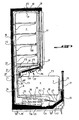
- the refrigerating cabinet comprises a lower part forming a tray 1 and an upper part forming a cupboard 2.
- the tray 1 is open upwards and delimited by a bottom wall 5, a rear wall 6 and a front wall 7, the side wall being removed to make visible the particular internal structure of the furniture.
- the cupboard whose left side wall is also omitted, is delimited at the rear by a wall 8, at the top by a wall 9, at the bottom by a bottom wall 10 which is part of a functional unit which is designated by the general reference 12.
- the closet is provided with means allowing access to its interior, such as doors.
- the furniture comprises a frame forming the U-shaped outer envelope, which comprises a base 16 provided with feet 16 'through which the furniture rests on the ground, a common rear wall and a roof wall 19 and side walls not shown.
- the front of the cabinet is formed by a piece of framing wall before 20 extended by an insert wall 21 advantageously transparent.
- the refrigerating cabinet is equipped with a cooling system by forced flow of a cold fluid, which comprises a cold source such as an evaporator 23 disposed in the space 25 between the bottom wall 5 in the form of a plate or plate of the tank and the base wall 16, and a fan device 24 placed in the same space between the evaporator 23 and the front wall 20, as well as flow paths of the cold fluid, clearly emerging from the figure 4 which illustrates the flow of cold fluid by arrow lines.
- a cold fluid which comprises a cold source such as an evaporator 23 disposed in the space 25 between the bottom wall 5 in the form of a plate or plate of the tank and the base wall 16, and a fan device 24 placed in the same space between the evaporator 23 and the front wall 20, as well as flow paths of the cold fluid, clearly emerging from the figure 4 which illustrates the flow of cold fluid by arrow lines.
- the flow paths of the cooling fluid are configured so that a cooling fluid envelope is obtained around the part of the tank 1 and of the cupboard 2, continuously along the entire length of the piece of furniture, between the back and the front of the furniture, inside of it.
- the invention provides a space 17 between the common rear wall or frame 18, on the one hand, and the rear wall 8 of the cabinet 2 and a vertical extension wall 26 which extends to in the bottom space 25 in which is housed the evaporator 23, on the other hand.
- These walls are formed by partitions in the form of plates.
- This gap space 17 which extends over the entire length and height at the rear of the cabinet communicates at the top with a space 28 delimited between the roof wall 19 and the upper partition wall 9 of the closet 2.
- This space rear space communicates down with the space 25 which houses the evaporator 23.
- the space 28 at the top of the cabinet opens in the internal space of the cupboard at the front end of the shelves 30 of exposure of foodstuffs, so that a vertical curtain of cold fluid can be established between the doors of the cabinet and the front of the shelves, that is to say in the interval 31.
- the functional device 12 comprises flow path spaces which allow a crossing of the two fluid flows, one for the return of the fluid having formed the curtain in the space 31 and symbolized by the arrow line F2 and the other symbolized by the arrow line F3, which is intended to cool the tank 1 by passing over the opening thereof, then to return to the housing space of the fans 24 and the evaporator 23, to through the gap space 33 delimited between the front wall 7 of the tank and the front wall 20 and front 21.
- the return path of the fluid F2 downstream of the device 12 is formed by the space 34 between the partition 26 of extension of the rear wall 8 of the cabinet and the rear wall 6 of the tank and the space 35 delimited between the bottom wall 5 of the tank and a partition 37 which is disposed above the evaporator 23, extends to the rear to the vertical partition 26 and is extended at the front by a partition wall 39.
- the latter extends to the front and is pierced by a plurality of openings 40 at a time of passage of the return fluid F2 cooling of the cabinet and cooling return fluid F3 of the tray, the latter after being passed through an interval 42 between the front wall 20 of the cabinet and a partition wall 43 which protrudes vertically downwards from the bottom plate 5 of the tray.
- This wall 43 has an important function because it makes it possible to adjust the proportion of the airflows F2 and F3, the total flow F1 being determined by the fans 24.
- This bottom wall rests on a support bar 45 indicated on the left on the figure 1 where the bottom wall 10 has been removed.
- the functional assembly 12 comprises, beneath the wall or bottom plate 10, at a predetermined distance, a plate-like wall wall 47, which is inclined with respect to the plate 10 so that the gap between the two plates increase toward the back of the cabinet.
- the plate 47 extends from the front of the access door frame indicated at 48, thereby closing the curtain space 31 down to the wall wall 26, which is arranged in the extension of the rear wall 8 of the cabinet leaving between these two plates, a gap 51 which establishes a communication between zones 50 in the form of channels in the internal space between the two plates 10 and 47 and the rear space 17 delimited between the back wall 18 and the partitions 8 and 26.
- the closet bottom plate 10 terminates at the front at a distance from the front edge of the lower plate 47 so as to leave a passage occupied by a grid 53 extending over the entire length of the furniture and allowing the flow F2 of the curtain space 31 to flow in a number of channels 56 established in the space between the two plates.
- These channels 56 are formed by mounting trapezoidal boxes also noted 56 which extend from a location back from the front edge of the plate 47, to the bottom wall 8 where they are closed, narrowing in width but by increasing in height since their upper faces extend horizontally and serve as support faces to the closet bottom plate 10.
- the boxes 56 open at the front and closed at the rear communicate with the space 34 delimited between the partitions 26 and 6 by windows 57 cut in the plate 47 at the closed rear end of the trapezoidal boxes 56.
- a number of trapezoidal boxes 56 are provided along the furniture on the plate 47, at predetermined distances from each other.
- the boxes are formed by sheet metal parts whose edges are folded perpendicular to their sides and at the rear end to form the side and rear walls and are mounted on the plate 47 in any appropriate known manner, for example using quote. But the boxes could also be advantageously made of plastic or with another material more insulating than the sheet.
- the advantages are thermal, ie better insulation between F2 and F3, and industrial, because these materials can be thermoformed or molded.
- each channel 50 and trapezoidal shape comprises in its middle part a perforation zone 60 through which the channel communicates with a flow collector box 62 which is mounted under the plate 47 and extends over the entire length thereof.
- This box is closed at its rear end 63 and open at its front end provided with a grid 64.
- the channels 50 and the box 62 allow the deflection of a portion of the cold fluid F1 from the evaporator 23, which constitutes the cooling flow F3 of the tank 1.
- a plate 66 for guiding the flow F3 towards the rear wall 6 where a louver device 67 with guide elements 68 in the shape of an L redirects the flow so that it flows. forwardly along the opening of the tray and be sucked into the bottom space 25 then passing through the gap space 33.
- the guide plate 66 extends, as the plate 47, to the front to the structure of the front wall of the facade being inclined downwards towards the wall 6.
- the shutter device 67 interposed between the partition 6 and the plate 66 has a plurality of angle-shaped elements 68 extending horizontally along the entire length of the furniture, parallel to each other, being offset in the direction of translation, with one branch, namely the branch 69 extending vertically and the other branch 70 located below the free horizontal edge 71 of the branch 69 extending horizontally.
- two adjacent angles 68 delimit between them a channel 72 in the form of an L-shaped slot which communicates at its upper end 73 with the space 74 delimited between the plates 47 and 66 and opening at its other end. 75 in the space above the bin 1.
- each channel 72 can drive a portion of the fluid F2 from the space 74 to the tray 1.
- the channels 72 between the louvers have the same outlet area 75 but different entrance areas 73, which can be chosen to increase from the rear end of the plate 66 towards the wall back 6 of the tray. More generally, depending on the input area of the channels and therefore the amount of air captured, it is possible to control the profile of the speed at the exit of the louver device.
- the flow F2 flows through the functional unit 12 through the channels formed by the trapezoidal boxes 56 in the space 34 through the openings 57 between the wall 26 and the rear wall 6 of the tank, and through the openings 40 in the partition 39 in the accommodating space 25 of the fans 24 and the evaporator 23.
- the flow F3 passes through the channels 50 delimited between the bottom plate 10 of the cupboard, the plate 47 and the box 62 communicating with these channels through the perforation zone 60, "crosses" the flow F2 through the different flow channels of the flows and succeeds, along the plate 66, through the louver device 67 in the space above the tray 1. Then, after having passed along the opening of the tray, it returns through the space 33 at the front of the cabinet front in the space 25 housing fans and the evaporator, after passing through the openings 40.
- the figures 5 and 6 illustrate two further advantageous measures of the invention.
- the figure 5 illustrates the advantage of the location of a lighting tube 77 under the wall 66, that is to say above the rear portion of the tray. Arranged in this way, it allows better lighting products, especially those located in the rear. Since this rear part of the tank is the coldest part, the thermal effect of the tube is practically negligible. Regarding the products at the front of the tray, they are well lit by the mood lighting of the store.
- the figure 6 illustrates an advantageous possibility of equipping the furniture with a night curtain designated by the reference 78, which is manually operable and extends between the lower end of the front facade of the cupboard 2 and the upper edge of the front wall 21 of the tray thus being able to cover the access opening to the tray.
- a night curtain designated by the reference 78
- the specific presence and location of the curtain or a plurality of side curtains juxtaposed have the advantages that the contact between the outside air and the protective curtain is minimized and the amount of fabric required is also reduced to a minimum. is of course advantageous from the thermal and economic point of view.
- the cooling fluid envelops the tray and the cupboard continuously over the entire length of the furniture, from the bottom at the top and from the top to the bottom at the front and at the back as well in the tank part as in the cupboard part. Since the flow encounters only the lowest flow resistance possible, its circulation can be provided by a single fan device 24 disposed in the bottom of the cabinet, that is to say in the space housing of the evaporator, between it and the front wall.
- both the flow channels F3 of the tank cooling flow F3 and the channels 56 of the cooling flow F2 of the cabinet open in spaces which extend, continuously, over the entire length for thus to restore the uniformity of the flow over the entire length and the envelope character of the flows over the entire length of the furniture, the flow F2 in the space 34 between the rear wall 6 of the tank and the partition wall 26 and the flow F2 in the box 62 below the plate 47 and the space above the plate 66. Because the flow flow paths are thus formed so as to oppose only a minimum of resistance to cooling flows it is possible to prevent fans from being located elsewhere than at the bottom of the cabinet.
Landscapes
- Engineering & Computer Science (AREA)
- Physics & Mathematics (AREA)
- Thermal Sciences (AREA)
- Chemical & Material Sciences (AREA)
- Combustion & Propulsion (AREA)
- Mechanical Engineering (AREA)
- General Engineering & Computer Science (AREA)
- Devices That Are Associated With Refrigeration Equipment (AREA)
Claims (11)
- Kühlmöbel, das einen unteren, truhenförmigen Warenraum, einen oberen, schrankförmigen Warenraum und ein Kühlsystem der Truhe und des Schrank durch erzwungenes Fließen eines Kühlfluids unter Einwirkung von Ventilatormitteln umfasst, wobei das System eine Kältequelle wie einen Verdampfer (23) aufweist, der im Boden des Truhenteils angeordnet ist, dadurch gekennzeichnet, dass das Kühlsystem Fließräume des Kühlfluids (17, 28, 31, 50, 56, 34, 35, 33, 25) aufweist, die sich um die Truhe (1) und den Schrank (2) über die gesamte Länge des Möbels derart erstrecken, um das Fließen des Kühlfluids abzusichern, das die Truhe und den Schrank über die gesamte Länge des Möbels umhüllt, und dass sich Kühlfluid-Fließwege des Schranks (2) und der Truhe (1) in dem Teil (12) des Möbels kreuzen, der sich zwischen dem Schrank und der Truhe befindet, wobei gleichzeitiger eine Verteilung der Ströme über die gesamte Länge des Möbels gewährleistet wird.
- Möbel nach Anspruch 1, dadurch gekennzeichnet, dass die Kreuzungszone der Kühlströme (F3, F2) der Truhe (1) und des Schranks (2) Fließkanäle (56, 50) der Kühlströme (F2) des Schranks und der Truhe (F3) aufweist, die über die Länge des Möbels alternierend nebeneinander liegen.
- Möbel nach Anspruch 2, dadurch gekennzeichnet, dass es einen Fluid-Fließraum (17) umfasst, der zwischen der gemeinsamen Skelett-Rückwand (18) des Möbels und den hinteren Trennwänden (8, 26) des Schranks und der Truhe begrenzt ist, wobei er sich über die gesamte Höhe und die gesamte Länge des Möbels erstreckt, wobei er oben mit einem Fließraum (28) kommuniziert, der sich zwischen der Dachwand (19) des Möbels und der oberen Trennwand (9) des Schranks (2) von hinten nach vorn im Verhältnis zu Möbel und über die gesamte Länge desselben erstreckt, und unten mit einem Raum (25), der sich unter der Bodentrennwand (5) der Truhe befindet, von hinten nach vorn, ebenfalls über die gesamte Länge des Möbels, wobei dieser Raum (25) die Kältequelle (23) und die Ventilatormittel (24) aufnimmt, und einem Fließraum (31) vor den Regalen (30) des Schranks, der dazu bestimmt ist, einen Kühlfluidvorhang vor diesen auszubilden.
- Möbel nach Anspruch 3, dadurch gekennzeichnet, dass die Kreuzungszone (12) der Kühlströme des Schranks und der Truhe Kanäle (50) aufweist, die mit dem vorgenannten hinteren Raum (17) kommunizieren und weiter vorn im Möbel mit Sammlermitteln (62), die sich kontinuierlich über die gesamte Länge des Möbels erstrecken und mit denen Rückleitungsmittel (66, 67) des Kühlstroms (F3) der Truhe (1) in Richtung der hinteren Trennwand (6) der Truhe und zur Umlenkung des Stroms (F3) derart angeordnet sind, dass dieser über und entlang der Öffnung in der Truhe nach oben bis zur Vorderwand (20, 21) der Truhe fließt, um danach von den Ventilatormitteln (24) im Bodenraum (25) des Möbels angesaugt zu werden.
- Möbel nach einem der Ansprüche 3 oder 4, dadurch gekennzeichnet, dass die Fließkanäle (56) des Kühlstroms (F2) des Schranks (1) vorn mit dem Raum (31), der vor den Regalen (30) ausgebildet ist, und einem Raum (34), der zwischen der hinteren Trennwand (6) der Truhe (1) und der begrenzenden Trennwand (26) des hinteren Raums (17) begrenzt ist, kommunizieren, wobei sich dieser Raum bis unter die Bodenwand (5) der Truhe erstreckt, wo er mit einem Raum (35) unter dieser Wand kommuniziert, der in der Anordnungszone der Ventilatormittel (24) mit einem Aufnahmeraum (25) der Kältequelle (23) kommuniziert.
- Möbel nach Anspruch 5, dadurch gekennzeichnet, dass die Rückleitungsmittel des Kühlstroms (F3) der Truhe (1) und zur Umleitung desselben eine nach hinten und unten geneigte Wand (66) zur Führung des Stroms, der aus dem Ausgangsstromsammler (62) der Kanäle (50) des Kühlstroms (F3) der Truhe austritt, aufweisen.
- Möbel nach einem der Ansprüche 5 oder 6, dadurch gekennzeichnet, dass Umleitungsmittel des Kühlstroms (F3) der Truhe nach vorn in Form einer Fensterladenvorrichtung (67) ausgebildet sind, die gegebenenfalls konfiguriert ist, um eine Steuerung der Fließgeschwindigkeit des Kühlstroms der Truhe über der Öffnung derselben in einer vertikalen Ebene zu erlauben.
- Möbel nach Anspruch 7, dadurch gekennzeichnet, dass die Fensterladenvorrichtung (67) eine Vielzahl paralleler Kanäle (72) aufweist, die sich über die gesamte Länge des Möbels erstrecken, die am Ausgang (75) etwa dieselben Fließbereiche aufweisen, aber deren Eingangsbereiche (73) in Abhängigkeit von der Fließgeschwindigkeit des Kühlfluids (F3), die man am Ausgang der Kanäle zu erhalten wünscht, abweichen.
- Möbel nach einem der Ansprüche 1 bis 8, dadurch gekennzeichnet, dass es eine Lichtquelle wie eine Leuchtröhre (77) aufweist, die über dem hinteren Teil der Truhe (1) angeordnet ist.
- Möbel nach einem der Ansprüche 1 bis 9, dadurch gekennzeichnet, dass es einen Nachtvorhang (78) umfasst, der sich von unteren Ende der Vorderseite des Schranks bis zur oberen Kante der vorderen Fassadenwand (21) der Truhe erstreckt.
- Möbel nach einem der Ansprüche 1 bis 10, dadurch gekennzeichnet, dass die Fließräume des Kühlfluids einen Raum (17) haben, der sich hinten im Möbel in Richtung eines Dachs (19) des Möbels erstreckt und in dem sich das fließende Fluid, das von der Kältequelle kommt, auf Ebene eines Intervalls (51) zwischen einer hinteren Wand (26) der Truhe und einer hinteren Wand (8) des Schranks trennt, indem es separate Kühlströme bildet, die einerseits einen Kühlstrom (F3) der Truhe und andererseits einen Kühlstrom (F2) des Schranks bilden, der bis zum Dach (19) aufsteigt, an diesem bis zur Vorderseite des Möbels in einen Raum (28) fließt, vor den Regalen hinabfließt, indem er vor diesen in einem Raum (31) einen Kühlvorhang bildet.
Applications Claiming Priority (1)
| Application Number | Priority Date | Filing Date | Title |
|---|---|---|---|
| FR0506709A FR2887969B1 (fr) | 2005-06-30 | 2005-06-30 | Meuble frigorifique, comprenant une partie inferieure formant un bac ouvert en haut et une partie superieure en forme de placard |
Publications (2)
| Publication Number | Publication Date |
|---|---|
| EP1741999A1 EP1741999A1 (de) | 2007-01-10 |
| EP1741999B1 true EP1741999B1 (de) | 2013-05-08 |
Family
ID=35628874
Family Applications (1)
| Application Number | Title | Priority Date | Filing Date |
|---|---|---|---|
| EP20060291028 Not-in-force EP1741999B1 (de) | 2005-06-30 | 2006-06-22 | Kühlmöbel mit einem unteren, truhenförmigen Warenraum und einem oberen, schrankförmigen Warenraum |
Country Status (3)
| Country | Link |
|---|---|
| EP (1) | EP1741999B1 (de) |
| DK (1) | DK1741999T3 (de) |
| FR (1) | FR2887969B1 (de) |
Families Citing this family (4)
| Publication number | Priority date | Publication date | Assignee | Title |
|---|---|---|---|---|
| GB2445425A (en) * | 2007-01-06 | 2008-07-09 | Ian Garvey | Refrigerated Display Cabinet with a Cooled Bifurcated Air Flow |
| ATE543061T1 (de) * | 2008-02-22 | 2012-02-15 | Epta Spa | Horizontales gekühltes anzeigegehäuse für bedienung oder selbstbedienung |
| JP5586535B2 (ja) * | 2011-07-14 | 2014-09-10 | 三菱電機株式会社 | 冷蔵庫 |
| WO2022148988A1 (ru) * | 2021-01-06 | 2022-07-14 | Юрий ХАРЧЕНКО | Комбинированная холодильная установка |
Family Cites Families (4)
| Publication number | Priority date | Publication date | Assignee | Title |
|---|---|---|---|---|
| DE4000713A1 (de) * | 1990-01-12 | 1991-07-18 | Linde Ag | Verkaufskuehlmoebel |
| US5675983A (en) * | 1996-09-11 | 1997-10-14 | Kysor Industrial Corporation | Synergistic refrigerated display case |
| DE10048490A1 (de) * | 2000-09-29 | 2002-04-11 | Linde Ag | Verkaufs(tief)kühlmöbel |
| ITUD20040070A1 (it) * | 2004-04-08 | 2004-07-08 | Ind Scaffalature Arredamenti I | Espositore refrigerato a doppia vasca |
-
2005
- 2005-06-30 FR FR0506709A patent/FR2887969B1/fr not_active Expired - Fee Related
-
2006
- 2006-06-22 EP EP20060291028 patent/EP1741999B1/de not_active Not-in-force
- 2006-06-22 DK DK06291028T patent/DK1741999T3/da active
Also Published As
| Publication number | Publication date |
|---|---|
| DK1741999T3 (da) | 2013-06-03 |
| EP1741999A1 (de) | 2007-01-10 |
| FR2887969B1 (fr) | 2007-10-12 |
| FR2887969A1 (fr) | 2007-01-05 |
Similar Documents
| Publication | Publication Date | Title |
|---|---|---|
| KR101876581B1 (ko) | 개선된 냉장 디스플레이 기기 | |
| EP1741999B1 (de) | Kühlmöbel mit einem unteren, truhenförmigen Warenraum und einem oberen, schrankförmigen Warenraum | |
| ES2641563T3 (es) | Mejoras en o relativas a dispositivos de muestra refrigerados | |
| EP3612063B1 (de) | Schrank mit gehäusen zum halten von lebensmitteln bei warmen temperaturen | |
| FR2676800A1 (fr) | Armoire chauffante de laboratoire et/ou armoire de climatisation avec des ecarts de temperature les plus reduits possibles. | |
| EP1414327B1 (de) | Gekühlte auslage, insbesondere vertikale auslage, mit vorderem kühlluftvorhang | |
| FR2994374A1 (fr) | Installation pour rafraichir des articles exposes a la vente par un brouillard de gouttelettes d'eau | |
| AU7216301A (en) | Display showcase for fresh merchandise, such as fresh bread, cakes and pastries | |
| EP1713358B1 (de) | Gefriereinrichtung und einsatz dafür | |
| EP1344986A1 (de) | Ofen mit Gebläse | |
| FR2614090A3 (fr) | Appareil mobile de climatisation de locaux | |
| EP1580488A1 (de) | Interne Ventilation in einem Mikrowellenofen | |
| EP2672191A1 (de) | Kondenswasserbehälter und Luftaufbereitungsgerät, das mit einem solchen Behälter ausgestattet ist | |
| EP2309833B1 (de) | Module für Netzwerk- und Serverschränke, und ihr Einbau | |
| EP2977687B1 (de) | Kühl-, klimatisierungs- oder heizsystem mit getrennten einheiten, und gehäuse mit einer der einheiten | |
| EP2862484B1 (de) | Belüftetes Kühlregal | |
| FR2981735A1 (fr) | Dispositif generant un rideau d'air dans la baie d'acces a une enceinte de conservation | |
| FR2682560A1 (fr) | Four de cuisson a enceinte de cuisson et chargeur amovible. | |
| FR2808080A1 (fr) | Dispositif pour optimiser la surgelation en continu de produits en vrac, individuellement, une installation equipee dudit dispositif et application dudit dispositif | |
| FR2467548A1 (fr) | Procede de fabrication d'un four et four de boulangerie obtenu par ce procede | |
| EP1543749A1 (de) | Kühltheke | |
| JP2011078652A (ja) | ショーケース | |
| FR2586546A1 (fr) | Meuble climatise pour l'offre de produits a la vente | |
| EP4040052A1 (de) | System mit heizmodulsatz | |
| CH269612A (fr) | Vitrine réfrigérée pour la conservation, l'exposition et le débit de glaces ou autres denrées périssables. |
Legal Events
| Date | Code | Title | Description |
|---|---|---|---|
| PUAI | Public reference made under article 153(3) epc to a published international application that has entered the european phase |
Free format text: ORIGINAL CODE: 0009012 |
|
| AK | Designated contracting states |
Kind code of ref document: A1 Designated state(s): AT BE BG CH CY CZ DE DK EE ES FI FR GB GR HU IE IS IT LI LT LU LV MC NL PL PT RO SE SI SK TR |
|
| AX | Request for extension of the european patent |
Extension state: AL BA HR MK YU |
|
| 17P | Request for examination filed |
Effective date: 20070702 |
|
| 17Q | First examination report despatched |
Effective date: 20070802 |
|
| AKX | Designation fees paid |
Designated state(s): AT BE BG CH CY CZ DE DK EE ES FI FR GB GR HU IE IS IT LI LT LU LV MC NL PL PT RO SE SI SK TR |
|
| GRAP | Despatch of communication of intention to grant a patent |
Free format text: ORIGINAL CODE: EPIDOSNIGR1 |
|
| GRAS | Grant fee paid |
Free format text: ORIGINAL CODE: EPIDOSNIGR3 |
|
| GRAA | (expected) grant |
Free format text: ORIGINAL CODE: 0009210 |
|
| AK | Designated contracting states |
Kind code of ref document: B1 Designated state(s): AT BE BG CH CY CZ DE DK EE ES FI FR GB GR HU IE IS IT LI LT LU LV MC NL PL PT RO SE SI SK TR |
|
| REG | Reference to a national code |
Ref country code: GB Ref legal event code: FG4D Free format text: NOT ENGLISH |
|
| REG | Reference to a national code |
Ref country code: CH Ref legal event code: EP Ref country code: AT Ref legal event code: REF Ref document number: 611284 Country of ref document: AT Kind code of ref document: T Effective date: 20130515 |
|
| REG | Reference to a national code |
Ref country code: DK Ref legal event code: T3 |
|
| REG | Reference to a national code |
Ref country code: IE Ref legal event code: FG4D Free format text: LANGUAGE OF EP DOCUMENT: FRENCH |
|
| REG | Reference to a national code |
Ref country code: DE Ref legal event code: R096 Ref document number: 602006036146 Country of ref document: DE Effective date: 20130704 |
|
| REG | Reference to a national code |
Ref country code: AT Ref legal event code: MK05 Ref document number: 611284 Country of ref document: AT Kind code of ref document: T Effective date: 20130508 |
|
| REG | Reference to a national code |
Ref country code: LT Ref legal event code: MG4D |
|
| REG | Reference to a national code |
Ref country code: NL Ref legal event code: VDEP Effective date: 20130508 |
|
| PG25 | Lapsed in a contracting state [announced via postgrant information from national office to epo] |
Ref country code: GR Free format text: LAPSE BECAUSE OF FAILURE TO SUBMIT A TRANSLATION OF THE DESCRIPTION OR TO PAY THE FEE WITHIN THE PRESCRIBED TIME-LIMIT Effective date: 20130809 Ref country code: LT Free format text: LAPSE BECAUSE OF FAILURE TO SUBMIT A TRANSLATION OF THE DESCRIPTION OR TO PAY THE FEE WITHIN THE PRESCRIBED TIME-LIMIT Effective date: 20130508 Ref country code: PT Free format text: LAPSE BECAUSE OF FAILURE TO SUBMIT A TRANSLATION OF THE DESCRIPTION OR TO PAY THE FEE WITHIN THE PRESCRIBED TIME-LIMIT Effective date: 20130909 Ref country code: IS Free format text: LAPSE BECAUSE OF FAILURE TO SUBMIT A TRANSLATION OF THE DESCRIPTION OR TO PAY THE FEE WITHIN THE PRESCRIBED TIME-LIMIT Effective date: 20130908 Ref country code: SE Free format text: LAPSE BECAUSE OF FAILURE TO SUBMIT A TRANSLATION OF THE DESCRIPTION OR TO PAY THE FEE WITHIN THE PRESCRIBED TIME-LIMIT Effective date: 20130508 Ref country code: FI Free format text: LAPSE BECAUSE OF FAILURE TO SUBMIT A TRANSLATION OF THE DESCRIPTION OR TO PAY THE FEE WITHIN THE PRESCRIBED TIME-LIMIT Effective date: 20130508 Ref country code: ES Free format text: LAPSE BECAUSE OF FAILURE TO SUBMIT A TRANSLATION OF THE DESCRIPTION OR TO PAY THE FEE WITHIN THE PRESCRIBED TIME-LIMIT Effective date: 20130819 Ref country code: AT Free format text: LAPSE BECAUSE OF FAILURE TO SUBMIT A TRANSLATION OF THE DESCRIPTION OR TO PAY THE FEE WITHIN THE PRESCRIBED TIME-LIMIT Effective date: 20130508 Ref country code: SI Free format text: LAPSE BECAUSE OF FAILURE TO SUBMIT A TRANSLATION OF THE DESCRIPTION OR TO PAY THE FEE WITHIN THE PRESCRIBED TIME-LIMIT Effective date: 20130508 |
|
| PGFP | Annual fee paid to national office [announced via postgrant information from national office to epo] |
Ref country code: DK Payment date: 20130701 Year of fee payment: 8 Ref country code: BE Payment date: 20130731 Year of fee payment: 8 Ref country code: IE Payment date: 20130701 Year of fee payment: 8 Ref country code: DE Payment date: 20130902 Year of fee payment: 8 |
|
| PG25 | Lapsed in a contracting state [announced via postgrant information from national office to epo] |
Ref country code: BG Free format text: LAPSE BECAUSE OF FAILURE TO SUBMIT A TRANSLATION OF THE DESCRIPTION OR TO PAY THE FEE WITHIN THE PRESCRIBED TIME-LIMIT Effective date: 20130808 Ref country code: PL Free format text: LAPSE BECAUSE OF FAILURE TO SUBMIT A TRANSLATION OF THE DESCRIPTION OR TO PAY THE FEE WITHIN THE PRESCRIBED TIME-LIMIT Effective date: 20130508 Ref country code: CY Free format text: LAPSE BECAUSE OF FAILURE TO SUBMIT A TRANSLATION OF THE DESCRIPTION OR TO PAY THE FEE WITHIN THE PRESCRIBED TIME-LIMIT Effective date: 20130508 |
|
| PGFP | Annual fee paid to national office [announced via postgrant information from national office to epo] |
Ref country code: FR Payment date: 20130719 Year of fee payment: 8 Ref country code: GB Payment date: 20130701 Year of fee payment: 8 |
|
| PG25 | Lapsed in a contracting state [announced via postgrant information from national office to epo] |
Ref country code: LV Free format text: LAPSE BECAUSE OF FAILURE TO SUBMIT A TRANSLATION OF THE DESCRIPTION OR TO PAY THE FEE WITHIN THE PRESCRIBED TIME-LIMIT Effective date: 20130508 |
|
| PG25 | Lapsed in a contracting state [announced via postgrant information from national office to epo] |
Ref country code: SK Free format text: LAPSE BECAUSE OF FAILURE TO SUBMIT A TRANSLATION OF THE DESCRIPTION OR TO PAY THE FEE WITHIN THE PRESCRIBED TIME-LIMIT Effective date: 20130508 Ref country code: CZ Free format text: LAPSE BECAUSE OF FAILURE TO SUBMIT A TRANSLATION OF THE DESCRIPTION OR TO PAY THE FEE WITHIN THE PRESCRIBED TIME-LIMIT Effective date: 20130508 Ref country code: EE Free format text: LAPSE BECAUSE OF FAILURE TO SUBMIT A TRANSLATION OF THE DESCRIPTION OR TO PAY THE FEE WITHIN THE PRESCRIBED TIME-LIMIT Effective date: 20130508 |
|
| REG | Reference to a national code |
Ref country code: CH Ref legal event code: PL |
|
| PG25 | Lapsed in a contracting state [announced via postgrant information from national office to epo] |
Ref country code: NL Free format text: LAPSE BECAUSE OF FAILURE TO SUBMIT A TRANSLATION OF THE DESCRIPTION OR TO PAY THE FEE WITHIN THE PRESCRIBED TIME-LIMIT Effective date: 20130508 Ref country code: IT Free format text: LAPSE BECAUSE OF FAILURE TO SUBMIT A TRANSLATION OF THE DESCRIPTION OR TO PAY THE FEE WITHIN THE PRESCRIBED TIME-LIMIT Effective date: 20130508 Ref country code: RO Free format text: LAPSE BECAUSE OF FAILURE TO SUBMIT A TRANSLATION OF THE DESCRIPTION OR TO PAY THE FEE WITHIN THE PRESCRIBED TIME-LIMIT Effective date: 20130508 Ref country code: MC Free format text: LAPSE BECAUSE OF FAILURE TO SUBMIT A TRANSLATION OF THE DESCRIPTION OR TO PAY THE FEE WITHIN THE PRESCRIBED TIME-LIMIT Effective date: 20130508 |
|
| PLBE | No opposition filed within time limit |
Free format text: ORIGINAL CODE: 0009261 |
|
| STAA | Information on the status of an ep patent application or granted ep patent |
Free format text: STATUS: NO OPPOSITION FILED WITHIN TIME LIMIT |
|
| 26N | No opposition filed |
Effective date: 20140211 |
|
| PG25 | Lapsed in a contracting state [announced via postgrant information from national office to epo] |
Ref country code: CH Free format text: LAPSE BECAUSE OF NON-PAYMENT OF DUE FEES Effective date: 20130630 Ref country code: LI Free format text: LAPSE BECAUSE OF NON-PAYMENT OF DUE FEES Effective date: 20130630 |
|
| REG | Reference to a national code |
Ref country code: DE Ref legal event code: R097 Ref document number: 602006036146 Country of ref document: DE Effective date: 20140211 |
|
| REG | Reference to a national code |
Ref country code: DE Ref legal event code: R119 Ref document number: 602006036146 Country of ref document: DE |
|
| REG | Reference to a national code |
Ref country code: DK Ref legal event code: EBP Effective date: 20140630 |
|
| GBPC | Gb: european patent ceased through non-payment of renewal fee |
Effective date: 20140622 |
|
| REG | Reference to a national code |
Ref country code: IE Ref legal event code: MM4A |
|
| REG | Reference to a national code |
Ref country code: DE Ref legal event code: R119 Ref document number: 602006036146 Country of ref document: DE Effective date: 20150101 |
|
| REG | Reference to a national code |
Ref country code: FR Ref legal event code: ST Effective date: 20150227 |
|
| PG25 | Lapsed in a contracting state [announced via postgrant information from national office to epo] |
Ref country code: DE Free format text: LAPSE BECAUSE OF NON-PAYMENT OF DUE FEES Effective date: 20150101 Ref country code: IE Free format text: LAPSE BECAUSE OF NON-PAYMENT OF DUE FEES Effective date: 20140622 |
|
| PG25 | Lapsed in a contracting state [announced via postgrant information from national office to epo] |
Ref country code: FR Free format text: LAPSE BECAUSE OF NON-PAYMENT OF DUE FEES Effective date: 20140630 Ref country code: GB Free format text: LAPSE BECAUSE OF NON-PAYMENT OF DUE FEES Effective date: 20140622 |
|
| PG25 | Lapsed in a contracting state [announced via postgrant information from national office to epo] |
Ref country code: TR Free format text: LAPSE BECAUSE OF FAILURE TO SUBMIT A TRANSLATION OF THE DESCRIPTION OR TO PAY THE FEE WITHIN THE PRESCRIBED TIME-LIMIT Effective date: 20130508 |
|
| PG25 | Lapsed in a contracting state [announced via postgrant information from national office to epo] |
Ref country code: DK Free format text: LAPSE BECAUSE OF NON-PAYMENT OF DUE FEES Effective date: 20140630 Ref country code: HU Free format text: LAPSE BECAUSE OF FAILURE TO SUBMIT A TRANSLATION OF THE DESCRIPTION OR TO PAY THE FEE WITHIN THE PRESCRIBED TIME-LIMIT; INVALID AB INITIO Effective date: 20060622 Ref country code: LU Free format text: LAPSE BECAUSE OF NON-PAYMENT OF DUE FEES Effective date: 20130622 |
|
| PG25 | Lapsed in a contracting state [announced via postgrant information from national office to epo] |
Ref country code: BE Free format text: LAPSE BECAUSE OF NON-PAYMENT OF DUE FEES Effective date: 20140630 |