EP1741644B1 - Article storage facility - Google Patents
Article storage facility Download PDFInfo
- Publication number
- EP1741644B1 EP1741644B1 EP06013757A EP06013757A EP1741644B1 EP 1741644 B1 EP1741644 B1 EP 1741644B1 EP 06013757 A EP06013757 A EP 06013757A EP 06013757 A EP06013757 A EP 06013757A EP 1741644 B1 EP1741644 B1 EP 1741644B1
- Authority
- EP
- European Patent Office
- Prior art keywords
- article
- movable bodies
- transfer
- storage
- rack
- Prior art date
- Legal status (The legal status is an assumption and is not a legal conclusion. Google has not performed a legal analysis and makes no representation as to the accuracy of the status listed.)
- Active
Links
- 238000010586 diagram Methods 0.000 description 5
- 238000001514 detection method Methods 0.000 description 4
- 238000000034 method Methods 0.000 description 2
- 230000000630 rising effect Effects 0.000 description 1
- 230000001360 synchronised effect Effects 0.000 description 1
Images


Classifications
-
- B—PERFORMING OPERATIONS; TRANSPORTING
- B65—CONVEYING; PACKING; STORING; HANDLING THIN OR FILAMENTARY MATERIAL
- B65G—TRANSPORT OR STORAGE DEVICES, e.g. CONVEYORS FOR LOADING OR TIPPING, SHOP CONVEYOR SYSTEMS OR PNEUMATIC TUBE CONVEYORS
- B65G1/00—Storing articles, individually or in orderly arrangement, in warehouses or magazines
- B65G1/02—Storage devices
- B65G1/04—Storage devices mechanical
- B65G1/0407—Storage devices mechanical using stacker cranes
- B65G1/0421—Storage devices mechanical using stacker cranes with control for stacker crane operations
-
- B—PERFORMING OPERATIONS; TRANSPORTING
- B65—CONVEYING; PACKING; STORING; HANDLING THIN OR FILAMENTARY MATERIAL
- B65G—TRANSPORT OR STORAGE DEVICES, e.g. CONVEYORS FOR LOADING OR TIPPING, SHOP CONVEYOR SYSTEMS OR PNEUMATIC TUBE CONVEYORS
- B65G1/00—Storing articles, individually or in orderly arrangement, in warehouses or magazines
- B65G1/02—Storage devices
- B65G1/04—Storage devices mechanical
- B65G1/12—Storage devices mechanical with separate article supports or holders movable in a closed circuit to facilitate insertion or removal of articles the articles being books, documents, forms or the like
-
- B—PERFORMING OPERATIONS; TRANSPORTING
- B66—HOISTING; LIFTING; HAULING
- B66F—HOISTING, LIFTING, HAULING OR PUSHING, NOT OTHERWISE PROVIDED FOR, e.g. DEVICES WHICH APPLY A LIFTING OR PUSHING FORCE DIRECTLY TO THE SURFACE OF A LOAD
- B66F9/00—Devices for lifting or lowering bulky or heavy goods for loading or unloading purposes
- B66F9/06—Devices for lifting or lowering bulky or heavy goods for loading or unloading purposes movable, with their loads, on wheels or the like, e.g. fork-lift trucks
- B66F9/07—Floor-to-roof stacking devices, e.g. "stacker cranes", "retrievers"
Definitions
- the present invention relates to an article storage facility comprising an article storage rack having a plurality of storage units, a movable body for conveying an article, and control means for controlling the actuation of the movable body.
- an article-conveying movable body conveys an article between an article storage rack and a loading/unloading article support unit. Warehousing is thereby performed in which an article present in the loading/unloading article support unit is stored by a storage unit of the article storage rack, or retrieval is performed in which an article stored in the storage unit of the article storage rack is retrieved to the loading/unloading article support unit.
- two article-conveying movable bodies are provided so as to move horizontally on the same track, and two loading/unloading article support units are provided so as to be disposed at both side branches of the article storage rack (see Japanese Laid-open Patent Application No. 2002-175117 , for example).
- one of the two movable bodies conveys an article between the article storage rack and one of the loading/unloading article support units
- the other movable body conveys an article between the article storage rack and the other loading/unloading article support unit
- the two movable bodies simultaneously perform article conveyance, whereby the ability to convey articles is enhanced.
- the document EP 1512661 A discloses a system with two stacker cranes, which are capable to operate in a synchronized manner.
- the present invention was developed in view of the issues described above, and an object thereof is to provide an article storage facility whereby the ability to convey articles can be enhanced.
- the article storage facility of the present invention comprises:
- the operation for conveying an article with one of two movable bodies that are adjacent to each other in the direction of horizontal movement can be performed simultaneously with the operation for conveying an article with the other movable body, and an article can therefore be conveyed efficiently using a plurality of movable bodies. It is thereby possible to provide an article storage facility having an enhanced article conveyance capacity.
- this article storage facility is composed of an article storage rack 2 provided with a plurality of storage units 1 arranged vertically and horizontally, and a stacker crane 4 as a movable body for conveying an article B between the article storage rack 2 and a loading/unloading article support unit 3.
- front and back pillars 5 are vertically arranged in a plurality of pairs at an interval in the horizontal direction, and a plurality of placement support units 6 extending in the horizontal direction is provided at an interval in the vertical direction to each pair of front and back pillars 5.
- One pair of front and back pillars 5 and one pair of left and right placement support units 6 form a single storage unit 1, and a plurality of storage units 1 is provided vertically and horizontally.
- Two article storage racks 2 are provided at an interval so as to face each other in the direction in which articles move in and out, and two loading/unloading article support units 3 are mounted at an interval so as to face each other at the sides of the article storage racks 2 and in other adjacent positions in the horizontal direction of the article storage rack 2.
- Each of the plurality of storage units 1 and each of the loading/unloading article support units 3 in the article storage rack 2 is configured as an article transfer location.
- a travel rail 7 is mounted on the floor surface between the two article storage racks 2 as a track that extends through the entire range of the horizontal direction of the article storage racks 2 to the loading/unloading article support units 3, and a guide rail 8 that extends through the entire range of the horizontal direction of the article storage racks 2 to the loading/unloading article support units 3 is mounted to the top side.
- a stacker crane 4 is provided so as to move horizontally on the travel rail 7 while being guided by the guide rail 8.
- a ground controller 9 for managing the operation of the stacker crane 4 is provided to the end on the side of the loading/unloading article support units 3 among the ends of the travel rail 7, and the ground controller 9 manages storage information such as which article is stored in which storage unit 1.
- each of the two stacker cranes 4 is composed of a horizontally movable traveling truck 10 that travels along the travel rail 7, a lift platform 11 capable of lifting and lowering with respect to the traveling truck 10, and a transfer device 12 (a fork-type transfer device, for example) as an article transfer means provided to the lift platform 11.
- a transfer device 12 a fork-type transfer device, for example
- any of the various known devices other than the fork type transfer device that has two pairs of arms are telescopically extended by a motor driven chain, may be employed.
- Another example of a transfer device is disclosed in US Patent Application Publication 2005/0036858A1 , which is incorporated herein by reference.
- the stacker cranes 4 are configured so as to store an article B present in the loading/unloading article support unit 3 in a storage unit 1 of the article storage rack 2, or to retrieve the article B stored in the storage unit 1 of the article storage rack 2 to the loading/unloading article support unit 3 by horizontal movement of the traveling trucks 10, vertical movement of the lift platforms 11, and transfer of the transfer devices 12.
- two receiving platforms 13 as loading/unloading article support units 3 onto which the article B is placed are arranged in the direction of horizontal movement of the stacker crane 4.
- the loading/unloading article support units 3 used for storage and retrieval are thus configured so that two stacker cranes 4 can be positioned along the direction of horizontal movement, and an article B can be transferred to and from a receiving platform 13 by the transfer devices 12 provided to each stacker crane 4.
- the stacker crane positioned on the side of the loading/unloading article support units 3 among the two stacker cranes 4 is designated as the first stacker crane 4a
- the stacker crane positioned on the side of the article storage rack 2 is designated as the second stacker crane 4b.
- the receiving platform positioned on the far side of the article storage racks 2 is designated as the first receiving platform 13a
- the receiving platform positioned on the near side of the article storage racks 2 is designated as the second receiving platform 13b.
- the first stacker crane 4a conveys an article between the first receiving platform 13a and the article storage racks 2
- the second stacker crane 4b conveys an article between the second receiving platform 13b and the article storage racks 2.
- a single vertical post 14 for guiding and supporting the lift platform 11 so as to allow the lift platform 11 to move up and down is vertically provided to the traveling truck 10, and the position in which this vertical post 14 is erected is substantially separated from the end portion 10a closer to the remaining single stacker crane 4 in the direction of horizontal movement of the stacker cranes 4.
- the position in which the vertical post 14 is erected may be on the opposite side from the side on which the remaining single stacker crane 4 is positioned in the direction of horizontal movement of the stacker cranes 4.
- the lift platforms 11 of the traveling trucks 10 each have an opposing face 11a closest to the adjacent traveling truck 10 in the direction of horizontal movement.
- the length L1 by which the end portion 10a closest to the adjacent traveling truck 10 protrudes from the reference surface S of the vertical post in the horizontal direction in each traveling truck 10 is smaller than the length L2 by which the opposing face 11a protrudes from the reference surface S in the horizontal direction.
- the length L1 is preferably 70% or less of the length L2.
- the lift platform 11 is suspended and supported by a lift chain 15.
- the lift chain 15 is suspended between a guide sprocket 17 provided to an upper frame 16 guided along the guide rail 8 and a guide sprocket 18 provided to the lower side of the vertical post 14, and is connected to a takeup drum 19 fitted to one end of the traveling truck 10.
- the takeup drum 19 is rotatably driven forward and backward by an inverter-type electric lift motor 20, and the lift platform 11 is raised and lowered by the outward and inward spooling of the lift chain 15.
- the lift platform 11 is provided with a lift rotary encoder 22 for detecting the vertical position of the lift platform 11 in the lift path.
- This lift rotary encoder 22 is not shown in detail in the drawing, but a sprocket for meshing with a chain laid in the vertical direction of the vertical post 14 is attached to the rotating shaft of the lift rotary encoder 22, the sprocket is rotated by the lifting of the lift platform 11, and the vertical position of the lift platform 11 is detected by detecting the lift distance of the lift platform 11 from a reference position set at the lower end portion of the lift path.
- Two wheels 24 front and back that can travel on the travel rail 7 are provided to the traveling truck 10.
- the wheel on one end in the direction of horizontal movement among the two wheels 24 is configured as a drive wheel 24a driven by an inverter-type electric travel motor 25, and the wheel on the other end in the direction of horizontal movement is configured as a free-rotating driven wheel 24b.
- the inverter-type electric travel motor 25 rotatably drives the drive wheel 24a forward and backward, whereby the traveling truck 10 is moved horizontally.
- a guide roller 21 capable of rotating about a horizontal axis is provided to the traveling truck 10 in each position in which the two wheels 24 (front and back) are disposed.
- the roller contacts the travel rail 7 so as to restrict upward movement, and for preventing the wheels 24 from lifting off of the travel rail 7.
- a travel rotary encoder 23 for detecting the travel position of the traveling truck 10 in the travel path is provided to the traveling truck 10.
- This travel rotary encoder 23 is not shown in detail in the drawing, but a sprocket for meshing with a chain laid along the travel rail 7 is attached to the rotating shaft of the travel rotary encoder 23, the sprocket is rotated by the horizontal movement of the traveling truck 10, and the travel position of the traveling truck 10 is detected by detecting the distance which the traveling truck 10 has moved horizontally from a reference position set at one end of the travel rail 7.
- the two stacker cranes 4 are configured so that the provided transfer devices 12 can be positioned in an overlapped state in the vertical direction.
- Each of the two stacker cranes 4 is also capable of positioning the provided transfer devices 12 in an overlapped state in the vertical direction by moving closer to the other stacker crane 4 adjacent in the direction of horizontal movement.
- Positioning the transfer devices 12 provided thereto in an overlapped state in the vertical direction in this manner allows the two stacker cranes 4 to transfer articles B simultaneously with respect to two storage units 1 having the same position in the horizontal direction of the rack and different positions in the vertical direction of the rack among the plurality of storage units 1 in the article storage rack 2.
- the position of the vertical post 14 in the horizontal direction in the traveling truck 10 is adjusted so that the traveling trucks 10 do not come in contact with each other, while the transfer devices 12 overlap each other in the vertical direction.
- the width of the upper frame 16 in the horizontal direction is also adjusted when the two stacker cranes 4 are in proximity to each other so that the upper frames 16 do not come in contact with each other, while the transfer devices 12 overlap each other in the horizontal direction.
- a crane control device 26 for controlling the operation of the stacker crane 4 is provided to each of the two stacker cranes 4.
- the crane control device 26 provided to the first stacker crane 4a is designated as the first crane control device 26A
- the crane control device 26 provided to the second stacker crane 4b is designated as the second crane control device 26B.
- the detection information of the lift rotary encoders 22 and the detection information of the travel rotary encoders 23 are inputted to the crane control devices 26.
- the first crane control device 26A and the second crane control device 26B have the same structure.
- the crane control devices 26 are configured so that the horizontal movement of the traveling trucks 10 and the vertical movement of the lift platforms 11 are controlled so as to move the transfer devices 12 to rack-side article transfer positions at each of the plurality of storage units 1, and to convey articles with controlled transfer of the transfer devices 12 so that the transfer devices 12 transfer articles to and from the storage units 1 and the loading/unloading article support units 3 in the rack-side article transfer positions and the loading/unloading-side article transfer position.
- the rack-side article transfer position and the loading/unloading-side article transfer position are positions measured from a lift target stopping position and a travel target stopping position.
- a loading/unloading-side article transfer position is determined for each of the two receiving platforms 13, and a lift target stopping position and a travel target stopping position are set for each of the two receiving platforms 13.
- An rack-side article transfer position is determined for each of the plurality of storage units 1, and a lift target stopping position and a travel target stopping position are set for each of the plurality of storage units 1.
- the crane control devices 26 are composed of a travel control unit 26a for controlling the horizontal movement of the traveling truck 10 so as to cause the traveling truck 10 to travel to a prescribed travel target stopping position based on the detection information of the travel rotary encoder 23, a lift control unit 26b for controlling the lift actuation of the lift platform 11 so as to cause the lift platform 11 to rise to a prescribed lift target stopping position based on the detection information of the lift rotary encoder 22, and a transfer control unit 26c for controlling the transfer of the transfer device 12 so that articles are transferred to and from the storage units 1 and the receiving platforms 13.
- the electric travel motor 25 is started to initiate horizontal movement of the traveling truck 10, and when the travel position of the traveling truck 10 detected by the travel rotary encoder 23 reaches the prescribed travel target stopping position, the electric travel motor 25 is stopped, a brake is applied, and operation of the electric travel motor 25 is controlled so that the traveling truck 10 is stopped in the travel target stopping position.
- the electric lift motor 20 is started to initiate vertical movement of the lift platform 11, and when the vertical position of the lift platform 11 detected by the lift rotary encoder 22 reaches the prescribed lift target stopping position, the electric lift motor 20 is stopped, a brake is applied, and operation of the electric lift motor 20 is controlled so that the lift platform 11 is stopped in the lift target stopping position.
- the fork-type transfer device 12 is started, and transfer of the transfer device 12 is controlled so that the fork is extended, the article B is loaded or unloaded, and the fork is then retracted.
- Various types of information can be transmitted between the crane control device 26 and the ground controller 9, and the ground controller 9 issues various types of instructions to the two crane control devices 26, which include the first crane control device 26A and the second crane control device 26B.
- the crane control devices 26 are configured so that travel control is performed by the travel control unit 26a, lift control is performed by the lift control unit 26b, and transfer control is performed by the transfer control unit 26c on the basis of instructions from the ground controller 9, whereby articles are conveyed.
- a control means H for controlling the operation of the plurality of stacker cranes 4 is thus composed of the ground controller 9 and two crane control devices 26.
- the control means H is configured so as to select both of the two stacker cranes 4 or one of the two stacker cranes 4 as an article-conveying stacker crane 4, and to perform an article conveyance operation based on article conveyance command information.
- control means H selects one of the two stacker cranes 4 as the article-conveying stacker crane 4, the control means H performs a selection operation for selecting the article-conveying stacker crane 4 among the two stacker cranes 4, and performs an article conveyance operation for causing the stacker crane 4 selected in the selection operation to convey the article.
- the stacker crane 4 that will convey the article is selected on the basis of whether the stacker crane 4 is currently conveying an article, what the current positions of the two stacker cranes 4 are, and other selection conditions. For example, when both of the two stacker cranes 4 are in the loading/unloading-side article transfer position, the second stacker crane 4b is selected as the stacker crane 4 that will convey the article.
- the control means H thus selectively executes a simultaneous storage operation, a first independent storage operation, a second independent storage operation, a simultaneous retrieval operation, a first independent retrieval operation, or a second independent retrieval operation based on article conveyance command information and selection conditions.
- the simultaneous storage operation and the simultaneous retrieval operation are article conveyance operations in which both of the two stacker cranes 4 are selected as stacker cranes that will convey an article.
- the first independent storage operation and the first independent retrieval operation are article conveyance operations in which the first stacker crane 4a among the two stacker cranes 4 is selected as the stacker crane that will convey an article.
- the second independent storage operation and the second independent retrieval operation are article conveyance operations in which the second stacker crane 4b among the two stacker cranes 4 is selected as the stacker crane that will convey an article.
- the flowchart in FIG. 5 will be used to describe which operation the control means H executes among the plurality of operations based on the article conveyance command information and the selection conditions.
- the control means H selects and executes the simultaneous storage operation when the article conveyance command information requires storage of a plurality of articles B (steps 1 and 2).
- the control means H performs the operation for selecting either the first independent storage operation or the second independent storage operation based on the selection conditions when the article conveyance command information requires storage of a single article B, and executes the operation selected in the selection operation (steps 3 through 5).
- the control means H selects and executes the simultaneous retrieval operation when the article conveyance command information requires retrieval of a plurality of articles B (steps 6 and 7).
- the control means H performs the selection operation for selecting either the first independent retrieval operation or the second independent retrieval operation based on the selection conditions when the article conveyance command information requires retrieval of a single article B, and executes the sequence selected in the selection operation (steps 8 through 10).
- FIGS. 6 through 9 are side views in which a portion of the article storage facility is omitted, wherein the loading/unloading article support unit 3 is positioned at the left end, and the article storage rack 2 is positioned to the right of the loading/unloading article support unit 3.
- both of the two stacker cranes 4 that include the first stacker crane 4a and the second stacker crane 4b convey and store articles.
- the ground controller 9 issues a storage instruction to both the first crane control device 26A in the first stacker crane 4a and the second crane control device 26B in the second stacker crane 4b.
- the storage instruction issued to the first crane control device 26A is an instruction for causing an article B placed on the first receiving platform 13a to be stored in a storage unit 1, and indicates the lift target stopping position and travel target stopping position for the loading/unloading-side article transfer position at the first receiving platform 13a, and the rack-side article transfer position at the storage unit 1 in which the article B is to be stored.
- the storage instruction issued to the second crane control device 26B is an instruction for causing an article B placed on the second receiving platform 13b to be stored in a storage unit 1, and indicates the lift target stopping position and travel target stopping position for the loading/unloading-side article transfer position at the second receiving platform 13b, and the rack-side article transfer position at the storage unit 1 in which the article B is to be stored.
- a plurality of storage units 1 having different positions in the horizontal direction of the rack is sometimes designated as the storage units 1 that are the transfer targets in which the articles B are to be stored, as shown in FIG. 6.
- a plurality of storage units 1 having the same position in the horizontal direction of the rack and different positions in the vertical direction of the rack is also sometimes designated as the storage units 1 that are the transfer targets in which the articles B are to be stored, as shown in FIG. 7.
- a plurality of storage units 1 having different positions in the horizontal direction of the rack is designated as the transfer target storage units 1.
- Instructions issued by the ground controller 9 are such that the storage instruction for the first crane control device 26A ensures that the storage unit 1 designated to store the article B is closer to the loading/unloading article support unit 3 in the horizontal direction of the rack than the storage unit designated by the storage instruction for the second crane control device 26B.
- the first stacker crane 4a When the storage instruction is received by the first crane control device 26A, the first stacker crane 4a first receives the article B placed on the first receiving platform 13a as indicated by the solid-line arrow in FIG. 6, and travel control by the travel control unit 26a, lift control by the lift control unit 26b, and transfer control by the transfer control unit 26c are then performed so that the first stacker crane 4a stores the received article B in the appropriate storage unit 1.
- the second stacker crane 4b When the storage instruction is received by the second crane control device 26B, the second stacker crane 4b first receives the article B placed on the second receiving platform 13b as indicated by the solid-line arrow in FIG. 6, and travel control by the travel control unit 26a, lift control by the lift control unit 26b, and transfer control by the transfer control unit 26c are then performed so that the second stacker crane 4b stores the received article B in the appropriate storage unit 1.
- Described below with reference to FIG. 7 is a case in which a plurality of storage units 1 having the same position in the horizontal direction of the rack and different positions in the vertical direction of the rack is designated as the transfer target storage units 1.
- the control means H executes a simultaneous transfer operation for controlling the horizontal movement of two stacker cranes 4, the rising and lowering of two transfer devices 12, and the transfer of two transfer devices 12 in order to position the transfer devices 12 provided to two stacker cranes 4 in the rack-side article transfer positions that correspond to the transfer target storage units 1 in an overlapped state in the vertical direction, and use the transfer devices 12 to transfer an article B between the transfer target storage units 1 when the article is transferred between a plurality of transfer target storage units 1.
- the control means H is also configured so that in the simultaneous transfer operation, the transfer device 12 provided to one of the stacker cranes 4 among the two stacker cranes 4 adjacent to each other in the direction of horizontal movement is positioned in the rack-side article transfer position, the stacker crane 4 is moved horizontally, and the transfer device 12 is raised or lowered.
- the other stacker crane 4 is also moved horizontally so that its transfer device 12 remain within a non-interference range Q in which there is no interference in the vertical direction with the transfer device 12 provided to the other stacker crane 4, this stacker crane 4 is moved horizontally, and the transfer device 12 is raised or lowered.
- the ground controller 9 issues a storage instruction for simultaneous transfer to the second crane control device 26B so that the transfer target storage unit 1 has the same position in the horizontal direction of the rack and a different position in the vertical direction of the rack, and issues a storage instruction for simultaneous transfer to the first crane control device 26A.
- the second stacker crane 4b When the storage instruction for simultaneous transfer is received by the second crane control device 26B, the second stacker crane 4b first receives the article B placed on the second receiving platform 13b as indicated by the solid-line arrow in FIG. 7, and travel control by the travel control unit 26a, lift control by the lift control unit 26b, and transfer control by the transfer control unit 26c are then performed so that the second stacker crane 4b stores the received article B in the appropriate storage unit 1.
- the first stacker crane 4a then stores the received article B in the appropriate storage unit 1. Travel control by the travel control unit 26a and lift control by the lift control unit 26b are performed at this time in the first crane control device 26A so that the transfer device 12 of the second stacker crane 4b and the transfer device 12 of the first stacker crane 4a overlap each other in the vertical direction.
- first crane control device 26A travel control by the travel control unit 26a and lift control by the lift control unit 26b are performed so that the transfer device 12 of the first stacker crane 4a is caused to move closer to the rack-side article transfer position at the storage unit 1 in which the article B is to be stored, and the transfer device 12 of the first stacker crane 4a is positioned within the non-interference range Q in which there is no interference in the vertical direction with the transfer device 12 of the second stacker crane 4b when the transfer device 12 of the second stacker crane 4b and the transfer device 12 of the first stacker crane 4a are superposed on each other in the vertical direction.
- any non-interference range Q can be adopted as long as there is no interference in the vertical direction with the transfer device 12 of the second stacker crane 4b.
- a range may also be set that has a width equal to a set width in the vertical direction of the placement position from the placement position of the storage unit 1 in which the first stacker crane 4 stores the article B.
- the first crane control device 26A then causes the transfer device 12 of the first stacker crane 4a to be positioned in the rack-side article transfer position at the storage unit 1 in which the article B is to be stored, whereupon transfer control by the transfer control unit 26c is performed so that the first stacker crane 4a stores the received article B in the appropriate storage unit 1.
- the first independent storage operation will next be described based on FIG. 8. This first independent storage operation allows an article to be stored by being conveyed using the first stacker crane 4a among the two stacker cranes 4.
- the ground controller 9 issues a storage instruction to the first crane control device 26A, and issues a standby instruction or an ejection instruction to the second crane control device 26B.
- the standby instruction is an instruction for causing the second stacker crane 4b to stand by in position.
- the ejection instruction is an instruction for moving the second stacker crane 4b outside the range in which the first stacker crane 4a moves in order to convey an article, and indicates the travel target stopping position of a storage unit 1 outside this range.
- first crane control device 26A In the first crane control device 26A, travel control by the travel control unit 26a, lift control by the lift control unit 26b, and transfer control by the transfer control unit 26c are performed so that the first stacker crane 4a first receives the article B placed on the first receiving platform 13a, and then the first stacker crane 4a stores the received article B in the appropriate storage unit 1, as indicated by the solid-line arrow in FIG. 8.
- the second stacker crane 4b When a standby instruction is received by the second crane control device 26B, the second stacker crane 4b is caused to stand by in position as indicated by the solid line in the drawing, without travel control by the travel control unit 26a, lift control by the lift control unit 26b, or transfer control by the transfer control unit 26c being performed.
- This second independent storage operation allows an article to be stored by being conveyed using the second stacker crane 4b among the two stacker cranes 4.
- the ground controller 9 issues an ejection instruction for HP to the first crane control device 26A, and issues a storage instruction to the second crane control device 26B in the second stacker crane 4b.
- the travel target stopping position is indicated for the loading/unloading-side article transfer position at the first receiving platform 13a.
- travel control by the travel control unit 26a is performed so that the traveling truck 10 is positioned in the travel target stopping position as the loading/unloading-side article transfer position at the first receiving platform 13a.
- travel control by the travel control unit 26a, lift control by the lift control unit 26b, and transfer control by the transfer control unit 26c are performed so that the second stacker crane 4b first receives the article B placed on the second receiving platform 13b, and then the second stacker crane 4b stores the received article B in the appropriate storage unit 1, as indicated by the solid-line arrow in FIG. 9.
- the simultaneous retrieval operation will next be described based on the dashed-line arrows and the like in FIGS. 6 and 7.
- the simultaneous retrieval operation retrieves an article by causing the article to be conveyed by the two stacker cranes 4 that include the first stacker crane 4a and the second stacker crane 4b.
- the ground controller 9 issues a retrieval instruction to both the first crane control device 26A and the second crane control device 26B.
- the retrieval instruction for the first crane control device 26A is an instruction for bringing the article B stored in the storage unit 1 to the first receiving platform 13a, and indicates the lift target stopping position and travel target stopping position as the rack-side article transfer position at the storage unit 1 from which the article B is to be retrieved, and the loading/unloading-side article transfer position at the first receiving platform 13a.
- the retrieval instruction for the second crane control device 26B is an instruction for bringing the article B stored in the storage unit 1 to the second receiving platform 13b, and indicates the lift target stopping position and travel target stopping position as the rack-side article transfer position at the storage unit 1 from which the article B is to be retrieved, and as the loading/unloading-side article transfer position at the second receiving platform 13b.
- a plurality of storage units 1 having different positions in the horizontal direction of the rack is sometimes designated as the storage units 1 that are the transfer targets from which articles B are to be retrieved and transferred, as shown in FIG. 6.
- a plurality of storage units 1 having the same position in the horizontal direction of the rack and different positions in the vertical direction of the rack is also sometimes designated as the storage units 1 that are the transfer targets from which articles B are to be retrieved and transferred, as shown in FIG. 7.
- Described below with reference to FIG. 6 is a case in which a plurality of storage units 1 having different positions in the horizontal direction of the rack is designated as the transfer target storage units 1.
- Instructions issued by the ground controller 9 are such that the retrieval instruction for the first crane control device 26A ensures that the storage unit 1 from which the article B is to be retrieved is closer to the loading/unloading article support unit 3 in the horizontal direction of the rack than storage the unit designated by the retrieval instruction for the second crane control device 26B.
- the first stacker crane 4a When the retrieval instruction is received by the first crane control device 26A, the first stacker crane 4a first retrieves the article B stored in the transfer target storage unit 1 as indicated by the dashed-line arrow in FIG. 6, and travel control by the travel control unit 26a, lift control by the lift control unit 26b, and transfer control by the transfer control unit 26c are then performed so that the first stacker crane 4a places the retrieved article B on the first receiving platform 13a.
- the second stacker crane 4b When the retrieval instruction is received by the second crane control device 26B, the second stacker crane 4b first retrieves the article B stored in the transfer target storage unit 1 as indicated by the dashed-line arrow in FIG. 6, and travel control by the travel control unit 26a, lift control by the lift control unit 26b, and transfer control by the transfer control unit 26c are then performed so that the second stacker crane 4b places the retrieved article B on the second receiving platform 13b.
- Described below with reference to FIG. 7 is a case in which a plurality of storage units 1 having the same position in the horizontal direction of the rack and different positions in the vertical direction of the rack is designated as the transfer target storage units 1.
- the control means H is configured so as to execute the simultaneous transfer operation in the same manner as the simultaneous storage operation described above when articles B are transferred among a plurality of transfer target storage units 1 in the simultaneous retrieval operation.
- the ground controller 9 issues a retrieval instruction for simultaneous transfer of articles to the second crane control device 26B so that the transfer target storage units 1 have the same position in the horizontal direction of the rack and a different position in the vertical direction of the rack, and issues a retrieval instruction for simultaneous transfer of the articles to the first crane control device 26A.
- the second stacker crane 4b When the retrieval instruction for simultaneous transfer is received by the second crane control device 26B, the second stacker crane 4b first retrieves an article B stored in the corresponding transfer target storage unit 1 as indicated by the dashed-line arrow in FIG. 7, and travel control by the travel control unit 26a, lift control by the lift control unit 26b, and transfer control by the transfer control unit 26c are then performed so that the second stacker crane 4b transfers the retrieved article B to the second receiving platform 13b.
- the first stacker crane 4a When the retrieval instruction for simultaneous transfer is received by the first crane control device 26A, the first stacker crane 4a first retrieves an article B stored in the corresponding transfer target storage unit 1. At this time, travel control by the travel control unit 26a and lift control by the lift control unit 26b are performed so that the transfer device 12 of the second stacker crane 4b and the transfer device 12 of the first stacker crane 4a overlap each other in the vertical direction.
- the first crane control device 26A causes the transfer device 12 of the second stacker crane 4b and the transfer device 12 of the first stacker crane 4a to be superposed on each other in the vertical direction, whereupon travel control by the travel control unit 26a and lift control by the lift control unit 26b are performed so that the transfer device 12 of the first stacker crane 4a moves closer to the rack-side article transfer position at the storage unit 1 in which the article B is to be stored, and the transfer device 12 of the first stacker crane 4a is positioned within the non-interference range Q in which there is no interference in the vertical direction with the transfer device 12 of the second stacker crane 4b.
- transfer control by the transfer control unit 26c is performed so that the first stacker crane 4a stores the received in the appropriate storage unit 1.
- first crane control device 26A In the first crane control device 26A, travel control by the travel control unit 26a, lift control by the lift control unit 26b, and transfer control by the transfer control unit 26c are then performed so that the first stacker crane 4a places the retrieved article B on the first receiving platform 13a.
- the first independent retrieval operation will next be described based on the dashed-line arrow and the like in FIG. 8.
- the first independent retrieval operation retrieves an article by causing the article to be conveyed by the first stacker crane 4a.
- the ground controller 9 issues a retrieval instruction to the first crane control device 26A, and issues a standby instruction or an ejection instruction to the second crane control device 26B.
- first crane control device 26A In the first crane control device 26A, travel control by the travel control unit 26a, lift control by the lift control unit 26b, and transfer control by the transfer control unit 26c are performed so that the first stacker crane 4a first retrieves the article B stored in the storage unit 1, and then the first stacker crane 4a places the retrieved article B on the first receiving platform 13a, as indicated by the dashed-line arrow in FIG. 8.
- the second stacker crane 4b When a standby instruction is received by the second crane control device 26B, the second stacker crane 4b is caused to stand by in position without travel control by the travel control unit 26a, lift control by the lift control unit 26b, or transfer control by the transfer control unit 26c being performed.
- travel control by the travel control unit 26a is performed so that the traveling truck 10 is positioned in the prescribed travel target stopping position.
- the ground controller 9 issues an ejection instruction for HP to the first crane control device 26A, and issues a retrieval instruction to the second crane control device 26B.
- travel control by the travel control unit 26a is performed so that the traveling truck 10 is positioned in the travel target stopping position for the loading/unloading-side article transfer position at the first receiving platform 13a.
- travel control by the travel control unit 26a, lift control by the lift control unit 26b, and transfer control by the transfer control unit 26c are performed so that the second stacker crane 4b first retrieves the article B stored in the storage unit 1, and then the second stacker crane 4b places the retrieved on the first receiving platform 13a, as indicated by the dashed-line arrow in FIG. 9.
Abstract
Description
- The present invention relates to an article storage facility comprising an article storage rack having a plurality of storage units, a movable body for conveying an article, and control means for controlling the actuation of the movable body.
- In an article storage facility such as the one described above, an article-conveying movable body conveys an article between an article storage rack and a loading/unloading article support unit. Warehousing is thereby performed in which an article present in the loading/unloading article support unit is stored by a storage unit of the article storage rack, or retrieval is performed in which an article stored in the storage unit of the article storage rack is retrieved to the loading/unloading article support unit.
- In a conventional example of this type of article storage facility, two article-conveying movable bodies are provided so as to move horizontally on the same track, and two loading/unloading article support units are provided so as to be disposed at both side branches of the article storage rack (see
Japanese Laid-open Patent Application No. 2002-175117 - In
Japanese Laid-open Patent Application No. 2002-175117 - In the abovementioned
Japanese Laid-open Patent Application No. 2002-175117 - Consequently, when a plurality of articles is transferred to a plurality of storage units that are in the same position in the horizontal direction of the rack and in different positions in the vertical direction of the rack, two movable bodies transfer an article one at a time, which can lead to a corresponding decrease in the ability to convey articles.
- Further, the document
EP 1512661 A discloses a system with two stacker cranes, which are capable to operate in a synchronized manner. - The present invention was developed in view of the issues described above, and an object thereof is to provide an article storage facility whereby the ability to convey articles can be enhanced.
- In order to achieve these objects, the article storage facility of the present invention comprises:
- an article storage rack having a plurality of storage units arranged in horizontal rows and vertical columns;
- a track extending in the vicinity of the article storage rack;
- a plurality of article-conveying movable bodies capable of moving horizontally on the track in order to convey an article between the article storage rack and a loading/unloading article support unit;
- article transfer means provided to each of the movable bodies that is capable of vertical movement and that transfers the article between a movable body and a storage unit or the article support unit; and
- control means for controlling the movements of the movable bodies; wherein
- the dimensions of said movable bodies are determined so as to enable two of said movable bodies adjacent each other in the horizontal direction to be positioned such that the two article transfer means, provided to the two adjacent movable bodies, overlap in the vertical direction.
- Therefore, the operation for conveying an article with one of two movable bodies that are adjacent to each other in the direction of horizontal movement can be performed simultaneously with the operation for conveying an article with the other movable body, and an article can therefore be conveyed efficiently using a plurality of movable bodies. It is thereby possible to provide an article storage facility having an enhanced article conveyance capacity.
-
- FIG. 1 is a perspective view of an article storage facility;
- FIG. 2 is a side view of a stacker crane;
- FIG. 3 is a side view of a stacker crane;
- FIG. 4 is a block diagram showing the article storage facility;
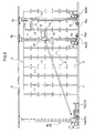
- FIG. 5 is a flowchart showing the control operation of the operating control means;
- FIG. 6 is a diagram showing the operation of the stacker crane in the simultaneous storage operation and the simultaneous retrieval operation;
- FIG. 7 is a diagram showing the operation of the stacker crane in the simultaneous storage operation and the simultaneous retrieval operation;
- FIG. 8 is a diagram showing the operation of the stacker crane in the first independent storage operation and the first independent retrieval operation; and
- FIG. 9 is a diagram showing the operation of the stacker crane in the second independent storage operation and the second independent retrieval operation.
- Embodiments of the article storage facility according to the present invention will be described based on the drawings.
- As shown in FIG. 1, this article storage facility is composed of an
article storage rack 2 provided with a plurality ofstorage units 1 arranged vertically and horizontally, and astacker crane 4 as a movable body for conveying an article B between thearticle storage rack 2 and a loading/unloadingarticle support unit 3. - In the
article storage rack 2, front andback pillars 5 are vertically arranged in a plurality of pairs at an interval in the horizontal direction, and a plurality ofplacement support units 6 extending in the horizontal direction is provided at an interval in the vertical direction to each pair of front andback pillars 5. - One pair of front and
back pillars 5 and one pair of left and rightplacement support units 6 form asingle storage unit 1, and a plurality ofstorage units 1 is provided vertically and horizontally. - Two
article storage racks 2 are provided at an interval so as to face each other in the direction in which articles move in and out, and two loading/unloadingarticle support units 3 are mounted at an interval so as to face each other at the sides of thearticle storage racks 2 and in other adjacent positions in the horizontal direction of thearticle storage rack 2. - Each of the plurality of
storage units 1 and each of the loading/unloadingarticle support units 3 in thearticle storage rack 2 is configured as an article transfer location. - A
travel rail 7 is mounted on the floor surface between the twoarticle storage racks 2 as a track that extends through the entire range of the horizontal direction of the article storage racks 2 to the loading/unloadingarticle support units 3, and aguide rail 8 that extends through the entire range of the horizontal direction of thearticle storage racks 2 to the loading/unloadingarticle support units 3 is mounted to the top side. Astacker crane 4 is provided so as to move horizontally on thetravel rail 7 while being guided by theguide rail 8. - A
ground controller 9 for managing the operation of thestacker crane 4 is provided to the end on the side of the loading/unloadingarticle support units 3 among the ends of thetravel rail 7, and theground controller 9 manages storage information such as which article is stored in whichstorage unit 1. - Two
stacker cranes 4 are provided so as to move horizontally on thesame travel rail 7. As shown in FIG. 2, each of the twostacker cranes 4 is composed of a horizontallymovable traveling truck 10 that travels along thetravel rail 7, alift platform 11 capable of lifting and lowering with respect to thetraveling truck 10, and a transfer device 12 (a fork-type transfer device, for example) as an article transfer means provided to thelift platform 11. - As a
transfer device 12, any of the various known devices, other than the fork type transfer device that has two pairs of arms are telescopically extended by a motor driven chain, may be employed. Another example of a transfer device is disclosed inUS Patent Application Publication 2005/0036858A1 , which is incorporated herein by reference. - The
stacker cranes 4 are configured so as to store an article B present in the loading/unloadingarticle support unit 3 in astorage unit 1 of thearticle storage rack 2, or to retrieve the article B stored in thestorage unit 1 of thearticle storage rack 2 to the loading/unloadingarticle support unit 3 by horizontal movement of thetraveling trucks 10, vertical movement of thelift platforms 11, and transfer of thetransfer devices 12. - As shown in FIG. 1, two
receiving platforms 13 as loading/unloadingarticle support units 3 onto which the article B is placed are arranged in the direction of horizontal movement of thestacker crane 4. The loading/unloadingarticle support units 3 used for storage and retrieval are thus configured so that twostacker cranes 4 can be positioned along the direction of horizontal movement, and an article B can be transferred to and from a receivingplatform 13 by thetransfer devices 12 provided to eachstacker crane 4. - In this embodiment, the stacker crane positioned on the side of the loading/unloading
article support units 3 among the twostacker cranes 4 is designated as thefirst stacker crane 4a, and the stacker crane positioned on the side of thearticle storage rack 2 is designated as thesecond stacker crane 4b. - Among the two
receiving platforms 13, the receiving platform positioned on the far side of thearticle storage racks 2 is designated as the first receivingplatform 13a, and the receiving platform positioned on the near side of thearticle storage racks 2 is designated as the second receivingplatform 13b. - The
first stacker crane 4a conveys an article between the first receivingplatform 13a and the article storage racks 2, and thesecond stacker crane 4b conveys an article between the second receivingplatform 13b and the article storage racks 2. - A single
vertical post 14 for guiding and supporting thelift platform 11 so as to allow thelift platform 11 to move up and down is vertically provided to thetraveling truck 10, and the position in which thisvertical post 14 is erected is substantially separated from theend portion 10a closer to the remainingsingle stacker crane 4 in the direction of horizontal movement of thestacker cranes 4. The position in which thevertical post 14 is erected may be on the opposite side from the side on which the remainingsingle stacker crane 4 is positioned in the direction of horizontal movement of thestacker cranes 4. - As shown in FIG. 2, the
lift platforms 11 of the travelingtrucks 10 each have anopposing face 11a closest to theadjacent traveling truck 10 in the direction of horizontal movement. The length L1 by which theend portion 10a closest to theadjacent traveling truck 10 protrudes from the reference surface S of the vertical post in the horizontal direction in eachtraveling truck 10 is smaller than the length L2 by which theopposing face 11a protrudes from the reference surface S in the horizontal direction. The length L1 is preferably 70% or less of the length L2. - The
lift platform 11 is suspended and supported by alift chain 15. Thelift chain 15 is suspended between aguide sprocket 17 provided to anupper frame 16 guided along theguide rail 8 and aguide sprocket 18 provided to the lower side of thevertical post 14, and is connected to atakeup drum 19 fitted to one end of thetraveling truck 10. - The
takeup drum 19 is rotatably driven forward and backward by an inverter-typeelectric lift motor 20, and thelift platform 11 is raised and lowered by the outward and inward spooling of thelift chain 15. - The
lift platform 11 is provided with alift rotary encoder 22 for detecting the vertical position of thelift platform 11 in the lift path. - This
lift rotary encoder 22 is not shown in detail in the drawing, but a sprocket for meshing with a chain laid in the vertical direction of thevertical post 14 is attached to the rotating shaft of thelift rotary encoder 22, the sprocket is rotated by the lifting of thelift platform 11, and the vertical position of thelift platform 11 is detected by detecting the lift distance of thelift platform 11 from a reference position set at the lower end portion of the lift path. - Two wheels 24 (front and back) that can travel on the
travel rail 7 are provided to thetraveling truck 10. The wheel on one end in the direction of horizontal movement among the twowheels 24 is configured as adrive wheel 24a driven by an inverter-typeelectric travel motor 25, and the wheel on the other end in the direction of horizontal movement is configured as a free-rotating drivenwheel 24b. - The inverter-type
electric travel motor 25 rotatably drives thedrive wheel 24a forward and backward, whereby thetraveling truck 10 is moved horizontally. - A
guide roller 21 capable of rotating about a horizontal axis is provided to thetraveling truck 10 in each position in which the two wheels 24 (front and back) are disposed. The roller contacts thetravel rail 7 so as to restrict upward movement, and for preventing thewheels 24 from lifting off of thetravel rail 7. - A
travel rotary encoder 23 for detecting the travel position of the travelingtruck 10 in the travel path is provided to the travelingtruck 10. - This
travel rotary encoder 23 is not shown in detail in the drawing, but a sprocket for meshing with a chain laid along thetravel rail 7 is attached to the rotating shaft of thetravel rotary encoder 23, the sprocket is rotated by the horizontal movement of the travelingtruck 10, and the travel position of the travelingtruck 10 is detected by detecting the distance which the travelingtruck 10 has moved horizontally from a reference position set at one end of thetravel rail 7. - As shown in FIG. 3, the two
stacker cranes 4 are configured so that the providedtransfer devices 12 can be positioned in an overlapped state in the vertical direction. Each of the twostacker cranes 4 is also capable of positioning the providedtransfer devices 12 in an overlapped state in the vertical direction by moving closer to theother stacker crane 4 adjacent in the direction of horizontal movement. It is preferable to have a control means that control thestacker cranes 4 and the transfer devices to have the overlap state (or overlap mode) only when there is a greater load on the storage facility e.g. when the number of articles to be carried in or out of the facility exceeds a predetermined number or when there is a predetermined number of articles that need to be processed urgently, so that when the load on the facility is light, the overlap mode is not used. Only onestacker crane 4 may be used when there is relatively small number of articles to be processed. - Positioning the
transfer devices 12 provided thereto in an overlapped state in the vertical direction in this manner allows the twostacker cranes 4 to transfer articles B simultaneously with respect to twostorage units 1 having the same position in the horizontal direction of the rack and different positions in the vertical direction of the rack among the plurality ofstorage units 1 in thearticle storage rack 2. - When the two
stacker cranes 4 are in proximity to each other so as to be adjacent to each other, the position of thevertical post 14 in the horizontal direction in the travelingtruck 10 is adjusted so that the travelingtrucks 10 do not come in contact with each other, while thetransfer devices 12 overlap each other in the vertical direction. The width of theupper frame 16 in the horizontal direction is also adjusted when the twostacker cranes 4 are in proximity to each other so that theupper frames 16 do not come in contact with each other, while thetransfer devices 12 overlap each other in the horizontal direction. - As shown in FIG. 4, a
crane control device 26 for controlling the operation of thestacker crane 4 is provided to each of the twostacker cranes 4. In FIG. 4, thecrane control device 26 provided to thefirst stacker crane 4a is designated as the firstcrane control device 26A, and thecrane control device 26 provided to thesecond stacker crane 4b is designated as the secondcrane control device 26B. - The detection information of the
lift rotary encoders 22 and the detection information of thetravel rotary encoders 23 are inputted to thecrane control devices 26. - The first
crane control device 26A and the secondcrane control device 26B have the same structure. - The
crane control devices 26 are configured so that the horizontal movement of the travelingtrucks 10 and the vertical movement of thelift platforms 11 are controlled so as to move thetransfer devices 12 to rack-side article transfer positions at each of the plurality ofstorage units 1, and to convey articles with controlled transfer of thetransfer devices 12 so that thetransfer devices 12 transfer articles to and from thestorage units 1 and the loading/unloadingarticle support units 3 in the rack-side article transfer positions and the loading/unloading-side article transfer position. - Specifically, the rack-side article transfer position and the loading/unloading-side article transfer position are positions measured from a lift target stopping position and a travel target stopping position. A loading/unloading-side article transfer position is determined for each of the two receiving
platforms 13, and a lift target stopping position and a travel target stopping position are set for each of the two receivingplatforms 13. An rack-side article transfer position is determined for each of the plurality ofstorage units 1, and a lift target stopping position and a travel target stopping position are set for each of the plurality ofstorage units 1. - The
crane control devices 26 are composed of atravel control unit 26a for controlling the horizontal movement of the travelingtruck 10 so as to cause the travelingtruck 10 to travel to a prescribed travel target stopping position based on the detection information of thetravel rotary encoder 23, alift control unit 26b for controlling the lift actuation of thelift platform 11 so as to cause thelift platform 11 to rise to a prescribed lift target stopping position based on the detection information of thelift rotary encoder 22, and atransfer control unit 26c for controlling the transfer of thetransfer device 12 so that articles are transferred to and from thestorage units 1 and the receivingplatforms 13. - In the travel control performed in the
travel control unit 26a, theelectric travel motor 25 is started to initiate horizontal movement of the travelingtruck 10, and when the travel position of the travelingtruck 10 detected by thetravel rotary encoder 23 reaches the prescribed travel target stopping position, theelectric travel motor 25 is stopped, a brake is applied, and operation of theelectric travel motor 25 is controlled so that the travelingtruck 10 is stopped in the travel target stopping position. - In the lift control procedure of the
lift control unit 26b, theelectric lift motor 20 is started to initiate vertical movement of thelift platform 11, and when the vertical position of thelift platform 11 detected by thelift rotary encoder 22 reaches the prescribed lift target stopping position, theelectric lift motor 20 is stopped, a brake is applied, and operation of theelectric lift motor 20 is controlled so that thelift platform 11 is stopped in the lift target stopping position. - In the transfer control procedure of the
transfer control unit 26c, the fork-type transfer device 12 is started, and transfer of thetransfer device 12 is controlled so that the fork is extended, the article B is loaded or unloaded, and the fork is then retracted. - Various types of information can be transmitted between the
crane control device 26 and theground controller 9, and theground controller 9 issues various types of instructions to the twocrane control devices 26, which include the firstcrane control device 26A and the secondcrane control device 26B. - The
crane control devices 26 are configured so that travel control is performed by thetravel control unit 26a, lift control is performed by thelift control unit 26b, and transfer control is performed by thetransfer control unit 26c on the basis of instructions from theground controller 9, whereby articles are conveyed. - A control means H for controlling the operation of the plurality of
stacker cranes 4 is thus composed of theground controller 9 and twocrane control devices 26. - The control means H is configured so as to select both of the two
stacker cranes 4 or one of the twostacker cranes 4 as an article-conveyingstacker crane 4, and to perform an article conveyance operation based on article conveyance command information. - When the control means H selects one of the two
stacker cranes 4 as the article-conveyingstacker crane 4, the control means H performs a selection operation for selecting the article-conveyingstacker crane 4 among the twostacker cranes 4, and performs an article conveyance operation for causing thestacker crane 4 selected in the selection operation to convey the article. - In the selection operation, the
stacker crane 4 that will convey the article is selected on the basis of whether thestacker crane 4 is currently conveying an article, what the current positions of the twostacker cranes 4 are, and other selection conditions. For example, when both of the twostacker cranes 4 are in the loading/unloading-side article transfer position, thesecond stacker crane 4b is selected as thestacker crane 4 that will convey the article. - The control means H thus selectively executes a simultaneous storage operation, a first independent storage operation, a second independent storage operation, a simultaneous retrieval operation, a first independent retrieval operation, or a second independent retrieval operation based on article conveyance command information and selection conditions.
- The simultaneous storage operation and the simultaneous retrieval operation are article conveyance operations in which both of the two
stacker cranes 4 are selected as stacker cranes that will convey an article. - The first independent storage operation and the first independent retrieval operation are article conveyance operations in which the
first stacker crane 4a among the twostacker cranes 4 is selected as the stacker crane that will convey an article. - The second independent storage operation and the second independent retrieval operation are article conveyance operations in which the
second stacker crane 4b among the twostacker cranes 4 is selected as the stacker crane that will convey an article. - The flowchart in FIG. 5 will be used to describe which operation the control means H executes among the plurality of operations based on the article conveyance command information and the selection conditions.
- The control means H selects and executes the simultaneous storage operation when the article conveyance command information requires storage of a plurality of articles B (steps 1 and 2).
- The control means H performs the operation for selecting either the first independent storage operation or the second independent storage operation based on the selection conditions when the article conveyance command information requires storage of a single article B, and executes the operation selected in the selection operation (
steps 3 through 5). - The control means H selects and executes the simultaneous retrieval operation when the article conveyance command information requires retrieval of a plurality of articles B (steps 6 and 7).
- The control means H performs the selection operation for selecting either the first independent retrieval operation or the second independent retrieval operation based on the selection conditions when the article conveyance command information requires retrieval of a single article B, and executes the sequence selected in the selection operation (
steps 8 through 10). - The operation of the two
stacker cranes 4 in the simultaneous storage operation, the first independent storage operation, the second independent storage operation, the simultaneous retrieval operation, the first independent retrieval operation, and the second independent retrieval operation will be described hereinafter based on FIGS. 6 through 9. - FIGS. 6 through 9 are side views in which a portion of the article storage facility is omitted, wherein the loading/unloading
article support unit 3 is positioned at the left end, and thearticle storage rack 2 is positioned to the right of the loading/unloadingarticle support unit 3. - The operation performed in the simultaneous storage operation will first be described based on FIGS. 6 and 7. In this simultaneous storage operation, both of the two
stacker cranes 4 that include thefirst stacker crane 4a and thesecond stacker crane 4b convey and store articles. - The
ground controller 9 issues a storage instruction to both the firstcrane control device 26A in thefirst stacker crane 4a and the secondcrane control device 26B in thesecond stacker crane 4b. - The storage instruction issued to the first
crane control device 26A is an instruction for causing an article B placed on thefirst receiving platform 13a to be stored in astorage unit 1, and indicates the lift target stopping position and travel target stopping position for the loading/unloading-side article transfer position at thefirst receiving platform 13a, and the rack-side article transfer position at thestorage unit 1 in which the article B is to be stored. - The storage instruction issued to the second
crane control device 26B is an instruction for causing an article B placed on thesecond receiving platform 13b to be stored in astorage unit 1, and indicates the lift target stopping position and travel target stopping position for the loading/unloading-side article transfer position at thesecond receiving platform 13b, and the rack-side article transfer position at thestorage unit 1 in which the article B is to be stored. - Concerning the
storage units 1 in which the articles B are to be stored, a plurality ofstorage units 1 having different positions in the horizontal direction of the rack is sometimes designated as thestorage units 1 that are the transfer targets in which the articles B are to be stored, as shown in FIG. 6. A plurality ofstorage units 1 having the same position in the horizontal direction of the rack and different positions in the vertical direction of the rack is also sometimes designated as thestorage units 1 that are the transfer targets in which the articles B are to be stored, as shown in FIG. 7. - Described below with reference to Fig. 6 is a case in which a plurality of
storage units 1 having different positions in the horizontal direction of the rack is designated as the transfertarget storage units 1. - Instructions issued by the
ground controller 9 are such that the storage instruction for the firstcrane control device 26A ensures that thestorage unit 1 designated to store the article B is closer to the loading/unloadingarticle support unit 3 in the horizontal direction of the rack than the storage unit designated by the storage instruction for the secondcrane control device 26B. - When the storage instruction is received by the first
crane control device 26A, thefirst stacker crane 4a first receives the article B placed on thefirst receiving platform 13a as indicated by the solid-line arrow in FIG. 6, and travel control by thetravel control unit 26a, lift control by thelift control unit 26b, and transfer control by thetransfer control unit 26c are then performed so that thefirst stacker crane 4a stores the received article B in theappropriate storage unit 1. - When the storage instruction is received by the second
crane control device 26B, thesecond stacker crane 4b first receives the article B placed on thesecond receiving platform 13b as indicated by the solid-line arrow in FIG. 6, and travel control by thetravel control unit 26a, lift control by thelift control unit 26b, and transfer control by thetransfer control unit 26c are then performed so that thesecond stacker crane 4b stores the received article B in theappropriate storage unit 1. - Described below with reference to FIG. 7 is a case in which a plurality of
storage units 1 having the same position in the horizontal direction of the rack and different positions in the vertical direction of the rack is designated as the transfertarget storage units 1. - The control means H executes a simultaneous transfer operation for controlling the horizontal movement of two
stacker cranes 4, the rising and lowering of twotransfer devices 12, and the transfer of twotransfer devices 12 in order to position thetransfer devices 12 provided to twostacker cranes 4 in the rack-side article transfer positions that correspond to the transfertarget storage units 1 in an overlapped state in the vertical direction, and use thetransfer devices 12 to transfer an article B between the transfertarget storage units 1 when the article is transferred between a plurality of transfertarget storage units 1. - The control means H is also configured so that in the simultaneous transfer operation, the
transfer device 12 provided to one of thestacker cranes 4 among the twostacker cranes 4 adjacent to each other in the direction of horizontal movement is positioned in the rack-side article transfer position, thestacker crane 4 is moved horizontally, and thetransfer device 12 is raised or lowered. Theother stacker crane 4 is also moved horizontally so that itstransfer device 12 remain within a non-interference range Q in which there is no interference in the vertical direction with thetransfer device 12 provided to theother stacker crane 4, thisstacker crane 4 is moved horizontally, and thetransfer device 12 is raised or lowered. - Furthermore, the
ground controller 9 issues a storage instruction for simultaneous transfer to the secondcrane control device 26B so that the transfertarget storage unit 1 has the same position in the horizontal direction of the rack and a different position in the vertical direction of the rack, and issues a storage instruction for simultaneous transfer to the firstcrane control device 26A. - When the storage instruction for simultaneous transfer is received by the second
crane control device 26B, thesecond stacker crane 4b first receives the article B placed on thesecond receiving platform 13b as indicated by the solid-line arrow in FIG. 7, and travel control by thetravel control unit 26a, lift control by thelift control unit 26b, and transfer control by thetransfer control unit 26c are then performed so that thesecond stacker crane 4b stores the received article B in theappropriate storage unit 1. - When the storage instruction for simultaneous transfer is received by the first
crane control device 26A, travel control by thetravel control unit 26a, lift control by thelift control unit 26b, and transfer control by thetransfer control unit 26c are first performed so that thefirst stacker crane 4a receives the article B placed on thefirst receiving platform 13a. - The
first stacker crane 4a then stores the received article B in theappropriate storage unit 1. Travel control by thetravel control unit 26a and lift control by thelift control unit 26b are performed at this time in the firstcrane control device 26A so that thetransfer device 12 of thesecond stacker crane 4b and thetransfer device 12 of thefirst stacker crane 4a overlap each other in the vertical direction. - In the first
crane control device 26A, travel control by thetravel control unit 26a and lift control by thelift control unit 26b are performed so that thetransfer device 12 of thefirst stacker crane 4a is caused to move closer to the rack-side article transfer position at thestorage unit 1 in which the article B is to be stored, and thetransfer device 12 of thefirst stacker crane 4a is positioned within the non-interference range Q in which there is no interference in the vertical direction with thetransfer device 12 of thesecond stacker crane 4b when thetransfer device 12 of thesecond stacker crane 4b and thetransfer device 12 of thefirst stacker crane 4a are superposed on each other in the vertical direction. - Measures are thus taken to ensure that the
transfer device 12 of thefirst stacker crane 4a and the transfer device of thesecond stacker crane 4b do not come in contact with each other. Any non-interference range Q can be adopted as long as there is no interference in the vertical direction with thetransfer device 12 of thesecond stacker crane 4b. For example, a range may also be set that has a width equal to a set width in the vertical direction of the placement position from the placement position of thestorage unit 1 in which thefirst stacker crane 4 stores the article B. - The first
crane control device 26A then causes thetransfer device 12 of thefirst stacker crane 4a to be positioned in the rack-side article transfer position at thestorage unit 1 in which the article B is to be stored, whereupon transfer control by thetransfer control unit 26c is performed so that thefirst stacker crane 4a stores the received article B in theappropriate storage unit 1. - The first independent storage operation will next be described based on FIG. 8. This first independent storage operation allows an article to be stored by being conveyed using the
first stacker crane 4a among the twostacker cranes 4. - The
ground controller 9 issues a storage instruction to the firstcrane control device 26A, and issues a standby instruction or an ejection instruction to the secondcrane control device 26B. - The standby instruction is an instruction for causing the
second stacker crane 4b to stand by in position. The ejection instruction is an instruction for moving thesecond stacker crane 4b outside the range in which thefirst stacker crane 4a moves in order to convey an article, and indicates the travel target stopping position of astorage unit 1 outside this range. - In the first
crane control device 26A, travel control by thetravel control unit 26a, lift control by thelift control unit 26b, and transfer control by thetransfer control unit 26c are performed so that thefirst stacker crane 4a first receives the article B placed on thefirst receiving platform 13a, and then thefirst stacker crane 4a stores the received article B in theappropriate storage unit 1, as indicated by the solid-line arrow in FIG. 8. - When a standby instruction is received by the second
crane control device 26B, thesecond stacker crane 4b is caused to stand by in position as indicated by the solid line in the drawing, without travel control by thetravel control unit 26a, lift control by thelift control unit 26b, or transfer control by thetransfer control unit 26c being performed. - When an ejection instruction is received by the second
crane control device 26B, travel control by thetravel control unit 26a is performed so that the travelingtruck 10 is positioned in the prescribed travel target stopping position, as indicated by the solid line in the drawing. - The second independent storage operation will next be described based on FIG. 9. This second independent storage operation allows an article to be stored by being conveyed using the
second stacker crane 4b among the twostacker cranes 4. - The
ground controller 9 issues an ejection instruction for HP to the firstcrane control device 26A, and issues a storage instruction to the secondcrane control device 26B in thesecond stacker crane 4b. - In this ejection instruction for HP, the travel target stopping position is indicated for the loading/unloading-side article transfer position at the
first receiving platform 13a. - In the first
crane control device 26A, travel control by thetravel control unit 26a is performed so that the travelingtruck 10 is positioned in the travel target stopping position as the loading/unloading-side article transfer position at thefirst receiving platform 13a. - In the second
crane control device 26B, travel control by thetravel control unit 26a, lift control by thelift control unit 26b, and transfer control by thetransfer control unit 26c are performed so that thesecond stacker crane 4b first receives the article B placed on thesecond receiving platform 13b, and then thesecond stacker crane 4b stores the received article B in theappropriate storage unit 1, as indicated by the solid-line arrow in FIG. 9. - The simultaneous retrieval operation will next be described based on the dashed-line arrows and the like in FIGS. 6 and 7. In the reverse of the simultaneous storage operation, the simultaneous retrieval operation retrieves an article by causing the article to be conveyed by the two
stacker cranes 4 that include thefirst stacker crane 4a and thesecond stacker crane 4b. - The
ground controller 9 issues a retrieval instruction to both the firstcrane control device 26A and the secondcrane control device 26B. - The retrieval instruction for the first
crane control device 26A is an instruction for bringing the article B stored in thestorage unit 1 to thefirst receiving platform 13a, and indicates the lift target stopping position and travel target stopping position as the rack-side article transfer position at thestorage unit 1 from which the article B is to be retrieved, and the loading/unloading-side article transfer position at thefirst receiving platform 13a. - The retrieval instruction for the second
crane control device 26B is an instruction for bringing the article B stored in thestorage unit 1 to thesecond receiving platform 13b, and indicates the lift target stopping position and travel target stopping position as the rack-side article transfer position at thestorage unit 1 from which the article B is to be retrieved, and as the loading/unloading-side article transfer position at thesecond receiving platform 13b. - Concerning the
storage units 1 from which the articles B are to be retrieved, a plurality ofstorage units 1 having different positions in the horizontal direction of the rack is sometimes designated as thestorage units 1 that are the transfer targets from which articles B are to be retrieved and transferred, as shown in FIG. 6. A plurality ofstorage units 1 having the same position in the horizontal direction of the rack and different positions in the vertical direction of the rack is also sometimes designated as thestorage units 1 that are the transfer targets from which articles B are to be retrieved and transferred, as shown in FIG. 7. - Described below with reference to FIG. 6 is a case in which a plurality of
storage units 1 having different positions in the horizontal direction of the rack is designated as the transfertarget storage units 1. - Instructions issued by the
ground controller 9 are such that the retrieval instruction for the firstcrane control device 26A ensures that thestorage unit 1 from which the article B is to be retrieved is closer to the loading/unloadingarticle support unit 3 in the horizontal direction of the rack than storage the unit designated by the retrieval instruction for the secondcrane control device 26B. - When the retrieval instruction is received by the first
crane control device 26A, thefirst stacker crane 4a first retrieves the article B stored in the transfertarget storage unit 1 as indicated by the dashed-line arrow in FIG. 6, and travel control by thetravel control unit 26a, lift control by thelift control unit 26b, and transfer control by thetransfer control unit 26c are then performed so that thefirst stacker crane 4a places the retrieved article B on thefirst receiving platform 13a. - When the retrieval instruction is received by the second
crane control device 26B, thesecond stacker crane 4b first retrieves the article B stored in the transfertarget storage unit 1 as indicated by the dashed-line arrow in FIG. 6, and travel control by thetravel control unit 26a, lift control by thelift control unit 26b, and transfer control by thetransfer control unit 26c are then performed so that thesecond stacker crane 4b places the retrieved article B on thesecond receiving platform 13b. - Described below with reference to FIG. 7 is a case in which a plurality of
storage units 1 having the same position in the horizontal direction of the rack and different positions in the vertical direction of the rack is designated as the transfertarget storage units 1. - The control means H is configured so as to execute the simultaneous transfer operation in the same manner as the simultaneous storage operation described above when articles B are transferred among a plurality of transfer
target storage units 1 in the simultaneous retrieval operation. - Furthermore, the
ground controller 9 issues a retrieval instruction for simultaneous transfer of articles to the secondcrane control device 26B so that the transfertarget storage units 1 have the same position in the horizontal direction of the rack and a different position in the vertical direction of the rack, and issues a retrieval instruction for simultaneous transfer of the articles to the firstcrane control device 26A. - When the retrieval instruction for simultaneous transfer is received by the second
crane control device 26B, thesecond stacker crane 4b first retrieves an article B stored in the corresponding transfertarget storage unit 1 as indicated by the dashed-line arrow in FIG. 7, and travel control by thetravel control unit 26a, lift control by thelift control unit 26b, and transfer control by thetransfer control unit 26c are then performed so that thesecond stacker crane 4b transfers the retrieved article B to thesecond receiving platform 13b. - When the retrieval instruction for simultaneous transfer is received by the first
crane control device 26A, thefirst stacker crane 4a first retrieves an article B stored in the corresponding transfertarget storage unit 1. At this time, travel control by thetravel control unit 26a and lift control by thelift control unit 26b are performed so that thetransfer device 12 of thesecond stacker crane 4b and thetransfer device 12 of thefirst stacker crane 4a overlap each other in the vertical direction. - The first
crane control device 26A causes thetransfer device 12 of thesecond stacker crane 4b and thetransfer device 12 of thefirst stacker crane 4a to be superposed on each other in the vertical direction, whereupon travel control by thetravel control unit 26a and lift control by thelift control unit 26b are performed so that thetransfer device 12 of thefirst stacker crane 4a moves closer to the rack-side article transfer position at thestorage unit 1 in which the article B is to be stored, and thetransfer device 12 of thefirst stacker crane 4a is positioned within the non-interference range Q in which there is no interference in the vertical direction with thetransfer device 12 of thesecond stacker crane 4b. When thetransfer device 12 of thefirst stacker crane 4a is subsequently positioned in the rack-side article transfer position at thestorage unit 1 in which the article B is to be stored, transfer control by thetransfer control unit 26c is performed so that thefirst stacker crane 4a stores the received in theappropriate storage unit 1. - In the first
crane control device 26A, travel control by thetravel control unit 26a, lift control by thelift control unit 26b, and transfer control by thetransfer control unit 26c are then performed so that thefirst stacker crane 4a places the retrieved article B on thefirst receiving platform 13a. - The first independent retrieval operation will next be described based on the dashed-line arrow and the like in FIG. 8. In the reverse of the first independent storage operation, the first independent retrieval operation retrieves an article by causing the article to be conveyed by the
first stacker crane 4a. - The
ground controller 9 issues a retrieval instruction to the firstcrane control device 26A, and issues a standby instruction or an ejection instruction to the secondcrane control device 26B. - In the first
crane control device 26A, travel control by thetravel control unit 26a, lift control by thelift control unit 26b, and transfer control by thetransfer control unit 26c are performed so that thefirst stacker crane 4a first retrieves the article B stored in thestorage unit 1, and then thefirst stacker crane 4a places the retrieved article B on thefirst receiving platform 13a, as indicated by the dashed-line arrow in FIG. 8. - When a standby instruction is received by the second
crane control device 26B, thesecond stacker crane 4b is caused to stand by in position without travel control by thetravel control unit 26a, lift control by thelift control unit 26b, or transfer control by thetransfer control unit 26c being performed. When an ejection instruction is received by the secondcrane control device 26B, travel control by thetravel control unit 26a is performed so that the travelingtruck 10 is positioned in the prescribed travel target stopping position. - The second independent retrieval operation will next be described. In this operation, which is the reverse of the second independent storage operation, an article is retrieved by being conveyed using the
second stacker crane 4b. - The
ground controller 9 issues an ejection instruction for HP to the firstcrane control device 26A, and issues a retrieval instruction to the secondcrane control device 26B. - In the first
crane control device 26A, travel control by thetravel control unit 26a is performed so that the travelingtruck 10 is positioned in the travel target stopping position for the loading/unloading-side article transfer position at thefirst receiving platform 13a. - In the second
crane control device 26B, travel control by thetravel control unit 26a, lift control by thelift control unit 26b, and transfer control by thetransfer control unit 26c are performed so that thesecond stacker crane 4b first retrieves the article B stored in thestorage unit 1, and then thesecond stacker crane 4b places the retrieved on thefirst receiving platform 13a, as indicated by the dashed-line arrow in FIG. 9. -
- (1) In the embodiment described above, two
stacker cranes 4 are brought into proximity with each other in the direction of horizontal movement, whereby the providedtransfer devices 12 overlap each other in the vertical direction. It is, however, possible to appropriately modify the manner in which thetransfer devices 12 of the twostacker cranes 4 are overlapped with each other in the vertical direction.
For example, thetransfer devices 12 of the twostacker cranes 4 may be provided so as to be capable of moving not only vertically, but also horizontally along the direction of horizontal movement of thestacker cranes 4. A configuration may also be adopted in which thetransfer devices 12 provided to the twostacker cranes 4 overlap each other in the vertical direction by being moved horizontally after thestacker cranes 4 are brought into proximity with each other in the direction of horizontal movement. - (2) In the embodiment described above, a
travel rotary encoder 23 or alift rotary encoder 22 is provided in order to detect the travel position of the travelingtruck 10 on the travel path, or the vertical position of thelift platform 11 on the lift path. However, it is also possible to detect the travel position of the travelingtruck 10 on the travel path or the vertical position of thelift platform 11 on the lift path by using a laser rangefinder, for example, and various types of sensors may be implemented. - (3) In the embodiment described above; an example was described in which two
stacker cranes 4 are provided, but a configuration may also be adopted in which three ormore stacker cranes 4 are provided. - (4) In the simultaneous transfer operation according to the embodiment described above, the
second stacker crane 4b is moved horizontally, and thetransfer device 12 is raised or lowered so that thetransfer device 12 of thesecond stacker crane 4b is positioned in a rack-side article transfer position, and thefirst stacker crane 4a is also moved horizontally and thetransfer device 12 is raised or lowered so that thetransfer device 12 is positioned in a rack-side article transfer position, with thetransfer device 12 of thefirst stacker crane 4a positioned within the non-interference range Q. However, it is possible to appropriately change which of the twostacker cranes 4 is moved horizontally while thetransfer device 12 is kept within the non-interference range Q.
Claims (6)
- An article storage facility comprising:an article storage rack (2) having a plurality of storage units (1) arranged in horizontal rows and vertical columns;a track (7) extending in a vicinity of said article storage rack (2);a plurality of article-conveying movable bodies (4) capable of moving horizontally on said track (7) in order to convey an article (B) between said article storage rack (2) and a loading/unloading article support unit (3);article transfer means (12), provided to each of said movable bodies (4) and being capable of vertical movement, for transferring said article (B) between the movable body and a storage unit (1) or the article support unit (3); andcontrol means (H) for controlling the movements of said movable bodies (4);characterized in thatthe dimensions of said movable bodies (4) are determined so as to enable two of said movable bodies (4) adjacent each other in the horizontal direction to be positioned such that the two article transfer means (12), provided to the two adjacent movable bodies (4), overlap in the vertical direction.
- The article storage facility according to claim 1, characterized in that
said control means (H) controls the horizontal movement of said movable bodies (4) and the vertical movement of said article transfer means (12) in order to cause said article transfer means (12) to move to rack-side article transfer positions at each of said plurality of storage units (1), and to the loading/unloading-side article transfer position at said loading/unloading article support unit (3), and controls the transfer of the article transfer device so that said article transfer means (12) transfers articles (B) to and from said storage units (1) at said rack-side article transfer positions, and to and from said loading/unloading article support unit (3) at said loading/unloading-side article transfer position; and
said control means (H) positions said article transfer means (12) provided to two of said movable bodies (4) in the rack-side article transfer position at the storage unit (1) that is the transfer target, and executes a simultaneous transfer operation for controlling the horizontal movement of said plurality of movable bodies (4), the vertical movement of said plurality of article transfer means (12), and the transfer of said plurality of article transfer means (12) so that an article (B) is transferred to the storage unit (1) to which the article (B) is to be transferred by said article transfer means (12) when a plurality of articles (B) is transferred, with the transfer targets comprising a plurality of storage units (1) having the same position in the horizontal direction of the rack and different positions in the vertical direction of the rack among the plurality of storage units (1) in said article storage rack (2). - The article storage facility according to claim 1 or 2, characterized in that
each of said two movable bodies (4) adjacent to each other in the direction of horizontal movement is provided with said article transfer means (12) such that the article transfer means (12) can be raised and lowered along a single vertical post (14) vertically arranged at a position substantially spaced apart from a first end portion that is closer to an adjacent movable body in the direction of horizontal movement. - The article storage facility according to claim 2, characterized in that
said control means (H) causes a first moving body of said two movable bodies (4) to move horizontally and said article transfer means (12) to move vertically in order to position said article transfer means (12), which is provided to one of the two movable bodies (4) that are adjacent to each other in the direction of horizontal movement, in the article transfer position on the side of said rack in said simultaneous transfer operation, and causes a second moving body of said movable bodies (4) to move horizontally and said article transfer means (12) to move vertically in order to position said article transfer means (12) of the second moving body in the article transfer position on the side of said rack so as to cause said article transfer means (12) provided to the second movable body to remain within an non-interference range in which there is no interference in the vertical direction with said article transfer means (12) provided to the first movable body. - The article storage facility according to claim 3, characterized in that
said article transfer means (12) of each of said movable bodies (4) has an opposing face that is closest to the vertical post (14) provided to a movable body that is adjacent in the direction of horizontal movement; and
the length (L1) by which said first end portion, of each of said movable bodies (4) that is closer than the other end to each of said adjacent movable bodies (4), protrudes in the horizontal direction with respect to a reference surface of said vertical post (14) is less than the length (L2) by which said opposing face protrudes in the horizontal direction from said reference surface of said vertical post (14). - The article storage facility according to claim 3, further comprising:a guide rail (8) spaced apart in the vertical direction from said track (7);said vertical post (14) of each of said movable bodies (4) has an upper frame (16) at the top portion thereof and guided by said guide rail (8); and whereinthe width of said upper frame (16) in the horizontal direction is determined such that said upper frames (16) of said two movable bodies (4) do not come in contact with each other when said article transfer means (12) of said two movable bodies (4) overlap each other in the vertical direction.
Applications Claiming Priority (1)
| Application Number | Priority Date | Filing Date | Title |
|---|---|---|---|
| JP2005196344A JP4666213B2 (en) | 2005-07-05 | 2005-07-05 | Goods storage equipment |
Publications (2)
| Publication Number | Publication Date |
|---|---|
| EP1741644A1 EP1741644A1 (en) | 2007-01-10 |
| EP1741644B1 true EP1741644B1 (en) | 2007-10-17 |
Family
ID=36930405
Family Applications (1)
| Application Number | Title | Priority Date | Filing Date |
|---|---|---|---|
| EP06013757A Active EP1741644B1 (en) | 2005-07-05 | 2006-07-03 | Article storage facility |
Country Status (9)
| Country | Link |
|---|---|
| US (1) | US7575407B2 (en) |
| EP (1) | EP1741644B1 (en) |
| JP (1) | JP4666213B2 (en) |
| KR (1) | KR101259966B1 (en) |
| CN (1) | CN1891582B (en) |
| AT (1) | ATE375943T1 (en) |
| DE (1) | DE602006000166T2 (en) |
| ES (1) | ES2296250T3 (en) |
| TW (1) | TWI373441B (en) |
Families Citing this family (48)
| Publication number | Priority date | Publication date | Assignee | Title |
|---|---|---|---|---|
| US20090152289A1 (en) * | 2005-09-29 | 2009-06-18 | Jiacong Chen | Flat Item Depositing and Outputting Apparatus |
| JP4583394B2 (en) * | 2006-03-03 | 2010-11-17 | 韓国ガス公社 | Scaffolding device and heat insulation system installation method using the same |
| US8260454B2 (en) | 2007-02-16 | 2012-09-04 | Boomerang Systems, Inc. | Automated storage system |
| JP4378659B2 (en) * | 2007-06-28 | 2009-12-09 | 株式会社ダイフク | Goods storage facilities and goods storage facilities for clean rooms |
| JP5278724B2 (en) | 2007-07-26 | 2013-09-04 | 株式会社ダイフク | Goods storage equipment |
| WO2009016696A1 (en) * | 2007-07-27 | 2009-02-05 | Fujitsu Limited | Library device |
| WO2009016697A1 (en) | 2007-07-27 | 2009-02-05 | Fujitsu Limited | Library device |
| DE102007040863B4 (en) | 2007-08-29 | 2010-07-29 | Hänel & Co. | Storage rack with transport device |
| EP2332859B1 (en) * | 2008-09-05 | 2016-01-06 | Daifuku Co., Ltd. | Article storage facility and method of operating the same |
| US8397645B2 (en) * | 2008-09-08 | 2013-03-19 | Swisslog Evomatic Gmbh | Storage and retrieval machine |
| US8146718B2 (en) * | 2008-09-30 | 2012-04-03 | Agilent Technologies, Inc. | Automatic system brake |
| EP2380827B1 (en) * | 2009-01-08 | 2013-11-27 | Daifuku Co., Ltd. | Article receiving facility |
| DE102010010433A1 (en) * | 2010-02-26 | 2011-09-01 | SSI Schäfer Noell GmbH Lager- und Systemtechnik | Shelving system and method of operating the same |
| JP5429570B2 (en) * | 2010-03-08 | 2014-02-26 | 株式会社ダイフク | Goods transport equipment |
| JP5318005B2 (en) * | 2010-03-10 | 2013-10-16 | 株式会社Sokudo | Substrate processing apparatus, stocker apparatus, and substrate container transport method |
| US9505555B2 (en) * | 2011-07-01 | 2016-11-29 | Mi-Jack Products, Inc. | Chassis stacker |
| US9574363B1 (en) | 2011-07-01 | 2017-02-21 | Mi-Jack Products, Inc. | System and method of handling chassis |
| CN102285513A (en) * | 2011-08-12 | 2011-12-21 | 北京达特烟草成套设备技术开发有限责任公司 | Cluster tobacco warehousing system |
| JP5800193B2 (en) * | 2011-11-07 | 2015-10-28 | 株式会社ダイフク | Goods storage equipment |
| JP5713203B2 (en) * | 2012-03-27 | 2015-05-07 | 株式会社ダイフク | Goods storage equipment |
| CN103253478B (en) * | 2013-04-27 | 2015-08-05 | 苏州市艾信物联网技术有限公司 | Rectangular robot and medical disposable material thesaurus |
| US9764898B2 (en) | 2013-06-28 | 2017-09-19 | Murata Machinery, Ltd. | Automated warehouse and operation method for same |
| CN103434784B (en) * | 2013-08-28 | 2015-07-22 | 苏州卫捷医药科技有限公司 | Medical multifunctional storage and taking warehouse |
| JP2016210518A (en) * | 2013-10-23 | 2016-12-15 | 村田機械株式会社 | Automated warehouse and operation method of the same |
| KR101608746B1 (en) | 2014-04-29 | 2016-04-05 | 주식회사신흥기계 | A driving device for traveller of a stacker crane |
| WO2015170660A1 (en) * | 2014-05-07 | 2015-11-12 | 伊東電機株式会社 | Lifting apparatus |
| JP6201977B2 (en) * | 2014-12-19 | 2017-09-27 | 村田機械株式会社 | Automatic warehouse and its operation method |
| GB201509921D0 (en) | 2015-06-08 | 2015-07-22 | Ocado Innovation Ltd | Object storage, handling and retrieving system and method |
| DK179085B1 (en) * | 2016-03-21 | 2017-10-16 | Apm Terminals Man Bv | Container handling equipment controller arrangement |
| DK179592B1 (en) | 2016-03-21 | 2019-02-22 | Apm Terminals Management Bv | Communication device for a container handling equipment device and communication method |
| CN109415163B (en) * | 2016-06-27 | 2020-12-29 | 村田机械株式会社 | Conveying system |
| CN109415164A (en) * | 2016-06-28 | 2019-03-01 | 伯曼集团股份公司 | Storage and extraction system |
| CN106865092A (en) * | 2017-04-24 | 2017-06-20 | 深圳市鸿鹭工业设备有限公司 | Piler |
| CN108466790A (en) * | 2018-04-25 | 2018-08-31 | 合肥哈工众志自动化科技有限公司 | A kind of unmanned supermarket system and sale, replenishing method |
| CN108840006B (en) * | 2018-05-14 | 2020-02-14 | 青岛海盈智高新技术有限公司 | Convenient medicine dispensing device for western medicine pharmacy |
| GB2590246A (en) | 2018-07-12 | 2021-06-23 | Walmart Apollo Llc | System and method for product recognition and assignment at an automated storage and retrieval device |
| WO2020014608A1 (en) | 2018-07-12 | 2020-01-16 | Walmart Apollo, Llc | Automated storage retrieval system connection and communication protocol |
| US20200239229A1 (en) * | 2018-08-02 | 2020-07-30 | Walmart Apollo, Llc | Systems and Methods for Object Storage and Retrieval |
| WO2019154433A2 (en) * | 2018-11-05 | 2019-08-15 | 上海快仓智能科技有限公司 | Item transportation robot and control method therefor |
| CN111345635B (en) * | 2018-12-20 | 2023-05-02 | 北京京东乾石科技有限公司 | Exercise device |
| CN109665182B (en) * | 2019-02-15 | 2020-03-10 | 淄博职业学院 | Business enterprise management device |
| CN111591641B (en) * | 2019-02-21 | 2022-04-22 | 江苏华章物流科技股份有限公司 | Automatic three-dimensional container system and storing and taking method thereof |
| CN110550366A (en) * | 2019-09-05 | 2019-12-10 | 珠海格力智能装备有限公司 | Warehousing method and warehouse system based on double-station stacker |
| CN110980091B (en) * | 2019-12-25 | 2021-08-27 | 深圳市丰巢科技有限公司 | Storage system, method and storage medium |
| CN112777216A (en) * | 2021-01-15 | 2021-05-11 | 国网新疆电力有限公司营销服务中心(资金集约中心、计量中心) | Full-automatic electric energy metering appliance dense cabinet with built-in truss |
| US11724878B2 (en) | 2021-07-06 | 2023-08-15 | Intelligrated Headquarters, Llc | Modular vertical lift system |
| CN113697062A (en) * | 2021-09-06 | 2021-11-26 | 上海外高桥造船海洋工程有限公司 | Material conveying device for upper building subsection construction |
| CN113830485B (en) * | 2021-09-25 | 2023-01-10 | 浙江立镖机器人有限公司 | Goods loading and unloading equipment fixed on goods shelf |
Family Cites Families (14)
| Publication number | Priority date | Publication date | Assignee | Title |
|---|---|---|---|---|
| GB2257966B (en) * | 1991-04-26 | 1994-08-31 | Daifuku Kk | Rack arrangement |
| JP2859219B2 (en) * | 1996-09-13 | 1999-02-17 | 米沢日本電気株式会社 | Control method of collective storage device |
| EP1061035A2 (en) * | 1999-06-10 | 2000-12-20 | Murata Kikai Kabushiki Kaisha | Stacker crane |
| ATE248761T1 (en) * | 2000-03-17 | 2003-09-15 | Witron Logistik & Inf Gmbh | SYSTEM FOR PICKING ITEMS IN SHELF STORAGE |
| FI109588B (en) * | 2000-03-27 | 2002-09-13 | Cimcorp Oy | Processing arrangements for commodity units and procedure for processing commodity units |
| JP4089154B2 (en) | 2000-12-07 | 2008-05-28 | 株式会社ダイフク | Travel control method for moving body |
| EP2266895B1 (en) * | 2001-01-26 | 2015-03-25 | Bakvertisi Limited | Method and apparatus for container storage and container retrieval |
| JP3804462B2 (en) * | 2001-03-19 | 2006-08-02 | 株式会社ダイフク | Moving shelf equipment |
| ITPO20010004A1 (en) * | 2001-04-24 | 2002-10-24 | Immobiliare La Valluccia Srl | AUTOMATIC STORAGE SYSTEM |
| AT500378B1 (en) * | 2001-06-13 | 2006-12-15 | Tgw Transportgeraete Gmbh | STACKER UNIT |
| JP2003012273A (en) * | 2001-07-04 | 2003-01-15 | Showa Crane Mfg Co Ltd | Tuning device of crane equipment |
| US6821082B2 (en) * | 2001-10-30 | 2004-11-23 | Freescale Semiconductor, Inc. | Wafer management system and methods for managing wafers |
| JP2004284702A (en) * | 2003-03-20 | 2004-10-14 | Daifuku Co Ltd | Article conveyance device |
| FI20031259A (en) * | 2003-09-04 | 2005-03-05 | Fastems Oy Ab | Multi-shelf lift system and method for controlling it |
-
2005
- 2005-07-05 JP JP2005196344A patent/JP4666213B2/en active Active
-
2006
- 2006-06-09 TW TW095120592A patent/TWI373441B/en active
- 2006-06-27 KR KR1020060058124A patent/KR101259966B1/en active IP Right Grant
- 2006-06-29 US US11/478,436 patent/US7575407B2/en active Active
- 2006-07-03 ES ES06013757T patent/ES2296250T3/en active Active
- 2006-07-03 EP EP06013757A patent/EP1741644B1/en active Active
- 2006-07-03 AT AT06013757T patent/ATE375943T1/en not_active IP Right Cessation
- 2006-07-03 DE DE602006000166T patent/DE602006000166T2/en active Active
- 2006-07-04 CN CN2006100934276A patent/CN1891582B/en active Active
Also Published As
| Publication number | Publication date |
|---|---|
| DE602006000166D1 (en) | 2007-11-29 |
| ATE375943T1 (en) | 2007-11-15 |
| EP1741644A1 (en) | 2007-01-10 |
| CN1891582B (en) | 2011-12-14 |
| ES2296250T3 (en) | 2008-04-16 |
| TWI373441B (en) | 2012-10-01 |
| JP4666213B2 (en) | 2011-04-06 |
| DE602006000166T2 (en) | 2008-07-31 |
| KR20070005478A (en) | 2007-01-10 |
| US7575407B2 (en) | 2009-08-18 |
| KR101259966B1 (en) | 2013-05-02 |
| TW200714535A (en) | 2007-04-16 |
| CN1891582A (en) | 2007-01-10 |
| US20070032903A1 (en) | 2007-02-08 |
| JP2007015780A (en) | 2007-01-25 |
Similar Documents
| Publication | Publication Date | Title |
|---|---|---|
| EP1741644B1 (en) | Article storage facility | |
| JP4586990B2 (en) | Goods storage equipment | |
| TWI382949B (en) | Item handling device | |
| JP4273423B2 (en) | Transport device | |
| TWI400187B (en) | Article storage facility and method for controlling same | |
| JP4844824B2 (en) | Goods storage facility | |
| EP1728738A1 (en) | Article transport facility and a method of operating the facility | |
| JP4203824B2 (en) | Article conveying device | |
| JP2006219297A (en) | Article conveying apparatus | |
| JP5765577B2 (en) | Stacker crane | |
| JP4618505B2 (en) | Article conveying device | |
| JP7144250B2 (en) | Transfer device and transfer method | |
| JP5316844B2 (en) | Goods storage equipment | |
| JP4399734B2 (en) | Lifting type article transport device | |
| JP4666224B2 (en) | Goods transport equipment | |
| JP3761012B2 (en) | Goods storage facility | |
| JP5305080B2 (en) | Goods storage equipment | |
| JP4257590B2 (en) | Lifting type article transport device | |
| JP4203825B2 (en) | Article conveying device | |
| JP5610230B2 (en) | Goods transport equipment | |
| JP4399737B2 (en) | Article transfer device | |
| JP3562438B2 (en) | Loading system | |
| JP4470120B2 (en) | Goods transport equipment | |
| JP2001019117A (en) | Carrying device | |
| JP2004339859A (en) | Elevator type parking equipment |
Legal Events
| Date | Code | Title | Description |
|---|---|---|---|
| PUAI | Public reference made under article 153(3) epc to a published international application that has entered the european phase |
Free format text: ORIGINAL CODE: 0009012 |
|
| AK | Designated contracting states |
Kind code of ref document: A1 Designated state(s): AT BE BG CH CY CZ DE DK EE ES FI FR GB GR HU IE IS IT LI LT LU LV MC NL PL PT RO SE SI SK TR |
|
| AX | Request for extension of the european patent |
Extension state: AL BA HR MK YU |
|
| 17P | Request for examination filed |
Effective date: 20070125 |
|
| GRAP | Despatch of communication of intention to grant a patent |
Free format text: ORIGINAL CODE: EPIDOSNIGR1 |
|
| GRAS | Grant fee paid |
Free format text: ORIGINAL CODE: EPIDOSNIGR3 |
|
| AKX | Designation fees paid |
Designated state(s): AT BE BG CH CY CZ DE DK EE ES FI FR GB GR HU IE IS IT LI LT LU LV MC NL PL PT RO SE SI SK TR |
|
| GRAA | (expected) grant |
Free format text: ORIGINAL CODE: 0009210 |
|
| AK | Designated contracting states |
Kind code of ref document: B1 Designated state(s): AT BE BG CH CY CZ DE DK EE ES FI FR GB GR HU IE IS IT LI LT LU LV MC NL PL PT RO SE SI SK TR |
|
| REG | Reference to a national code |
Ref country code: GB Ref legal event code: FG4D |
|
| REG | Reference to a national code |
Ref country code: CH Ref legal event code: EP |
|
| REG | Reference to a national code |
Ref country code: IE Ref legal event code: FG4D |
|
| REF | Corresponds to: |
Ref document number: 602006000166 Country of ref document: DE Date of ref document: 20071129 Kind code of ref document: P |
|
| ET | Fr: translation filed | ||
| NLV1 | Nl: lapsed or annulled due to failure to fulfill the requirements of art. 29p and 29m of the patents act | ||
| REG | Reference to a national code |
Ref country code: ES Ref legal event code: FG2A Ref document number: 2296250 Country of ref document: ES Kind code of ref document: T3 |
|
| PG25 | Lapsed in a contracting state [announced via postgrant information from national office to epo] |
Ref country code: LI Free format text: LAPSE BECAUSE OF FAILURE TO SUBMIT A TRANSLATION OF THE DESCRIPTION OR TO PAY THE FEE WITHIN THE PRESCRIBED TIME-LIMIT Effective date: 20071017 Ref country code: CH Free format text: LAPSE BECAUSE OF FAILURE TO SUBMIT A TRANSLATION OF THE DESCRIPTION OR TO PAY THE FEE WITHIN THE PRESCRIBED TIME-LIMIT Effective date: 20071017 Ref country code: SE Free format text: LAPSE BECAUSE OF FAILURE TO SUBMIT A TRANSLATION OF THE DESCRIPTION OR TO PAY THE FEE WITHIN THE PRESCRIBED TIME-LIMIT Effective date: 20080117 Ref country code: NL Free format text: LAPSE BECAUSE OF FAILURE TO SUBMIT A TRANSLATION OF THE DESCRIPTION OR TO PAY THE FEE WITHIN THE PRESCRIBED TIME-LIMIT Effective date: 20071017 |
|
| REG | Reference to a national code |
Ref country code: CH Ref legal event code: PL |
|
| PG25 | Lapsed in a contracting state [announced via postgrant information from national office to epo] |
Ref country code: LT Free format text: LAPSE BECAUSE OF FAILURE TO SUBMIT A TRANSLATION OF THE DESCRIPTION OR TO PAY THE FEE WITHIN THE PRESCRIBED TIME-LIMIT Effective date: 20071017 Ref country code: BG Free format text: LAPSE BECAUSE OF FAILURE TO SUBMIT A TRANSLATION OF THE DESCRIPTION OR TO PAY THE FEE WITHIN THE PRESCRIBED TIME-LIMIT Effective date: 20080117 Ref country code: IS Free format text: LAPSE BECAUSE OF FAILURE TO SUBMIT A TRANSLATION OF THE DESCRIPTION OR TO PAY THE FEE WITHIN THE PRESCRIBED TIME-LIMIT Effective date: 20080217 Ref country code: LV Free format text: LAPSE BECAUSE OF FAILURE TO SUBMIT A TRANSLATION OF THE DESCRIPTION OR TO PAY THE FEE WITHIN THE PRESCRIBED TIME-LIMIT Effective date: 20071017 Ref country code: SI Free format text: LAPSE BECAUSE OF FAILURE TO SUBMIT A TRANSLATION OF THE DESCRIPTION OR TO PAY THE FEE WITHIN THE PRESCRIBED TIME-LIMIT Effective date: 20071017 Ref country code: PL Free format text: LAPSE BECAUSE OF FAILURE TO SUBMIT A TRANSLATION OF THE DESCRIPTION OR TO PAY THE FEE WITHIN THE PRESCRIBED TIME-LIMIT Effective date: 20071017 Ref country code: PT Free format text: LAPSE BECAUSE OF FAILURE TO SUBMIT A TRANSLATION OF THE DESCRIPTION OR TO PAY THE FEE WITHIN THE PRESCRIBED TIME-LIMIT Effective date: 20080317 |
|
| PG25 | Lapsed in a contracting state [announced via postgrant information from national office to epo] |
Ref country code: AT Free format text: LAPSE BECAUSE OF FAILURE TO SUBMIT A TRANSLATION OF THE DESCRIPTION OR TO PAY THE FEE WITHIN THE PRESCRIBED TIME-LIMIT Effective date: 20071017 |
|
| PG25 | Lapsed in a contracting state [announced via postgrant information from national office to epo] |
Ref country code: CZ Free format text: LAPSE BECAUSE OF FAILURE TO SUBMIT A TRANSLATION OF THE DESCRIPTION OR TO PAY THE FEE WITHIN THE PRESCRIBED TIME-LIMIT Effective date: 20071017 Ref country code: DK Free format text: LAPSE BECAUSE OF FAILURE TO SUBMIT A TRANSLATION OF THE DESCRIPTION OR TO PAY THE FEE WITHIN THE PRESCRIBED TIME-LIMIT Effective date: 20071017 |
|
| PLBE | No opposition filed within time limit |
Free format text: ORIGINAL CODE: 0009261 |
|
| STAA | Information on the status of an ep patent application or granted ep patent |
Free format text: STATUS: NO OPPOSITION FILED WITHIN TIME LIMIT |
|
| PG25 | Lapsed in a contracting state [announced via postgrant information from national office to epo] |
Ref country code: RO Free format text: LAPSE BECAUSE OF FAILURE TO SUBMIT A TRANSLATION OF THE DESCRIPTION OR TO PAY THE FEE WITHIN THE PRESCRIBED TIME-LIMIT Effective date: 20071017 Ref country code: BE Free format text: LAPSE BECAUSE OF FAILURE TO SUBMIT A TRANSLATION OF THE DESCRIPTION OR TO PAY THE FEE WITHIN THE PRESCRIBED TIME-LIMIT Effective date: 20071017 Ref country code: SK Free format text: LAPSE BECAUSE OF FAILURE TO SUBMIT A TRANSLATION OF THE DESCRIPTION OR TO PAY THE FEE WITHIN THE PRESCRIBED TIME-LIMIT Effective date: 20071017 |
|
| 26N | No opposition filed |
Effective date: 20080718 |
|
| PG25 | Lapsed in a contracting state [announced via postgrant information from national office to epo] |
Ref country code: GR Free format text: LAPSE BECAUSE OF FAILURE TO SUBMIT A TRANSLATION OF THE DESCRIPTION OR TO PAY THE FEE WITHIN THE PRESCRIBED TIME-LIMIT Effective date: 20080118 |
|
| PG25 | Lapsed in a contracting state [announced via postgrant information from national office to epo] |
Ref country code: FI Free format text: LAPSE BECAUSE OF FAILURE TO SUBMIT A TRANSLATION OF THE DESCRIPTION OR TO PAY THE FEE WITHIN THE PRESCRIBED TIME-LIMIT Effective date: 20071017 |
|
| PG25 | Lapsed in a contracting state [announced via postgrant information from national office to epo] |
Ref country code: MC Free format text: LAPSE BECAUSE OF NON-PAYMENT OF DUE FEES Effective date: 20080731 |
|
| PG25 | Lapsed in a contracting state [announced via postgrant information from national office to epo] |
Ref country code: EE Free format text: LAPSE BECAUSE OF FAILURE TO SUBMIT A TRANSLATION OF THE DESCRIPTION OR TO PAY THE FEE WITHIN THE PRESCRIBED TIME-LIMIT Effective date: 20071017 |
|
| PG25 | Lapsed in a contracting state [announced via postgrant information from national office to epo] |
Ref country code: CY Free format text: LAPSE BECAUSE OF FAILURE TO SUBMIT A TRANSLATION OF THE DESCRIPTION OR TO PAY THE FEE WITHIN THE PRESCRIBED TIME-LIMIT Effective date: 20071017 Ref country code: IE Free format text: LAPSE BECAUSE OF NON-PAYMENT OF DUE FEES Effective date: 20080703 |
|
| PG25 | Lapsed in a contracting state [announced via postgrant information from national office to epo] |
Ref country code: LU Free format text: LAPSE BECAUSE OF NON-PAYMENT OF DUE FEES Effective date: 20080703 Ref country code: HU Free format text: LAPSE BECAUSE OF FAILURE TO SUBMIT A TRANSLATION OF THE DESCRIPTION OR TO PAY THE FEE WITHIN THE PRESCRIBED TIME-LIMIT Effective date: 20080418 |
|
| PG25 | Lapsed in a contracting state [announced via postgrant information from national office to epo] |
Ref country code: TR Free format text: LAPSE BECAUSE OF FAILURE TO SUBMIT A TRANSLATION OF THE DESCRIPTION OR TO PAY THE FEE WITHIN THE PRESCRIBED TIME-LIMIT Effective date: 20071017 |
|
| PG25 | Lapsed in a contracting state [announced via postgrant information from national office to epo] |
Ref country code: IT Free format text: LAPSE BECAUSE OF FAILURE TO SUBMIT A TRANSLATION OF THE DESCRIPTION OR TO PAY THE FEE WITHIN THE PRESCRIBED TIME-LIMIT Effective date: 20071017 |
|
| REG | Reference to a national code |
Ref country code: FR Ref legal event code: PLFP Year of fee payment: 11 |
|
| REG | Reference to a national code |
Ref country code: FR Ref legal event code: PLFP Year of fee payment: 12 |
|
| REG | Reference to a national code |
Ref country code: FR Ref legal event code: PLFP Year of fee payment: 13 |
|
| PGFP | Annual fee paid to national office [announced via postgrant information from national office to epo] |
Ref country code: FR Payment date: 20230620 Year of fee payment: 18 |
|
| PGFP | Annual fee paid to national office [announced via postgrant information from national office to epo] |
Ref country code: GB Payment date: 20230601 Year of fee payment: 18 Ref country code: ES Payment date: 20230801 Year of fee payment: 18 |
|
| PGFP | Annual fee paid to national office [announced via postgrant information from national office to epo] |
Ref country code: DE Payment date: 20230531 Year of fee payment: 18 |