EP1738392B1 - Beleuchtungskondensor für ein partikeloptik - projektionssystem - Google Patents
Beleuchtungskondensor für ein partikeloptik - projektionssystem Download PDFInfo
- Publication number
- EP1738392B1 EP1738392B1 EP05716895A EP05716895A EP1738392B1 EP 1738392 B1 EP1738392 B1 EP 1738392B1 EP 05716895 A EP05716895 A EP 05716895A EP 05716895 A EP05716895 A EP 05716895A EP 1738392 B1 EP1738392 B1 EP 1738392B1
- Authority
- EP
- European Patent Office
- Prior art keywords
- illumination condenser
- windings
- illumination
- partial lenses
- condenser according
- Prior art date
- Legal status (The legal status is an assumption and is not a legal conclusion. Google has not performed a legal analysis and makes no representation as to the accuracy of the status listed.)
- Expired - Lifetime
Links
Images


Classifications
-
- H—ELECTRICITY
- H01—ELECTRIC ELEMENTS
- H01J—ELECTRIC DISCHARGE TUBES OR DISCHARGE LAMPS
- H01J37/00—Discharge tubes with provision for introducing objects or material to be exposed to the discharge, e.g. for the purpose of examination or processing thereof
- H01J37/30—Electron-beam or ion-beam tubes for localised treatment of objects
- H01J37/317—Electron-beam or ion-beam tubes for localised treatment of objects for changing properties of the objects or for applying thin layers thereon, e.g. for ion implantation
- H01J37/3174—Particle-beam lithography, e.g. electron beam lithography
- H01J37/3175—Projection methods, i.e. transfer substantially complete pattern to substrate
-
- B—PERFORMING OPERATIONS; TRANSPORTING
- B82—NANOTECHNOLOGY
- B82Y—SPECIFIC USES OR APPLICATIONS OF NANOSTRUCTURES; MEASUREMENT OR ANALYSIS OF NANOSTRUCTURES; MANUFACTURE OR TREATMENT OF NANOSTRUCTURES
- B82Y10/00—Nanotechnology for information processing, storage or transmission, e.g. quantum computing or single electron logic
-
- B—PERFORMING OPERATIONS; TRANSPORTING
- B82—NANOTECHNOLOGY
- B82Y—SPECIFIC USES OR APPLICATIONS OF NANOSTRUCTURES; MEASUREMENT OR ANALYSIS OF NANOSTRUCTURES; MANUFACTURE OR TREATMENT OF NANOSTRUCTURES
- B82Y40/00—Manufacture or treatment of nanostructures
-
- H—ELECTRICITY
- H01—ELECTRIC ELEMENTS
- H01J—ELECTRIC DISCHARGE TUBES OR DISCHARGE LAMPS
- H01J2237/00—Discharge tubes exposing object to beam, e.g. for analysis treatment, etching, imaging
- H01J2237/10—Lenses
- H01J2237/14—Lenses magnetic
- H01J2237/1405—Constructional details
-
- H—ELECTRICITY
- H01—ELECTRIC ELEMENTS
- H01J—ELECTRIC DISCHARGE TUBES OR DISCHARGE LAMPS
- H01J2237/00—Discharge tubes exposing object to beam, e.g. for analysis treatment, etching, imaging
- H01J2237/153—Correcting image defects, e.g. stigmators
- H01J2237/1534—Aberrations
Definitions
- the invention relates to a lighting condenser for a particle optics projection system.
- an object mask or multi-beam modulator
- a condenser In half-frame production, it is often necessary for an object (mask or multi-beam modulator) to be telecentrically illuminated by means of a condenser, whereby the partial crossover of an off-axis point on the mask is usually deflected away from the axis due to the spherical aberration of the condenser Additional errors (oblique beam incidence in the target, astigmatism and / or distortion) leads.
- the extraaxiality of the crossover results in additional aberrations in the particulate optics projection device as the rays pass the lens fields farther away from the axis.
- the off-axisity of the partial crossover is significantly caused by the spherical aberration of the illumination condenser.
- the effect of the spherical aberration of the illumination condenser is proportional to the cube of the crossover effective aperture.
- This aperture is very large in large field particle-optical projection systems, typically 100 mrad. If the illumination condenser is present, it can only be achieved by a very large distance between the particle source and the mask / multi-aperture multi-beam modulator be reduced. However, this leads to extreme height of the particle beam projection device.
- Rose's paper on the magnetic-electrostatic multi-electrode lens discloses a combined magnetic electrostatic lens consisting of a number of identical elements (apertures, ring currents) which are driven to largely suppress aberrations.
- the prior art is characterized in that the spherical aberration of the illumination condenser is not reduced in Partikutarstrahi projection devices or only over the large radial extent of the condenser. This significantly limits the possible size of the mask and / or the Muttiapertur Strahimodulators.
- electrostatic condenser lenses which have very many electrodes (Muttiapertur condenser)
- Magapertur condenser Electrostatic condenser
- the invention has for its object to design a projection device for the exposure of substrates such that a mask or a multi-aperture beam modulator are preferably illuminated telecentrically.
- the height of the projection device should be kept within reasonable limits.
- the illumination condenser for a particle-optical projection system is constructed from a magnetic lens and that the magnetic lens comprises several gaps.
- the number of columns is usefully greater than or equal to five.
- each winding can be controlled individually in the magnetic lens composed of a sequence of several partial lenses, each with separate windings. At least two adjacent partial lenses preferably have a common pole piece.
- the illumination condenser is designed such that the aberration of the source crossover is minimized, the radial extent, the maximum bore radius R k of the illumination condenser having a value which is smaller than 150 mm.
- such a lighting condenser is designed as a multi-slit doublet (two multi-slit lenses in succession with opposite image rotation). In this case, anisotropic residual errors would compensate each other.
- the mask is illuminated in such a way that the partial crossover of a dot on the mask or the multi-aperture beam modulator remains as far as possible on the optical axis of the particle beam projection device.
- Fig. 1 shows the principal ray path in a particle - optical projection system 2.
- the particle - optical projection system 2 is described, whereby the particles are electrons.
- an electron gun (particle gun) 30 an electron beam 31 is generated, which propagates in the direction of an electron-optical axis 32.
- the electrons emerging from the electron gun 30 have a source crossover 31 o .
- the electron gun 30 is followed by a beam centering device 33, which aligns the electron beam 31 symmetrically about the optical axis 32.
- the electron beam 31 passes through a lighting condenser 10, which forms a parallel beam from the initially divergent electron beam 31.
- the beam formed by the illumination condenser 10 has a diameter over which the intensity is homogeneously distributed.
- an aperture plate 34 having a plurality of apertures 35 for the electron beam.
- an accelerating lens 36 which is followed by at least one magnetic lens 50 for beam rotation.
- Two further magnetic lenses 37 are shown, which serve to reduce the size of the aperture plate 34.
- the objective lens 38 is equipped with a multiplicity of elements.
- a deflection device 42 is provided before and after a second crossover 31 2 of the electron beam 31. The deflection device 42 serves for deflecting and for determining the position of the electron beam 31 or the plurality of individual beams which are generated by the aperture plate 34.
- a focusing lens 44 for the dynamic focus and a coil assembly 46, which acts as a stigmator, is provided.
- the objective lens 38 has at the location opposite the target 40 a height sensor 48 and a detector for the backscattered from the target 40 electrons.
- Fig. 2 shows an embodiment of a lighting condenser 10 according to the invention.
- the illumination condenser 10 represents a magnetic lens with a long focal length. The focal length is typically around 500 mm.
- the particle beam emerging from the illumination condenser 10 illuminates, preferably telecentrically, a mask or a multi-aperture beam modulator or an aperture plate 40. For this, it is necessary for the source crossover 31 o to be in the object-side focal point of the illumination condenser 10, ie the source crossover 31 o is depicted at infinity.
- the source crossover 31 o is depicted at infinity.
- the illumination condenser 10 comprises the magnetic lens 11 five column.
- the illumination condenser 10 consists of a sequence of a plurality of partial lenses 14, 15, 16, 17 and 18, which are arranged in the beam path 20 of the particular optical projection device 2 in front of the mask or an aperture plate 40 and illuminate them preferably in a telecentric manner.
- Each partial lens 14, 15, 16, 17, 18 has a first winding 14a, 15a, 16a, 17a, 18a with separately adjustable excitation.
- the setting of the separate excitations of the partial lenses also over an individual number of turns for the first windings 14a, 15a, 16a, 17a, 18a take place, the power supply of the series-connected windings then taking place from a common current source.
- second windings fine windings
- the second windings (fine windings) 14b, 15b, 16b, 17b, 18b preferably have individual winding numbers for each partial lens 14, 15, 16, 17, 18.
- a sensitive focal width variation can easily be effected, if at the same time the series connection of the coarse windings takes place from a common constant current source.
- Two adjacent partial lenses have a common pole piece 19.
- the excitations and gaps of the partial lenses 14, 15, 16, 17, 18 and the diameter of the pole pieces 19 are different from each other.
- a total of sixteen parameters can be individually chosen so that the spherical aberration of the illumination condenser 10 is minimized in the image of the source crossover 31 o . This is done under the constraint that the radial extent, the maximum bore radius R k of the illumination condenser 10 does not exceed a certain size.
- a typical size for the bore radius R k of the illumination condenser 10 is less than 150 mm.
- the lighting condenser 10 is in the illustration of Fig. 2 only half shown.
- the illumination condenser is rotationally symmetrical about an axis 21 of the beam path 20.
- the beam path 20 passes through the illumination condenser 10 from a beam entrance A to a beam exit B.
- the magnetic field lines 22 are formed in the illumination condenser 10 of the present invention such that they recede further from the axis 21 of the beam path 20 the more one gets to the point B of the lighting condenser 10 approaches. In other words, the magnetic field strength 24 represented by the magnetic field lines 22 is lower at the beam exit A of the illumination condenser 10 than at the beam entrance B.
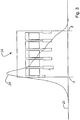
- FIG. 3 shows the course of the axial field distribution of an optimized illumination condenser 10. Since the source crossover 31 o is preferably imaged infinitely, the optimization of the illumination condenser 10 is such that the quotient of crossover error disc and crossover diameter is minimal when the crossover in Borderline case goes against infinity.
- the magnetic field strength 24 of the illumination condenser 10 according to the invention is shown as a function of the position with respect to the axis 21 of the beam path. It can be seen that the magnetic field strength 24 increases sharply in the region of point A and reaches a maximum at a short distance. Starting from the maximum, the magnetic field strength 24 then drops continuously and reaches the value zero approximately at the point B.
Landscapes
- Engineering & Computer Science (AREA)
- Chemical & Material Sciences (AREA)
- Nanotechnology (AREA)
- Physics & Mathematics (AREA)
- Crystallography & Structural Chemistry (AREA)
- Manufacturing & Machinery (AREA)
- General Physics & Mathematics (AREA)
- Condensed Matter Physics & Semiconductors (AREA)
- Analytical Chemistry (AREA)
- Mathematical Physics (AREA)
- Theoretical Computer Science (AREA)
- Electron Beam Exposure (AREA)
- Exposure And Positioning Against Photoresist Photosensitive Materials (AREA)
- Investigating Or Analyzing Materials By The Use Of Magnetic Means (AREA)
- Non-Portable Lighting Devices Or Systems Thereof (AREA)
Description
- Die Erfindung betrifft einen Beleuchtungskondensor für ein Partikeloptik - Projektionssystem.
- In der Halblefterfertigung ist es oft erforderlich, dass ein Objekt (Maske bzw. Vielstrahlmodulator) mit Hilfe eine Kondensors telezentrisch beleuchtet wird, dabei wird üblicherweise aufgrund der sphärischen Aberration des Kondensors der partielle Crossover eines achsfernen Punktes auf der Maske von der Achse weggelenkt, was zu zusätzlichen Fehlern (schräger Strahleinfall im Target, Astigmatismus und/oder Verzeichnung) führt. Die Außeraxialität des Crossovers führt zu zusätzlichen Aberrationen im Partikularoptik-Projektionsgerät, da die Strahlen die Linsenfelder in größerer Entfernung von der Achse passieren. Die Außeraxialität des partiellen Crossovers wird wesentlich verursacht durch die sphärische Aberration des Beleuchtungs-Kondensors. Die Wirkung der sphärischen Aberration des Beleuchtungs-Kondensors ist proportional zur dritten Potenz der im Crossover wirksamen Apertur. Diese Apertur ist bei Großfeld-Partikeloptik-Projektionssystemen sehr groß, typisch 100 mrad. Sie kann bei vorhandenem Beleuchtungskondensor nur durch einen sehr großen Abstand zwischen der Partikel-Quelle und der Maske / des Multiapertur-Vielstrahlmodulators reduziert werden. Dies führt jedoch zu extremer Bauhöhe des Partikularstrahl-Projektionsgerätes.
- Im
US-Patent 4,468,563 und in derDE 15 64 761 A1 werden jeweils Zweispaltlinsen für Elektronenmikroskope beschrieben, bei denen eine Umschaltung von geringer zu starker Fokussierung durch einen ferromagnetischen Shunt (magnetischen Bypass) in einem der Polspalte möglich ist. Dabei wird die Spaltlinse, die aus nur einem Eisenkreis mit einer Wicklung besteht, über eine mehr oder minder starke Anregung zwischen Ein- oder Zweispaltlinse umgeschaltet - Im
U.S. Patent 5,742,062 ist eine elektrostatische Linse beschrieben, die aus einer Vielzahl ringförmiger Elektroden besteht, an die verschiedene Potentiale angelegt sind. Diese Linse ist geeignet, eine großflächige, parallele Beleuchtung eines Objektes (Maske) mit geladenen Teilchen zu ermöglichen. Durch geeignete Wahl der Elektrodenpotentiale ist es möglich, die Linsenaberrationen zu minimieren. Nachteilig ist der große technische Aufwand zur Bereitstellung einer Vielzahl unterschiedlicher Potentiale mit hoher zeitlicher Konstanz. Für den Fall hoher Strahlenergie (50...200keV) sind die notwendigen Isolationsstrecken lang, die Vakuumdurchführungen entsprechend groß und damit auch das benötigte Vakuumvolumen für diese Anordnung- Daraus folgt der Nachteil, dass die Abschirmung des Partikelstrahls gegen magnetische Störfelder sehr aufwendig ist, da geeignete Abschimizylinder z.B. aus Mu-Metall einen großen Radius und dicke Wandstärke benötigen. Weiterhin ist die Gasabgabe der großen Oberfläche der Elektroden und Isolatoren nachteilig für den angestrebten niedrigen Enddruck im Rezipienten und eine entsprechend geringe Kontaminationsrate. - Das Paper von Rose zur magnetisch-elektrostatischen Multielektroden-Linse; D. Preikszas, H. Rose, Optik 100 (1995), 179; offenbart eine kombinierte magnetisch-elektrostatische Linse, die aus einer Anzahl identischer Elemente (Aperturen, Ringströme) besteht, die so angesteuert werden, dass Aberrationen weitgehend unterdrückt werden.
- Der Stand der Technik ist dadurch gekennzeichnet, dass die sphärische Aberration des Beleuchtungs-Kondensors in Partikutarstrahi-Projektionsgeräten nicht bzw. nur über die große radiale Ausdehnung des Kondensors reduziert wird. Das beschränkt wesentlich die mögliche Größe der Maske und/oder des Muttiapertur-Strahimodulators. Es gibt lediglich Versuche, mit elektrostatischen Kondensorlinsen, die sehr viele Elektroden besitzen (Muttiapertur-Kondensor), eine solche Form des elektrostatischen Feldes des Kondensors zu erzielen, dass die sphärische Aberration weitgehend unterdrückt wird. Ein solcher elektrostatischer Multiapertur-Kondensor erfordert jedoch eine Vielzahl von Hochspannungs-Versorgungen für die einzelnen Elektroden und ist deshalb nur beschränkt verwendbar.
- Der Erfindung liegt die Aufgabe zugrunde, ein Projektionsgerät zur Belichtung von Substraten derart auszugestalten, dass eine Maske oder ein Multiapertur-Strahlmodulator vorzugsweise telezentrisch beleuchtet werden. Dabei soll die Bauhöhe des Projektionsgeräts in vernünftigen Grenzen gehalten werden.
- Diese Aufgabe wird durch ein System mit den Merkmalen des Anspruchs 1 gelöst.
- Es ist von Vorteil, wenn der Beleuchtungskondensor für ein Partikeloptik - Projektionssystem aus einer magnetischen Linse aufgebaut ist, und dass die magnetische Linse mehrere Spalte umfasst. Dabei ist die Anzahl der Spalte zweckmäßig größer oder gleich fünf.
- Vorteilhaft ist in der aus einer Sequenz von mehreren partiellen Linsen zusammengesetzten magnetischen Linse mit jeweils separaten Wicklungen jede Wicklung einzeln ansteuerbar. Mindestens zwei benachbarte partielle Linsen besitzen vorzugsweise einen gemeinsamen Polschuh.
- Ferner ist von Vorteil, wenn der Beleuchtungskondensor derart ausgestaltet ist, dass die Aberration des Quell-Crossover minimiert ist, wobei die radiale Ausdehnung, der maximale Bohrungsradius Rk des Beleuchtungskondensors einen Wert aufweist, der kleiner als 150 mm ist.
- Weiterhin kann es von Vorteil sein, dass ein derartiger Beleuchtungskondensor mit einer elektrostatischen Zerstreuungslinse kombiniert wird, was die Aberrationen weiter minimiert.
- Des Weiteren kann es von Vorteil sein, dass ein derartiger Beleuchtungskondensor als Mehrspalt-Dublette (Zwei Mehrspalt-Linsen hintereinander mit entgegengesetzter Bilddrehung) ausgeführt wird. In diesem Fall würden sich anisotrope Restfehler kompensieren.
- Es ist von besonderem Vorteil, wenn die Beleuchtung der Maske derart erfolge, dass der partielle Crossover eines Punktes auf der Maske oder des Multiapertur-Strahlmodulators so weit wie möglich auf der optischen Achse des Partikelstrahl-Projektionsgerätes verbleibt.
- In der Zeichnung ist der Erfindungsgegenstand schematisch dargestellt und wird anhand der Figuren nachfolgend beschrieben. Dabei zeigen:
-
Fig. 1 eine schematische Darstellung des Strahlengangs in einem Partikeloptik - Projektionssystem; -
Fig. 2 ein Ausführungsbeispiel eines erfindungsgemäßen magnetischen Beleuchtungskondensors; und -
Fig. 3 eine Ansicht der axialen Feldverteilung des magnetischen Beleuchtungskondensors; -
Fig. 1 zeigt den prinzipiellen Strahlengang in einem Partikeloptik - Projektionssystem 2. In der nachstehenden Beschreibung wird das Partikeloptik - Projektionssystem 2 beschrieben, dabei sind die Partikel Elektronen. Von einer Elektronenkanone (Partikelkanone) 30 wird ein Elektronenstrahl 31 erzeugt, der sich in Richtung einer elektronenoptischen Achse 32 ausbreitet. Die aus der Elektronenkanone 30 austretenden Elektronen weisen einen Quell-Crossover 31o auf. Der Elektronenkanone 30 ist eine Strahlzentriereinrichtung 33 nachgeschaltet, die den Elektronenstrahl 31 symmetrisch um die optische Achse 32 ausrichtet. Nach der Strahlzentriereinrichtung durchläuft der Elektronenstrahl 31 einen Beleuchtungskondensor 10, der aus dem anfänglich divergenten Elektronenstrahl 31 einen parallelen Strahl formt. Der durch den Beleuchtungskondensor 10 geformte Strahl besitzt einen Durchmesser, über den die Intensität homogen verteilt ist. Nach dem Beleuchtungskondensor 10 ist eine Aperturplatte 34, mit einer Vielzahl von Öffnungen 35 für den Elektronenstrahl vorgesehen. Nach der Aperturplatte 34 folgt eine Beschleunigungslinse 36, an die sich mindestens eine magnetische Linse 50 zur Strahldrehung anschließt. In dem hier dargestellten Ausführungsbeispiel sind zwei weitere magnetische Linsen 37 gezeigt, die der verkleinernden Abbildung der Aperturplatte 34 dienen. Bevor der Elektronenstrahl 31 auf ein Target 40 trifft, das z.B. ein Wafer ist, durchläuft der Elektronenstrahl 31 eine Objektivlinse 38. Die Objektivlinse 38 ist mit einer Vielzahl von Elementen ausgestattet. Vor und nach einem zweiten Crossover 312 des Elektronenstrahls 31 ist eine Ablenkeinrichtung 42 vorgesehen. Die Ablenkeinrichtung 42 dient zum Auslenken und zur Lagebestimmung des Elektronenstrahls 31 bzw. der Vielzahl der Einzelstrahlen, die durch die Aperturplatte 34 erzeugt werden. Ferner ist eine Fokussierlinse 44 für die dynamische Fokussierung und eine Spulenanordnung 46, die als Stigmator wirkt, vorgesehen. Die Objektivlinse 38 besitzt an der dem Target 40 gegenüberliegenden Stelle einen Höhensensor 48 und einen Detektor für die vom Target 40 rückgestreuten Elektronen. -
Fig. 2 zeigt eine Ausführungsform eines erfindungsgemäßen Beleuchtungskondensors 10. Der Beleuchtungskondensor 10 besteht aus einer magnetischen Linse 11, die aus einer Vielzahl von Spalten 12 aufgebaut ist. Bevorzugt ist eine Spaltenzahl ny >= 5. Der Beleuchtungskondensor 10 stellt eine magnetische Linse mit einer langen Brennweite dar. Die Brennweite beträgt typisch um die 500mm. Der aus dem Beleuchtungskondensor 10 austretende Partikelstrahl beleuchtet, vorzugsweise telezentrisch, eine Maske oder einen Multiapertur-Strahlmodulator oder eine Aperturplatte 40. Dazu ist es erforderlich, dass der Quell-Crossover 31o im objektseitigen Brennpunkt des Beleuchtungskondensors 10 steht, d.h., der Quell-Crossover 31o wird ins Unendliche abgebildet. Bei dem inFig. 2 dargestellten Ausführungsbeispiel eines erfindungsgemäßen magnetischen Beleuchtungskondensors 10 umfasst die magnetische Linse 11 fünf Spalte. Der Beleuchtungskondensor 10 besteht demzufolge aus einer Sequenz von mehreren partiellen Linsen 14, 15, 16, 17 und 18, die im Strahlengang 20 des Partikularoptik-Projektionsgerätes 2 vor der Maske oder einer Aperturplatte 40 angeordnet sind und diese vorzugsweise telezentrisch beleuchten. Jede partielle Linse 14, 15, 16, 17, 18 hat dabei eine erste Wicklung 14a, 15a, 16a, 17a, 18a mit separat einstellbarer Erregung. Vorteilhaft kann die Einstellung der separaten Erregungen der partiellen Linsen auch über eine individuelle Windungszahl für die ersten Wicklungen 14a, 15a, 16a, 17a, 18a erfolgen, wobei die Stromversorgung der in Reihenschaltung betriebenen Wicklungen dann aus einer gemeinsamen Stromquelle erfolgt. Weiterhin kann es von Vorteil sein, zusätzlich zu den ersten Wicklungen (Grobwicklungen) 14a, 15a, 16a, 17a, 18a,, zweite Wicklungen (Feinwicklungen) 14b, 15b, 16b, 17b, 18b vorzusehen. Die zweiten Wicklungen (Feinwicklungen) 14b, 15b, 16b, 17b, 18b besitzen vorzugsweise individuelle Windungszahlen für jede partielle Linse 14, 15, 16, 17, 18. Mittels Erregungsvariation der in Reihenschaltung betriebenen Feinwicklungen kann auf einfache Weise eine feinfühlige Brennweittenvariation erfolgen, wenn gleichzeitig die Reihenschaltung der Grobwicklungen aus einer gemeinsamen Konstantstromquelle erfolgt. Zwei benachbarte partielle Linsen besitzen einen gemeinsamen Polschuh 19. Die Erregungen und Spalte der partiellen Linsen 14, 15, 16, 17, 18 sowie die Durchmesser der Polschuhe 19 sind voneinander verschieden. Bei dem inFig. 2 dargestellten Ausführungsbeispiel mit fünf Spalten können insgesamt sechzehn Parameter individuell dabei so gewählt werden, dass die sphärische Aberration des Beleuchtungskondensors 10 bei der Abbildung des Quell-Crossover 31o minimiert ist. Dies geschieht unter der Nebenbedingung, dass die radiale Ausdehnung, der maximale Bohrungsradius Rk des Beleuchtungskondensors 10 eine gewisse Größe nicht übersteigt. Eine typische Größe für den Bohrungsradius Rk des Beleuchtungskondensors 10 ist dabei kleiner als 150 mm. Der Beleuchtungskondensor 10 ist in der Darstellung derFig. 2 lediglich zur Hälfte dargestellt. Der Beleuchtungskondensor ist um eine Achse 21 des Strahlengangs 20 rotationssymmetrisch. Der Strahlengang 20 durchläuft den Beleuchtungskondensor 10 von einem Strahleintritt A zu einem Strahlaustritt B. Die magnetischen Feldlinien 22 bilden sich bei dem Beleuchtungskondensor 10 der gegenwärtigen Erfindung derart aus, dass sie weiter von der Achse 21 des Strahlengangs 20 zurücktreten je mehr man sich dem Punkt B des Beleuchtungskondensors 10 nähert. Mit anderen Worten, ist die durch die magnetischen Feldlinien 22 dargestellte magnetische Feldstärke 24 am Strahlaustritt A des Beleuchtungskondensors 10 geringer als am Strahleintritt B. -
Figur 3 zeigt den Verlauf der axialen Feldverteilung eines optimierten Beleuchtungskondensors 10. Da der Quell-Crossover 31o vorzugsweise ins Unendliche abgebildet wird, erfolgt die Optimierung des Beleuchtungskondensors 10 derart, dass der Quotient aus Crossover-Fehlerscheibchen und Crossover-Durchmesser minimal wird, wenn der Crossover im Grenzfall gegen Unendlich geht. Die magnetische Feldstärke 24 des erfindungsgemäßen Beleuchtungskondensors 10 ist in Abhängigkeit von der Lage bezüglich der Achse 21 des Strahlenganges dargestellt. Dabei ist zu erkennen, dass die magnetische Feldstärke 24 im Bereich von Punkt A stark zunimmt und auf kurzer Distanz ein Maximum erreicht. Vom Maximum ausgehend fällt die magnetische Feldstärke 24 dann kontinuierlich ab und erreicht in etwa beim Punkt B den Wert Null. - Die Erfindung wurde bezüglich eines besonderen Ausführungsbeispiels beschrieben, es ist jedoch für jeden Fachmann selbstverständlich, dass im Rahmen des handwerklichen Könnens eines Fachmanns Änderungen und Abwandlungen durchgeführt werden können ohne dabei den Schutzbereich der nachstehenden Patentansprüche zu verlassen.
Claims (14)
- Beleuchtungskondensor (10) für ein Partikeloptik-Projektionssystem mit einem Beleuchtungskondensor (10) aus einer magnetischen Linse (11), die mehrere Spalte aufweist, dadurch gekennzeichnet, dass die magnetische Linse aus einer Sequenz von mehreren partiellen Linsen (14, 15, 16, 17, 18) aufgebaut ist, wobei
die partiellen Linsen (14, 15, 16, 17, 18) jeweils eine separate Wicklung (14a, 15a, 16a, 17a, 18a) aufweisen. - Beleuchtungskondensor nach Anspruch 1, dadurch gekennzeichnet, dass die Anzahl der Spalte größer als fünf ist.
- Beleuchtungskondensor nach Anspruch 1, dadurch gekennzeichnet, dass die Anzahl der Spalte gleich fünf ist.
- Beleuchtungskondensor nach Anspruch 1, dadurch gekennzeichnet, dass jede der separaten Wicklungen (14a, 15a, 16a, 17a, 18a) der mehreren partiellen Linsen (14, 15, 16, 17, 18) einzeln ansteuerbar ist.
- Beleuchtungskondensor nach Anspruch 1, dadurch gekennzeichnet, dass jede der mehreren partiellen Linsen (14, 15, 16, 17, 18) erste separate Wicklungen (14a, 15a, 16a, 17a, 18a) und zweite separate Wicklungen (14b, 15b, 16b, 17b, 18b) enthält, wobei das Verhältnis der Windungszahlen der ersten (14a,15a,16a,17a,18a) bzw. der zweiten Wicklungen (14b,15b,16b,17b,18b) so gewählt ist, dass die partiellen Linsen (14, 15, 16, 17, 18) die gewünschte Erregung erhalten, wenn die ersten Wicklungen (14a, 15a, 16a, 17a, 18a) in Reihenschaltung und die zweiten Wicklungen (14b, 15b, 16b, 17b, 18b) in Reihenschaltung betrieben werden.
- Beleuchtungskondensor nach Anspruch 5, dadurch gekennzeichnet, dass die ersten Wicklungen (Grobwicklungen) (14a, 15a, 16a, 17a, 18a) der partiellen Linsen (14, 15, 16, 17, 18) von demselben konstanten Strom durchflutet sind und die zweiten Wicklungen (Feinwicklungen) (14b, 15b, 16b, 17b, 18b) der partiellen Linsen (14, 15, 16,17,18) infolge individueller Windungszahlen in einer Reihenschaltung unterschiedliche Erregung aufweisen, wenn sie vom selben Strom durchflutet sind, wobei mittels Stromvariation der in Reihenschaltung betriebenen Feinwicklungen (14b, 15b, 16b, 17b, 18b) eine feinfühlige Brennweitenvariation einstellbar ist.
- Beleuchtungskondensor nach Anspruch 1, dadurch gekennzeichnet, dass mindestens zwei benachbarte, partielle Linsen (14, 15. 16, 17, 18) einen gemeinsamen Polschuh (19) besitzen, wobei die zwischen den Polschuhen (19) befindlichen Spalte der partiellen Linsen (14, 15, 16, 17, 18) und/oder die Durchmesser der Polschuhe (19) voneinander verschieden sind.
- Beleuchtungskondensor nach einem der Ansprüche 1 bis 7, dadurch gekennzeichnet, dass das Partikeloptik-Projektionssystem (2) eine optische Achse (32) definiert, um die der Beleuchtungskondensor (10) rotationssymmetrisch aufgebaut ist.
- Beleuchtungskondensor nach Anspruch 8, dadurch gekennzeichnet, dass die Aberration eines Quell-Crossover (310) minimiert ist, wobei ein maximaler Bohrungsradius Rk des Beleuchtungskondensors (10) einen Wert aufweist, der kleiner als 150 mm ist.
- Beleuchtungskondensor nach Anspruch 9, dadurch gekennzeichnet, dass die magnetische Feldstärke (24) Ober Jede der partiellen Linsen (14, 15, 16, 17, 18) geringer wird, so dass am Strahlaustritt (B) annähernd der Wert Null erreicht ist.
- Beleuchtungskondensor nach einem der Ansprüche 1 bis 10, dadurch gekennzeichnet, dass die magnetische Feldstärke (24) über die partiellen Linsen (14, 15, 18, 17, 18) so eingestellt ist, dass der Quell-Crossover (310) einer Elektronenkanone (30) im objektseitigenseitigen Brennpunkt des Beleuchtungskondensor (10) steht und in das Unendliche abgebildet ist.
- Beleuchtungskondensor nach einem der Ansprüche 1 bis 11, dadurch gekennzeichnet, dass die magnetische Feldstärke (24) über die partiellen Linsen (14, 15, 16, 17, 18) so eingestellt ist, dass der Beleuchtungskondensor (10) eine lange Brennweite aufweist, die um die 500 mm beträgt.
- Beleuchtungskondensor nach einem der Ansprüche 1 bis 12, dadurch gekennzeichnet, dass der Beleuchtungskondensor mit einer elektrostatischen Zerstreuungslinse kombiniert ist.
- Beleuchtungskondensor nach einem der Ansprüche 1 bis 12, dadurch gekennzeichnet, dass der Beleuchtungskondensor aus einer Dublette von zwei Mehrspalt-Linsen zusammengesetzt ist.
Applications Claiming Priority (2)
| Application Number | Priority Date | Filing Date | Title |
|---|---|---|---|
| DE102004019835A DE102004019835B4 (de) | 2004-04-23 | 2004-04-23 | Beleuchtungskondensor für ein Partikeloptik-Projektionssystem |
| PCT/EP2005/050941 WO2005104170A1 (de) | 2004-04-23 | 2005-03-03 | Beleuchtungskondensor für ein partikeloptik - projektionssystem |
Publications (2)
| Publication Number | Publication Date |
|---|---|
| EP1738392A1 EP1738392A1 (de) | 2007-01-03 |
| EP1738392B1 true EP1738392B1 (de) | 2012-05-09 |
Family
ID=34961043
Family Applications (1)
| Application Number | Title | Priority Date | Filing Date |
|---|---|---|---|
| EP05716895A Expired - Lifetime EP1738392B1 (de) | 2004-04-23 | 2005-03-03 | Beleuchtungskondensor für ein partikeloptik - projektionssystem |
Country Status (6)
| Country | Link |
|---|---|
| US (1) | US7601969B2 (de) |
| EP (1) | EP1738392B1 (de) |
| JP (1) | JP5281792B2 (de) |
| AT (1) | ATE557415T1 (de) |
| DE (1) | DE102004019835B4 (de) |
| WO (1) | WO2005104170A1 (de) |
Families Citing this family (6)
| Publication number | Priority date | Publication date | Assignee | Title |
|---|---|---|---|---|
| US7851755B2 (en) * | 2006-12-20 | 2010-12-14 | Jeol Ltd. | Apparatus for detecting backscattered electrons in a beam apparatus |
| JP5928320B2 (ja) | 2012-12-07 | 2016-06-01 | 株式会社日立製作所 | 電気自動車向けナビゲーションシステム |
| JP6242314B2 (ja) * | 2014-09-11 | 2017-12-06 | 住友重機械イオンテクノロジー株式会社 | イオン注入装置及びイオンビームの調整方法 |
| JP7354037B2 (ja) * | 2020-03-23 | 2023-10-02 | 株式会社日立ハイテクサイエンス | 集束イオンビーム加工装置 |
| CN112769025A (zh) * | 2020-12-30 | 2021-05-07 | 中国科学院微电子研究所 | 光学整形装置及方法 |
| KR102834465B1 (ko) * | 2023-01-16 | 2025-07-15 | 가부시키가이샤 뉴플레어 테크놀로지 | 멀티 하전 입자빔 묘화 장치 |
Family Cites Families (23)
| Publication number | Priority date | Publication date | Assignee | Title |
|---|---|---|---|---|
| DE1019407B (de) * | 1943-12-09 | 1957-11-14 | Dr Heinrich Herbst | Elektronenoptisches Linsensystem fuer Elektronen- oder Ionenmikroskope |
| DE1564761C3 (de) | 1966-11-18 | 1974-07-04 | Siemens Ag, 1000 Berlin Und 8000 Muenchen | Elektromagnetische Linse für ein Korpuskularstrahlgerät mit mehreren Linsenspalten |
| DE1614123B1 (de) * | 1967-02-24 | 1970-07-02 | Max Planck Gesellschaft | Korpuskularstrahlgeraet,insbesondere Elektronenmikroskop |
| US3686527A (en) * | 1969-12-12 | 1972-08-22 | Sanders Associates Inc | High-speed synthesized field focus coil |
| DE2627176B2 (de) * | 1976-06-15 | 1978-09-14 | Siemens Ag, 1000 Berlin Und 8000 Muenchen | Elektronenstrahloptisches Projektionsgerät mit einer langbrennweitigen magnetischen Linse |
| JPS5379369A (en) * | 1976-12-24 | 1978-07-13 | Fujitsu Ltd | Electron lens |
| JPS55128238A (en) * | 1979-03-28 | 1980-10-03 | Hitachi Ltd | Electron lens device |
| JPS57206173A (en) * | 1981-06-15 | 1982-12-17 | Nippon Telegr & Teleph Corp <Ntt> | Focusing deflecting device for charged corpuscule beam |
| JPS587755A (ja) * | 1981-07-06 | 1983-01-17 | Jeol Ltd | 電子レンズ |
| JPS5983336A (ja) * | 1982-11-02 | 1984-05-14 | Jeol Ltd | 荷電粒子線集束偏向装置 |
| US4544847A (en) * | 1983-07-28 | 1985-10-01 | Varian Associates, Inc. | Multi-gap magnetic imaging lens for charged particle beams |
| US5442182A (en) * | 1992-11-06 | 1995-08-15 | Hitachi, Ltd. | Electron lens |
| JPH06325719A (ja) * | 1993-05-14 | 1994-11-25 | Nikon Corp | 荷電粒子線装置 |
| JPH08274020A (ja) * | 1995-02-13 | 1996-10-18 | Ims Ionen Mikrofab Syst Gmbh | 荷電粒子による投影リソグラフィー装置 |
| DE19734059B4 (de) * | 1996-08-20 | 2007-01-11 | Ims-Ionen Mikrofabrikations Systeme Ges.M.B.H. | Anordnung für Schattenwurflithographie |
| US6064071A (en) * | 1997-04-23 | 2000-05-16 | Nikon Corporation | Charged-particle-beam optical systems |
| US6222197B1 (en) * | 1997-08-21 | 2001-04-24 | Nikon Corporation | Charged-particle-beam pattern-transfer methods and apparatus |
| JPH11339708A (ja) * | 1998-03-25 | 1999-12-10 | Nikon Corp | 縮小投影レンズ |
| US6420713B1 (en) * | 1999-04-28 | 2002-07-16 | Nikon Corporation | Image position and lens field control in electron beam systems |
| US6566664B2 (en) * | 2000-03-17 | 2003-05-20 | Canon Kabushiki Kaisha | Charged-particle beam exposure apparatus and device manufacturing method |
| DE10034412A1 (de) * | 2000-07-14 | 2002-01-24 | Leo Elektronenmikroskopie Gmbh | Verfahren zur Elektronenstrahl-Lithographie und elektronen-optisches Lithographiesystem |
| DE10044199B9 (de) * | 2000-09-07 | 2005-07-28 | Carl Zeiss Smt Ag | Ablenkanordnung und Projektionssystem für geladene Teilchen |
| US6727507B2 (en) * | 2001-01-22 | 2004-04-27 | Leepl Corporation | Electron beam proximity exposure apparatus and method |
-
2004
- 2004-04-23 DE DE102004019835A patent/DE102004019835B4/de not_active Expired - Fee Related
-
2005
- 2005-03-03 AT AT05716895T patent/ATE557415T1/de active
- 2005-03-03 EP EP05716895A patent/EP1738392B1/de not_active Expired - Lifetime
- 2005-03-03 US US11/587,227 patent/US7601969B2/en not_active Expired - Fee Related
- 2005-03-03 JP JP2007508888A patent/JP5281792B2/ja not_active Expired - Lifetime
- 2005-03-03 WO PCT/EP2005/050941 patent/WO2005104170A1/de not_active Ceased
Also Published As
| Publication number | Publication date |
|---|---|
| US20080035853A1 (en) | 2008-02-14 |
| US7601969B2 (en) | 2009-10-13 |
| DE102004019835A1 (de) | 2006-03-02 |
| EP1738392A1 (de) | 2007-01-03 |
| JP2007534124A (ja) | 2007-11-22 |
| DE102004019835B4 (de) | 2007-08-02 |
| ATE557415T1 (de) | 2012-05-15 |
| JP5281792B2 (ja) | 2013-09-04 |
| WO2005104170A1 (de) | 2005-11-03 |
Similar Documents
| Publication | Publication Date | Title |
|---|---|---|
| DE102019004124B4 (de) | Teilchenstrahl-System zur azimutalen Ablenkung von Einzel-Teilchenstrahlen sowie seine Verwendung und Verfahren zur Azimut-Korrektur bei einem Teilchenstrahl-System | |
| DE102018007652B4 (de) | Teilchenstrahl-System sowie Verfahren zur Stromregulierung von Einzel-Teilchenstrahlen | |
| EP0530640B1 (de) | Abbildungssystem für Strahlung geladener Teilchen mit Spiegelkorrektor | |
| EP1277221B1 (de) | Strahlerzeugungssystem für elektronen oder ionenstrahlen hoher monochromasie oder hoher stromdichte | |
| EP0461442B1 (de) | Teilchenstrahlgerät | |
| DE10044199A1 (de) | Teilchenoptische Komponente und System mit Teilchenoptischer Komponente | |
| DE3222275C2 (de) | Ablenk- und Fokussiersystem für einen Strahl aus geladenen Teilchen | |
| EP4004962A1 (de) | Teilchenstrahlsystem und seine verwendung zum flexiblen einstellen der stromstärke von einzel-teilchenstrahlen | |
| DE112015001235B4 (de) | Vorrichtung und verfahren zur abbildung mittels eines elektronenstrahls unter verwendung eines monochromators mit doppeltem wien-filter sowie monochromator | |
| DE112016005577B4 (de) | Ladungsträgerstrahlvorrichtung und Verfahren zur Einstellung ihrer optischen Achse | |
| DE2752598C3 (de) | Verfahren zum Betrieb einer elektromagnetischen fokussierenden elektronen-optischen Linsenanordnung und Linsenanordnung hierfür | |
| DE102013113476B4 (de) | Elektromagnetische Objektivlinse für ein Multisäulen-Elektronenstrahl-Belichtungsgerät sowie Elektronenstrahl-Belichtungsgerät | |
| DE102020123567A1 (de) | Vielzahl-Teilchenstrahl-System mit Kontrast-Korrektur-Linsen-System | |
| DE102022120496B4 (de) | Teilchenoptische Anordnung, insbesondere Vielstrahl-Teilchenmikroskop, mit einer Magnetanordnung zum Separieren eines primären und eines sekundären teilchenoptischen Strahlenganges | |
| DE102015210893B4 (de) | Analyseeinrichtung zur Analyse der Energie geladener Teilchen und Teilchenstrahlgerät mit einer Analyseeinrichtung | |
| DE102004019834B4 (de) | Korrekturlinsen-System für ein Partikelstrahl-Projektionsgerät | |
| DE102004019835B4 (de) | Beleuchtungskondensor für ein Partikeloptik-Projektionssystem | |
| DE102010041813A1 (de) | Teilchenstrahlgerät und Verfahren zur Untersuchung und/oder Bearbeitung eines Objekts | |
| DE102023119451A1 (de) | Vielstrahl-Teilchenstrahlsystem mit elektrostatischer Boosterlinse, Verfahren zum Betreiben eines Vielstrahl-Teilchenstrahlsystems und zugehöriges Computerprogrammprodukt | |
| EP3053182B1 (de) | Strahlungserzeugungsanlage | |
| DE10255032A1 (de) | Verringerung von Aberrationen, die in einem Rasterelektronenmikroskop oder Ähnlichem durch ein Wien-Filter erzeugt werden | |
| DE69913100T2 (de) | Projektionslithographie mittels ladungsträgern | |
| DE2515550B1 (de) | Korpuskularstrahloptisches geraet zur abbildung einer maske auf ein zu bestrahlendes praeparat | |
| DE102020109441B4 (de) | Verfahren zum Betreiben einer Objektivlinsenanordnung, Objektivlinsenanordnung und Teilchenstrahlmikroskop | |
| DE19633320C2 (de) | Verfahren zur verkleinernden Abbildung einer Maske auf einem Substrat und Vorrichtung zur Durchführung des Verfahrens |
Legal Events
| Date | Code | Title | Description |
|---|---|---|---|
| PUAI | Public reference made under article 153(3) epc to a published international application that has entered the european phase |
Free format text: ORIGINAL CODE: 0009012 |
|
| 17P | Request for examination filed |
Effective date: 20061107 |
|
| AK | Designated contracting states |
Kind code of ref document: A1 Designated state(s): AT BE BG CH CY CZ DE DK EE ES FI FR GB GR HU IE IS IT LI LT LU MC NL PL PT RO SE SI SK TR |
|
| DAX | Request for extension of the european patent (deleted) | ||
| 17Q | First examination report despatched |
Effective date: 20080731 |
|
| GRAP | Despatch of communication of intention to grant a patent |
Free format text: ORIGINAL CODE: EPIDOSNIGR1 |
|
| GRAS | Grant fee paid |
Free format text: ORIGINAL CODE: EPIDOSNIGR3 |
|
| GRAA | (expected) grant |
Free format text: ORIGINAL CODE: 0009210 |
|
| AK | Designated contracting states |
Kind code of ref document: B1 Designated state(s): AT BE BG CH CY CZ DE DK EE ES FI FR GB GR HU IE IS IT LI LT LU MC NL PL PT RO SE SI SK TR |
|
| REG | Reference to a national code |
Ref country code: GB Ref legal event code: FG4D Free format text: NOT ENGLISH |
|
| REG | Reference to a national code |
Ref country code: CH Ref legal event code: EP Ref country code: AT Ref legal event code: REF Ref document number: 557415 Country of ref document: AT Kind code of ref document: T Effective date: 20120515 |
|
| REG | Reference to a national code |
Ref country code: IE Ref legal event code: FG4D Free format text: LANGUAGE OF EP DOCUMENT: GERMAN |
|
| REG | Reference to a national code |
Ref country code: DE Ref legal event code: R096 Ref document number: 502005012721 Country of ref document: DE Effective date: 20120705 |
|
| REG | Reference to a national code |
Ref country code: NL Ref legal event code: VDEP Effective date: 20120509 |
|
| REG | Reference to a national code |
Ref country code: LT Ref legal event code: MG4D Effective date: 20120509 |
|
| PG25 | Lapsed in a contracting state [announced via postgrant information from national office to epo] |
Ref country code: LT Free format text: LAPSE BECAUSE OF FAILURE TO SUBMIT A TRANSLATION OF THE DESCRIPTION OR TO PAY THE FEE WITHIN THE PRESCRIBED TIME-LIMIT Effective date: 20120509 Ref country code: SE Free format text: LAPSE BECAUSE OF FAILURE TO SUBMIT A TRANSLATION OF THE DESCRIPTION OR TO PAY THE FEE WITHIN THE PRESCRIBED TIME-LIMIT Effective date: 20120509 Ref country code: IS Free format text: LAPSE BECAUSE OF FAILURE TO SUBMIT A TRANSLATION OF THE DESCRIPTION OR TO PAY THE FEE WITHIN THE PRESCRIBED TIME-LIMIT Effective date: 20120909 Ref country code: FI Free format text: LAPSE BECAUSE OF FAILURE TO SUBMIT A TRANSLATION OF THE DESCRIPTION OR TO PAY THE FEE WITHIN THE PRESCRIBED TIME-LIMIT Effective date: 20120509 Ref country code: PL Free format text: LAPSE BECAUSE OF FAILURE TO SUBMIT A TRANSLATION OF THE DESCRIPTION OR TO PAY THE FEE WITHIN THE PRESCRIBED TIME-LIMIT Effective date: 20120509 Ref country code: CY Free format text: LAPSE BECAUSE OF FAILURE TO SUBMIT A TRANSLATION OF THE DESCRIPTION OR TO PAY THE FEE WITHIN THE PRESCRIBED TIME-LIMIT Effective date: 20120509 |
|
| PG25 | Lapsed in a contracting state [announced via postgrant information from national office to epo] |
Ref country code: GR Free format text: LAPSE BECAUSE OF FAILURE TO SUBMIT A TRANSLATION OF THE DESCRIPTION OR TO PAY THE FEE WITHIN THE PRESCRIBED TIME-LIMIT Effective date: 20120810 Ref country code: SI Free format text: LAPSE BECAUSE OF FAILURE TO SUBMIT A TRANSLATION OF THE DESCRIPTION OR TO PAY THE FEE WITHIN THE PRESCRIBED TIME-LIMIT Effective date: 20120509 Ref country code: PT Free format text: LAPSE BECAUSE OF FAILURE TO SUBMIT A TRANSLATION OF THE DESCRIPTION OR TO PAY THE FEE WITHIN THE PRESCRIBED TIME-LIMIT Effective date: 20120910 |
|
| PG25 | Lapsed in a contracting state [announced via postgrant information from national office to epo] |
Ref country code: RO Free format text: LAPSE BECAUSE OF FAILURE TO SUBMIT A TRANSLATION OF THE DESCRIPTION OR TO PAY THE FEE WITHIN THE PRESCRIBED TIME-LIMIT Effective date: 20120509 Ref country code: SK Free format text: LAPSE BECAUSE OF FAILURE TO SUBMIT A TRANSLATION OF THE DESCRIPTION OR TO PAY THE FEE WITHIN THE PRESCRIBED TIME-LIMIT Effective date: 20120509 Ref country code: CZ Free format text: LAPSE BECAUSE OF FAILURE TO SUBMIT A TRANSLATION OF THE DESCRIPTION OR TO PAY THE FEE WITHIN THE PRESCRIBED TIME-LIMIT Effective date: 20120509 Ref country code: EE Free format text: LAPSE BECAUSE OF FAILURE TO SUBMIT A TRANSLATION OF THE DESCRIPTION OR TO PAY THE FEE WITHIN THE PRESCRIBED TIME-LIMIT Effective date: 20120509 Ref country code: NL Free format text: LAPSE BECAUSE OF FAILURE TO SUBMIT A TRANSLATION OF THE DESCRIPTION OR TO PAY THE FEE WITHIN THE PRESCRIBED TIME-LIMIT Effective date: 20120509 Ref country code: DK Free format text: LAPSE BECAUSE OF FAILURE TO SUBMIT A TRANSLATION OF THE DESCRIPTION OR TO PAY THE FEE WITHIN THE PRESCRIBED TIME-LIMIT Effective date: 20120509 |
|
| PG25 | Lapsed in a contracting state [announced via postgrant information from national office to epo] |
Ref country code: IT Free format text: LAPSE BECAUSE OF FAILURE TO SUBMIT A TRANSLATION OF THE DESCRIPTION OR TO PAY THE FEE WITHIN THE PRESCRIBED TIME-LIMIT Effective date: 20120509 |
|
| PLBE | No opposition filed within time limit |
Free format text: ORIGINAL CODE: 0009261 |
|
| STAA | Information on the status of an ep patent application or granted ep patent |
Free format text: STATUS: NO OPPOSITION FILED WITHIN TIME LIMIT |
|
| 26N | No opposition filed |
Effective date: 20130212 |
|
| PG25 | Lapsed in a contracting state [announced via postgrant information from national office to epo] |
Ref country code: ES Free format text: LAPSE BECAUSE OF FAILURE TO SUBMIT A TRANSLATION OF THE DESCRIPTION OR TO PAY THE FEE WITHIN THE PRESCRIBED TIME-LIMIT Effective date: 20120820 |
|
| REG | Reference to a national code |
Ref country code: DE Ref legal event code: R097 Ref document number: 502005012721 Country of ref document: DE Effective date: 20130212 |
|
| PG25 | Lapsed in a contracting state [announced via postgrant information from national office to epo] |
Ref country code: BG Free format text: LAPSE BECAUSE OF FAILURE TO SUBMIT A TRANSLATION OF THE DESCRIPTION OR TO PAY THE FEE WITHIN THE PRESCRIBED TIME-LIMIT Effective date: 20120809 |
|
| BERE | Be: lapsed |
Owner name: VISTEC ELECTRON BEAM G.M.B.H. Effective date: 20130331 |
|
| PG25 | Lapsed in a contracting state [announced via postgrant information from national office to epo] |
Ref country code: MC Free format text: LAPSE BECAUSE OF NON-PAYMENT OF DUE FEES Effective date: 20130331 |
|
| REG | Reference to a national code |
Ref country code: CH Ref legal event code: PL |
|
| GBPC | Gb: european patent ceased through non-payment of renewal fee |
Effective date: 20130303 |
|
| REG | Reference to a national code |
Ref country code: FR Ref legal event code: ST Effective date: 20131129 |
|
| REG | Reference to a national code |
Ref country code: IE Ref legal event code: MM4A |
|
| PG25 | Lapsed in a contracting state [announced via postgrant information from national office to epo] |
Ref country code: CH Free format text: LAPSE BECAUSE OF NON-PAYMENT OF DUE FEES Effective date: 20130331 Ref country code: GB Free format text: LAPSE BECAUSE OF NON-PAYMENT OF DUE FEES Effective date: 20130303 Ref country code: FR Free format text: LAPSE BECAUSE OF NON-PAYMENT OF DUE FEES Effective date: 20130402 Ref country code: IE Free format text: LAPSE BECAUSE OF NON-PAYMENT OF DUE FEES Effective date: 20130303 Ref country code: BE Free format text: LAPSE BECAUSE OF NON-PAYMENT OF DUE FEES Effective date: 20130331 Ref country code: LI Free format text: LAPSE BECAUSE OF NON-PAYMENT OF DUE FEES Effective date: 20130331 |
|
| PG25 | Lapsed in a contracting state [announced via postgrant information from national office to epo] |
Ref country code: TR Free format text: LAPSE BECAUSE OF FAILURE TO SUBMIT A TRANSLATION OF THE DESCRIPTION OR TO PAY THE FEE WITHIN THE PRESCRIBED TIME-LIMIT Effective date: 20120509 |
|
| PG25 | Lapsed in a contracting state [announced via postgrant information from national office to epo] |
Ref country code: HU Free format text: LAPSE BECAUSE OF FAILURE TO SUBMIT A TRANSLATION OF THE DESCRIPTION OR TO PAY THE FEE WITHIN THE PRESCRIBED TIME-LIMIT; INVALID AB INITIO Effective date: 20050303 Ref country code: LU Free format text: LAPSE BECAUSE OF NON-PAYMENT OF DUE FEES Effective date: 20130303 |
|
| REG | Reference to a national code |
Ref country code: DE Ref legal event code: R082 Ref document number: 502005012721 Country of ref document: DE Representative=s name: GLEIM PETRI PATENT- UND RECHTSANWALTSPARTNERSC, DE Ref country code: DE Ref legal event code: R082 Ref document number: 502005012721 Country of ref document: DE Representative=s name: GLEIM PETRI OEHMKE PATENT- UND RECHTSANWALTSPA, DE |
|
| REG | Reference to a national code |
Ref country code: DE Ref legal event code: R082 Ref document number: 502005012721 Country of ref document: DE Representative=s name: GLEIM PETRI PATENT- UND RECHTSANWALTSPARTNERSC, DE |
|
| PGFP | Annual fee paid to national office [announced via postgrant information from national office to epo] |
Ref country code: AT Payment date: 20240321 Year of fee payment: 20 |
|
| PGFP | Annual fee paid to national office [announced via postgrant information from national office to epo] |
Ref country code: DE Payment date: 20240320 Year of fee payment: 20 |
|
| REG | Reference to a national code |
Ref country code: DE Ref legal event code: R071 Ref document number: 502005012721 Country of ref document: DE |
|
| REG | Reference to a national code |
Ref country code: AT Ref legal event code: MK07 Ref document number: 557415 Country of ref document: AT Kind code of ref document: T Effective date: 20250303 |