EP1737382B1 - Filtre a veine profonde retirable pour traumatisme reduit selon une configuration affaissee - Google Patents
Filtre a veine profonde retirable pour traumatisme reduit selon une configuration affaissee Download PDFInfo
- Publication number
- EP1737382B1 EP1737382B1 EP05737036A EP05737036A EP1737382B1 EP 1737382 B1 EP1737382 B1 EP 1737382B1 EP 05737036 A EP05737036 A EP 05737036A EP 05737036 A EP05737036 A EP 05737036A EP 1737382 B1 EP1737382 B1 EP 1737382B1
- Authority
- EP
- European Patent Office
- Prior art keywords
- filter
- struts
- primary
- blood vessel
- strut
- Prior art date
- Legal status (The legal status is an assumption and is not a legal conclusion. Google has not performed a legal analysis and makes no representation as to the accuracy of the status listed.)
- Active
Links
- 208000014674 injury Diseases 0.000 title description 3
- 230000008733 trauma Effects 0.000 title description 3
- 238000004873 anchoring Methods 0.000 claims abstract description 47
- 210000004204 blood vessel Anatomy 0.000 claims abstract description 38
- 239000000463 material Substances 0.000 claims description 15
- 230000007704 transition Effects 0.000 claims description 8
- 229910001000 nickel titanium Inorganic materials 0.000 claims description 7
- HLXZNVUGXRDIFK-UHFFFAOYSA-N nickel titanium Chemical compound [Ti].[Ti].[Ti].[Ti].[Ti].[Ti].[Ti].[Ti].[Ti].[Ti].[Ti].[Ni].[Ni].[Ni].[Ni].[Ni].[Ni].[Ni].[Ni].[Ni].[Ni].[Ni].[Ni].[Ni].[Ni] HLXZNVUGXRDIFK-UHFFFAOYSA-N 0.000 claims description 6
- 229910045601 alloy Inorganic materials 0.000 claims description 5
- 239000000956 alloy Substances 0.000 claims description 5
- 229910001285 shape-memory alloy Inorganic materials 0.000 claims description 4
- 229910000640 Fe alloy Inorganic materials 0.000 claims description 3
- IUXLMVJVLRVTOH-UHFFFAOYSA-N chromium cobalt iron molybdenum nickel Chemical compound [Cr].[Fe].[Co].[Ni].[Mo] IUXLMVJVLRVTOH-UHFFFAOYSA-N 0.000 claims description 3
- 229910001220 stainless steel Inorganic materials 0.000 claims description 3
- 229910000684 Cobalt-chrome Inorganic materials 0.000 claims 2
- 239000010952 cobalt-chrome Substances 0.000 claims 2
- 238000000034 method Methods 0.000 abstract description 7
- 210000001631 vena cava inferior Anatomy 0.000 description 8
- 230000017531 blood circulation Effects 0.000 description 7
- 210000004731 jugular vein Anatomy 0.000 description 7
- 238000001914 filtration Methods 0.000 description 6
- 210000003191 femoral vein Anatomy 0.000 description 5
- 230000006870 function Effects 0.000 description 5
- 210000005166 vasculature Anatomy 0.000 description 5
- 208000010378 Pulmonary Embolism Diseases 0.000 description 4
- 239000008280 blood Substances 0.000 description 4
- 210000004369 blood Anatomy 0.000 description 4
- 230000036760 body temperature Effects 0.000 description 4
- 210000003111 iliac vein Anatomy 0.000 description 4
- 210000002796 renal vein Anatomy 0.000 description 4
- 238000007790 scraping Methods 0.000 description 4
- 238000006748 scratching Methods 0.000 description 4
- 230000002393 scratching effect Effects 0.000 description 4
- 208000007536 Thrombosis Diseases 0.000 description 3
- 229910001566 austenite Inorganic materials 0.000 description 3
- 230000008901 benefit Effects 0.000 description 3
- 230000003902 lesion Effects 0.000 description 3
- 210000004072 lung Anatomy 0.000 description 3
- 229910000734 martensite Inorganic materials 0.000 description 3
- 238000005275 alloying Methods 0.000 description 2
- 230000007797 corrosion Effects 0.000 description 2
- 238000005260 corrosion Methods 0.000 description 2
- 238000002788 crimping Methods 0.000 description 2
- 239000007943 implant Substances 0.000 description 2
- 210000003734 kidney Anatomy 0.000 description 2
- 230000002093 peripheral effect Effects 0.000 description 2
- 230000008569 process Effects 0.000 description 2
- 210000002620 vena cava superior Anatomy 0.000 description 2
- 208000005189 Embolism Diseases 0.000 description 1
- 239000000654 additive Substances 0.000 description 1
- 230000001464 adherent effect Effects 0.000 description 1
- 210000003484 anatomy Anatomy 0.000 description 1
- 239000003146 anticoagulant agent Substances 0.000 description 1
- 229940127219 anticoagulant drug Drugs 0.000 description 1
- 229910017052 cobalt Inorganic materials 0.000 description 1
- 239000010941 cobalt Substances 0.000 description 1
- GUTLYIVDDKVIGB-UHFFFAOYSA-N cobalt atom Chemical compound [Co] GUTLYIVDDKVIGB-UHFFFAOYSA-N 0.000 description 1
- 230000001010 compromised effect Effects 0.000 description 1
- 230000001419 dependent effect Effects 0.000 description 1
- 238000009826 distribution Methods 0.000 description 1
- 238000009760 electrical discharge machining Methods 0.000 description 1
- 230000010102 embolization Effects 0.000 description 1
- 210000003038 endothelium Anatomy 0.000 description 1
- KHYBPSFKEHXSLX-UHFFFAOYSA-N iminotitanium Chemical compound [Ti]=N KHYBPSFKEHXSLX-UHFFFAOYSA-N 0.000 description 1
- 238000003698 laser cutting Methods 0.000 description 1
- 230000002934 lysing effect Effects 0.000 description 1
- 230000007246 mechanism Effects 0.000 description 1
- 230000004048 modification Effects 0.000 description 1
- 238000012986 modification Methods 0.000 description 1
- 230000000399 orthopedic effect Effects 0.000 description 1
- 230000002062 proliferating effect Effects 0.000 description 1
- 210000001147 pulmonary artery Anatomy 0.000 description 1
- 239000003381 stabilizer Substances 0.000 description 1
- 238000001356 surgical procedure Methods 0.000 description 1
- 238000002560 therapeutic procedure Methods 0.000 description 1
- 230000009466 transformation Effects 0.000 description 1
- 238000003466 welding Methods 0.000 description 1
Images


Classifications
-
- A—HUMAN NECESSITIES
- A61—MEDICAL OR VETERINARY SCIENCE; HYGIENE
- A61F—FILTERS IMPLANTABLE INTO BLOOD VESSELS; PROSTHESES; DEVICES PROVIDING PATENCY TO, OR PREVENTING COLLAPSING OF, TUBULAR STRUCTURES OF THE BODY, e.g. STENTS; ORTHOPAEDIC, NURSING OR CONTRACEPTIVE DEVICES; FOMENTATION; TREATMENT OR PROTECTION OF EYES OR EARS; BANDAGES, DRESSINGS OR ABSORBENT PADS; FIRST-AID KITS
- A61F2/00—Filters implantable into blood vessels; Prostheses, i.e. artificial substitutes or replacements for parts of the body; Appliances for connecting them with the body; Devices providing patency to, or preventing collapsing of, tubular structures of the body, e.g. stents
- A61F2/01—Filters implantable into blood vessels
- A61F2/0103—With centering means
-
- A—HUMAN NECESSITIES
- A61—MEDICAL OR VETERINARY SCIENCE; HYGIENE
- A61F—FILTERS IMPLANTABLE INTO BLOOD VESSELS; PROSTHESES; DEVICES PROVIDING PATENCY TO, OR PREVENTING COLLAPSING OF, TUBULAR STRUCTURES OF THE BODY, e.g. STENTS; ORTHOPAEDIC, NURSING OR CONTRACEPTIVE DEVICES; FOMENTATION; TREATMENT OR PROTECTION OF EYES OR EARS; BANDAGES, DRESSINGS OR ABSORBENT PADS; FIRST-AID KITS
- A61F2/00—Filters implantable into blood vessels; Prostheses, i.e. artificial substitutes or replacements for parts of the body; Appliances for connecting them with the body; Devices providing patency to, or preventing collapsing of, tubular structures of the body, e.g. stents
- A61F2/01—Filters implantable into blood vessels
- A61F2/0105—Open ended, i.e. legs gathered only at one side
-
- A—HUMAN NECESSITIES
- A61—MEDICAL OR VETERINARY SCIENCE; HYGIENE
- A61F—FILTERS IMPLANTABLE INTO BLOOD VESSELS; PROSTHESES; DEVICES PROVIDING PATENCY TO, OR PREVENTING COLLAPSING OF, TUBULAR STRUCTURES OF THE BODY, e.g. STENTS; ORTHOPAEDIC, NURSING OR CONTRACEPTIVE DEVICES; FOMENTATION; TREATMENT OR PROTECTION OF EYES OR EARS; BANDAGES, DRESSINGS OR ABSORBENT PADS; FIRST-AID KITS
- A61F2/00—Filters implantable into blood vessels; Prostheses, i.e. artificial substitutes or replacements for parts of the body; Appliances for connecting them with the body; Devices providing patency to, or preventing collapsing of, tubular structures of the body, e.g. stents
- A61F2/01—Filters implantable into blood vessels
- A61F2/011—Instruments for their placement or removal
-
- A—HUMAN NECESSITIES
- A61—MEDICAL OR VETERINARY SCIENCE; HYGIENE
- A61F—FILTERS IMPLANTABLE INTO BLOOD VESSELS; PROSTHESES; DEVICES PROVIDING PATENCY TO, OR PREVENTING COLLAPSING OF, TUBULAR STRUCTURES OF THE BODY, e.g. STENTS; ORTHOPAEDIC, NURSING OR CONTRACEPTIVE DEVICES; FOMENTATION; TREATMENT OR PROTECTION OF EYES OR EARS; BANDAGES, DRESSINGS OR ABSORBENT PADS; FIRST-AID KITS
- A61F2/00—Filters implantable into blood vessels; Prostheses, i.e. artificial substitutes or replacements for parts of the body; Appliances for connecting them with the body; Devices providing patency to, or preventing collapsing of, tubular structures of the body, e.g. stents
- A61F2/01—Filters implantable into blood vessels
- A61F2002/016—Filters implantable into blood vessels made from wire-like elements
-
- A—HUMAN NECESSITIES
- A61—MEDICAL OR VETERINARY SCIENCE; HYGIENE
- A61F—FILTERS IMPLANTABLE INTO BLOOD VESSELS; PROSTHESES; DEVICES PROVIDING PATENCY TO, OR PREVENTING COLLAPSING OF, TUBULAR STRUCTURES OF THE BODY, e.g. STENTS; ORTHOPAEDIC, NURSING OR CONTRACEPTIVE DEVICES; FOMENTATION; TREATMENT OR PROTECTION OF EYES OR EARS; BANDAGES, DRESSINGS OR ABSORBENT PADS; FIRST-AID KITS
- A61F2/00—Filters implantable into blood vessels; Prostheses, i.e. artificial substitutes or replacements for parts of the body; Appliances for connecting them with the body; Devices providing patency to, or preventing collapsing of, tubular structures of the body, e.g. stents
- A61F2/82—Devices providing patency to, or preventing collapsing of, tubular structures of the body, e.g. stents
- A61F2/848—Devices providing patency to, or preventing collapsing of, tubular structures of the body, e.g. stents having means for fixation to the vessel wall, e.g. barbs
- A61F2002/8483—Barbs
-
- A—HUMAN NECESSITIES
- A61—MEDICAL OR VETERINARY SCIENCE; HYGIENE
- A61F—FILTERS IMPLANTABLE INTO BLOOD VESSELS; PROSTHESES; DEVICES PROVIDING PATENCY TO, OR PREVENTING COLLAPSING OF, TUBULAR STRUCTURES OF THE BODY, e.g. STENTS; ORTHOPAEDIC, NURSING OR CONTRACEPTIVE DEVICES; FOMENTATION; TREATMENT OR PROTECTION OF EYES OR EARS; BANDAGES, DRESSINGS OR ABSORBENT PADS; FIRST-AID KITS
- A61F2230/00—Geometry of prostheses classified in groups A61F2/00 - A61F2/26 or A61F2/82 or A61F9/00 or A61F11/00 or subgroups thereof
- A61F2230/0002—Two-dimensional shapes, e.g. cross-sections
- A61F2230/0028—Shapes in the form of latin or greek characters
- A61F2230/005—Rosette-shaped, e.g. star-shaped
-
- A—HUMAN NECESSITIES
- A61—MEDICAL OR VETERINARY SCIENCE; HYGIENE
- A61F—FILTERS IMPLANTABLE INTO BLOOD VESSELS; PROSTHESES; DEVICES PROVIDING PATENCY TO, OR PREVENTING COLLAPSING OF, TUBULAR STRUCTURES OF THE BODY, e.g. STENTS; ORTHOPAEDIC, NURSING OR CONTRACEPTIVE DEVICES; FOMENTATION; TREATMENT OR PROTECTION OF EYES OR EARS; BANDAGES, DRESSINGS OR ABSORBENT PADS; FIRST-AID KITS
- A61F2230/00—Geometry of prostheses classified in groups A61F2/00 - A61F2/26 or A61F2/82 or A61F9/00 or A61F11/00 or subgroups thereof
- A61F2230/0063—Three-dimensional shapes
- A61F2230/0067—Three-dimensional shapes conical
-
- A—HUMAN NECESSITIES
- A61—MEDICAL OR VETERINARY SCIENCE; HYGIENE
- A61F—FILTERS IMPLANTABLE INTO BLOOD VESSELS; PROSTHESES; DEVICES PROVIDING PATENCY TO, OR PREVENTING COLLAPSING OF, TUBULAR STRUCTURES OF THE BODY, e.g. STENTS; ORTHOPAEDIC, NURSING OR CONTRACEPTIVE DEVICES; FOMENTATION; TREATMENT OR PROTECTION OF EYES OR EARS; BANDAGES, DRESSINGS OR ABSORBENT PADS; FIRST-AID KITS
- A61F2230/00—Geometry of prostheses classified in groups A61F2/00 - A61F2/26 or A61F2/82 or A61F9/00 or A61F11/00 or subgroups thereof
- A61F2230/0063—Three-dimensional shapes
- A61F2230/0073—Quadric-shaped
- A61F2230/008—Quadric-shaped paraboloidal
Definitions
- the present invention relates to medical devices. More particularly, the invention relates to a removable vena cava clot filter that can be percutaneously placed in and removed from the vena cava of a patient.
- Filtering devices that are percutaneously placed in the vena cava have been available for over thirty years.
- a need for filtering devices arises in trauma patients, orthopedic surgery patients, neurosurgery patients, or in patients having medical conditions requiring bed rest or non-movement.
- the need for filtering devices arises due to the likelihood of thrombosis in the peripheral vasculature of patients wherein thrombi break away from the vessel wall, risking downstream embolism or embolization.
- thrombi pose a serious risk of pulmonary embolism wherein blood clots migrate from the peripheral vasculature through the heart and into the lungs.
- a filtering device can be deployed in the vena cava of a patient when, for example, anticoagulant therapy is contraindicated or has failed.
- filtering devices are permanent implants, each of which remains implanted in the patient for life, even though the condition or medical problem that required the device has passed.
- filters have been used or considered in preoperative patients and in patients predisposed to thrombosis which places the patient at risk for pulmonary embolism.
- vena cava filter The benefits of a vena cava filter have been well established, but improvements may be made.
- filters generally have not been considered removable from a patient due to the likelihood of endotheliosis of the filter or fibrous reaction matter adherent to the endothelium during treatment.
- proliferating intimal cells After deployment of a filter in a patient, proliferating intimal cells begin to accumulate around the filter struts which contact the wall of the vessel. After a length of time, such ingrowth prevents removal of the filter without risk of trauma, requiring the filter to remain in the patient.
- an introducer system having an introducer tube may be percutaneously inserted in the vena cava of a patient through the femoral vein or the jugular vein.
- a part of an introducer assembly 120 is illustrated in prior art Figure 1b in which the prior art filter 113 is percutaneously delivered through the jugular vein 154 of a patient. As shown, the filter 113 in its collapsed configuration is placed at the distal end 121 of an inner sheath 122 with anchoring hooks 116 of the filter 113 extending past the distal end 121.
- An outer sheath 126 is then disposed over the inner sheath 122 to avoid undesirably scratching or scraping of the anchoring hooks 116 against the introducer tube 130.
- the inner and outer sheaths 122,126 along with a pusher member 132 are then moved together through the introducer tube 130 to deliver the filter 113 to the vena cava of the patient.
- One embodiment of the present invention generally provides a removable vena cava filter configured for simplified delivery to and retrieval from the vena cava of a patient.
- the filter is shaped for improved delivery and retrieval.
- the filter includes primary struts, each of which having an arcuate segment that extends to an anchoring hook.
- each primary strut is configured to cross another primary strut along a center axis of the filter such that the arcuate segments occupy a first diameter greater than a second diameter occupied by the anchoring hooks.
- the arcuate segments widen a path in a vessel when the filter is retrieved.
- the filter is able to be retrieved with greater ease and with a reduced likelihood of undesirably scratching or scraping of the anchoring hooks against outer walls of a blood vessel in the collapsed state.
- the present invention provides a removable vena cava filter for capturing thrombi in a blood vessel.
- the filter comprises a plurality of primary struts having first ends attached together along a longitudinal axis. Each primary strut has an arcuate segment extending from the first end to an anchoring hook.
- the primary struts are configured to move between an expanded state for engaging the anchoring hooks with the blood vessel and a collapsed state for filter retrieval or delivery.
- Each primary strut are configured to cross another primary strut along the longitudinal axis in the collapsed state such that the arcuate segments occupy a first diameter greater than a second diameter occupied by the anchoring hooks in the collapsed state for filter retrieval or delivery.
- Pairs of secondary struts are positioned between pairs of primary struts. Each pair of secondary struts is twisted together near the connected ends of the secondary struts to form a twisted section.
- the twisted sections of the secondary struts effectively stiffen the struts to enhance their centering capabilities to prevent the filter from tilting when the filter is deployed in the blood vessel. Hence, engagement between the struts and the blood vessel is minimized which reduces the potential for the struts to become endothelialized within the blood vessel.
- a further feature of the twisted sections is that they prevent or at least minimize the secondary struts from entangling with the primary struts.
- Figure 1 a is a side view of a prior art filter deployed through the vasculature of a patient
- Figure 1b is a side view of an introducer assembly including the prior art filter to be delivered to the vena cava of a patient;
- Figure 2 is an illustration of the anatomy of the renal veins, the iliac veins, and the vena cava in which a vena cava filter is deployed;
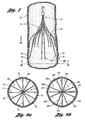
- Figure 3a is a side perspective view of one embodiment of the vena cava filter in an expanded state
- Figure 3b is a side view of the vena cava filter of Figure 3a in a collapsed state and disposed in an introducer tube;
- Figure 4 is an enlarged view of a portion of a second arcuate portion of a primary strut of the vena cava filter
- Figure 5 is a cross-sectional view of a hub of the filter in Figure 3 taken along line 5-5;
- Figure 6a is a cross-sectional view of the vena cava depicting the filter partially deployed leading with the removal hook;
- Figure 6b is a cross-sectional view of the vena cava depicting the filter partially deployed leading with the anchoring hooks;
- Figure 7 is a cross-sectional view of the vena cava in which the filter of Figure 3 has been deployed;
- Figure 8a is a cross-sectional view of the vena cava of Figure 7a taken along line 8-8;
- Figure 8b is a cross-sectional view of the vena cava of Figure 7a taken along line 8-8 depicting another embodiment of the filter;
- Figure 9a is a cross-sectional view of a blood vessel in which a retrieval sheath engages primary struts of the filter in Figure 3 for removal;
- Figure 9b is a cross-sectional view of a blood vessel in which the retrieval sheath includes the filter in the collapsed state for removal;
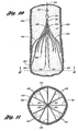
- Figure 10 is a cross-sectional view of a blood vessel showing a vena cava filter deployed within the blood vessel in accordance the invention.
- Figure 11 is a view of the blood vessel and filter of Figure 10 taken along the line 11-11.
- Figure 2 illustrates a vena cava filter 10 implanted in the vena cava 50 for the purpose of lysing or capturing thrombi carried by the blood flowing through the iliac veins 54,56 toward the heart and into the pulmonary arteries.
- the iliac veins merge at juncture 58 into the vena cava 50.
- the renal veins 60 from the kidneys 62 join the vena cava 50 downstream of juncture 58.
- the portion of the vena cava 50, between the juncture 58 and the renal veins 60, defines the inferior vena cava 52 in which the vena cava filter 10 has been percutaneously deployed through the femoral veins.
- the vena cava filter 10 has a length smaller than the length of the inferior vena cava 52. If the lower part of the filter extends into the iliac veins, filtering effectiveness will be compromised and if the filter wires cross over the origin of the renal veins the filter wires might interfere with the flow of blood from the kidneys.
- Figure 3a illustrates filter 10 in an expanded state and comprising four primary struts 12 each having first ends that emanate from a hub 11.
- Hub 11 attaches by crimping first ends.
- 14 of primary struts 12 together at a center point A in a compact bundle along a central or longitudinal axis X of the filter.
- the hub 11 has a minimal diameter for the size of wire used to form the struts.
- the primary struts 12 are formed from a superelastic material, stainless steel wire, Nitinol, cobalt-chromium-nickel-molybdenum-iron alloy, or cobalt chrome-alloy, or any other suitable material that will result in a self-opening or self-expanding filter.
- the primary struts 12 are preferably formed from wire having a round cross-section with a diameter of at least about 0,38 mm (0.015 inches).
- the primary struts 12 could take on any shape with rounded edges to maintain non-turbulent blood flow therethrough.
- Each, primary strut 12 includes an arcuate segment 16 having a soft S- shape.
- Each arcuate segment 16 is formed with a first curved portion 20 that is configured to softly bend away from the longitudinal or central axis X of the filter 10 and a second curved portion 23 that is configured to softly bend toward the longitudinal axis of the filter 10. Due to the soft bends of each arcuate segment 16, a prominence or a point of inflection on the primary strut 12 is substantially avoided to aid in non-traumatically engaging the vessel wall.
- the primary struts 12 terminate at anchoring hooks 26 that will anchor in the vessel wall when the filter 10 is deployed at a delivery location in the blood vessel.
- the primary struts 12 are configured to move between an expanded state for engaging the anchoring hooks 26 with the blood vessel and a collapsed state or configuration for filter retrieval or delivery.
- each arcuate segment 16 extends arcuately along a longitudinal axis X (as shown in Figure 3a ) and linearly relative to a radial axis R (as shown in Figure 8a ) from the first end 14 to the anchoring hook 26.
- the primary struts 12 radially extend from the first ends 14, defining the radial axis R.
- the primary struts 12 extend linearly relative to the radial axis R and avoid entanglement with other struts.
- each arcuate segment 16 allows each primary strut 12 to cross another primary strut 12 along the longitudinal axis X in the collapsed state such that each anchoring hook 26 faces the longitudinal axis X for filter retrieval or delivery.
- the anchoring hooks 26 engage the walls of the blood vessel to define a first axial portion to secure the filter in the blood vessel.
- the anchoring hooks 26 prevent the filter 10 from migrating from the delivery location in the blood vessel where it has been deposited.
- the primary struts 12 are shaped and dimensioned such that, when the filter 10 is freely expanded, the filter 10 has a diameter of between about 25 mm and 45 mm and a length of between about 3 cm and 7 cm.
- the filter 10 may have a diameter of about 35 mm and a length of about 5 cm.
- the primary struts 12 have sufficient spring strength that when the filter is deployed the anchoring hooks 26 will anchor into the vessel wall.
- the filter 10 includes a plurality of secondary struts 30 having connected ends 32 that also emanate from hub 11. Hub 11 attaches the connected ends 32 by crimping at the center point A of the secondary struts 30 together with the primary struts 12.
- each primary strut 12 has two secondary struts 30 in side-by-side relationship with the primary strut 12.
- the secondary struts 30 extend from the connected ends 32 to free ends 34 to centralize the filter 10 in the expanded state in the blood vessel.
- each secondary strut 30 extends arcuately along the longitudinal axis and linearly relative to the radial axis from the connected end 32 to the free end 34 for engaging the anchoring hooks 26 with the blood vessel.
- the secondary struts 30 extend linearly relative to the radial axis and avoid entanglement with other struts.
- the secondary struts 30 may be made from the same type of material as the primary struts 12. However, the secondary struts 30 may have a smaller diameter, e.g., at least about 0.3048mm (0.012 inches), than the primary struts 12.
- each of the secondary struts 30 is formed of a first arc 40 and a second arc 42.
- the first arc 40 extends from the connected end 32 away from the longitudinal axis X.
- the second arc 42 extends from the first arc 40 towards the longitudinal axis X.
- two secondary struts 30 are located on each side of one primary strut 12 to form a part of a netting configuration of the filter 10.
- the hub 11 is preferably made of the same material as the primary struts and secondary struts to minimize the possibility of galvanic corrosion or molecular changes in the material due to welding.
- free ends 34 of the secondary struts 30 When freely expanded, free ends 34 of the secondary struts 30 will expand radially outwardly to a diameter of about 25 mm to 45 mm to engage the vessel wall.
- the secondary struts 30 may expand radially outwardly to a diameter of between about 35 mm and 45 mm.
- the second arcs 42 of the free ends 34 engage the wall of a blood vessel to define a second axial portion where the vessel wall is engaged.
- the secondary struts 30 function to stabilize the position of the filter 10 about the center of the blood vessel in which it is deployed.
- the filter 10 has two layers or portions of struts longitudinally engaging the vessel wall of the blood vessel.
- the length of the filter 10 is preferably defined by the length of a primary strut 12.
- the diameter of the hub 11 is defined by the size of a bundle containing the primary struts 12 and secondary struts 30.
- the eight secondary struts 30 minimally add to the diameter of the hub 11 or the overall length of the filter 10, due to the reduced diameter of each secondary strut 30. This is accomplished while maintaining the filter 10 in a centered attitude relative to the vessel wall and formed as a part of the netting configuration of the filter 10.
- removal hook 46 extends from hub 11 opposite primary and secondary struts 12 and 30.
- each arcuate segment 16 has a thickness of at least about 0.381 mm (0.015 inch) and a tensile strength of between about 1965 005.8248kpa (285,000 pounds per square inch (psi)) and 2275269.9024kpa (330,000 psi).
- Each anchoring hook 26 is integral with the arcuate segment 16 and has the thickness and the tensile strength of the arcuate segment.
- Each secondary strut 30 has a thickness of at least about 0.3048mm (0.012 inch) and a tensile strength of between about 005.8248kpa (285,000 psi) and 2275269.9024kpa (330,000 psi).
- Figure 3b illustrates the filter 10 in a collapsed state disposed in a delivery/retrieval tube 94 for delivery or retrieval.
- the filter 10 is shaped for each primary strut 12 to cross another primary strut 12 along the longitudinal axis X.
- the anchoring hooks 26 are configured to invert or inwardly face the longitudinal axis X for retrieval and delivery of the filter 10. This inverted or inwardly facing configuration of the anchoring hooks 26 allows for simplified delivery and retrieval of filter 10.
- a concern that the anchoring hooks 26 may scrape, scratch, or tear the inner wall of a delivery/retrieval tube is eliminated, since the filter 10 of the present invention is shaped to have the anchoring hooks 26 face each other in the collapsed state.
- a set of inner and outer delivery/retrieval sheaths may be eliminated during the delivery or retrieval of the filter 10 through the jugular or femoral vein. Rather, merely one delivery/retrieval tube with a loop snare mechanism may be used to deliver or retrieve the filter 10 of the present invention.
- each primary strut 12 is configured to cross another primary strut 12 along the longitudinal axis X such that the arcuate segments 16, first curved portions 20 or second curved portions 23, occupy a first diameter D1.
- the first diameter is greater than a second diameter D2 occupied by the anchoring hooks 26 for filter retrieval or delivery. It has been found that the first diameter of the arcuate segments 16 serves to clear a path of retrieval, reducing radial force from the sheath or blood vessel on the anchoring hooks 26 during removal of the filter 10 from a patient. Reducing the radial force on the anchoring hooks 26 assists in preventing the anchoring hooks 26 from scraping, scratching, or tearing the inner wall of a sheath during removal of the filter 10 from a patient.
- the filter 10 may be delivered or retrieved by any suitable introducer (delivery or retrieval) tube.
- the introducer tube has an inside diameter of between about 4.5 French and 16 French, and more preferably between about 6.5 French and 14 French.
- the collapsed state of the filter may be defined by the inside diameter of an introducer tube.
- Figure 4 illustrates primary strut 12 including distal bend 43 formed thereon and extending outwardly radially from the longitudinal axis X.
- the distal bend 43 may extend outwardly at an angle between about 0.5 degree to 2 degrees, preferably 1.0 degree.
- the distal bend 43 allows the filter 10 to filter thrombi effectively at a smaller inside diameter of a blood vessel than otherwise would be possible while maintaining the ability to collapse for delivery or retrieval.
- Figure 5 illustrates a cross-sectional view of the filter 10 of Figure 3a at hub 11.
- the hub 11 houses a bundle of first ends 14 of the four primary struts 14 and connected ends 32 of secondary struts 30.
- Figure 5 further depicts the configurations of the primary and secondary struts 12 and 30.
- the primary struts 12 are spaced between two secondary struts 30.
- the primary struts 12 may be spaced between any other suitably desired number of secondary struts 30.
- Figures 6a and 6b both illustrate the filter 10 partially deployed .in inferior vena cava 52.
- Figure 6a shows the filter 10 being delivered by a delivery tube 48 through the femoral vein of a patient
- Figure 6b shows the filter 10 being delivered by a delivery tube 50 through the jugular vein of a patient.
- a delivery tube is percutaneously inserted through the patient's vessel such that the distal end of the delivery tube is at the location of deployment.
- a wire guide is preferably used to guide the delivery tube to the location of deployment.
- the filter 10 is inserted through the proximal end of the delivery tube 48 with the removal hook 46 leading and anchoring hooks 26 of the primary struts 12 held by a filter retainer member for delivery via the femoral vein of a patient.
- the filter 10 is inserted through the proximal end of the delivery tube 50 with the anchoring hooks 26 of the primary struts 12 leading and the removal hook 46 trailing for delivery via the jugular vein of a patient.
- a pusher wire having a pusher member at its distal end may be fed through the proximal end of the delivery tube 50 thereby pushing the filter 10 until the filter 10 reaches the distal end of the delivery tube 50 to a desired location.
- the secondary struts 30 expand first to centralize or balance the filter within the vessel.
- the secondary struts 30 expand to an expanded position as shown in both Figures 6a and 6b .
- the second arcs 42 engage the inner wall of the vessel.
- the second arcs 42 of the secondary struts 30 function to stabilize the attitude of filter 10 about the center of the blood vessel.
- the anchoring hooks 26 of the primary struts 12 and the second arcs 42 of the secondary struts 30 are in engagement with the vessel wall.
- the anchoring hooks 26 of the primary struts 12 have anchored the filter 10 at the location of deployment in the vessel, preventing the filter 10 from moving with the blood flow through the vessel.
- the filter 10 is supported by two sets of struts that are spaced axially along the length of the filter.
- FIG 7 illustrates the filter 10 fully expanded after being deployed in inferior vena cava 52.
- the inferior vena cava 52 has been broken away so that the filter 10 can be seen.
- the direction of the blood flow BF is indicated in Figure 7 by the arrow that is labeled BF.
- the anchoring hooks 26 at the ends of the primary struts 12 are shown as being anchored in the inner lining of the inferior vena cava 52.
- the anchoring hooks 26 include barbs 29 that, in one embodiment, project toward the hub 11 of the filter. The barbs 29 function to retain the filter 10 in the location of deployment.
- the spring biased configuration of the primary struts 12 further causes the anchoring hooks 26 to engage the vessel wall and anchor the filter at the location of deployment. After initial deployment, the pressure of the blood flow on the filter 10 contributes in maintaining the barbs 29 anchored in the inner lining of the inferior vena cava 52. As seen in Figure 7 , the second arcs 42 of secondary struts 30 also have a spring biased configuration to engage with the vessel wall.
- the hub 11 and removal hook 46 are positioned downstream from the location at which the anchoring hooks 26 are anchored in the vessel. When captured by the struts 12 and 30, thrombi remains lodged in the filter. The filter 10 along with the thrombi may then be percutaneously removed from the vena cava. When the filter 10 is to be removed, the removal hook 46 is preferably grasped by a retrieval instrument that is percutaneously introduced in the vena cava in the direction of removal hook 16 first.
- Figure 8a depicts a netting configuration or pattern formed by the primary struts 12, secondary struts 30, and the hub 11 relative to radial axis R.
- the netting pattern shown in Figure 8a functions to catch thrombi carried in the blood stream prior to reaching the heart and lungs to prevent the possibility of a pulmonary embolism.
- the netting pattern is sized to catch and stop thrombi that are of a size that are undesirable to be carried in the vasculature of the patient. Due to its compacted size, the hub minimally resists blood flow.
- Figure 8a depicts the netting pattern including primary struts and secondary struts at substantially equal angular space relative to each other.
- the netting pattern provides an even distribution between the primary and secondary struts to the blood flow, increasing the likelihood of capturing thrombi.
- each of the sets of primary struts 312 and secondary struts 330 may be independently spaced substantially equally at their respective portions relative to radial axis R'.
- the secondary struts 330 may be spaced equally relative to the other secondary struts 330 and the primary struts 312 may be spaced equally relative to the other primary struts 312.
- the netting pattern in this embodiment shown by the cross-sectional view of the vena cava (taken along line 8-8) will have uneven or unequal spacing between the primary struts 312 and secondary struts 330.
- Figure 9a illustrates part of a retrieval device 65 being used in a procedure for removing the filter 10 from the inferior vena cava 52.
- the retrieval device 65 is percutaneously introduced into the superior vena cava via the jugular vein.
- a removal catheter or sheath 68 of the retrieval device 65 is inserted into the superior vena cava.
- a wire 70 having a loop snare 72 at its distal end is threaded through the removal sheath 68 and is exited through the distal end of the sheath 68.
- the wire 70 is then manipulated by any suitable means from the proximal end of the retrieval device such that the loop snare 72 captures the removal hook 46 of the filter 10.
- the sheath 68 is passed over the filter 10.
- the primary struts 12 and then the secondary struts 30 engage the edge of the sheath 68 and are caused to pivot or undergo bend deflection at the hub 11 toward the longitudinal axis of the filter.
- the pivoting toward the longitudinal axis causes the ends of the struts 12 and 30 to be retracted from the vessel wall. In this way, only surface lesions 74 and small point lesions 76 on the vessel wall are created in the removal procedure.
- the surface lesions 74 are created by the ends of the secondary struts 30 and the small point legions 76 are created by the anchoring hooks 26 of the primary struts 12.
- any other suitable procedure may be implemented to remove the filter from the patient.
- this device has been disclosed as preferably being constructed from wire having a round cross section, it could also be cut from a tube of suitable material by laser cutting, electrical discharge machining or any other suitable process.
- the primary and secondary struts can be formed from any suitable material that will result in a self-opening or self-expanding filter, such as shape memory alloys.
- Shape memory alloys have the desirable property of becoming rigid, that is, returning to a remembered state, when heated above a transition temperature.
- a shape memory alloy suitable for the present invention is Ni-Ti available under the more commonly known name Nitinol. When this material is heated above the transition temperature, the material undergoes a phase transformation from martensite to austenic, such that material returns to its remembered state.
- the transition temperature is dependent on the relative proportions of the alloying elements Ni and Ti and the optional inclusion of alloying additives.
- both the primary struts and the secondary struts are made from Nitinol with a transition temperature that is slightly below normal body temperature of humans, which is about 37°C (98.6°F).
- the alloy of the struts will transform to austenite, that is, the remembered state, which for the present invention is an expanded configuration when the filter is deployed in the blood vessel.
- the filter is cooled to transform the material to martensite which is more ductile than austenite, making the struts more malleable. As such, the filter can be more easily collapsed and pulled into the sheath for removal.
- both the primary struts and the secondary struts are made from Nitinol with a transition temperature that is above normal body temperature of humans, which is about 37°C (98.6°F).
- the struts are in the martensitic state so that the struts are sufficiently ductile to bend or form into a desired shape, which for the present invention is an expanded configuration.
- the filter is heated to transform the alloy to austenite so that the filter becomes rigid and returns to a remembered state, which for the filter is a collapsed configuration.
- a filter 420 includes four primary struts 438 and eight secondary struts 440 that extend from a hub 442. Each primary strut 438 terminates in an anchoring hook 452 with a barb 454.
- the primary struts 438 have sufficient spring strength such that when the filter is deployed in a vena cava 436, the anchoring hooks 452, in particular, the barbs 444, anchor into the vessel wall of the vena cava 436 to prevent the filter 420 from migrating from the delivery location.
- the pressure of the blood flow on the filter 420 contributes in maintaining the barbs 454 anchored in the inner lining of the vena cava 436.
- a pair of secondary struts 440 are positioned between adjacent primary struts 438.
- Each secondary strut 440 extends from the hub 442 and terminates in a tip 462 pointing toward the central axis 444.
- the tips 462 are located longitudinally between the hub 442 and the anchoring hooks 454 of the primary struts 438.
- the connected ends of each pair of secondary struts 440 positioned between adjacent primary struts are twisted together, defining a twisted section 464.
- the twisted sections 464 effectively stiffens each pair of secondary struts 440, thinner secondary struts may be used to provide the appropriate balancing forces to center the filter in the blood vessel. Moreover, an additional benefit of the twisted section is that they prevent the secondary struts from entangling with the primary struts.
- the secondary struts 440 can be made from the same type of material as the primary struts 438 and can be formed by the same process used to form the primary struts. However, the secondary struts may have a smaller diameter than the primary struts.
- each pair of secondary struts 440 positioned between adjacent primary struts 438 can be twisted about each other after the struts have been attached to the hub 442.
- Each twisted section 464 includes one or more twists.
- each twisted section 464 may include up to about ten twists. In certain implementations, the number of twists in each section 464 may be between about three to five twists. Increasing the number of twists increases the stiffness of the pair of secondary struts twisted about each other.
- the hub 442 is preferably made of the same material as the primary struts and secondary struts to minimize the possibility of galvanic corrosion.
- Figure 11 illustrates a netting pattern ("net") formed by the primary struts 438, the secondary struts 440, and the hub 442.
- This net functions to catch thrombi carried in the blood stream to prevent the thrombi from reaching the heart and lungs, where the thrombi could cause pulmonary embolism.
- the net is sized to catch and stop thrombi that are of a size that are undesirable in the vasculature of the patient.
- the struts 438 have substantially equal angular spacing between the struts.
- the hub 442 and a removal hook 466 attached to the hub are located downstream of the location at which the anchoring hooks 452 are anchored in the vessel 436.
- thrombi When captured by the struts, thrombi remain lodged in the filter 420.
- the filter 420 along with the thrombi may then be removed percutaneously from the vena cava.
- the removal hook 466 is typically grasped by the retrieval hook that is introduced in the vena cava percutaneously.
Claims (11)
- Filtre amovible (420) pour retenir les caillots thrombolytiques dans un vaisseau sanguin, le filtre comportant :une pluralité de bras primaires (438) munis de premières extrémités attachées ensemble le long d'un axe longitudinal, chaque bras primaire étant muni d'un segment incurvé s'entendant depuis la première extrémité jusqu'à un crochet de fixation (452), les bras primaires étant configurés pour se déplacer entre un état déployé pour engager les crochets de fixation avec le vaisseau sanguin et un état affaissé pour l'enlèvement ou la pose du filtre ; chaque bras primaire étant configuré pour croiser un autre bras primaire le long de l'axe longitudinal dans l'état affaissé de sorte que les segments incurvés occupent un premier diamètre supérieur à un deuxième diamètre occupé par les crochets de fixation dans l'état affaisé pour l'enlèvement ou la pose du filtre, dans lequel des paires de bras secondaires (440) sont positionnées entre les paires de bras primaires, chaque paire de bras secondaires étant torsadée les unes autour des autres près des extrémités reliées des bras secondaires respectifs pour former une section torsadée (464).
- Filtre amovible selon la revendication 1, ladite pluralité de bras secondaires présentant des extrémités reliées attachées ensemble le long de l'axe longitudinal et s'étendant à partir de là jusqu'aux extrémités libres pour centrer le filtre dans l'état déployé dans le vaisseau sanguin, comportant en outre :un embout configuré pour loger axialement les premières extrémités de la pluralité de bras primaires ; etun crochet de retrait s'étendant depuis l'embout à l'opposé de la pluralité de bras primaires pour l'enlèvement du filtre du vaisseau sanguin.
- Filtre amovible selon la revendication 1 dans lequel le segment incurvé comprend une première portion courbe et une deuxième portion courbe, la première portion courbe s'étendant depuis la première extrémité, la deuxième portion courbe s'étendant depuis la première portion courbe et se terminant au crochet de fixation.
- Filtre amovible selon la revendication 3 dans lequel la première portion courbe est configurée pour s'étendre radialement depuis l'axe longitudinal du filtre et la deuxième portion courbe est configurée pour s'étendre radialement vers l'axe longitudinal du filtre.
- Filtre amovible selon la revendication 1 dans lequel chaque bras primaire est formé dans un matériau super-élastique, un fil d'acier inoxydable, du nitinol, un alliage cobalt-chrome-nickel-molybdène-fer, ou un alliage cobalt-chrome.
- Filtre amovible selon la revendication 1 dans lequel chaque bras secondaire est formé dans un matériau super-élastique, un fil d'acier inoxydable, du nitinol, un alliage cobalt-chrome-nickel-molybdène-fer, ou un alliage cobalt-chrome.
- Filtre amovible selon la revendication 2 dans lequel le premier diamètre se situe entre environ 6 et 14 French, et le deuxième diamètre se situe entre environ 3 et 9 French.
- Filtre amovible selon la revendication 1 dans lequel les bras sont formés dans un alliage à mémoire de forme avec une température de transition.
- Filtre amovible selon la revendication 8 dans lequel les bras s'affaissent jusqu'à l'état affaissé lorsque la température des bras est environ égale ou supérieure à la température de transition.
- Filtre amovible selon la revendication 8 dans lequel les bras se déploient jusqu'à l'état déployé lorsque la température des bras est environ égale ou supérieure à la température de transition.
- Filtre selon la revendication 1 dans lequel chaque section torsadée comprend environ une à dix torsades.
Applications Claiming Priority (5)
| Application Number | Priority Date | Filing Date | Title |
|---|---|---|---|
| US56294304P | 2004-04-16 | 2004-04-16 | |
| US56281304P | 2004-04-16 | 2004-04-16 | |
| US56290904P | 2004-04-16 | 2004-04-16 | |
| US56317604P | 2004-04-16 | 2004-04-16 | |
| PCT/US2005/013158 WO2005102210A1 (fr) | 2004-04-16 | 2005-04-18 | Filtre a veine profonde retirable pour traumatisme reduit selon une configuration affaissee |
Publications (2)
| Publication Number | Publication Date |
|---|---|
| EP1737382A1 EP1737382A1 (fr) | 2007-01-03 |
| EP1737382B1 true EP1737382B1 (fr) | 2011-03-30 |
Family
ID=34966414
Family Applications (1)
| Application Number | Title | Priority Date | Filing Date |
|---|---|---|---|
| EP05737036A Active EP1737382B1 (fr) | 2004-04-16 | 2005-04-18 | Filtre a veine profonde retirable pour traumatisme reduit selon une configuration affaissee |
Country Status (8)
| Country | Link |
|---|---|
| US (2) | US7699867B2 (fr) |
| EP (1) | EP1737382B1 (fr) |
| JP (1) | JP4918636B2 (fr) |
| AT (1) | ATE503438T1 (fr) |
| AU (1) | AU2005235301B2 (fr) |
| CA (1) | CA2562688A1 (fr) |
| DE (1) | DE602005027189D1 (fr) |
| WO (1) | WO2005102210A1 (fr) |
Families Citing this family (42)
| Publication number | Priority date | Publication date | Assignee | Title |
|---|---|---|---|---|
| US7314477B1 (en) | 1998-09-25 | 2008-01-01 | C.R. Bard Inc. | Removable embolus blood clot filter and filter delivery unit |
| US9204956B2 (en) | 2002-02-20 | 2015-12-08 | C. R. Bard, Inc. | IVC filter with translating hooks |
| US7976562B2 (en) | 2004-01-22 | 2011-07-12 | Rex Medical, L.P. | Method of removing a vein filter |
| DK1737383T3 (en) | 2004-04-16 | 2015-01-12 | Cook Medical Technologies Llc | Removable VENA CAVA FILTER by bearers FOR IMPROVED COLLECTION AND FEED |
| DK1737384T3 (da) | 2004-04-16 | 2010-03-08 | Cook Inc | Udtageligt vena cava-filter med indad rettede forankringskroge i sammenklappet tilstand |
| AU2005235301B2 (en) | 2004-04-16 | 2010-07-22 | Cook, Inc. | Removable vena cava filter for reduced trauma in collapsed configuration |
| US7625390B2 (en) * | 2004-04-16 | 2009-12-01 | Cook Incorporated | Removable vena cava filter |
| JP4898986B2 (ja) | 2004-04-16 | 2012-03-21 | クック メディカル テクノロジーズ エルエルシー | 損傷を減少させるためのアンカー形状を有する取出し可能な大静脈フィルタ |
| US7704267B2 (en) | 2004-08-04 | 2010-04-27 | C. R. Bard, Inc. | Non-entangling vena cava filter |
| JP2008514293A (ja) | 2004-09-27 | 2008-05-08 | クック インコーポレイテッド | 軸線方向の曲りを有する支柱を備えた取り出し可能な大静脈フィルタ |
| EP1814488A1 (fr) * | 2004-11-08 | 2007-08-08 | Cook Incorporated | Filtre de caillot sanguin concu pour un fil-guide |
| CA2946470C (fr) * | 2005-05-12 | 2019-02-19 | C.R. Bard Inc. | Filtre amovible pour caillot sanguin ou embole |
| JP4851522B2 (ja) | 2005-08-09 | 2012-01-11 | シー・アール・バード・インコーポレーテッド | 挿入型血栓フィルタ及びデリバリシステム |
| JP2009519731A (ja) | 2005-11-18 | 2009-05-21 | シー・アール・バード・インコーポレイテツド | フィラメントを有する大静脈フィルタ |
| CA2633848A1 (fr) * | 2005-12-30 | 2007-07-12 | C.R. Bard Inc. | Filtre pour caillots sanguin active apres implantation |
| US10188496B2 (en) | 2006-05-02 | 2019-01-29 | C. R. Bard, Inc. | Vena cava filter formed from a sheet |
| WO2007143602A2 (fr) | 2006-06-05 | 2007-12-13 | C.R. Bard Inc. | Filtre pour caillots sanguins générateurs d'embolie utilisable avec un système de mise en place unique ou un système de retrait unique via un accès fémoral ou jugulaire |
| US10105206B2 (en) | 2006-12-19 | 2018-10-23 | C.R. Bard, Inc. | Inferior vena cava filter with stability features |
| US8795351B2 (en) | 2007-04-13 | 2014-08-05 | C.R. Bard, Inc. | Migration resistant embolic filter |
| US8062328B2 (en) | 2007-09-07 | 2011-11-22 | Merit Medical Systems, Inc. | Percutaneous permanent retrievable vascular filter |
| US8795318B2 (en) * | 2007-09-07 | 2014-08-05 | Merit Medical Systems, Inc. | Percutaneous retrievable vascular filter |
| US8246672B2 (en) | 2007-12-27 | 2012-08-21 | Cook Medical Technologies Llc | Endovascular graft with separately positionable and removable frame units |
| US8114116B2 (en) | 2008-01-18 | 2012-02-14 | Cook Medical Technologies Llc | Introduction catheter set for a self-expandable implant |
| US8246648B2 (en) | 2008-11-10 | 2012-08-21 | Cook Medical Technologies Llc | Removable vena cava filter with improved leg |
| WO2011014703A1 (fr) | 2009-07-29 | 2011-02-03 | C.R. Bard, Inc. | Filtre tubulaire |
| US9308066B2 (en) * | 2010-01-12 | 2016-04-12 | Cook Medical Technologies Llc | Visual stabilizer on anchor legs of vena cava filter |
| US10022212B2 (en) | 2011-01-13 | 2018-07-17 | Cook Medical Technologies Llc | Temporary venous filter with anti-coagulant delivery method |
| CA2828480C (fr) | 2011-02-28 | 2019-05-07 | Adient Medical, Inc. | Filtre vasculaire absorbable |
| US20120221040A1 (en) | 2011-02-28 | 2012-08-30 | Mitchell Donn Eggers | Absorbable Vascular Filter |
| US10531942B2 (en) | 2011-02-28 | 2020-01-14 | Adient Medical, Inc. | Absorbable vascular filter |
| US8734480B2 (en) | 2011-08-05 | 2014-05-27 | Merit Medical Systems, Inc. | Vascular filter |
| US8740931B2 (en) | 2011-08-05 | 2014-06-03 | Merit Medical Systems, Inc. | Vascular filter |
| US8702747B2 (en) | 2011-10-21 | 2014-04-22 | Cook Medical Technologies Llc | Femoral removal vena cava filter |
| EP2816969B1 (fr) | 2012-02-23 | 2018-06-13 | Merit Medical Systems, Inc. | Filtre vasculaire |
| WO2014099247A1 (fr) | 2012-12-19 | 2014-06-26 | Muffin Incorporated | Appareil et procédé pour le placement d'un filtre intravasculaire |
| WO2014099244A1 (fr) | 2012-12-19 | 2014-06-26 | Muffin Incorporated | Appareil et procédé de récupération d'un filtre intravasculaire |
| WO2015021296A1 (fr) | 2013-08-09 | 2015-02-12 | Merit Medical Systems, Inc. | Systèmes et méthodes de délivrance de filtre vasculaire |
| US10010398B2 (en) | 2013-10-01 | 2018-07-03 | Cook Medical Technologies Llc | Filter device, system, and method |
| GB2524289B (en) * | 2014-03-19 | 2016-03-09 | Cook Medical Technologies Llc | Vascular filter |
| JP6785106B2 (ja) * | 2016-09-27 | 2020-11-18 | テルモ株式会社 | 医療システム |
| US11051928B2 (en) * | 2019-04-11 | 2021-07-06 | Neuravi Limited | Floating carotid filter |
| CN115607331B (zh) * | 2022-12-16 | 2023-03-31 | 北京心祐医疗科技有限公司 | 可调锚定式腔静脉滤器 |
Family Cites Families (218)
| Publication number | Priority date | Publication date | Assignee | Title |
|---|---|---|---|---|
| US583887A (en) * | 1897-06-08 | Automatic wagon-brake | ||
| US2281448A (en) | 1941-09-17 | 1942-04-28 | Scully Signal Co | Device for partially obstructing pipes |
| US3174851A (en) | 1961-12-01 | 1965-03-23 | William J Buehler | Nickel-base alloys |
| US3137298A (en) | 1963-06-25 | 1964-06-16 | Jacob A Glassman | Surgical extractors |
| US3436120A (en) * | 1964-08-13 | 1969-04-01 | J J Grady Co Inc | Blast furnace teardown apparatus |
| US3334629A (en) | 1964-11-09 | 1967-08-08 | Bertram D Cohn | Occlusive device for inferior vena cava |
| US3540431A (en) | 1968-04-04 | 1970-11-17 | Kazi Mobin Uddin | Collapsible filter for fluid flowing in closed passageway |
| US3868956A (en) | 1972-06-05 | 1975-03-04 | Ralph J Alfidi | Vessel implantable appliance and method of implanting it |
| US3952747A (en) | 1974-03-28 | 1976-04-27 | Kimmell Jr Garman O | Filter and filter insertion instrument |
| SU835447A1 (ru) | 1979-05-16 | 1981-06-07 | Предприятие П/Я А-1882 | Имплантируемый венозный фильтр |
| SU955912A1 (ru) | 1981-03-12 | 1988-02-23 | Радиотехнический Институт Ан Ссср | Способ профилактики тромбоэмболии легочной артерии и интравенозный фильтр дл его осуществлени |
| US4425908A (en) * | 1981-10-22 | 1984-01-17 | Beth Israel Hospital | Blood clot filter |
| SU1103868A1 (ru) | 1982-02-03 | 1984-07-23 | Киргизский государственный медицинский институт | Противоэмболический фильтр |
| SE445884B (sv) | 1982-04-30 | 1986-07-28 | Medinvent Sa | Anordning for implantation av en rorformig protes |
| US4643184A (en) | 1982-09-29 | 1987-02-17 | Mobin Uddin Kazi | Embolus trap |
| US4494531A (en) | 1982-12-06 | 1985-01-22 | Cook, Incorporated | Expandable blood clot filter |
| US5067957A (en) | 1983-10-14 | 1991-11-26 | Raychem Corporation | Method of inserting medical devices incorporating SIM alloy elements |
| US4665906A (en) | 1983-10-14 | 1987-05-19 | Raychem Corporation | Medical devices incorporating sim alloy elements |
| US5190546A (en) | 1983-10-14 | 1993-03-02 | Raychem Corporation | Medical devices incorporating SIM alloy elements |
| US6221102B1 (en) | 1983-12-09 | 2001-04-24 | Endovascular Technologies, Inc. | Intraluminal grafting system |
| US4727873A (en) | 1984-04-17 | 1988-03-01 | Mobin Uddin Kazi | Embolus trap |
| US4759757A (en) | 1984-04-18 | 1988-07-26 | Corvita Corporation | Cardiovascular graft and method of forming same |
| DE3429850A1 (de) | 1984-05-12 | 1986-02-20 | Ing. Walter Hengst GmbH & Co KG, 4400 Münster | Verbesserter, in adern einsetzbarer blutfilter |
| DK151404C (da) | 1984-05-23 | 1988-07-18 | Cook Europ Aps William | Sammenklappeligt filter til implantation i en patients blodkar |
| US5037377A (en) | 1984-11-28 | 1991-08-06 | Medtronic, Inc. | Means for improving biocompatibility of implants, particularly of vascular grafts |
| FR2573646B1 (fr) | 1984-11-29 | 1988-11-25 | Celsa Composants Electr Sa | Filtre perfectionne, en particulier pour la retenue de caillots sanguins |
| KR900000592B1 (ko) * | 1985-02-16 | 1990-02-01 | 미쓰비시지도오샤고오교오 가부시기가이샤 | 자동변속장치의 변속제어장치 |
| FR2587901A1 (en) | 1985-09-27 | 1987-04-03 | Bocquee Henry | Device intended to stop the circulation of thrombi in vessels |
| SE453258B (sv) | 1986-04-21 | 1988-01-25 | Medinvent Sa | Elastisk, sjelvexpanderande protes samt forfarande for dess framstellning |
| US4793348A (en) | 1986-11-15 | 1988-12-27 | Palmaz Julio C | Balloon expandable vena cava filter to prevent migration of lower extremity venous clots into the pulmonary circulation |
| FR2606641B1 (fr) | 1986-11-17 | 1991-07-12 | Promed | Dispositif filtrant pour caillots sanguins |
| GB2200848B (en) | 1987-02-25 | 1991-02-13 | Mo Med Inst Pirogova | Intravenous filter, and apparatus and method for preoperative preparation thereof |
| US4817600A (en) * | 1987-05-22 | 1989-04-04 | Medi-Tech, Inc. | Implantable filter |
| US4873978A (en) | 1987-12-04 | 1989-10-17 | Robert Ginsburg | Device and method for emboli retrieval |
| FR2632864B2 (fr) | 1987-12-31 | 1990-10-19 | Biomat Sarl | Systeme filtrant elastique anti-embolique pour veine cave et ensemble de moyens pour sa mise en place |
| SU1711906A1 (ru) | 1988-01-11 | 1992-02-15 | 2-й Московский государственный медицинский институт им.Н.И.Пирогова | Интравенозный фильтр и устройство дл его имплантации |
| US4830003A (en) | 1988-06-17 | 1989-05-16 | Wolff Rodney G | Compressive stent and delivery system |
| FR2632848A1 (fr) | 1988-06-21 | 1989-12-22 | Lefebvre Jean Marie | Filtre a usage medical |
| US4832055A (en) | 1988-07-08 | 1989-05-23 | Palestrant Aubrey M | Mechanically locking blood clot filter |
| US4950227A (en) | 1988-11-07 | 1990-08-21 | Boston Scientific Corporation | Stent delivery system |
| US4856516A (en) | 1989-01-09 | 1989-08-15 | Cordis Corporation | Endovascular stent apparatus and method |
| US5152777A (en) | 1989-01-25 | 1992-10-06 | Uresil Corporation | Device and method for providing protection from emboli and preventing occulsion of blood vessels |
| US4969891A (en) | 1989-03-06 | 1990-11-13 | Gewertz Bruce L | Removable vascular filter |
| FR2649884B1 (fr) | 1989-07-18 | 1993-04-30 | Ems Ind | Filtre pour la retenue de caillots sanguins |
| US5242462A (en) | 1989-09-07 | 1993-09-07 | Boston Scientific Corp. | Percutaneous anti-migration vena cava filter |
| US5059205A (en) | 1989-09-07 | 1991-10-22 | Boston Scientific Corporation | Percutaneous anti-migration vena cava filter |
| GB2238485B (en) | 1989-11-28 | 1993-07-14 | Cook William Europ | A collapsible filter for introduction in a blood vessel of a patient |
| FR2655533A1 (fr) | 1989-12-13 | 1991-06-14 | Lefebvre Jean Marie | Filtre-catheter. |
| US5421832A (en) | 1989-12-13 | 1995-06-06 | Lefebvre; Jean-Marie | Filter-catheter and method of manufacturing same |
| US5304121A (en) | 1990-12-28 | 1994-04-19 | Boston Scientific Corporation | Drug delivery system making use of a hydrogel polymer coating |
| US5135516A (en) | 1989-12-15 | 1992-08-04 | Boston Scientific Corporation | Lubricious antithrombogenic catheters, guidewires and coatings |
| FR2657261A1 (fr) | 1990-01-19 | 1991-07-26 | Bovyn Gilles | Dispositif d'implantation temporaire d'un filtre sanguin dans une veine du corps humain. |
| FR2660189B1 (fr) | 1990-03-28 | 1992-07-31 | Lefebvre Jean Marie | Dispositif destine a etre implante dans un vaisseau avec des pattes laterales a dents antagonistes. |
| US5071407A (en) | 1990-04-12 | 1991-12-10 | Schneider (U.S.A.) Inc. | Radially expandable fixation member |
| US5221261A (en) | 1990-04-12 | 1993-06-22 | Schneider (Usa) Inc. | Radially expandable fixation member |
| FR2663217B1 (fr) | 1990-06-15 | 1992-10-16 | Antheor | Dispositif filtrant destine a la prevention des embolies. |
| CA2048307C (fr) | 1990-08-14 | 1998-08-18 | Rolf Gunther | Methode et appareil pour filtrer le sang dans un vaisseau sanguin |
| US5108419A (en) | 1990-08-16 | 1992-04-28 | Evi Corporation | Endovascular filter and method for use thereof |
| US5160342A (en) | 1990-08-16 | 1992-11-03 | Evi Corp. | Endovascular filter and method for use thereof |
| US5147379A (en) | 1990-11-26 | 1992-09-15 | Louisiana State University And Agricultural And Mechanical College | Insertion instrument for vena cava filter |
| FR2672487B1 (fr) | 1991-02-12 | 1998-09-11 | Guy Caburol | Filtre veineux autocentrant modulable implantable sur le trajet sanguin. |
| DE69222156T2 (de) | 1991-03-14 | 1998-04-02 | Ethnor | Lungenemboliefilter sowie Bausatz zum Präsentieren und Einsetzen desselben |
| US5350398A (en) | 1991-05-13 | 1994-09-27 | Dusan Pavcnik | Self-expanding filter for percutaneous insertion |
| US5304200A (en) | 1991-05-29 | 1994-04-19 | Cordis Corporation | Welded radially expandable endoprosthesis and the like |
| US5217484A (en) | 1991-06-07 | 1993-06-08 | Marks Michael P | Retractable-wire catheter device and method |
| US5649906A (en) | 1991-07-17 | 1997-07-22 | Gory; Pierre | Method for implanting a removable medical apparatus in a human body |
| US5626605A (en) | 1991-12-30 | 1997-05-06 | Scimed Life Systems, Inc. | Thrombosis filter |
| US5405377A (en) | 1992-02-21 | 1995-04-11 | Endotech Ltd. | Intraluminal stent |
| FR2689388B1 (fr) | 1992-04-07 | 1999-07-16 | Celsa Lg | Filtre sanguin perfectionne eventuellement resorbable. |
| US5540712A (en) | 1992-05-01 | 1996-07-30 | Nitinol Medical Technologies, Inc. | Stent and method and apparatus for forming and delivering the same |
| US5224953A (en) | 1992-05-01 | 1993-07-06 | The Beth Israel Hospital Association | Method for treatment of obstructive portions of urinary passageways |
| US5324304A (en) * | 1992-06-18 | 1994-06-28 | William Cook Europe A/S | Introduction catheter set for a collapsible self-expandable implant |
| FR2694491B1 (fr) | 1992-08-07 | 1994-09-30 | Celsa Lg | Filtres à pattes triangulées. |
| US5382261A (en) | 1992-09-01 | 1995-01-17 | Expandable Grafts Partnership | Method and apparatus for occluding vessels |
| US5527338A (en) | 1992-09-02 | 1996-06-18 | Board Of Regents, The University Of Texas System | Intravascular device |
| FR2696092B1 (fr) | 1992-09-28 | 1994-12-30 | Lefebvre Jean Marie | Kit à usage médical composé d'un filtre et de son dispositif de mise en place dans le vaisseau. |
| FR2699809B1 (fr) | 1992-12-28 | 1995-02-17 | Celsa Lg | Dispositif pouvant constituer sélectivement un filtre sanguin temporaire. |
| US5843167A (en) | 1993-04-22 | 1998-12-01 | C. R. Bard, Inc. | Method and apparatus for recapture of hooked endoprosthesis |
| DE69433064T2 (de) | 1993-10-01 | 2004-06-17 | Boston Scientific Corp., Natick | Vena-cava-filter |
| FR2710833B1 (fr) | 1993-10-05 | 1995-11-24 | Celsa Lg | Dispositif d'implantation d'une prothèse médicale dans un conduit d'un corps humain ou animal et procédé de centrage d'un tel dispositif. |
| US5437282A (en) | 1993-10-29 | 1995-08-01 | Boston Scientific Corporation | Drive shaft for acoustic imaging catheters and flexible catheters |
| FR2714814B1 (fr) | 1994-01-10 | 1996-03-29 | Bentex Trading Sa | Dispositif destiné à être placé dans un vaisseau avec des pattes de fixation aplaties. |
| US5549629A (en) | 1994-03-10 | 1996-08-27 | Thomas; Stacy I. | Apparatus for covering a surgical needle to protect the user |
| WO1995027448A1 (fr) | 1994-04-06 | 1995-10-19 | William Cook Europe A/S | Dispositif medical destine a etre implante dans le systeme vasculaire d'un patient |
| US5853420A (en) | 1994-04-21 | 1998-12-29 | B. Braun Celsa | Assembly comprising a blood filter for temporary or definitive use and device for implanting it, corresponding filter and method of implanting such a filter |
| US5634942A (en) | 1994-04-21 | 1997-06-03 | B. Braun Celsa | Assembly comprising a blood filter for temporary or definitive use and a device for implanting it |
| US5476508A (en) | 1994-05-26 | 1995-12-19 | Tfx Medical | Stent with mutually interlocking filaments |
| DE9409484U1 (de) | 1994-06-11 | 1994-08-04 | Naderlinger Eduard | Vena-cava Thromben-Filter |
| US6123715A (en) | 1994-07-08 | 2000-09-26 | Amplatz; Curtis | Method of forming medical devices; intravascular occlusion devices |
| ES2340142T3 (es) | 1994-07-08 | 2010-05-31 | Ev3 Inc. | Sistema para llevar a cabo un procedimiento intravascular. |
| AU708360B2 (en) * | 1994-09-15 | 1999-08-05 | C.R. Bard Inc. | Hooked endoprosthesis |
| US5601595A (en) | 1994-10-25 | 1997-02-11 | Scimed Life Systems, Inc. | Remobable thrombus filter |
| US5709704A (en) | 1994-11-30 | 1998-01-20 | Boston Scientific Corporation | Blood clot filtering |
| US6013093A (en) | 1995-11-28 | 2000-01-11 | Boston Scientific Corporation | Blood clot filtering |
| US5549626A (en) | 1994-12-23 | 1996-08-27 | New York Society For The Ruptured And Crippled Maintaining The Hospital For Special Surgery | Vena caval filter |
| DE69629865T2 (de) | 1995-04-14 | 2004-07-15 | B. Braun Medical Sas | Intraluminale medische Vorrichtung, insbesondere Blutfilter |
| US5807398A (en) | 1995-04-28 | 1998-09-15 | Shaknovich; Alexander | Shuttle stent delivery catheter |
| US5681347A (en) | 1995-05-23 | 1997-10-28 | Boston Scientific Corporation | Vena cava filter delivery system |
| US20020193828A1 (en) | 2001-06-14 | 2002-12-19 | Cook Incorporated | Endovascular filter |
| FR2737654B1 (fr) | 1995-08-10 | 1997-11-21 | Braun Celsa Sa | Unite de filtration pour la retenue de caillots sanguins |
| US6287315B1 (en) | 1995-10-30 | 2001-09-11 | World Medical Manufacturing Corporation | Apparatus for delivering an endoluminal prosthesis |
| BE1009746A3 (fr) | 1995-11-07 | 1997-07-01 | Dereume Jean Pierre Georges Em | Dispositif de capture a introduire dans une cavite d'un corps humain ou animal. |
| US5695519A (en) | 1995-11-30 | 1997-12-09 | American Biomed, Inc. | Percutaneous filter for carotid angioplasty |
| NL1002423C2 (nl) | 1996-02-22 | 1997-08-25 | Cordis Europ | Tijdelijk-filtercatheter. |
| US6312454B1 (en) | 1996-06-13 | 2001-11-06 | Nitinol Devices & Components | Stent assembly |
| US5843244A (en) | 1996-06-13 | 1998-12-01 | Nitinol Devices And Components | Shape memory alloy treatment |
| NL1003497C2 (nl) | 1996-07-03 | 1998-01-07 | Cordis Europ | Katheter met tijdelijk vena-cava filter. |
| US5669933A (en) * | 1996-07-17 | 1997-09-23 | Nitinol Medical Technologies, Inc. | Removable embolus blood clot filter |
| US5662671A (en) | 1996-07-17 | 1997-09-02 | Embol-X, Inc. | Atherectomy device having trapping and excising means for removal of plaque from the aorta and other arteries |
| US5755778A (en) | 1996-10-16 | 1998-05-26 | Nitinol Medical Technologies, Inc. | Anastomosis device |
| US6086610A (en) | 1996-10-22 | 2000-07-11 | Nitinol Devices & Components | Composite self expanding stent device having a restraining element |
| US6447530B1 (en) * | 1996-11-27 | 2002-09-10 | Scimed Life Systems, Inc. | Atraumatic anchoring and disengagement mechanism for permanent implant device |
| US5776162A (en) | 1997-01-03 | 1998-07-07 | Nitinol Medical Technologies, Inc. | Vessel implantable shape memory appliance with superelastic hinged joint |
| US6391044B1 (en) | 1997-02-03 | 2002-05-21 | Angioguard, Inc. | Vascular filter system |
| WO1998034673A1 (fr) | 1997-02-12 | 1998-08-13 | Prolifix Medical, Inc. | Appareil d'extraction de matiere de protheses endovasculaires |
| US5800457A (en) | 1997-03-05 | 1998-09-01 | Gelbfish; Gary A. | Intravascular filter and associated methodology |
| US6312455B2 (en) | 1997-04-25 | 2001-11-06 | Nitinol Devices & Components | Stent |
| US5800525A (en) | 1997-06-04 | 1998-09-01 | Vascular Science, Inc. | Blood filter |
| US6245088B1 (en) | 1997-07-07 | 2001-06-12 | Samuel R. Lowery | Retrievable umbrella sieve and method of use |
| US5928260A (en) | 1997-07-10 | 1999-07-27 | Scimed Life Systems, Inc. | Removable occlusion system for aneurysm neck |
| US5916235A (en) | 1997-08-13 | 1999-06-29 | The Regents Of The University Of California | Apparatus and method for the use of detachable coils in vascular aneurysms and body cavities |
| US6156061A (en) | 1997-08-29 | 2000-12-05 | Target Therapeutics, Inc. | Fast-detaching electrically insulated implant |
| US6077274A (en) | 1997-09-10 | 2000-06-20 | Asahi Kogaku Kogyo Kabushiki Kaisha | Basket-type grasping tool adapted for use in combination with an endoscope |
| US6461370B1 (en) | 1998-11-03 | 2002-10-08 | C. R. Bard, Inc. | Temporary vascular filter guide wire |
| US6530952B2 (en) | 1997-12-29 | 2003-03-11 | The Cleveland Clinic Foundation | Bioprosthetic cardiovascular valve system |
| US6129755A (en) | 1998-01-09 | 2000-10-10 | Nitinol Development Corporation | Intravascular stent having an improved strut configuration |
| US6342067B1 (en) | 1998-01-09 | 2002-01-29 | Nitinol Development Corporation | Intravascular stent having curved bridges for connecting adjacent hoops |
| US6345062B1 (en) * | 1998-03-11 | 2002-02-05 | Kabushiki Kaisha Toshiba | Semiconductor laser control circuit, semiconductor laser apparatus, information recording/reproduction apparatus and image recording apparatus |
| US6007557A (en) | 1998-04-29 | 1999-12-28 | Embol-X, Inc. | Adjustable blood filtration system |
| US6511492B1 (en) * | 1998-05-01 | 2003-01-28 | Microvention, Inc. | Embolectomy catheters and methods for treating stroke and other small vessel thromboembolic disorders |
| US5984947A (en) | 1998-05-04 | 1999-11-16 | Scimed Life Systems, Inc. | Removable thrombus filter |
| US5928261A (en) | 1998-06-29 | 1999-07-27 | Ruiz; Carlos E. | Removable vascular filter, catheter system and methods of use |
| US6241746B1 (en) | 1998-06-29 | 2001-06-05 | Cordis Corporation | Vascular filter convertible to a stent and method |
| US6306163B1 (en) | 1998-08-04 | 2001-10-23 | Advanced Cardiovascular Systems, Inc. | Assembly for collecting emboli and method of use |
| US6261304B1 (en) | 1998-09-10 | 2001-07-17 | Percardia, Inc. | Delivery methods for left ventricular conduit |
| US6343116B1 (en) * | 1998-09-21 | 2002-01-29 | Microsoft Corporation | Computer telephony application programming interface |
| US6342062B1 (en) | 1998-09-24 | 2002-01-29 | Scimed Life Systems, Inc. | Retrieval devices for vena cava filter |
| US6331183B1 (en) | 1998-09-24 | 2001-12-18 | Scimed Life Systems, Inc. | Basket filter |
| US6007558A (en) | 1998-09-25 | 1999-12-28 | Nitinol Medical Technologies, Inc. | Removable embolus blood clot filter |
| US6152144A (en) | 1998-11-06 | 2000-11-28 | Appriva Medical, Inc. | Method and device for left atrial appendage occlusion |
| US6254609B1 (en) | 1999-01-11 | 2001-07-03 | Scimed Life Systems, Inc. | Self-expanding stent delivery system with two sheaths |
| US7018401B1 (en) | 1999-02-01 | 2006-03-28 | Board Of Regents, The University Of Texas System | Woven intravascular devices and methods for making the same and apparatus for delivery of the same |
| US20020169474A1 (en) | 1999-03-08 | 2002-11-14 | Microvena Corporation | Minimally invasive medical device deployment and retrieval system |
| US6245012B1 (en) | 1999-03-19 | 2001-06-12 | Nmt Medical, Inc. | Free standing filter |
| US6231589B1 (en) | 1999-03-22 | 2001-05-15 | Microvena Corporation | Body vessel filter |
| US6156055A (en) | 1999-03-23 | 2000-12-05 | Nitinol Medical Technologies Inc. | Gripping device for implanting, repositioning or extracting an object within a body vessel |
| US6277139B1 (en) | 1999-04-01 | 2001-08-21 | Scion Cardio-Vascular, Inc. | Vascular protection and embolic material retriever |
| US6080178A (en) | 1999-04-20 | 2000-06-27 | Meglin; Allen J. | Vena cava filter |
| US6436120B1 (en) | 1999-04-20 | 2002-08-20 | Allen J. Meglin | Vena cava filter |
| US6267776B1 (en) | 1999-05-03 | 2001-07-31 | O'connell Paul T. | Vena cava filter and method for treating pulmonary embolism |
| US6287329B1 (en) | 1999-06-28 | 2001-09-11 | Nitinol Development Corporation | Stent keeper for a self-expanding stent delivery system |
| US6179859B1 (en) | 1999-07-16 | 2001-01-30 | Baff Llc | Emboli filtration system and methods of use |
| WO2001006952A1 (fr) | 1999-07-16 | 2001-02-01 | Med Institute, Inc. | Stent adapte pour se deployer sans s'emmeler |
| US6179861B1 (en) | 1999-07-30 | 2001-01-30 | Incept Llc | Vascular device having one or more articulation regions and methods of use |
| US7306618B2 (en) | 1999-07-30 | 2007-12-11 | Incept Llc | Vascular device for emboli and thrombi removal and methods of use |
| US6346116B1 (en) | 1999-08-03 | 2002-02-12 | Medtronic Ave, Inc. | Distal protection device |
| US6273901B1 (en) | 1999-08-10 | 2001-08-14 | Scimed Life Systems, Inc. | Thrombosis filter having a surface treatment |
| US6251122B1 (en) | 1999-09-02 | 2001-06-26 | Scimed Life Systems, Inc. | Intravascular filter retrieval device and method |
| US6146404A (en) | 1999-09-03 | 2000-11-14 | Scimed Life Systems, Inc. | Removable thrombus filter |
| US6325815B1 (en) | 1999-09-21 | 2001-12-04 | Microvena Corporation | Temporary vascular filter |
| US6364895B1 (en) | 1999-10-07 | 2002-04-02 | Prodesco, Inc. | Intraluminal filter |
| US6383171B1 (en) | 1999-10-12 | 2002-05-07 | Allan Will | Methods and devices for protecting a passageway in a body when advancing devices through the passageway |
| US6264671B1 (en) | 1999-11-15 | 2001-07-24 | Advanced Cardiovascular Systems, Inc. | Stent delivery catheter and method of use |
| US6371971B1 (en) | 1999-11-15 | 2002-04-16 | Scimed Life Systems, Inc. | Guidewire filter and methods of use |
| FR2801493B1 (fr) | 1999-11-26 | 2003-10-03 | Braun Celsa Sa | Procede de fabrication d'un filtre sanguin monobloc |
| US6443971B1 (en) | 1999-12-21 | 2002-09-03 | Advanced Cardiovascular Systems, Inc. | System for, and method of, blocking the passage of emboli through a vessel |
| US6660021B1 (en) | 1999-12-23 | 2003-12-09 | Advanced Cardiovascular Systems, Inc. | Intravascular device and system |
| US6511503B1 (en) | 1999-12-30 | 2003-01-28 | Advanced Cardiovascular Systems, Inc. | Catheter apparatus for treating occluded vessels and filtering embolic debris and method of use |
| US6217600B1 (en) | 2000-01-26 | 2001-04-17 | Scimed Life Systems, Inc. | Thrombus filter with break-away anchor members |
| US6342063B1 (en) | 2000-01-26 | 2002-01-29 | Scimed Life Systems, Inc. | Device and method for selectively removing a thrombus filter |
| US6540767B1 (en) * | 2000-02-08 | 2003-04-01 | Scimed Life Systems, Inc. | Recoilable thrombosis filtering device and method |
| ES2282246T3 (es) | 2000-03-10 | 2007-10-16 | Anthony T. Don Michael | Dispositivo de prevencion de la embolia vascular que utiliza filtros. |
| US7238168B2 (en) | 2000-06-02 | 2007-07-03 | Avantec Vascular Corporation | Exchangeable catheter |
| US6468290B1 (en) | 2000-06-05 | 2002-10-22 | Scimed Life Systems, Inc. | Two-planar vena cava filter with self-centering capabilities |
| US6695878B2 (en) | 2000-06-26 | 2004-02-24 | Rex Medical, L.P. | Vascular device for valve leaflet apposition |
| US6482222B1 (en) | 2000-07-11 | 2002-11-19 | Rafael Medical Technologies Inc. | Intravascular filter |
| US6959113B2 (en) | 2000-09-29 | 2005-10-25 | Pentax Corporation | Arbitrary-shape image-processing device and arbitrary-shape image-reproducing device |
| US6602226B1 (en) | 2000-10-12 | 2003-08-05 | Scimed Life Systems, Inc. | Low-profile stent delivery system and apparatus |
| CA2424306A1 (fr) | 2000-10-18 | 2002-04-25 | Nmt Medical, Inc. | Mecanisme a fixation et detachement pour jonction sur fil |
| US6582447B1 (en) | 2000-10-20 | 2003-06-24 | Angiodynamics, Inc. | Convertible blood clot filter |
| US6616680B1 (en) | 2000-11-01 | 2003-09-09 | Joseph M. Thielen | Distal protection and delivery system and method |
| US6899727B2 (en) | 2001-01-22 | 2005-05-31 | Gore Enterprise Holdings, Inc. | Deployment system for intraluminal devices |
| US6506205B2 (en) | 2001-02-20 | 2003-01-14 | Mark Goldberg | Blood clot filtering system |
| US7214237B2 (en) | 2001-03-12 | 2007-05-08 | Don Michael T Anthony | Vascular filter with improved strength and flexibility |
| US6436121B1 (en) | 2001-04-30 | 2002-08-20 | Paul H. Blom | Removable blood filter |
| US6626940B2 (en) | 2001-06-15 | 2003-09-30 | Scimed Life Systems, Inc. | Medical device activation system |
| US6783538B2 (en) | 2001-06-18 | 2004-08-31 | Rex Medical, L.P | Removable vein filter |
| US20030018343A1 (en) | 2001-07-23 | 2003-01-23 | Mathis Mark L. | Medical device delivery system having reduced loading, and method |
| US6551342B1 (en) | 2001-08-24 | 2003-04-22 | Endovascular Technologies, Inc. | Embolic filter |
| US6638294B1 (en) | 2001-08-30 | 2003-10-28 | Advanced Cardiovascular Systems, Inc. | Self furling umbrella frame for carotid filter |
| US6805703B2 (en) | 2001-09-18 | 2004-10-19 | Scimed Life Systems, Inc. | Protective membrane for reconfiguring a workpiece |
| US6755847B2 (en) | 2001-10-05 | 2004-06-29 | Scimed Life Systems, Inc. | Emboli capturing device and method of manufacture therefor |
| US20030078614A1 (en) | 2001-10-18 | 2003-04-24 | Amr Salahieh | Vascular embolic filter devices and methods of use therefor |
| US20030083692A1 (en) | 2001-10-29 | 2003-05-01 | Scimed Life Systems, Inc. | Distal protection device and method of use thereof |
| US6837898B2 (en) | 2001-11-30 | 2005-01-04 | Advanced Cardiovascular Systems, Inc. | Intraluminal delivery system for an attachable treatment device |
| US6793666B2 (en) | 2001-12-18 | 2004-09-21 | Scimed Life Systems, Inc. | Distal protection mechanically attached filter cartridge |
| US20030125790A1 (en) | 2001-12-27 | 2003-07-03 | Vitaly Fastovsky | Deployment device, system and method for medical implantation |
| US6932830B2 (en) | 2002-01-10 | 2005-08-23 | Scimed Life Systems, Inc. | Disc shaped filter |
| US20030144686A1 (en) | 2002-01-30 | 2003-07-31 | Embol-X, Inc. | Distal filtration devices and methods of use during aortic procedures |
| US20030181922A1 (en) | 2002-03-20 | 2003-09-25 | Spiration, Inc. | Removable anchored lung volume reduction devices and methods |
| US7166120B2 (en) | 2002-07-12 | 2007-01-23 | Ev3 Inc. | Catheter with occluding cuff |
| AU2003267164A1 (en) | 2002-09-12 | 2004-04-30 | Cook Incorporated | Retrievable filter |
| AU2003285248A1 (en) | 2002-11-29 | 2004-06-23 | Vascular Interventional Technologies Inc. | Embolus blood clot filter |
| US8361103B2 (en) | 2003-02-07 | 2013-01-29 | Karla Weaver | Low profile IVC filter |
| WO2004071343A2 (fr) | 2003-02-11 | 2004-08-26 | Cook, Inc. | Filtre a veine cave amovible |
| US20040186510A1 (en) | 2003-03-18 | 2004-09-23 | Scimed Life Systems, Inc. | Embolic protection ivc filter |
| US7297000B1 (en) | 2003-11-26 | 2007-11-20 | Hinsdale Bernard | Periodic table of the elements in three dimensional form |
| US7338512B2 (en) | 2004-01-22 | 2008-03-04 | Rex Medical, L.P. | Vein filter |
| US7704266B2 (en) | 2004-01-22 | 2010-04-27 | Rex Medical, L.P. | Vein filter |
| AU2005235301B2 (en) | 2004-04-16 | 2010-07-22 | Cook, Inc. | Removable vena cava filter for reduced trauma in collapsed configuration |
| JP4898986B2 (ja) | 2004-04-16 | 2012-03-21 | クック メディカル テクノロジーズ エルエルシー | 損傷を減少させるためのアンカー形状を有する取出し可能な大静脈フィルタ |
| WO2005102211A1 (fr) | 2004-04-16 | 2005-11-03 | Cook, Inc. | Filtre a veine profonde retirable |
| DK1737383T3 (en) | 2004-04-16 | 2015-01-12 | Cook Medical Technologies Llc | Removable VENA CAVA FILTER by bearers FOR IMPROVED COLLECTION AND FEED |
| US7625390B2 (en) | 2004-04-16 | 2009-12-01 | Cook Incorporated | Removable vena cava filter |
| DK1737384T3 (da) | 2004-04-16 | 2010-03-08 | Cook Inc | Udtageligt vena cava-filter med indad rettede forankringskroge i sammenklappet tilstand |
| JP2008514293A (ja) | 2004-09-27 | 2008-05-08 | クック インコーポレイテッド | 軸線方向の曲りを有する支柱を備えた取り出し可能な大静脈フィルタ |
| EP1814488A1 (fr) | 2004-11-08 | 2007-08-08 | Cook Incorporated | Filtre de caillot sanguin concu pour un fil-guide |
| TWI248290B (en) * | 2004-11-11 | 2006-01-21 | Asia Optical Co Inc | Driving device for scanner |
-
2005
- 2005-04-18 AU AU2005235301A patent/AU2005235301B2/en active Active
- 2005-04-18 WO PCT/US2005/013158 patent/WO2005102210A1/fr active Application Filing
- 2005-04-18 AT AT05737036T patent/ATE503438T1/de not_active IP Right Cessation
- 2005-04-18 US US11/108,248 patent/US7699867B2/en active Active
- 2005-04-18 CA CA002562688A patent/CA2562688A1/fr not_active Abandoned
- 2005-04-18 JP JP2007508625A patent/JP4918636B2/ja active Active
- 2005-04-18 DE DE602005027189T patent/DE602005027189D1/de active Active
- 2005-04-18 EP EP05737036A patent/EP1737382B1/fr active Active
-
2010
- 2010-03-04 US US12/717,637 patent/US8246651B2/en active Active
Also Published As
| Publication number | Publication date |
|---|---|
| AU2005235301B2 (en) | 2010-07-22 |
| US8246651B2 (en) | 2012-08-21 |
| ATE503438T1 (de) | 2011-04-15 |
| US20050267512A1 (en) | 2005-12-01 |
| US20100160956A1 (en) | 2010-06-24 |
| US7699867B2 (en) | 2010-04-20 |
| EP1737382A1 (fr) | 2007-01-03 |
| JP2007532267A (ja) | 2007-11-15 |
| CA2562688A1 (fr) | 2005-11-03 |
| AU2005235301A1 (en) | 2005-11-03 |
| JP4918636B2 (ja) | 2012-04-18 |
| WO2005102210A1 (fr) | 2005-11-03 |
| DE602005027189D1 (de) | 2011-05-12 |
Similar Documents
| Publication | Publication Date | Title |
|---|---|---|
| EP1737382B1 (fr) | Filtre a veine profonde retirable pour traumatisme reduit selon une configuration affaissee | |
| CA2562690C (fr) | Filtre amovible de veine cave comportant des entretoises primaires pour le retrait et la pose ameliores | |
| EP1737384B1 (fr) | Filtre amovible de veine cave comportant des crochets d'ancrage de positionnement interne dans une configuration ecrasee | |
| US7625390B2 (en) | Removable vena cava filter | |
| EP1737385B1 (fr) | Filtre de veine cave amovible comprenant un element de fixation pour lesion reduite | |
| WO2005102211A1 (fr) | Filtre a veine profonde retirable | |
| EP2331010B1 (fr) | Filtre pour veine cave muni d'une pluralité de crochets | |
| EP1734896B1 (fr) | Filtre de veine cave a autocentrage | |
| CA2562689C (fr) | Filtre a veine profonde retirable |
Legal Events
| Date | Code | Title | Description |
|---|---|---|---|
| PUAI | Public reference made under article 153(3) epc to a published international application that has entered the european phase |
Free format text: ORIGINAL CODE: 0009012 |
|
| 17P | Request for examination filed |
Effective date: 20061103 |
|
| AK | Designated contracting states |
Kind code of ref document: A1 Designated state(s): AT BE BG CH CY CZ DE DK EE ES FI FR GB GR HU IE IS IT LI LT LU MC NL PL PT RO SE SI SK TR |
|
| DAX | Request for extension of the european patent (deleted) | ||
| 17Q | First examination report despatched |
Effective date: 20090211 |
|
| GRAP | Despatch of communication of intention to grant a patent |
Free format text: ORIGINAL CODE: EPIDOSNIGR1 |
|
| GRAS | Grant fee paid |
Free format text: ORIGINAL CODE: EPIDOSNIGR3 |
|
| GRAA | (expected) grant |
Free format text: ORIGINAL CODE: 0009210 |
|
| RAP1 | Party data changed (applicant data changed or rights of an application transferred) |
Owner name: WILLIAM COOK EUROPE APS Owner name: COOK INCORPORATED |
|
| AK | Designated contracting states |
Kind code of ref document: B1 Designated state(s): AT BE BG CH CY CZ DE DK EE ES FI FR GB GR HU IE IS IT LI LT LU MC NL PL PT RO SE SI SK TR |
|
| REG | Reference to a national code |
Ref country code: GB Ref legal event code: FG4D |
|
| REG | Reference to a national code |
Ref country code: CH Ref legal event code: EP |
|
| REG | Reference to a national code |
Ref country code: IE Ref legal event code: FG4D |
|
| REF | Corresponds to: |
Ref document number: 602005027189 Country of ref document: DE Date of ref document: 20110512 Kind code of ref document: P |
|
| REG | Reference to a national code |
Ref country code: DE Ref legal event code: R096 Ref document number: 602005027189 Country of ref document: DE Effective date: 20110512 |
|
| REG | Reference to a national code |
Ref country code: NL Ref legal event code: VDEP Effective date: 20110330 |
|
| PG25 | Lapsed in a contracting state [announced via postgrant information from national office to epo] |
Ref country code: LT Free format text: LAPSE BECAUSE OF FAILURE TO SUBMIT A TRANSLATION OF THE DESCRIPTION OR TO PAY THE FEE WITHIN THE PRESCRIBED TIME-LIMIT Effective date: 20110330 Ref country code: SE Free format text: LAPSE BECAUSE OF FAILURE TO SUBMIT A TRANSLATION OF THE DESCRIPTION OR TO PAY THE FEE WITHIN THE PRESCRIBED TIME-LIMIT Effective date: 20110330 Ref country code: GR Free format text: LAPSE BECAUSE OF FAILURE TO SUBMIT A TRANSLATION OF THE DESCRIPTION OR TO PAY THE FEE WITHIN THE PRESCRIBED TIME-LIMIT Effective date: 20110701 |
|
| LTIE | Lt: invalidation of european patent or patent extension |
Effective date: 20110330 |
|
| PG25 | Lapsed in a contracting state [announced via postgrant information from national office to epo] |
Ref country code: SI Free format text: LAPSE BECAUSE OF FAILURE TO SUBMIT A TRANSLATION OF THE DESCRIPTION OR TO PAY THE FEE WITHIN THE PRESCRIBED TIME-LIMIT Effective date: 20110330 Ref country code: CY Free format text: LAPSE BECAUSE OF FAILURE TO SUBMIT A TRANSLATION OF THE DESCRIPTION OR TO PAY THE FEE WITHIN THE PRESCRIBED TIME-LIMIT Effective date: 20110330 Ref country code: AT Free format text: LAPSE BECAUSE OF FAILURE TO SUBMIT A TRANSLATION OF THE DESCRIPTION OR TO PAY THE FEE WITHIN THE PRESCRIBED TIME-LIMIT Effective date: 20110330 Ref country code: FI Free format text: LAPSE BECAUSE OF FAILURE TO SUBMIT A TRANSLATION OF THE DESCRIPTION OR TO PAY THE FEE WITHIN THE PRESCRIBED TIME-LIMIT Effective date: 20110330 |
|
| PG25 | Lapsed in a contracting state [announced via postgrant information from national office to epo] |
Ref country code: BE Free format text: LAPSE BECAUSE OF FAILURE TO SUBMIT A TRANSLATION OF THE DESCRIPTION OR TO PAY THE FEE WITHIN THE PRESCRIBED TIME-LIMIT Effective date: 20110330 |
|
| RAP2 | Party data changed (patent owner data changed or rights of a patent transferred) |
Owner name: COOK MEDICAL TECHNOLOGIES LLC |
|
| PG25 | Lapsed in a contracting state [announced via postgrant information from national office to epo] |
Ref country code: PT Free format text: LAPSE BECAUSE OF FAILURE TO SUBMIT A TRANSLATION OF THE DESCRIPTION OR TO PAY THE FEE WITHIN THE PRESCRIBED TIME-LIMIT Effective date: 20110801 Ref country code: EE Free format text: LAPSE BECAUSE OF FAILURE TO SUBMIT A TRANSLATION OF THE DESCRIPTION OR TO PAY THE FEE WITHIN THE PRESCRIBED TIME-LIMIT Effective date: 20110330 |
|
| PG25 | Lapsed in a contracting state [announced via postgrant information from national office to epo] |
Ref country code: CZ Free format text: LAPSE BECAUSE OF FAILURE TO SUBMIT A TRANSLATION OF THE DESCRIPTION OR TO PAY THE FEE WITHIN THE PRESCRIBED TIME-LIMIT Effective date: 20110330 Ref country code: RO Free format text: LAPSE BECAUSE OF FAILURE TO SUBMIT A TRANSLATION OF THE DESCRIPTION OR TO PAY THE FEE WITHIN THE PRESCRIBED TIME-LIMIT Effective date: 20110330 Ref country code: IS Free format text: LAPSE BECAUSE OF FAILURE TO SUBMIT A TRANSLATION OF THE DESCRIPTION OR TO PAY THE FEE WITHIN THE PRESCRIBED TIME-LIMIT Effective date: 20110730 Ref country code: MC Free format text: LAPSE BECAUSE OF NON-PAYMENT OF DUE FEES Effective date: 20110430 Ref country code: ES Free format text: LAPSE BECAUSE OF FAILURE TO SUBMIT A TRANSLATION OF THE DESCRIPTION OR TO PAY THE FEE WITHIN THE PRESCRIBED TIME-LIMIT Effective date: 20110711 Ref country code: SK Free format text: LAPSE BECAUSE OF FAILURE TO SUBMIT A TRANSLATION OF THE DESCRIPTION OR TO PAY THE FEE WITHIN THE PRESCRIBED TIME-LIMIT Effective date: 20110330 |
|
| REG | Reference to a national code |
Ref country code: CH Ref legal event code: PL |
|
| PG25 | Lapsed in a contracting state [announced via postgrant information from national office to epo] |
Ref country code: NL Free format text: LAPSE BECAUSE OF FAILURE TO SUBMIT A TRANSLATION OF THE DESCRIPTION OR TO PAY THE FEE WITHIN THE PRESCRIBED TIME-LIMIT Effective date: 20110330 |
|
| RAP2 | Party data changed (patent owner data changed or rights of a patent transferred) |
Owner name: COOK MEDICAL TECHNOLOGIES LLC |
|
| PG25 | Lapsed in a contracting state [announced via postgrant information from national office to epo] |
Ref country code: CH Free format text: LAPSE BECAUSE OF NON-PAYMENT OF DUE FEES Effective date: 20110430 Ref country code: LI Free format text: LAPSE BECAUSE OF NON-PAYMENT OF DUE FEES Effective date: 20110430 |
|
| PLBE | No opposition filed within time limit |
Free format text: ORIGINAL CODE: 0009261 |
|
| STAA | Information on the status of an ep patent application or granted ep patent |
Free format text: STATUS: NO OPPOSITION FILED WITHIN TIME LIMIT |
|
| PG25 | Lapsed in a contracting state [announced via postgrant information from national office to epo] |
Ref country code: PL Free format text: LAPSE BECAUSE OF FAILURE TO SUBMIT A TRANSLATION OF THE DESCRIPTION OR TO PAY THE FEE WITHIN THE PRESCRIBED TIME-LIMIT Effective date: 20110330 Ref country code: DK Free format text: LAPSE BECAUSE OF FAILURE TO SUBMIT A TRANSLATION OF THE DESCRIPTION OR TO PAY THE FEE WITHIN THE PRESCRIBED TIME-LIMIT Effective date: 20110330 |
|
| 26N | No opposition filed |
Effective date: 20120102 |
|
| REG | Reference to a national code |
Ref country code: FR Ref legal event code: ST Effective date: 20120210 |
|
| REG | Reference to a national code |
Ref country code: DE Ref legal event code: R097 Ref document number: 602005027189 Country of ref document: DE Effective date: 20120102 |
|
| PG25 | Lapsed in a contracting state [announced via postgrant information from national office to epo] |
Ref country code: FR Free format text: LAPSE BECAUSE OF NON-PAYMENT OF DUE FEES Effective date: 20110530 |
|
| PG25 | Lapsed in a contracting state [announced via postgrant information from national office to epo] |
Ref country code: IT Free format text: LAPSE BECAUSE OF FAILURE TO SUBMIT A TRANSLATION OF THE DESCRIPTION OR TO PAY THE FEE WITHIN THE PRESCRIBED TIME-LIMIT Effective date: 20110330 |
|
| PG25 | Lapsed in a contracting state [announced via postgrant information from national office to epo] |
Ref country code: LU Free format text: LAPSE BECAUSE OF NON-PAYMENT OF DUE FEES Effective date: 20110418 |
|
| PG25 | Lapsed in a contracting state [announced via postgrant information from national office to epo] |
Ref country code: BG Free format text: LAPSE BECAUSE OF FAILURE TO SUBMIT A TRANSLATION OF THE DESCRIPTION OR TO PAY THE FEE WITHIN THE PRESCRIBED TIME-LIMIT Effective date: 20110630 |
|
| PG25 | Lapsed in a contracting state [announced via postgrant information from national office to epo] |
Ref country code: TR Free format text: LAPSE BECAUSE OF FAILURE TO SUBMIT A TRANSLATION OF THE DESCRIPTION OR TO PAY THE FEE WITHIN THE PRESCRIBED TIME-LIMIT Effective date: 20110330 |
|
| PG25 | Lapsed in a contracting state [announced via postgrant information from national office to epo] |
Ref country code: HU Free format text: LAPSE BECAUSE OF FAILURE TO SUBMIT A TRANSLATION OF THE DESCRIPTION OR TO PAY THE FEE WITHIN THE PRESCRIBED TIME-LIMIT Effective date: 20110330 |
|
| PGFP | Annual fee paid to national office [announced via postgrant information from national office to epo] |
Ref country code: IE Payment date: 20230327 Year of fee payment: 19 |
|
| PGFP | Annual fee paid to national office [announced via postgrant information from national office to epo] |
Ref country code: GB Payment date: 20230315 Year of fee payment: 19 |
|
| P01 | Opt-out of the competence of the unified patent court (upc) registered |
Effective date: 20230602 |
|
| PGFP | Annual fee paid to national office [announced via postgrant information from national office to epo] |
Ref country code: DE Payment date: 20230320 Year of fee payment: 19 |
|
| PGFP | Annual fee paid to national office [announced via postgrant information from national office to epo] |
Ref country code: IE Payment date: 20240326 Year of fee payment: 20 |