EP1731946A1 - Scharnierlose Brille, insbesondere Arbeitsschutzbrille - Google Patents
Scharnierlose Brille, insbesondere Arbeitsschutzbrille Download PDFInfo
- Publication number
- EP1731946A1 EP1731946A1 EP06009587A EP06009587A EP1731946A1 EP 1731946 A1 EP1731946 A1 EP 1731946A1 EP 06009587 A EP06009587 A EP 06009587A EP 06009587 A EP06009587 A EP 06009587A EP 1731946 A1 EP1731946 A1 EP 1731946A1
- Authority
- EP
- European Patent Office
- Prior art keywords
- disc
- frame part
- upper frame
- projections
- lateral
- Prior art date
- Legal status (The legal status is an assumption and is not a legal conclusion. Google has not performed a legal analysis and makes no representation as to the accuracy of the status listed.)
- Granted
Links
Images


Classifications
-
- G—PHYSICS
- G02—OPTICS
- G02C—SPECTACLES; SUNGLASSES OR GOGGLES INSOFAR AS THEY HAVE THE SAME FEATURES AS SPECTACLES; CONTACT LENSES
- G02C5/00—Constructions of non-optical parts
- G02C5/22—Hinges
- G02C5/2272—Hinges without well-defined pivot axis
-
- G—PHYSICS
- G02—OPTICS
- G02C—SPECTACLES; SUNGLASSES OR GOGGLES INSOFAR AS THEY HAVE THE SAME FEATURES AS SPECTACLES; CONTACT LENSES
- G02C1/00—Assemblies of lenses with bridges or browbars
- G02C1/04—Bridge or browbar secured to or integral with partial rims, e.g. with partially-flexible rim for holding lens
-
- G—PHYSICS
- G02—OPTICS
- G02C—SPECTACLES; SUNGLASSES OR GOGGLES INSOFAR AS THEY HAVE THE SAME FEATURES AS SPECTACLES; CONTACT LENSES
- G02C2200/00—Generic mechanical aspects applicable to one or more of the groups G02C1/00 - G02C5/00 and G02C9/00 - G02C13/00 and their subgroups
- G02C2200/08—Modular frames, easily exchangeable frame parts and lenses
Definitions
- the invention is directed to a shameless glasses, in particular safety goggles, wherein the straps are integrally formed with an upper frame part and fastening means for the disc are formed on the upper frame part.
- Such glasses are off EP 0 561 763 A1 known.
- To attach the disc U-shaped brackets are soldered in the prior art glasses on an upper frame part, wherein the pin-like U-legs extend into holes in the disc and are anchored there.
- This embodiment allows no or at least no simple disc change, as it is required in particular for safety goggles, and is particularly time-consuming and costly to manufacture.
- a spectacle frame is known, which is made in one piece with brackets made of a plastic sheet material with two closed recesses for receiving the lenses, wherein the lenses have grooves and the frame can be latched into the grooves of the glasses and thereby fixed.
- Such glasses are not suitable for safety goggles and opened by the way not the possibility of an attractive design.
- the invention has the object, glasses of the type mentioned in such a way that at a high wearing comfort and ensuring all safety requirements cost manufacturability is possible.
- fastening means for the disc are molded integrally with a self-elastic upper frame part made of plastic.
- bracket in the unworn state arcuate, optionally in the rear area overlapping extend inward and are then bent up for carrying, and then rest against the head of the user then elastic to ensure a secure fit.
- the upper frame part on the required for inserting the disc elastic deformability is provided.
- bracket extending from the upper frame part in the un-worn state arcuate inward and possibly overlap in the end.
- the fastening device has at least two hook-like projections which engage over the edge of the spectacle on the upper frame part on both sides of the nose recess and one which can be latched into a nose recess of the disc Extension of the upper frame part in the nose area formed hook approach include.
- the disc preferably has at its upper edge U-shaped recesses which are dimensioned such that they engage around the protruding from the upper frame part projections of the hook-like projections form fit, again the lateral edge of these recesses of a transverse portion at the front end of the projections is overruled.
- the fastening device may further comprise in the region of the lateral outer edge of the disc formed on the upper frame part lugs, which engage over the lateral upper edge of the discs in the inserted state.
- the disc has recesses which correspond positively to the lugs.
- the lateral boundary walls of the U-shaped recesses may extend in a direction perpendicular to the face plane, which allows for easy removal during injection of the disc.
- nose pad and temple end are made of a softer plastic in two-component countercurrent spraying process to increase the wearing comfort.
- this manufacturing technique it is possible to form bracket and frame in one piece and still adjust the hardness in the respective area to the requirements.
- the brackets have a box-shaped profile in cross-section such that the height is significantly greater than the depth, so that on the one hand a sufficient strength is achieved, but on the other hand it is also possible to bend the glasses 180 ° inwards, so that the Glasses can be accommodated in a case or can be put in a bag for storage.
- the cross-sectional profile of the frame or the bracket is different at different locations, so as to achieve, for example in the "hinge area", ie in the area laterally of the disc a sufficiently high flexibility for bending the bracket.
- the invention is also directed to a method for attaching a one-piece disk to a one-piece frame part, which has hook-like projections on the side of the nose region, a hook projection in the nose region and two lateral projections which overlap the outer edge of the disk, it being provided that the disk is intended for Fastened to the frame part with shortening of its width and inserted with its outer edge under the side lugs, that the disc is then pivoted under the projections on the side of the nose area, and that finally the hook approach is engaged in the nose recess of the disc.
- An illustrated in the drawing glasses 1 comprises a one-piece, continuous disc 2, an upper frame part 3 and integrally molded bracket 4, 5, which curved from the upper frame part arcuate inwardly and extend away overlapping in the respective end region 6, 7.
- the upper frame part 3 has integrally molded with this lateral projections 8, which are connected via a tapered web 9 with the frame part 3.
- hook-like projections 11 are provided on the upper frame part 3, which comprise projections 12 extending away from the frame part 3 and sections 13 extending parallel to the upper frame part 3 at their outer end.
- the disc 2 has a NasenholzEnglishung 14 and on both sides of the same U-shaped recesses 15 which are dimensioned so that they surround the projections 12 of the hook-like projections 11 and in turn are overlapped along its vertical edge of the portion 13 of the hook-like projections 11.
- recesses 16 are laterally provided on the disc 2, which overlap the web 9 of the lugs 8 and are overlapped by the lugs 8 in turn, as can be seen from Fig. 1.
- Integral with the frame part 3 extends in the nose region 14 of this a vertical extension 17 down at the lower end of nose pads 18 and a hook projection 19 are formed. This overlaps in the inserted state of the disc 2, the upper portion of the nose recess 14th
- the disk 2 is curved somewhat further inward in the region of its outer sides in the direction of the arrows 20 (cf. FIG. 2), so that its effective length is shortened. It is now possible the lateral recesses 16 to push under the lugs 8 and over the webs 9 of the lugs 8, so that the state shown in Fig. 4 is reached.
- the disc 2 is pivoted relative to the frame 3 upwards, so that the U-shaped recesses 15 surround the projections 12 of the lugs 11 and the sections 13 engage over the lateral outer edges of the recesses 15.
Landscapes
- Physics & Mathematics (AREA)
- Health & Medical Sciences (AREA)
- General Physics & Mathematics (AREA)
- Ophthalmology & Optometry (AREA)
- Optics & Photonics (AREA)
- Eyeglasses (AREA)
Abstract
Description
- Die Erfindung richtet sich auf eine schamierlose Brille, insbesondere Arbeitsschutzbrille, wobei die Bügel einstückig mit einem oberen Rahmenteil ausgebildet sind und an dem oberen Rahmenteil Befestigungseinrichtungen für die Scheibe ausgebildet sind.
- Eine derartige Brille ist aus
EP 0 561 763 A1 bekannt. Zur Befestigung der Scheibe sind bei der vorbekannten Brille an einem oberen Rahmenteil U-förmige Halterungen angelötet, wobei die zapfenartigen U-Schenkel sich in Bohrungen der Scheibe erstrecken und dort verankert sind. Diese Ausgestaltung ermöglicht keinen oder zumindest keinen einfachen Scheibenwechsel, wie er insbesondere bei Arbeitsschutzbrillen erforderlich ist, und ist insbesondere in der Herstellung zeit- und kostenaufwendig. - Aus
DE 101 05 930 B4 ist eine Brillenfassung bekannt, die einstückig mit Bügeln aus einem Kunststoff-Plattenmaterial hergestellt ist mit zwei geschlossenen Ausnehmungen zur Aufnahme der Brillengläser, wobei die Brillengläser Nuten aufweisen und der Rahmen in die Nuten der Gläser einrastbar und hierdurch festlegbar ist. Eine solche Brille eignet sich nicht für Arbeitsschutzbrillen und eröffnet im Übrigen auch nicht die Möglichkeit eines ansprechenden Designs. - Hiervon ausgehend liegt der Erfindung die Aufgabe zugrunde, eine Brille der eingangs genannten Art so auszugestalten, dass bei hohem Tragekomfort und unter Gewährleistung aller sicherheitstechnischen Anforderungen eine kostengünstige Herstellbarkeit möglich ist.
- Diese Aufgabe wird erfindungsgemäß dadurch gelöst, dass die Befestigungseinrichtungen für die Scheibe mit einem eigenelastischen oberen Rahmenteil einstückig aus Kunststoff gespritzt sind.
- Durch die einstückige Herstellung durch Spritzen aus Kunststoff von Bügeln, oberem Rahmenteil und Befestigungseinrichtungen wird eine sehr vorteilhafte Herstellbarkeit erreicht. Als Material kann beispielsweise Polyamid 12 herangezogen werden.
- Bei Verwendung eines derartigen Materials kann vorgesehen sein, dass die Bügel im ungetragenen Zustand sich bogenförmig, gegebenenfalls sich im hinteren Bereich überlappend nach innen erstrecken und zum Tragen dann aufgebogen werden, wobei sie an dem Kopf des Benutzers dann elastisch unter Gewährleistung eines sicheren Sitzes anliegen. Außerdem weist das obere Rahmenteil die zum Einsetzen der Scheibe erforderliche elastische Verformbarkeit auf.
- In weiterer Ausgestaltung der Erfindung kann vorgesehen sein, dass die Bügel sich ausgehend vom oberen Rahmenteil im nicht getragenen Zustand bogenförmig nach innen erstrecken und sich gegebenenfalls im Endbereich überlappen. Hierdurch wird die Notwendigkeit eines Scharniers mit gesonderten Teilen vermieden, was eine kostengünstige Herstellung ermöglicht, und gleichzeitig wird auf Grund der Vorspannung eine sichere Anlage am Kopf des Trägers erzielt.
- Mit Vorteil kann weiterhin vorgesehen sein, dass die Befestigungseinrichtung wenigstens zwei hin den Brillenrand übergreifende hakenartige Ansätze am oberen Rahmenteil beiderseits der Nasenaufnehmung sowie einen in eine Nasenausnehmung der Scheibe einrastbaren, an einer vertikalen Verlängerung des oberen Rahmenteils im Nasenbereich ausgebildeten Hakenansatz umfassen.
- Dabei weist die Scheibe vorzugsweise an ihrer Oberkante U-förmige Ausnehmungen auf, welche so dimensioniert sind, dass sie die sich vom oberen Rahmenteil wegerstreckenden Vorsprünge der hakenartigen Ansätze formschlüssig umgreifen, wobei wiederum der seitliche Rand dieser Ausnehmungen von einem querverlaufenden Abschnitt am vorderen Ende der Vorsprünge übergriffen wird.
- Die vorstehend beschriebene Art der Verbindung von Scheibe und oberem Rahmenteil ist nicht nur herstellungstechnisch günstig, sondern weist darüber hinaus den für eine Arbeitsschutzbrille ganz wesentlichen Vorteil auf, dass die Scheibe relativ zu dem oberen Rahmenteil ein gewisses Spiel besitzt, durch welches die Energie von auf die Außenseite der Scheibe auftreffenden Partikeln absorbiert werden kann. Dementsprechend erfüllt eine derartige Brille die Anforderungen an die Beschussfestigkeit gemäß EN 166 F ― Beschuss 45 m/sec.
- Die Befestigungseinrichtung kann weiterhin im Bereich des seitlichen äußeren Randes der Scheibe am oberen Rahmenteil ausgebildete Ansätze umfassen, die den seitlichen oberen Rand der Scheiben im eingesetzten Zustand übergreifen.
- Dabei ist vorzugsweise vorgesehen, dass im Bereich der seitlichen Ansätze des oberen Rahmenteils die Scheibe Ausnehmungen aufweist, welche formschlüssig mit den Ansätzen korrespondieren.
- Die seitlichen Begrenzungswände der U-förmigen Ausnehmungen können sich in eine Richtung senkrecht zur Gesichtsebene erstrecken, was eine leichte Entformung beim Spritzen der Scheibe ermöglicht.
- Mit Vorteil sind Nasenauflage und Bügelende im Zweikomponenten-Gegenstromspritz-Verfahren aus einem weicheren Kunststoff gefertigt, um den Tragekomfort zu erhöhen. Mit dieser Herstellungstechnik ist es möglich, Bügel und Rahmen einstückig auszubilden und trotzdem die Härte im jeweiligen Bereich an die Anforderungen anzupassen.
- Die Bügel weisen im Querschnitt ein kastenförmiges Profil derart auf, dass die Höhe deutlich größer ist als die Tiefe, so dass einerseits eine hinreichende Festigkeit erzielt wird, es andererseits aber auch möglich ist, die Brillen um 180° nach Innen zu biegen, so dass die Brille in einem Etui untergebracht werden kann bzw. zur Aufbewahrung in eine Tasche gesteckt werden kann. Das Querschnittsprofil des Rahmens bzw. der Bügel ist an unterschiedlichen Stellen unterschiedlich, um so beispielsweise im "Scharnierbereich", also im Bereich seitlich der Scheibe eine hinreichend hohe Flexibilität zum Umbiegen der Bügel zu erreichen.
- Die Erfindung richtet sich auch auf ein Verfahren zum Befestigen einer einstückigen Scheibe an einem einstückigen Rahmenteil, welches seitlich des Nasenbereiches hakenartige Ansätze, im Nasenbereich einen Hakenansatz und zwei seitliche, den äußeren Rand der Scheibe übergreifende Ansätze aufweist, wobei vorgesehen ist, dass die Scheibe zur Befestigung an dem Rahmenteil unter Verkürzung ihrer Breite aufgewölbt und mit ihrem Außenrand unter die seitlichen Ansätze eingeschoben wird, dass die Scheibe dann unter die Ansätze seitlich des Nasenbereiches geschwenkt wird, und dass abschließend der Hakenansatz im Bereich der Nasenausnehmung der Scheibe eingerastet wird.
- Nachfolgend wird die Erfindung an Hand eines bevorzugten Ausführungsbeispiels in Verbindung mit der Zeichnung näher erläutert. Dabei zeigen:
- Fig. 1
- eine perspektivische Ansicht einer gebrauchsfertig montierten erfindungsgemäßen Brille,
- Fig. 2
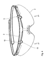
- eine perspektivische Ansicht der Scheibe,
- Fig. 3
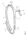
- eine perspektivische Ansicht von oberem Rahmenteil und Bügeln,
- Fig. 4
- Rahmenteil und Scheibe in einem vormontierten Zustand und
- Fig. 5
- Rahmenteil und Scheibe in einem auf Fig. 4 folgendem Montageschritt.
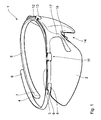
- Eine in der Zeichnung dargestellte Brille 1 umfasst eine einstückige, durchgehende Scheibe 2, ein oberes Rahmenteil 3 und daran einstückig angespritzte Bügel 4, 5, welche sich vom oberen Rahmenteil bogenförmig nach innen gekrümmt und sich im jeweiligen Endbereich 6, 7 überlappend wegerstrecken.
- Das obere Rahmenteil 3 weist einstückig mit diesem gespritzte seitliche Ansätze 8 auf, welche über einen verjüngten Steg 9 mit dem Rahmenteil 3 verbunden sind.
- Beiderseits des Nasenbereichs 10 sind am oberen Rahmenteil 3 hakenartige Ansätze 11 vorgesehen, die sich vom Rahmenteil 3 wegerstreckende Vorsprünge 12 und an deren äußerem Ende angeordnete parallel zum oberen Rahmenteil 3 verlaufende Abschnitte 13 umfassen.
- Die Scheibe 2 weist eine Nasenaufnehmung 14 auf und beiderseits derselben U-förmige Ausnehmungen 15, welche so dimensioniert sind, dass sie die Vorsprünge 12 der hakenartigen Ansätze 11 umgreifen und ihrerseits längs ihres vertikalen Randes von dem Abschnitt 13 der hakenartigen Ansätze 11 übergriffen werden.
- Weiterhin sind an der Scheibe 2 seitlich Ausnehmungen 16 vorgesehen, welche den Steg 9 der Ansätze 8 übergreifen und von den Ansätzen 8 ihrerseits wieder übergriffen werden, wie dies aus Fig. 1 erkennbar ist.
- Einstückig mit dem Rahmenteil 3 erstreckt sich im Nasenbereich 14 von diesem eine vertikale Verlängerung 17 nach unten an deren unterem Ende Nasenpads 18 und ein Hakenansatz 19 ausgebildet sind. Dieser übergreift im eingesetzten Zustand der Scheibe 2 den oberen Bereich der Nasenausnehmung 14.
- Ausgehend von dem in Fig. 2 und 3 dargestellten demontierten Zustand von Rahmenteil 3 einerseits und Scheibe 2 andererseits erfolgt die Befestigung der Scheibe 2 wie folgt:
- Die Scheibe 2 wird im Bereich ihrer Außenseiten in Richtung der Pfeile 20 (vergleiche Fig. 2) etwas weiter nach innen gewölbt, so dass sich ihre effektive Länge verkürzt. Es ist nun möglich, die seitlichen Ausnehmungen 16 unter die Ansätze 8 und über die Stege 9 der Ansätze 8 zu schieben, so dass der in Fig. 4 dargestellte Zustand erreicht wird.
- Hiervon ausgehend wird die Scheibe 2 relativ zum Rahmen 3 nach oben geschwenkt, so dass die U-förmigen Ausnehmungen 15 die Vorsprünge 12 der Ansätze 11 umgreifen und die Abschnitte 13 die seitlichen Außenränder der Ausnehmungen 15 übergreifen.
- Ausgehend von diesem in Fig. 5 dargestellten Zustand wird dann der Hakenansatz 19 im Nasenbereich zusammen mit der Verlängerung 17 in Richtung des Pfeils 22 aus der Zeichenebene heraus nach vorne geschwenkt, so dass der Hakenansatz 19, wie in Fig. 1 dargestellt, über der Nasenausnehmung 14 einrastet.
Claims (8)
- Schamierlose Brille, insbesondere Arbeitsschutzbrille, wobei die Bügel einstückig mit einem oberen Rahmenteil ausgebildet sind und an dem oberen Rahmenteil Befestigungseinrichtungen für die Scheibe ausgebildet sind, dadurch gekennzeichnet, dass die Befestigungseinrichtungen für die Scheibe (2) mit einem eigenelastischen oberen Rahmenteil (3) einstückig aus Kunststoff gespritzt sind.
- Brille nach Anspruch 1, dadurch gekennzeichnet, dass die Bügel (4, 5) sich ausgehend vom oberen Rahmenteil (3) im nicht getragenem Zustand bogenförmig nach innen erstrecken.
- Brille nach Anspruch 1, dadurch gekennzeichnet, dass die Befestigungseinrichtung wenigstens zwei den Brillenrand übergreifende hakenartige Ansätze (11) am oberen Rahmenteil sowie einen in eine Nasenausnehmung (14) der Scheibe (2) einrastbaren, an einer vertikalen Verlängerung (17) des oberen Rahmenteils im Nasenbereich ausgebildeten Hakenansatz (19) umfassen.
- Brille nach Anspruch 3, dadurch gekennzeichnet, dass die Scheibe an ihrer Oberkante U-förmige Ausnehmungen (15) aufweist, welche so dimensioniert sind, dass sie die sich vom oberen Rahmenteil (3) wegerstreckenden Vorsprünge (12) der hakenartigen Ansätze formschlüssig umgreifen, wobei wiederum der seitliche Rand dieser Ausnehmungen von einem querverlaufenden Abschnitt (13) am vorderen Ende der Vorsprünge (12) übergriffen wird.
- Brille nach Anspruch 1, dadurch gekennzeichnet, dass im Bereich des seitlichen äußeren Randes der Scheibe (2) am oberen Rahmenteil (3) Ansätze (8) ausgebildet sind, die den seitlichen oberen Rand der Scheibe (2) im eingesetzten Zustand übergreifen.
- Brille nach Anspruch 5, dadurch gekennzeichnet, dass im Bereich der seitlichen Ansätze (8) des oberen Rahmenteils (3) die Scheibe (2) Ausnehmungen (16) aufweist, welche formschlüssig mit den Ansätzen (8) korrespondieren.
- Brille nach Anspruch 4, dadurch gekennzeichnet, dass die seitlichen Begrenzungswände der U-förmigen Ausnehmungen (15) sich in eine Richtung senkrecht zur Gesichtsebene erstrecken.
- Verfahren zum Befestigen einer einstückigen Scheibe an einem einstückigen Rahmenteil, welches seitlich des Nasenbereiches hakenartige Ansätze, im Nasenbereich einen Hakenansatz und zwei seitliche, den äußeren Rand der Scheibe übergreifende Ansätze aufweist, dadurch gekennzeichnet, dass die Scheibe (2) zur Befestigung an dem Rahmenteil(3) unter Verkürzung ihrer Breite aufgewölbt und mit ihrem Außenrand unter die seitlichen Ansätze (8) eingeschoben wird, dass die Scheibe (2) dann unter die Ansätze (8) seitlich des nahhaften Bereiches geschwenkt wird, und dass abschließend der Hakenansatz (19) im Bereich der Nasenausnehmung (14) der Scheibe (2) eingerastet wird.
Applications Claiming Priority (1)
| Application Number | Priority Date | Filing Date | Title |
|---|---|---|---|
| DE202005009131U DE202005009131U1 (de) | 2005-06-10 | 2005-06-10 | Scharnierlose Brille, insbesondere Arbeitsschutzbrille |
Publications (2)
| Publication Number | Publication Date |
|---|---|
| EP1731946A1 true EP1731946A1 (de) | 2006-12-13 |
| EP1731946B1 EP1731946B1 (de) | 2015-07-29 |
Family
ID=35220269
Family Applications (1)
| Application Number | Title | Priority Date | Filing Date |
|---|---|---|---|
| EP06009587.4A Expired - Lifetime EP1731946B1 (de) | 2005-06-10 | 2006-05-10 | Scharnierlose Brille, insbesondere Arbeitsschutzbrille |
Country Status (5)
| Country | Link |
|---|---|
| US (1) | US7490933B2 (de) |
| EP (1) | EP1731946B1 (de) |
| CN (1) | CN1877395B (de) |
| AU (1) | AU2006202412B2 (de) |
| DE (1) | DE202005009131U1 (de) |
Families Citing this family (23)
| Publication number | Priority date | Publication date | Assignee | Title |
|---|---|---|---|---|
| DE202005009131U1 (de) * | 2005-06-10 | 2005-10-20 | Uvex Arbeitsschutz Gmbh | Scharnierlose Brille, insbesondere Arbeitsschutzbrille |
| USD555701S1 (en) * | 2005-10-31 | 2007-11-20 | Uvex Arbeitsschutz Gmbh | Glasses with flexible temples |
| USRE41097E1 (en) | 2005-06-13 | 2010-02-09 | Uvex Arbeitsschutz Gmbh | Glasses with flexible temples |
| WO2012006164A1 (en) * | 2010-07-06 | 2012-01-12 | Tumi, Inc. | Glasses with stem locks |
| JP5975373B2 (ja) * | 2011-12-27 | 2016-08-23 | 山本光学株式会社 | 眼鏡 |
| EP3749172B2 (de) | 2018-02-09 | 2025-01-01 | Pupil Labs GmbH | Vorrichtungen, systeme und verfahren zur vorhersage von blickbezogenen parametern |
| WO2019154511A1 (en) | 2018-02-09 | 2019-08-15 | Pupil Labs Gmbh | Devices, systems and methods for predicting gaze-related parameters using a neural network |
| WO2019154509A1 (en) * | 2018-02-09 | 2019-08-15 | Pupil Labs Gmbh | Devices, systems and methods for predicting gaze-related parameters |
| DK180074B1 (da) | 2019-02-11 | 2020-03-25 | Lindberg A/S | Selvlåsende brillesystem |
| USD929492S1 (en) * | 2019-03-05 | 2021-08-31 | Uvex Arbeitsschutz Gmbh | Safety goggles |
| EP3979896B1 (de) | 2019-06-05 | 2024-11-13 | Pupil Labs GmbH | Vorrichtungen, systeme und verfahren zur vorhersage von blickbezogenen parametern |
| EP3987380B1 (de) | 2019-06-18 | 2024-10-16 | Pupil Labs GmbH | Systeme und verfahren zur bestimmung eines oder mehrerer parameter des auges eines benutzers |
| CN112394538A (zh) * | 2019-08-19 | 2021-02-23 | 刘振灏 | 一种抑制近视加深的眼镜 |
| CN110908137A (zh) * | 2019-12-27 | 2020-03-24 | 宜宾子午链光学科技有限责任公司 | 一种环抱式镜片可更换运动眼镜 |
| US12140771B2 (en) | 2020-02-19 | 2024-11-12 | Pupil Labs Gmbh | Eye tracking module and head-wearable device |
| DE202020103714U1 (de) * | 2020-06-29 | 2020-07-07 | Günter Krauter | Flexible Brille |
| USD980312S1 (en) * | 2021-03-31 | 2023-03-07 | Deroyal Industries, Inc. | Eye shield |
| USD1008348S1 (en) * | 2021-03-31 | 2023-12-19 | Deroyal Industries, Inc. | Eye shield |
| DE102022210819A1 (de) * | 2022-10-13 | 2024-04-18 | Uvex Arbeitsschutz Gmbh | Brille |
| USD1140996S1 (en) * | 2024-09-11 | 2026-08-11 | Shenzhen Yiwen Tech Limited | Smart glasses |
| USD1130547S1 (en) * | 2024-11-08 | 2026-06-16 | Oakley, Inc. | Eyeglasses |
| USD1130545S1 (en) * | 2024-11-08 | 2026-06-16 | Oakley, Inc. | Eyeglasses |
| USD1130546S1 (en) * | 2024-11-08 | 2026-06-16 | Oakley, Inc. | Eyeglasses |
Citations (9)
| Publication number | Priority date | Publication date | Assignee | Title |
|---|---|---|---|---|
| WO1991017468A1 (en) | 1990-05-07 | 1991-11-14 | Christopher Edward Gilbert | Eyewear |
| EP0561763A1 (de) | 1992-03-16 | 1993-09-22 | SILHOUETTE INTERNATIONAL GESELLSCHAFT m.b.H. | Glashalterung für eine Brille |
| US5760868A (en) | 1996-06-27 | 1998-06-02 | Oakley, Inc. | Unitary hingeless eyeglass frame |
| US5796460A (en) * | 1997-07-28 | 1998-08-18 | Thai Hospital Products Co. Ltd. | Eyeglass protector |
| US5903331A (en) * | 1997-10-08 | 1999-05-11 | Mao Lin Enterprise Co., Ltd. | Eyeglasses comprising frame unit and snap fitted lens unit |
| US6386704B1 (en) | 2001-02-09 | 2002-05-14 | Huei-Min Wu | Sunglasses |
| DE202004002495U1 (de) * | 2004-02-17 | 2004-04-22 | Porsche Design Produkte Vertriebsgesellschaft Mbh | Brille, insbesondere Freizeit- oder Sportbrille |
| DE10105930B4 (de) | 2001-02-09 | 2005-01-05 | König, Björn | Brillenfassung und Verfahren zum Herstellen einer solchen Brillenfassung |
| DE202005009131U1 (de) * | 2005-06-10 | 2005-10-20 | Uvex Arbeitsschutz Gmbh | Scharnierlose Brille, insbesondere Arbeitsschutzbrille |
Family Cites Families (5)
| Publication number | Priority date | Publication date | Assignee | Title |
|---|---|---|---|---|
| US5386254A (en) * | 1993-07-19 | 1995-01-31 | Kahaney; Alan | Sunglasses assembly |
| US5523805A (en) * | 1995-09-15 | 1996-06-04 | Kuipers; Raymond J. | System for coupling lens to an eyeglass frame |
| DE29815895U1 (de) | 1998-09-04 | 1998-11-12 | Todorov, Stefan, 06114 Halle | Brillengestell |
| DE29906003U1 (de) | 1999-04-01 | 1999-09-16 | Brückmann, Ingo, 30655 Hannover | Funktionsbrille mit Aufbewahrungsetui |
| US6908193B2 (en) * | 2001-02-23 | 2005-06-21 | Cabot Safety Intermediate Corporation | Eyewear |
-
2005
- 2005-06-10 DE DE202005009131U patent/DE202005009131U1/de not_active Expired - Lifetime
-
2006
- 2006-05-10 EP EP06009587.4A patent/EP1731946B1/de not_active Expired - Lifetime
- 2006-06-05 CN CN200610088577.8A patent/CN1877395B/zh not_active Expired - Fee Related
- 2006-06-08 AU AU2006202412A patent/AU2006202412B2/en not_active Ceased
- 2006-06-09 US US11/449,757 patent/US7490933B2/en active Active
Patent Citations (9)
| Publication number | Priority date | Publication date | Assignee | Title |
|---|---|---|---|---|
| WO1991017468A1 (en) | 1990-05-07 | 1991-11-14 | Christopher Edward Gilbert | Eyewear |
| EP0561763A1 (de) | 1992-03-16 | 1993-09-22 | SILHOUETTE INTERNATIONAL GESELLSCHAFT m.b.H. | Glashalterung für eine Brille |
| US5760868A (en) | 1996-06-27 | 1998-06-02 | Oakley, Inc. | Unitary hingeless eyeglass frame |
| US5796460A (en) * | 1997-07-28 | 1998-08-18 | Thai Hospital Products Co. Ltd. | Eyeglass protector |
| US5903331A (en) * | 1997-10-08 | 1999-05-11 | Mao Lin Enterprise Co., Ltd. | Eyeglasses comprising frame unit and snap fitted lens unit |
| US6386704B1 (en) | 2001-02-09 | 2002-05-14 | Huei-Min Wu | Sunglasses |
| DE10105930B4 (de) | 2001-02-09 | 2005-01-05 | König, Björn | Brillenfassung und Verfahren zum Herstellen einer solchen Brillenfassung |
| DE202004002495U1 (de) * | 2004-02-17 | 2004-04-22 | Porsche Design Produkte Vertriebsgesellschaft Mbh | Brille, insbesondere Freizeit- oder Sportbrille |
| DE202005009131U1 (de) * | 2005-06-10 | 2005-10-20 | Uvex Arbeitsschutz Gmbh | Scharnierlose Brille, insbesondere Arbeitsschutzbrille |
Also Published As
| Publication number | Publication date |
|---|---|
| HK1131515A1 (en) | 2010-01-15 |
| US7490933B2 (en) | 2009-02-17 |
| AU2006202412A1 (en) | 2007-01-04 |
| AU2006202412B2 (en) | 2011-03-03 |
| DE202005009131U1 (de) | 2005-10-20 |
| US20060279692A1 (en) | 2006-12-14 |
| CN1877395B (zh) | 2010-06-16 |
| EP1731946B1 (de) | 2015-07-29 |
| CN1877395A (zh) | 2006-12-13 |
Similar Documents
| Publication | Publication Date | Title |
|---|---|---|
| EP1731946B1 (de) | Scharnierlose Brille, insbesondere Arbeitsschutzbrille | |
| EP1585657B1 (de) | Wischvorrichtung für scheiben von kraftfahrzeugen | |
| DE112011103091B4 (de) | Universelles Kopplungselement für eine Windschutzscheibenwischeranordnung vom Typ Balkenblatt | |
| EP1547884B1 (de) | Wischblatt zum Reinigen von Scheiben insbesondere von Kraftfahrzeugen | |
| DE602005005005T2 (de) | Scheibenwischvorrichtung | |
| DE102008022200B4 (de) | Bremsbelaganordnung für Scheibenbremsen | |
| DE112011103907B4 (de) | Flachbalken-Scheibenwischeranordnung mit selbstverriegelnder Endkappe | |
| DE102010042095A1 (de) | Wischblatt | |
| DE102004019157A1 (de) | Wischblatt | |
| DE10038812A1 (de) | Frontklappe für ein Kraftfahrzeug | |
| DE19716065A1 (de) | Vorrichtung zur Befestigung einer verschiebbaren Fensterscheibe an einem Fensterheber eines Kraftfahrzeugs | |
| EP1984593B1 (de) | Vorrichtung zum verschiebbaren halten einer glasscheibe in einer gleitschiene | |
| DE60214306T2 (de) | Schwimmbrille | |
| EP2373863B1 (de) | Anordnung mit einen beschlag für eine schiebetür aus glas | |
| DE102012021489A1 (de) | Verbindungsanordnung eines Wischarms einer Scheibenwischanlage mit einem Wischblatt sowie Wischblatt und Wischarm einer solchen Verbindungsanordnung | |
| DE4025706C2 (de) | Plattenförderband | |
| DE102004019158A1 (de) | Wischblatt | |
| DE102015116657A1 (de) | Stabband für Stabförderer landwirtschaftlicher Maschinen | |
| DE60225456T2 (de) | Lichteinheit für fahrzeugscheinwerfer | |
| DE602004008210T2 (de) | Scheibenwischeranlage | |
| DE102013217985A1 (de) | Befestigungsvorrichtung für eine Scheibenwischvorrichtung | |
| DE10226103C1 (de) | Anordnung mit einer Backe, einem Bügel und einem Gelenk für eine Brille | |
| DE102011079486A1 (de) | Vorrichtung zum gelenkigen Verbinden eines Wischblatts in Flachbalkenbauweise mit einem Wischarm nach dem Sidelockprinzip | |
| DE202011101672U1 (de) | Brille | |
| WO2005002934A1 (de) | Verbindung zwischen einem wischblatt und einem wischarm einer wischvorrichtung für scheiben an fahrzeugen, sowie wischvorrichtung mit einer solchen verbindung |
Legal Events
| Date | Code | Title | Description |
|---|---|---|---|
| PUAI | Public reference made under article 153(3) epc to a published international application that has entered the european phase |
Free format text: ORIGINAL CODE: 0009012 |
|
| 17P | Request for examination filed |
Effective date: 20061028 |
|
| AK | Designated contracting states |
Kind code of ref document: A1 Designated state(s): AT BE BG CH CY CZ DE DK EE ES FI FR GB GR HU IE IS IT LI LT LU LV MC NL PL PT RO SE SI SK TR |
|
| AX | Request for extension of the european patent |
Extension state: AL BA HR MK YU |
|
| 17Q | First examination report despatched |
Effective date: 20070122 |
|
| AKX | Designation fees paid |
Designated state(s): AT BE BG CH CY CZ DE DK EE ES FI FR GB GR HU IE IS IT LI LT LU LV MC NL PL PT RO SE SI SK TR |
|
| GRAP | Despatch of communication of intention to grant a patent |
Free format text: ORIGINAL CODE: EPIDOSNIGR1 |
|
| INTG | Intention to grant announced |
Effective date: 20150326 |
|
| GRAS | Grant fee paid |
Free format text: ORIGINAL CODE: EPIDOSNIGR3 |
|
| GRAA | (expected) grant |
Free format text: ORIGINAL CODE: 0009210 |
|
| AK | Designated contracting states |
Kind code of ref document: B1 Designated state(s): AT BE BG CH CY CZ DE DK EE ES FI FR GB GR HU IE IS IT LI LT LU LV MC NL PL PT RO SE SI SK TR |
|
| REG | Reference to a national code |
Ref country code: GB Ref legal event code: FG4D Free format text: NOT ENGLISH |
|
| REG | Reference to a national code |
Ref country code: CH Ref legal event code: EP |
|
| REG | Reference to a national code |
Ref country code: AT Ref legal event code: REF Ref document number: 739753 Country of ref document: AT Kind code of ref document: T Effective date: 20150815 |
|
| REG | Reference to a national code |
Ref country code: IE Ref legal event code: FG4D Free format text: LANGUAGE OF EP DOCUMENT: GERMAN |
|
| REG | Reference to a national code |
Ref country code: NL Ref legal event code: T3 |
|
| REG | Reference to a national code |
Ref country code: DE Ref legal event code: R096 Ref document number: 502006014440 Country of ref document: DE |
|
| REG | Reference to a national code |
Ref country code: LT Ref legal event code: MG4D |
|
| PG25 | Lapsed in a contracting state [announced via postgrant information from national office to epo] |
Ref country code: LT Free format text: LAPSE BECAUSE OF FAILURE TO SUBMIT A TRANSLATION OF THE DESCRIPTION OR TO PAY THE FEE WITHIN THE PRESCRIBED TIME-LIMIT Effective date: 20150729 Ref country code: GR Free format text: LAPSE BECAUSE OF FAILURE TO SUBMIT A TRANSLATION OF THE DESCRIPTION OR TO PAY THE FEE WITHIN THE PRESCRIBED TIME-LIMIT Effective date: 20151030 Ref country code: LV Free format text: LAPSE BECAUSE OF FAILURE TO SUBMIT A TRANSLATION OF THE DESCRIPTION OR TO PAY THE FEE WITHIN THE PRESCRIBED TIME-LIMIT Effective date: 20150729 Ref country code: FI Free format text: LAPSE BECAUSE OF FAILURE TO SUBMIT A TRANSLATION OF THE DESCRIPTION OR TO PAY THE FEE WITHIN THE PRESCRIBED TIME-LIMIT Effective date: 20150729 |
|
| PG25 | Lapsed in a contracting state [announced via postgrant information from national office to epo] |
Ref country code: IS Free format text: LAPSE BECAUSE OF FAILURE TO SUBMIT A TRANSLATION OF THE DESCRIPTION OR TO PAY THE FEE WITHIN THE PRESCRIBED TIME-LIMIT Effective date: 20151129 Ref country code: PT Free format text: LAPSE BECAUSE OF FAILURE TO SUBMIT A TRANSLATION OF THE DESCRIPTION OR TO PAY THE FEE WITHIN THE PRESCRIBED TIME-LIMIT Effective date: 20151130 Ref country code: PL Free format text: LAPSE BECAUSE OF FAILURE TO SUBMIT A TRANSLATION OF THE DESCRIPTION OR TO PAY THE FEE WITHIN THE PRESCRIBED TIME-LIMIT Effective date: 20150729 Ref country code: ES Free format text: LAPSE BECAUSE OF FAILURE TO SUBMIT A TRANSLATION OF THE DESCRIPTION OR TO PAY THE FEE WITHIN THE PRESCRIBED TIME-LIMIT Effective date: 20150729 Ref country code: SE Free format text: LAPSE BECAUSE OF FAILURE TO SUBMIT A TRANSLATION OF THE DESCRIPTION OR TO PAY THE FEE WITHIN THE PRESCRIBED TIME-LIMIT Effective date: 20150729 |
|
| PG25 | Lapsed in a contracting state [announced via postgrant information from national office to epo] |
Ref country code: EE Free format text: LAPSE BECAUSE OF FAILURE TO SUBMIT A TRANSLATION OF THE DESCRIPTION OR TO PAY THE FEE WITHIN THE PRESCRIBED TIME-LIMIT Effective date: 20150729 Ref country code: SK Free format text: LAPSE BECAUSE OF FAILURE TO SUBMIT A TRANSLATION OF THE DESCRIPTION OR TO PAY THE FEE WITHIN THE PRESCRIBED TIME-LIMIT Effective date: 20150729 Ref country code: CZ Free format text: LAPSE BECAUSE OF FAILURE TO SUBMIT A TRANSLATION OF THE DESCRIPTION OR TO PAY THE FEE WITHIN THE PRESCRIBED TIME-LIMIT Effective date: 20150729 Ref country code: DK Free format text: LAPSE BECAUSE OF FAILURE TO SUBMIT A TRANSLATION OF THE DESCRIPTION OR TO PAY THE FEE WITHIN THE PRESCRIBED TIME-LIMIT Effective date: 20150729 |
|
| REG | Reference to a national code |
Ref country code: DE Ref legal event code: R097 Ref document number: 502006014440 Country of ref document: DE |
|
| PG25 | Lapsed in a contracting state [announced via postgrant information from national office to epo] |
Ref country code: RO Free format text: LAPSE BECAUSE OF FAILURE TO SUBMIT A TRANSLATION OF THE DESCRIPTION OR TO PAY THE FEE WITHIN THE PRESCRIBED TIME-LIMIT Effective date: 20150729 |
|
| PLBE | No opposition filed within time limit |
Free format text: ORIGINAL CODE: 0009261 |
|
| STAA | Information on the status of an ep patent application or granted ep patent |
Free format text: STATUS: NO OPPOSITION FILED WITHIN TIME LIMIT |
|
| 26N | No opposition filed |
Effective date: 20160502 |
|
| PG25 | Lapsed in a contracting state [announced via postgrant information from national office to epo] |
Ref country code: SI Free format text: LAPSE BECAUSE OF FAILURE TO SUBMIT A TRANSLATION OF THE DESCRIPTION OR TO PAY THE FEE WITHIN THE PRESCRIBED TIME-LIMIT Effective date: 20150729 Ref country code: BE Free format text: LAPSE BECAUSE OF NON-PAYMENT OF DUE FEES Effective date: 20160531 |
|
| PG25 | Lapsed in a contracting state [announced via postgrant information from national office to epo] |
Ref country code: LU Free format text: LAPSE BECAUSE OF FAILURE TO SUBMIT A TRANSLATION OF THE DESCRIPTION OR TO PAY THE FEE WITHIN THE PRESCRIBED TIME-LIMIT Effective date: 20160510 |
|
| REG | Reference to a national code |
Ref country code: IE Ref legal event code: MM4A |
|
| REG | Reference to a national code |
Ref country code: FR Ref legal event code: ST Effective date: 20170131 |
|
| PG25 | Lapsed in a contracting state [announced via postgrant information from national office to epo] |
Ref country code: FR Free format text: LAPSE BECAUSE OF NON-PAYMENT OF DUE FEES Effective date: 20160531 |
|
| PG25 | Lapsed in a contracting state [announced via postgrant information from national office to epo] |
Ref country code: IE Free format text: LAPSE BECAUSE OF NON-PAYMENT OF DUE FEES Effective date: 20160510 |
|
| PG25 | Lapsed in a contracting state [announced via postgrant information from national office to epo] |
Ref country code: HU Free format text: LAPSE BECAUSE OF FAILURE TO SUBMIT A TRANSLATION OF THE DESCRIPTION OR TO PAY THE FEE WITHIN THE PRESCRIBED TIME-LIMIT; INVALID AB INITIO Effective date: 20060510 Ref country code: CY Free format text: LAPSE BECAUSE OF FAILURE TO SUBMIT A TRANSLATION OF THE DESCRIPTION OR TO PAY THE FEE WITHIN THE PRESCRIBED TIME-LIMIT Effective date: 20150729 |
|
| PG25 | Lapsed in a contracting state [announced via postgrant information from national office to epo] |
Ref country code: TR Free format text: LAPSE BECAUSE OF FAILURE TO SUBMIT A TRANSLATION OF THE DESCRIPTION OR TO PAY THE FEE WITHIN THE PRESCRIBED TIME-LIMIT Effective date: 20150729 Ref country code: MC Free format text: LAPSE BECAUSE OF FAILURE TO SUBMIT A TRANSLATION OF THE DESCRIPTION OR TO PAY THE FEE WITHIN THE PRESCRIBED TIME-LIMIT Effective date: 20150729 |
|
| PG25 | Lapsed in a contracting state [announced via postgrant information from national office to epo] |
Ref country code: BG Free format text: LAPSE BECAUSE OF FAILURE TO SUBMIT A TRANSLATION OF THE DESCRIPTION OR TO PAY THE FEE WITHIN THE PRESCRIBED TIME-LIMIT Effective date: 20150729 |
|
| P01 | Opt-out of the competence of the unified patent court (upc) registered |
Effective date: 20230502 |
|
| PGFP | Annual fee paid to national office [announced via postgrant information from national office to epo] |
Ref country code: NL Payment date: 20240522 Year of fee payment: 19 |
|
| PGFP | Annual fee paid to national office [announced via postgrant information from national office to epo] |
Ref country code: GB Payment date: 20240522 Year of fee payment: 19 |
|
| PGFP | Annual fee paid to national office [announced via postgrant information from national office to epo] |
Ref country code: CH Payment date: 20240602 Year of fee payment: 19 |
|
| PGFP | Annual fee paid to national office [announced via postgrant information from national office to epo] |
Ref country code: AT Payment date: 20240410 Year of fee payment: 19 |
|
| PGFP | Annual fee paid to national office [announced via postgrant information from national office to epo] |
Ref country code: IT Payment date: 20240531 Year of fee payment: 19 |
|
| PGFP | Annual fee paid to national office [announced via postgrant information from national office to epo] |
Ref country code: DE Payment date: 20240712 Year of fee payment: 19 |
|
| REG | Reference to a national code |
Ref country code: DE Ref legal event code: R119 Ref document number: 502006014440 Country of ref document: DE |
|
| REG | Reference to a national code |
Ref country code: CH Ref legal event code: H13 Free format text: ST27 STATUS EVENT CODE: U-0-0-H10-H13 (AS PROVIDED BY THE NATIONAL OFFICE) Effective date: 20251223 |
|
| REG | Reference to a national code |
Ref country code: NL Ref legal event code: MM Effective date: 20250601 |
|
| PG25 | Lapsed in a contracting state [announced via postgrant information from national office to epo] |
Ref country code: AT Free format text: LAPSE BECAUSE OF NON-PAYMENT OF DUE FEES Effective date: 20250510 |
|
| REG | Reference to a national code |
Ref country code: AT Ref legal event code: MM01 Ref document number: 739753 Country of ref document: AT Kind code of ref document: T Effective date: 20250510 |
|
| PG25 | Lapsed in a contracting state [announced via postgrant information from national office to epo] |
Ref country code: CH Free format text: LAPSE BECAUSE OF NON-PAYMENT OF DUE FEES Effective date: 20250531 |
|
| GBPC | Gb: european patent ceased through non-payment of renewal fee |
Effective date: 20250510 |
|
| PG25 | Lapsed in a contracting state [announced via postgrant information from national office to epo] |
Ref country code: NL Free format text: LAPSE BECAUSE OF NON-PAYMENT OF DUE FEES Effective date: 20250601 |
|
| PG25 | Lapsed in a contracting state [announced via postgrant information from national office to epo] |
Ref country code: GB Free format text: LAPSE BECAUSE OF NON-PAYMENT OF DUE FEES Effective date: 20250510 |
|
| PG25 | Lapsed in a contracting state [announced via postgrant information from national office to epo] |
Ref country code: DE Free format text: LAPSE BECAUSE OF NON-PAYMENT OF DUE FEES Effective date: 20251202 |
|
| PG25 | Lapsed in a contracting state [announced via postgrant information from national office to epo] |
Ref country code: IT Free format text: LAPSE BECAUSE OF NON-PAYMENT OF DUE FEES Effective date: 20250510 |