EP1731826B1 - Auslöser eines Druckmittelspeichers - Google Patents
Auslöser eines Druckmittelspeichers Download PDFInfo
- Publication number
- EP1731826B1 EP1731826B1 EP06010896A EP06010896A EP1731826B1 EP 1731826 B1 EP1731826 B1 EP 1731826B1 EP 06010896 A EP06010896 A EP 06010896A EP 06010896 A EP06010896 A EP 06010896A EP 1731826 B1 EP1731826 B1 EP 1731826B1
- Authority
- EP
- European Patent Office
- Prior art keywords
- pin
- receiving bore
- bore
- balls
- trigger according
- Prior art date
- Legal status (The legal status is an assumption and is not a legal conclusion. Google has not performed a legal analysis and makes no representation as to the accuracy of the status listed.)
- Active
Links
Images




Classifications
-
- F—MECHANICAL ENGINEERING; LIGHTING; HEATING; WEAPONS; BLASTING
- F16—ENGINEERING ELEMENTS AND UNITS; GENERAL MEASURES FOR PRODUCING AND MAINTAINING EFFECTIVE FUNCTIONING OF MACHINES OR INSTALLATIONS; THERMAL INSULATION IN GENERAL
- F16K—VALVES; TAPS; COCKS; ACTUATING-FLOATS; DEVICES FOR VENTING OR AERATING
- F16K17/00—Safety valves; Equalising valves, e.g. pressure relief valves
- F16K17/36—Safety valves; Equalising valves, e.g. pressure relief valves actuated in consequence of extraneous circumstances, e.g. shock, change of position
- F16K17/38—Safety valves; Equalising valves, e.g. pressure relief valves actuated in consequence of extraneous circumstances, e.g. shock, change of position of excessive temperature
- F16K17/383—Safety valves; Equalising valves, e.g. pressure relief valves actuated in consequence of extraneous circumstances, e.g. shock, change of position of excessive temperature the valve comprising fusible, softening or meltable elements, e.g. used as link, blocking element, seal, closure plug
-
- A—HUMAN NECESSITIES
- A62—LIFE-SAVING; FIRE-FIGHTING
- A62C—FIRE-FIGHTING
- A62C99/00—Subject matter not provided for in other groups of this subclass
- A62C99/009—Methods or equipment not provided for in groups A62C99/0009 - A62C99/0081
-
- F—MECHANICAL ENGINEERING; LIGHTING; HEATING; WEAPONS; BLASTING
- F16—ENGINEERING ELEMENTS AND UNITS; GENERAL MEASURES FOR PRODUCING AND MAINTAINING EFFECTIVE FUNCTIONING OF MACHINES OR INSTALLATIONS; THERMAL INSULATION IN GENERAL
- F16K—VALVES; TAPS; COCKS; ACTUATING-FLOATS; DEVICES FOR VENTING OR AERATING
- F16K31/00—Actuating devices; Operating means; Releasing devices
- F16K31/003—Actuating devices; Operating means; Releasing devices operated without a stable intermediate position, e.g. with snap action
-
- F—MECHANICAL ENGINEERING; LIGHTING; HEATING; WEAPONS; BLASTING
- F17—STORING OR DISTRIBUTING GASES OR LIQUIDS
- F17C—VESSELS FOR CONTAINING OR STORING COMPRESSED, LIQUEFIED OR SOLIDIFIED GASES; FIXED-CAPACITY GAS-HOLDERS; FILLING VESSELS WITH, OR DISCHARGING FROM VESSELS, COMPRESSED, LIQUEFIED, OR SOLIDIFIED GASES
- F17C2205/00—Vessel construction, in particular mounting arrangements, attachments or identifications means
- F17C2205/03—Fluid connections, filters, valves, closure means or other attachments
- F17C2205/0302—Fittings, valves, filters, or components in connection with the gas storage device
- F17C2205/0311—Closure means
- F17C2205/032—Closure means pierceable
-
- F—MECHANICAL ENGINEERING; LIGHTING; HEATING; WEAPONS; BLASTING
- F17—STORING OR DISTRIBUTING GASES OR LIQUIDS
- F17C—VESSELS FOR CONTAINING OR STORING COMPRESSED, LIQUEFIED OR SOLIDIFIED GASES; FIXED-CAPACITY GAS-HOLDERS; FILLING VESSELS WITH, OR DISCHARGING FROM VESSELS, COMPRESSED, LIQUEFIED, OR SOLIDIFIED GASES
- F17C2221/00—Handled fluid, in particular type of fluid
- F17C2221/01—Pure fluids
- F17C2221/013—Carbon dioxide
-
- F—MECHANICAL ENGINEERING; LIGHTING; HEATING; WEAPONS; BLASTING
- F17—STORING OR DISTRIBUTING GASES OR LIQUIDS
- F17C—VESSELS FOR CONTAINING OR STORING COMPRESSED, LIQUEFIED OR SOLIDIFIED GASES; FIXED-CAPACITY GAS-HOLDERS; FILLING VESSELS WITH, OR DISCHARGING FROM VESSELS, COMPRESSED, LIQUEFIED, OR SOLIDIFIED GASES
- F17C2223/00—Handled fluid before transfer, i.e. state of fluid when stored in the vessel or before transfer from the vessel
- F17C2223/01—Handled fluid before transfer, i.e. state of fluid when stored in the vessel or before transfer from the vessel characterised by the phase
- F17C2223/0107—Single phase
- F17C2223/0123—Single phase gaseous, e.g. CNG, GNC
-
- F—MECHANICAL ENGINEERING; LIGHTING; HEATING; WEAPONS; BLASTING
- F17—STORING OR DISTRIBUTING GASES OR LIQUIDS
- F17C—VESSELS FOR CONTAINING OR STORING COMPRESSED, LIQUEFIED OR SOLIDIFIED GASES; FIXED-CAPACITY GAS-HOLDERS; FILLING VESSELS WITH, OR DISCHARGING FROM VESSELS, COMPRESSED, LIQUEFIED, OR SOLIDIFIED GASES
- F17C2223/00—Handled fluid before transfer, i.e. state of fluid when stored in the vessel or before transfer from the vessel
- F17C2223/03—Handled fluid before transfer, i.e. state of fluid when stored in the vessel or before transfer from the vessel characterised by the pressure level
- F17C2223/035—High pressure (>10 bar)
-
- F—MECHANICAL ENGINEERING; LIGHTING; HEATING; WEAPONS; BLASTING
- F17—STORING OR DISTRIBUTING GASES OR LIQUIDS
- F17C—VESSELS FOR CONTAINING OR STORING COMPRESSED, LIQUEFIED OR SOLIDIFIED GASES; FIXED-CAPACITY GAS-HOLDERS; FILLING VESSELS WITH, OR DISCHARGING FROM VESSELS, COMPRESSED, LIQUEFIED, OR SOLIDIFIED GASES
- F17C2270/00—Applications
- F17C2270/07—Applications for household use
- F17C2270/0736—Capsules, e.g. CO2
Definitions
- the invention relates to a trigger for triggering a pressure medium accumulator, in particular a CO 2 disposable bottle according to the preamble of claim 1.
- a CO 2 disposable bottle or CO 2 cartridge can be attached, the closure portion can be opened with the shutter to provide a fluid connection, for example to a cylinder chamber of a pneumatic cylinder, whereby the pneumatic cylinder is activated, which is an adjustable element, in particular a smoke outlet flap in a smoke and heat exhaust system, operated.
- a pressure fluid accumulator of the type mentioned has a tensionable with a tension spring piercing, which carries at one end against a closure portion of the accumulator a piercing tip, and a releasable locking of the piercing.
- the lock comprises a receiving bore in which a series of abutting locking elements including balls are received.
- the receiving bore is transverse to arranged the piercing, namely transversely to a formation in the piercing in the form of conical approaches in operational position, in which engages one of the balls in the formation.
- In the receiving bore opens a transverse bore in which a release bolt is displaceable.
- the receiving bore is pierced at one of the transverse bore opposite point and limited by a resilient wall element. At least one of the balls lies between the release bolt and the resilient wall element and can thus be resiliently pushed out by the release bolt from a centered in the receiving bore position.
- the generic trigger is thus a spring-biased release with a tensionable with a tension spring piercing bolt, which carries a piercing tip on one of the closure portion of the accumulator end facing.
- the cocked piercing bolt is locked in operational position and the lock can be solved, for example, in an alarm, such as fire alarm, whereby the piercing bolt under the force of the tension spring the piercing in the closure portion of the accumulator pushes, which is thus opened.
- the release of the lock can be done arbitrarily manually or electromagnetically.
- the CO 2 release include those with spring release in conjunction with locking releases such as toggle releases.
- the spring-loaded triggers are used in particular for magnetic tripping to minimize tripping forces.
- the triggers are also referred to as tripping valves and may be combined with additional valves.
- the known triggers require a production and assembly with very high precision, which are costly.
- the present invention is therefore based on the object to simplify the production of the shutter, whereby manufacturing costs can be saved, and nevertheless to achieve a high reliability of the shutter.
- the invention is based on the fact that the locking of the in the position ready tensioning piercing pin by a series of centered in a receiving bore adjacent locking elements including balls takes place, of which an outer ball abuts in a groove as a formation in the piercing bolt, to which the receiving bore transversely is arranged.
- two balls of the row are pressed transversely out of the centered position by the release bolt, whereby space in the receiving bore is released, in which the outer ball moves out of the groove of the prestressing piercing bolt, wherein it can move other locking elements or balls.
- the piercing whose groove is thus freed from the outer ball can pierce the closure portion of the accumulator, in particular the CO 2 disposable bottle or cartridge by the action of the tension spring with his piercing.
- the locating bore is broken from the locating pin and bounded by a resilient wall element.
- the release bolt In order to reach the position "ready for operation", the release bolt is withdrawn from the mounting hole. Then, when the groove of the piercing bolt is aligned again with the receiving bore of the locking elements, the outer ball of the series arresting elements or balls penetrates again into the groove, because the previously pushed out of the row balls through the resilient wall element of the receiving bore back into the centered position be pushed back in the ball row. Because these previously pushed out of the centered row balls and the resilient wall element are no longer under the release pressure of the release bolt. The locking elements or balls in the receiving bore are held by the resilient wall element in position, even if now the biasing force of the tension spring is increased to the piercing, whereby the shutter is locked ready for use again.
- the juxtaposed balls cause a very reliable locking, which replaces the principle of a toggle lever and improved.
- the balls and others Elements can be standard standard parts that are available from mass production with high accuracy and at low cost.
- the groove as a shape of the piercing pin chamfered or conical side walls on which an outer of the balls in the position "ready” applies.
- At least one cylindrical pin can be arranged in the receiving bore between the ball on the groove of the piercing bolt and one of the balls up to the resilient wall element. With the cylinder pin ensures that can affect any negative influences of the possibly rotating piercing the balls in the region of the resilient wall element.
- the resilient wall element can be easily realized by a particular flat disc, which adjoins a lateral opening of the receiving bore.
- the disc is loaded by a spring, in particular a compression spring which presses the disc against the balls in the receiving bore.
- the release bolt on the opposite side of the disc or the resilient wall element can be manually operated, but also according to claim 5 expedient with an electromagnetic actuator or magnetic release in connection for which the shutter is well suited because the release force is low.
- the trigger can be designed compactly with at least one mounting block according to claim 7, in which the receiving bore with the transverse bore for the release bolt and a disc and spring receptacle, the piercing bolt receiving bore with a connection opening for the accumulator, a threaded hole for the clamping mechanism and a pressure medium channel are formed.
- a magnetic release can be attached to the outside of the mounting block.
- Low mounting can be covered in the metal housing to the outside by che cover according to claim 9, the receiving bore and the disc and spring receptacle.
- the covers may be detachable for maintenance or repair purposes.
- a seal of the area in which the pressure medium flows from the environment according to claim 10 expediently by a sealing O-ring between two locking elements, in particular between the outer ball on the piercing bolt and an adjacent cylinder pin.
- FIGS. 1 to 4 is a mounting block 1, from which a bore 2 for a piercing bolt 3, a threaded bore 4 for a clamping mechanism 5 concentric with the bore 2 and the piercing 3 are formed.
- a clamping mechanism 5 At one in FIG. 1 lower end of the clamping mechanism is an adjusting screw 6, with which a tension spring 7 can be tightened, which is supported on a flange 8 of the piercing bolt 3 to push it in the direction of a connection opening 9 in the mounting block, a CO 2 cartridge receives.
- the piercing bolt 3 is provided with a piercing needle 11.
- the bore 2 for the piercing bolt forms a pressure chamber, which communicates with a transverse bore 12 in connection, in which a piston 13 of a display device 14 is slidably mounted, and with a non-designated pressure medium channel.
- the piercing bolt 3 with the piercing needle 11, the clamping mechanism 5 of the piercing, the connection opening for the CO 2 cartridge and the display device 14 are prior art and therefore need not be described in detail.
- the trigger is shown in its "ready to use” position.
- the piercing bolt 3 has a circumferential groove 15 with oblique or conical side walls 16, 17, in which a locking element in the form of a ball 20 can engage.
- a receiving bore 18 which is open at least at its the groove 1 5 facing the end and in the present embodiment may also be open at its opposite end to the mounting block, for example, to introduce the locking elements in the receiving bore, after which the end by a flat Cover 19 can be closed.
- the locking elements consist in detail in the in the FIGS.
- the cylindrical pin 25 is located between the ball 20, which can engage as an outer ball of the series in the groove 15 of the piercing bolt 3, and the ball 21 of the balls arranged in series.
- an O-ring 26 may be disposed in the receiving bore 18 to the bore 2 for the piercing complete the environment of the receiving bore 18.
- the locking elements namely the balls 20 - 24 and the cylindrical pin 25 centered in the longitudinal axis of the receiving bore 18 abut each other, the outer ball 20 is in the groove 15 and the opposite outer ball 24 via an O Ring 27 presses against the cover 19.
- the centered row locking elements has a greater longitudinal extent than the arrangement of the locking elements in the position "triggered”.
- the receiving bore 18 has a lateral recess 28, see FIG. 9 , by a resilient wall element in the form of a disc 29, which under the pressure of an example in FIG. 2 indicated spring 30 is, so that the disc 29 is pressed in the direction of the axis of the receiving bore 18.
- the disc 29 and the spring 30 are in a hollow disc and spring receptacle 31 in the Mounting block 1 arranged, see FIG. 9 ,
- the mounting block On the side opposite to the disc and spring receptacle 31 side of the receiving bore 18, the mounting block has a transverse bore 32 which extends from the outside transversely to the receiving bore 18 and in which a release pin 33 is slidably mounted.
- the release bolt may externally communicate with a manual actuator, which is not shown in the drawing.
- the release bolt 33 is in the in the FIGS. 4 and 9 shown pressed position in which the trigger pin 33, the balls 22 and 23 of the locking elements 20 - 25 in the lateral recess 28 to the in FIG. 9 position shown below the balls 21, 22 adjacent to each other, whereby the extension of the arrangement of the locking elements in the receiving bore 18 is shortened in the direction of their unspecified longitudinal axis, whereby space is released in the receiving bore.
- the outer ball 20 can slide out of the groove 15 under the action of the tension spring 7, as in FIGS. 3, 4 . 9 shown.
- FIG. 3 is "tripped" position, the piercing needle thrust 11 in the CO 2 cartridge 10 so that CO 2 2 cartridge can flow into the bore 2 from the CO.
- the effluent CO 2 can operate an unillustrated integrated valve, such as a priority valve or an alarm or ventilation valve of a smoke and heat exhaust system.
- the position "triggered” is displayed with the display device 14 as a result of displacement of the piston 13 in the transverse bore 12.
- the groove 1 5 can be aligned with the unspecified longitudinal axis of the receiving bore 18 again, and the outer ball 20 in the groove 15 arrive. It is thereby automatically pushed into the groove that the partially out of the receiving bore 18 balls 22, 23 are pushed back completely into the receiving bore 18 through the disc 29 due to the force of the spring 30, so that all locking elements 20 - 25 centered in a row lie, which extends from the cover 1 9 into the groove 15. Even if the biasing force of the tension spring 7 is increased again, the piercing bolt 3 remains in its in FIG. 1 shown position, since the outer ball 20 bears against the side wall 17 and surface of the groove 15 and the balls 22, 23 are held by the spring 29 acting on the disc 30 in position. The trigger is ready for use again.
- FIGS. 5 to 8 illustrated second embodiment with an additional electromagnetic actuator is basically constructed as the embodiment described above, in which the release bolt is in communication with a manual actuator. The same parts are therefore provided with the same reference numerals. Also, the effect of the second embodiment of the trigger is the same as that of the first embodiment except for the additional electromagnetic operation.
- electromagnetic actuator which essentially comprises an electromagnet 36 which a magnetic ram 37th between one retracted position, see FIG. 5 , and an advanced position, see FIG. 7 , can adjust.
- the trigger with this magnetic release belonging to the series locking elements further balls, which are designated 38-41, corresponding to the greater length of the receiving bore 42 in the extended mounting block to which the electromagnetic actuator 35 mounted next to a manual actuator, not shown is.
- the actuatable with the electromagnetic actuator 35 release bolt 34 and the actuatable with the manual actuator release bolt 33 are rotated by 90 ° from each other in the mounting block 43.
Landscapes
- Engineering & Computer Science (AREA)
- General Engineering & Computer Science (AREA)
- Mechanical Engineering (AREA)
- Health & Medical Sciences (AREA)
- Public Health (AREA)
- Business, Economics & Management (AREA)
- Emergency Management (AREA)
- Portable Nailing Machines And Staplers (AREA)
- Refuse Collection And Transfer (AREA)
- Finger-Pressure Massage (AREA)
- Clamps And Clips (AREA)
- Coating Apparatus (AREA)
Description
- Die Erfindung betrifft einen Auslöser zur Auslösung eines Druckmittelspeichers, insbesondere einer CO2-Einwegflasche nach dem Oberbegriff des Anspruchs 1.
- An derartige Auslöser kann eine CO2-Einwegflasche bzw. CO2-Patrone angebracht werden, dessen Verschlußabschnitt mit dem Auslöser geöffnet werden kann, um eine Druckmittelverbindung beispielsweise zu einem Zylinderraum eines Pneumatikzylinders zu schaffen, wodurch der Pneumatikzylinder aktiviert wird, der ein einstellbares Element, insbesondere eine Rauchabzugsklappe in einer Rauch- und Wärmeabzugsanlage, betätigt.
- Ein aus der
DE-U-8 326 617 bekannter Auslöser eines Druckmittelspeichers der eingangs genannten Gattung weist einen mit einer Spannfeder spannbaren Anstechbolzen, der an einem Ende gegenüber einem Verschlussabschnitt des Druckmittelspeichers eine Anstechspitze trägt, sowie eine lösbare Arretierung des Anstechbolzens auf. Die Arretierung umfasst eine Aufnahmebohrung, in der eine Reihe aneinanderstoßender Arretierungselemente einschließlich Kugeln aufgenommen sind. Die Aufnahmebohrung ist quer zu dem Anstechbolzen angeordnet, und zwar quer zu einer Ausformung in dem Anstechbolzen in Form konischer Ansätze in betriebsbereiter Position, in der eine der Kugeln in die Ausformung eingreift. In die Aufnahmebohrung mündet eine Querbohrung, in der ein Auslösebolzen verschiebbar ist. Die Aufnahmebohrung ist an einer der Querbohrung gegenüberliegenden Stelle durchbrochen und durch ein federnd nachgiebiges Wandelement begrenzt. Wenigstens eine der Kugeln liegt zwischen dem Auslösebolzen und dem federnd nachgiebigen Wandelement und kann somit durch den Auslösebolzen aus einer in der Aufnahmebohrung zentrierten Lage federnd herausgedrückt werden. - Der gattungsgemäße Auslöser ist also ein federvorgespannter Auslöser mit einem mit einer Spannfeder spannbaren Anstechbolzen, der an einem dem Verschlußabschnitt des Druckmittelspeichers zugewandten Ende eine Anstechspitze trägt. Der gespannte Anstechbolzen ist in betriebsbereiter Position arretiert und die Arretierung kann beispielsweise in einem Alarmfall wie Feueralarm gelöst werden, wodurch der Anstechbolzen unter der Kraft der Spannfeder die Anstechspitze in den Verschlußabschnitt des Druckmittelspeichers stößt, der somit geöffnet wird. Das Lösen der Arretierung kann willkürlich manuell oder elektromagnetisch erfolgen.
- Zu dem aus der Praxis bekannten Stand der Technik der CO2-Auslöser gehören solche mit Federauslöser in Verbindung mit Rastauslösungen wie Kniehebelauslösungen. Die federvorgespannten Auslöser werden insbesondere bei Magnetauslösungen eingesetzt, um Auslösekräfte zu minimieren. Die Auslöser werden auch als Auslöseventile bezeichnet und können mit zusätzlichen Ventilen kombiniert sein.
- Die bekannten Auslöser erfordern eine Fertigung und Montage mit sehr hoher Präzision, die kostenintensiv sind.
- Der vorliegenden Erfindung liegt daher die Aufgabe zugrunde, die Fertigung der Auslöser zu vereinfachen, wodurch Fertigungskosten eingespart werden können, und gleichwohl eine hohe Zuverlässigkeit der Auslöser zu erreichen.
- Diese Aufgabe wird durch einen Auslöser mit den in Anspruch 1 angegebenen Merkmalen gelöst.
- Die Erfindung geht davon aus, daß die Arretierung des in der Position betriebsbereit gespannten Anstechbolzens durch eine Reihe von zentriert in einer Aufnahmebohrung aneinanderliegenden Arretierungselementen einschließlich Kugeln erfolgt, von denen eine äußere Kugel in eine Nut als Ausformung in dem Anstechbolzen stößt, zu dem die Aufnahmebohrung quer angeordnet ist.
- Zum Lösen der Arretierung werden erfindungsgemäß zwei Kugeln der Reihe aus der zentrierten Lage durch den Auslösebolzen quer herausgedrückt, wodurch Raum in der Aufnahmebohrung frei wird, in den sich die äußere Kugel aus der Nut des vorgespannten Anstechbolzens bewegt, wobei sie andere Arretierungselemente bzw. Kugeln verschieben kann. Der Anstechbolzen, dessen Nut somit von der äußeren Kugel befreit ist, kann durch die Wirkung der Spannfeder mit seiner Anstechspitze den Verschlußabschnitt des Druckmittelspeichers, insbesondere die CO2-Einwegflasche oder Patrone, anstechen. Um zu gestatten, daß die beiden Kugeln quer aus ihrer in der Reihe in der Aufnahmebohrung zentrierten Lage gedrückt werden können, ist die Aufnahmebohrung gegenüber dem Auslösebolzen durchbrochen und durch ein federnd nachgiebiges Wandelement begrenzt. -
- Um die Position "betriebbereit" wieder zu erreichen, wird der Auslösebolzen aus der Aufnahmebohrung zurückgezogen. Wenn dann die Nut des Anstechbolzens wieder mit der Aufnahmebohrung der Arretierungselemente fluchtet, dringt die äußere Kugel der Reihe Arretierungselemente bzw. Kugeln wieder in die Nut ein, weil die zuvor aus der Reihe herausgedrückten Kugeln durch das federnd nachgiebige Wandelement der Aufnahmebohrung wieder in die zentrierte Lage in der Kugelreihe zurückgedrückt werden. Denn diese vormals aus der zentrierten Reihe herausgedrückten Kugeln und das federnd nachgiebige Wandelement stehen nicht mehr unter dem Auslösedruck des Auslösebolzens. Die Arretierungselemente bzw. Kugeln in der Aufnahmebohrung werden durch das federnd nachgiebige Wandelement in ihrer Position gehalten, auch wenn nunmehr die Vorspannkraft der Spannfeder an dem Anstechbolzen erhöht wird, wodurch der Auslöser wieder betriebsbereit arretiert ist.
- Die aneinandergereihten Kugeln bewirken eine sehr zuverlässige Arretierung, die das Prinzip eines Kniehebels ersetzt und verbessert. Die Kugeln und sonstige Elemente können Standard-Normteile sein, die aus Massenproduktion in hoher Genauigkeit und zu geringen Kosten erhältlich sind.
- Nach Anspruch 2 weist die Nut als Ausformung des Anstechbolzens abgeschrägte bzw. konische Seitenwände auf, an denen eine äußere der Kugeln in der Position "betriebsbereit" anlegt. Mit den abgeschrägten Seitenwänden wird das Herausdrücken der äußeren Kugel aus der Nut des Anstechbolzens unter der Kraft der Spannfeder zuverlässig bewirkt, wenn in der Aufnahmebohrung Raum infolge der teilweise herausgedrückten Kugeln frei wird.
- Gemäß Anspruch 3 kann in der Aufnahmebohrung zwischen der Kugel an der Nut des Anstechbolzens und einer der Kugeln bis zu dem federnd nachgiebigen Wandelement wenigstens ein Zylinderstift angeordnet sein. Mit dem Zylinderstift wird gewährleistet, daß sich keine negativen Einflüsse des sich eventuell drehenden Anstechbolzens auf die Kugeln im Bereich des federnd nachgiebigen Wandelements auswirken können.
- Das federnde Wandelement kann einfach durch eine insbesondere plane Scheibe realisiert sein, die sich an eine seitliche Öffnung der Aufnahmebohrung anschließt. Die Scheibe ist durch eine Feder belastet, insbesondere eine Druckfeder, welche die Scheibe gegen die Kugeln in der Aufnahmebohrung drückt.
- Der Auslösebolzen auf der gegenüberliegenden Seite der Scheibe bzw. des nachgiebigen Wandelements kann manuell betätigt werden, aber auch gemäß Anspruch 5 zweckmäßig mit einem elektromagnetischen Betätigungselement bzw. Magnetauslöser in Verbindung stehen, für den sich der Auslöser gut eignet, weil die Auslösekraft gering ist.
- Der Auslöser kann gemäß Anspruch 7 kompakt mit wenigstens einem Montageblock ausgebildet sein, in dem die Aufnahmebohrung mit der Querbohrung für den Auslösebolzen sowie mit einer Scheiben- und Federaufnahme, eine den Anstechbolzen aufnehmende Bohrung mit einer Anschlußöffnung für den Druckmittelspeicher, eine Gewindebohrung für den Spannmechanismus sowie ein Druckmittelkanal ausgeformt sind. Ein Magnetauslöser kann dabei außen an dem Montageblock angebracht sein.
- Montagegünstig können nach Anspruch 9 die Aufnahmebohrung sowie die Scheiben- und Federaufnahme in dem Metallgehäuse nach außen durch che Abdeckung abgedeckt sein. Die Abdeckungen können für Wartungs- bzw. Reparaturzwecke lösbar sein.
- Eine Abdichtung des Bereichs, in den das Druckmittel einströmt, von der Umgebung erfolgt gemäß Anspruch 10 zweckmäßig durch einen abdichtenden O-Ring zwischen zwei Arretierungselementen, insbesondere zwischen der äußeren Kugel an dem Anstechbolzen und einem benachbarten Zylinderstift.
- Da insbesondere Auslöser für CO2-Einwegflaschen bzw. -Patronen vorwiegend in der Industrie und dort teilweise in aggressiver Atmosphäre eingesetzt werden, ist es wichtig, für ausreichenden Korrosionsschutz zu sorgen, was gemäß Anspruch 11 durch eine Abdichtung der darin angegebenen Bohrungen sowie Scheiben- und Federaufnahme, welche die Auslösemechanik beinhalten, erzielt wird. Dadurch gelingt es insbesondere, mit geringem Aufwand eine hohe Schutzklasse für Magnetauslösungen zu erzielen.
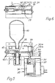
- Ausführungsbeispiele der Erfindung werden im folgenden anhand einer Zeichnung mit neun Figuren erläutert, woraus sich weitere vorteilhafte Einzelheiten ergeben können. Es zeigt:
- Figur 1
- eine erste Ausführungsform des Auslösers mit angebrachter CO2-Patrone bzw. CO2-Einwegflasche in der Position "betriebsbereit",
- Figur 2
- den Auslöser gemäß
Figur 1 in der inFigur 1 mit A-A bezeichneten Schnittebene, - Figur 3
- den Auslöser gemäß
Figur 1 in einem Längsschnitt in Position "ausgelöst", - Figur 4
- den Auslöser gemäß
Figur 3 in einem Querschnitt in der Schnittebene A-A, - Figur 5
- eine zweite Ausführungsform des Auslösers, und zwar mit zusätzlicher Magnetauslösung in der Position "Bereitschaft",
- Figur 6
- den Auslöser gemäß
Figur 5 in einem Querschnitt, - Figur 7
- den Auslöser gemäß
Figur 5 , jedoch in der Position "ausgelöst" in einem Längsschnitt, - Figur 8
- einen Querschnitt durch den Auslöser gemäß
Figur 7 in der Schnittebene A-A und - Figur 9
- eine Einzelheit des Auslösers, ähnlich der ersten Ausführungsform in der Position und Darstellung gemäß
Figur 4 , nämlich die Arretierungselemente in der Aufnahmebohrung. - In den
Figuren 1 bis 4 ist mit 1 ein Montageblock bezeichnet, aus dem eine Bohrung 2 für einen Anstechbolzen 3, eine Gewindebohrung 4 für einen Spannmechanismus 5 konzentrisch zu der Bohrung 2 bzw. dem Anstechbolzen 3 ausgeformt sind. An einem inFigur 1 unteren Ende des Spannmechanismus befindet sich eine Stellschraube 6, mit der eine Spannfeder 7 gespannt werden kann, die sich an einem Flansch 8 des Anstechbolzens 3 abstützt, um diesen in Richtung auf eine Anschlußöffnung 9 in dem Montageblock zu drücken, die eine CO2-Patrone aufnimmt. Zum Anstechen eines nicht bezeichneten Verschlußabschnitts der CO2-Patrone ist der Anstechbolzen 3 mit einer Anstechnadel 11 versehen. - Die Bohrung 2 für den Anstechbolzen bildet einen Druckraum, der mit einer Querbohrung 12 in Verbindung steht, in der ein Kolben 13 einer Anzeigeeinrichtung 14 verschiebbar gelagert ist, sowie mit einem nicht bezeichneten Druckmittelkanal.
- Der Anstechbolzen 3 mit der Anstechnadel 11, der Spannmechanismus 5 des Anstechbolzens, die Anschlußöffnung für die CO2-Patrone und die Anzeigeeinrichtung 14 gehören zum Stand der Technik und brauchen daher nicht detailliert beschrieben zu werden.
- In den
Figuren 1 und 2 ist der Auslöser in seiner Position "betriebsbereit" dargestellt. Zur Verriegelung weist der Anstechbolzen 3 eine umlaufende Nut 15 mit schrägen bzw. konischen Seitenwänden 16, 17 auf, in welche ein Arretierungselement in Form einer Kugel 20 eingreifen kann. Zur Aufnahme einer Reihe von aneinanderstoßenden Arretierungselementen ist aus dem Montageblock quer zu dem Anstechbolzen 3, und zwar zu dessen Nut in der Position "betriebsbereit" eine Aufnahmebohrung 18 ausgeformt, die zumindest an ihrem der Nut 1 5 zugewandten Ende offen ist und in der vorliegenden Ausführungsform auch an ihrem entgegengesetzten Ende an dem Montageblock offen sein kann, beispielsweise um die Arretierungselemente in die Aufnahmebohrung einzuführen, wonach das Ende durch eine flache Abdeckung 19 verschlossen werden kann. Die Arretierungselemente bestehen im einzelnen in der in denFiguren 1 bis 4 gezeigten Ausführungsform aus fünf Kugeln 20 - 24 und einem Zylinderstift 25, dessen nicht bezeichnete Längsachse in der ebenfalls nicht bezeichneten Längsachse der Aufnahmebohrung 18 liegt. Speziell befindet sich der Zylinderstift 25 zwischen der Kugel 20, die als äußere Kugel der Reihe in die Nut 15 des Anstechbolzens 3 eingreifen kann, und der Kugel 21 der in Reihe angeordneten Kugeln. - Wie inFigur 9 gezeigt, in der eine im Prinzip gleiche Anordnung der Arretierungselemente jedoch in einer Position "ausgelöst" dargestellt sind, kann zwischen der äußeren Kugel 20 und dem Zylinderstift 25 ein O-Ring 26 in der Aufnahmebohrung 18 angeordnet sein, um die Bohrung 2 für den Anstechbolzen gegenüber der Umgebung der Aufnahmebohrung 18 abzuschließen. - In der Position "betriebsbereit" stoßen die Arretierungselemente, nämlich die Kugeln 20 - 24 und der Zylinderstift 25 zentriert in der Längsachse der Aufnahmebohrung 18 aneinander an, wobei die äußere Kugel 20 in der Nut 15 liegt und die entgegengesetzte äußere Kugel 24 über einen O-Ring 27 an die Abdeckung 19 drückt. Die zentrierte Reihe Arretierungselemente hat eine größere Längsausdehnung als die Anordnung der Arretierungselemente in der Position "ausgelöst".
- Damit die Nut 1 5 zum Auslösen des Auslösers von der äußeren Kugel 20 freigegeben werden kann, weist die Aufnahmebohrung 18 eine seitliche Ausnehmung 28 auf, siehe
Figur 9 , die durch ein federnd nachgiebiges Wandelement in Form einer Scheibe 29, die unter dem Druck einer z.B. inFigur 2 angedeuteten Feder 30 steht, so daß die Scheibe 29 in Richtung auf die Achse der Aufnahmebohrung 18 gedrückt wird. Die Scheibe 29 und die Feder 30 sind in einer hohlen Scheiben- und Federaufnahme 31 in dem Montageblock 1 angeordnet, sieheFigur 9 . Auf der zu der Scheiben- und Federaufnahme 31 gegenüberliegenden Seite der Aufnahmebohrung 18 weist der Montageblock eine Querbohrung 32 auf, die sich von außen quer zu der Aufnahmebohrung 18 erstreckt und in der ein Auslösebolzen 33 verschiebbar gelagert ist. Der Auslösebolzen kann außen mit einem manuellen Betätigungselement in Verbindung stehen, welches in der Zeichnung nicht dargestellt ist. - Zum Auslösen des Auslösers, bei dem die Anstechnadeln 11 unter dem Druck der Spannfeder 7 in die CO2-Patrone 10 stechen soll, wird der Auslösebolzen 33 in die in den
Figuren 4 und9 gezeigte Stellung eingedrückt, in welcher der Auslösebolzen 33 die Kugeln 22 und 23 der Arretierungselemente 20 - 25 in die seitliche Ausnehmung 28 bis in die inFigur 9 gezeigte Lage unter die beidseitig angrenzenden Kugeln 21, 22 drückt, wodurch sich die Erstreckung der Anordnung der Arretierungselemente in der Aufnahmebohrung 18 in Richtung deren nicht bezeichneter Längsachse verkürzt, wodurch in der Aufnahmebohrung Raum freigegeben wird. In diesen Raum kann die äußere Kugel 20 unter der Wirkung der Spannfeder 7 aus der Nut 15 gleiten bzw. rollen, wie inFiguren 3, 4 ,9 dargestellt. InFigur 3 ist in der Position "ausgelöst" die Anstechnadel 11 in die CO2-Patrone 10 gestoßen, so daß aus der CO2-Patrone CO2 in die Bohrung 2 strömen kann. - Das ausströmende CO2 kann ein nicht dargestelltes integriertes Ventil, z.B. ein Vorrangventil oder ein Alarm- oder Lüftungsventil einer Rauch- und Wärmeabzugsanlage betätigen.
- Die Position "ausgelöst" wird mit der Anzeigeeinrichtung 14 infolge Verschiebung deren Kolbens 13 in der Querbohrung 12 angezeigt.
- Wenn der Anstechbolzen 3 in seiner Bohrung mit der Stellschraube 6 zurückgezogen wird, so daß die Anstechnadel 11 aus der CO2 -Patrone 10 gelangt, kann die Nut 1 5 mit der nicht bezeichneten Längsachse der Aufnahmebohrung 18 wieder fluchten, und die äußere Kugel 20 in die Nut 15 gelangen. Sie wird dadurch selbsttätig in die Nut gestoßen, daß die aus der Aufnahmebohrung 18 teilweise herausgedrückten Kugeln 22, 23 durch die Scheibe 29 infolge der Kraft der Feder 30 vollständig in die Aufnahmebohrung 18 zurückgedrückt werden, so daß alle Arretierungselemente 20 - 25 zentriert in einer Reihe liegen, die sich von der Abdeckung 1 9 bis in die Nut 15 erstreckt. Auch wenn die Vorspannkraft der Spannfeder 7 wieder erhöht wird, bleibt der Anstechbolzen 3 in seiner in
Figur 1 dargestellten Lage, da die äußere Kugel 20 an der Seitenwand 17 bzw. Fläche der Nut 15 anliegt und die Kugeln 22, 23 durch die an der Scheibe 29 angreifende Feder 30 in ihrer Stellung gehalten werden. Der Auslöser ist damit wieder betriebsbereit. - Die in den
Figuren 5 bis 8 dargestellte zweite Ausführungsform mit einem zusätzlichen elektromagnetischen Betätigungselement ist grundsätzlich wie die oben beschriebene Ausführungsform aufgebaut, bei der der Auslösebolzen mit einem manuellen Betätigungselement in Verbindung steht. Gleiche Teile sind daher mit gleichen Bezugszeichen versehen. Auch die Wirkung der zweiten Ausführungsform des Auslösers ist die gleiche wie die der ersten Ausführungsform, abgesehen von der zusätzlichen elektromagnetischen Betätigungsart. - In den
Figuren 5 und7 , in denen die zweite Ausführungsform in der Position "betriebsbereit" bzw. in der Position "ausgelöst" dargestellt ist, ist zur Betätigung des Auslösebolzens 34, das allgemein mit 35 bezeichnete elektromagnetische Betätigungselement vorgesehen, welches im wesentlichen einen Elektromagneten 36, welcher einen Magnetstößel 37 zwischen einer zurückgezogenen Stellung, sieheFigur 5 , und einer vorgeschobenen Stellung, sieheFigur 7 , einstellen kann. - In der zweiten Ausführungsform des Auslösers mit dieser Magnetauslösung gehören zu der Reihe Arretierungselemente weitere Kugeln, die mit 38 - 41 bezeichnet sind, entsprechend der größeren Länge der Aufnahmebohrung 42 in dem verlängerten Montageblock, an dem das elektromagnetische Betätigungselement 35 neben einem nicht dargestellten manuellen Betätigungselement angebracht ist. Der mit dem elektromagnetischen Betätigungselement 35 betätigbare Auslösebolzen 34 und der mit dem manuellen Betätigungselement betätigbare Auslösebolzen 33 sind um 90° gegeneinander verdreht in dem Montageblock 43 angeordnet.
- In der Position "Betriebsbereitschaft", die in den
Figuren 5 und 6 dargestellt ist, ist keine der Kugeln 22, 23, 39, 40 aus der Reihe Arretierungselemente gedrückt, weil der Auslösebolzen 34 von dem Magnetstößel 37 unbeeinflußt in seiner Ausgangsstellung ist und auch der Auslösebolzen 33 nicht betätigt ist. Somit liegt die äußere Kugel 20 wiederum in der Nut 15 des Anstechbolzens 3. - Hingegen werden gemäß den
Figuren 7 und 8 , wenn der Magnetstößel 37 den Auslösebolzen 34 hochdrückt, die Kugeln 39, 40 aus der Aufnahmebohrung 42 entgegen der mit der Feder 30a belasteten Scheibe 29a teilweise herausgedrückt und die äußere Kugel 20 kann aus der Nut 15 heraus den Abstechbolzen freigeben. - Zur weiteren Funktion der in den
Figuren 5 bis 8 gezeigten Ausführungsform, insbesondere bei manueller Betätigung, kann auf die erste Ausführungsform gemäß denFiguren 1 bis 4 und9 verwiesen werden. -
- 1
- Montageblock
- 2
- Bohrung für Anstechbolzen
- 3
- Anstechbolzen
- 4
- Gewindebohrung für Spannmechanismus
- 5
- Spannmechanismus
- 6
- Stellschraube
- 7
- Spannfeder
- 8
- Flansch
- 9
- Anschlußöffnung
- 10
- CO2-Patrone
- 11
- Anstechnadel (Anstechspitze)
- 12
- Querbohrung
- 13
- Kolben
- 14
- Anzeigeeinrichtung
- 15
- Nut
- 16
- Seitenwand
- 17
- Seitenwand
- 18
- Aufnahmebohrung
- 19
- flache Abdeckung
- 20
- Kugel (äußere)
- 21
- Kugel Arretierungselemente
- 22
- Kugel
- 23
- Kugel
- 24
- Kugel (entgegengesetzt äußere)
- 25
- Zylinderstift
- 26
- O-Ring
- 27
- O-Ring
- 28
- seitliche Ausnehmung
- 29
- Scheibe
- 29a
- Scheibe
- 30
- Feder
- 30a
- Feder
- 31
- Scheiben- und Federaufnahme
- 32
- Querbohrung
- 33
- Auslösebolzen
- 34
- Auslösebolzen
- 35
- elektromagnetisches Betätigungselement
- 36
- Elektromagnet
- 37
- Magnetstößel
- 38
- Kugel
- 39
- Kugel Arretierungselemente
- 40
- Kugel
- 41
- Kugel
- 42
- Aufnahmebohrung
- 43
- Montageblock
- 44
- flache Abdeckung
Claims (11)
- Auslöser eines Druckmittelspeichers, insbesondere einer CO2-Einwegflasche (10), mit einem mit einer Spannfeder (7) spannbaren Anstechbolzen (3), der an einem Ende gegenüber einem Verschlussabschnitt des Druckmittelspeichers eine Anstechspitze (11) trägt, sowie mit einer lösbaren Arretierung des Anstechbolzens (3),
wobei die Arretierung eine Aufnahmebohrung (18, 42) aufweist, in der eine Reihe aneinander stoßender Arretierungselemente (20 - 25, 38 - 41) einschließlich Kugeln (20 - 24, 38 - 41) aufgenommen sind, wobei die Aufnahmebohrung (18, 42) quer zu dem Anstechbolzen (3) angeordnet ist , und zwar quer zu einer Ausformung (15) in dem Anstechbolzen (3) in betriebsbereiter Position, in der eine Kugel (20) in die Ausformung (15) eingreift, wobei in die Aufnahmebohrung (18, 42) eine Querbohrung (32) mündet, in der ein Auslösebolzen (33, 34) verschiebbar ist, wobei die Aufnahmebohrung (18, 42) an einer der Querbohrung (32) gegenüberliegenden Stelle durchbrochen ist und durch ein federnd nachgiebiges Wandelement (29, 29a) begrenzt ist und wobei wenigstens eine der Kugeln (22, 23, 39, 40) zwischen dem Auslösebolzen (33, 34) und dem federnd nachgiebigen Wandelement (29, 30; 29a, 30a) liegt und somit durch den Auslösebolzen (33, 34) aus einer in der Aufnahmebohrung (18, 42) zentrierten Lage federnd herausdrückbar ist,
dadurch gekennzeichnet,
dass wenigstens zwei Kugeln (22, 23; 39, 40) durch den Auslösebolzen (33, 34) aus ihrer in der Aufnahmebohrung (18, 42) zentrierten Lage federnd herausdrückbar sind. - Auslöser nach Anspruch 1,
dadurch gekennzeichnet,
dass eine Nut (15) als Ausformung des Anstechbolzens (3) abgeschrägte bzw. konische Seitenwände (16, 17) aufweist, an die die eine der Kugeln (20) in betriebsbereiter Position des Anstechbolzens (3) anstößt. - Auslöser nach Anspruch 2,
dadurch gekennzeichnet,
dass in der Aufnahmebohrung (18) ein Zylinderstift (25) als eines der Arretierungselemente zwischen der Kugel (20) an der Nut (15) des Anstechbolzens (3) und einer der bis zu dem federnd nachgiebigen Wandelement (29, 29a) angeordneten Kugeln (21 - 24, 38, 39) vorgesehen ist. - Auslöser nach einem der Ansprüche 1 bis 3,
dadurch gekennzeichnet,
dass das federnd nachgiebige Wandelement (29, 29a) eine Scheibe ist, die durch eine Feder (30, 30a) gegen die Kugeln (22, 23; 39, 40) gedrückt ist. - Auslöser nach einem der vorangehenden Ansprüche,
dadurch gekennzeichnet,
dass der Auslösebolzen (34) mit einem elektromagnetischen Betätigungselement (35) in Verbindung steht. - Auslöser nach einem der Ansprüche 1 bis 6,
gekennzeichnet durch
ein manuelles Betätigungselement, welches mit dem Auslösebolzen (33) verbunden ist. - Auslöser nach einem der Ansprüche 1 bis 6,
dadurch gekennzeichnet,
dass er wenigstens einen Montageblock (1, 43) umfasst, in dem die Aufnahmebohrung (18, 42) mit der Querbohrung (32) für den Auslösebolzen (33, 34) sowie mit einer Scheiben- und Federaufnahme (31), eine den Anstechbolzen (3) aufnehmende Bohrung (2) mit einer Anschlussöffnung (9) für den Druckmittelspeicher, eine Gewindebohrung (4) für einen Spannmechanismus (5) sowie ein Druckmittelkanal ausgeformt sind. - Auslöser nach einem der Ansprüche 5 bis 7,
dadurch gekennzeichnet,
dass das elektromagnetische Betätigungselement (35) außen an einem Montageblock (1, 43) angebracht ist. - Auslöser nach einem der vorangehenden Ansprüche,
dadurch gekennzeichnet,
dass die Aufnahmebohrung (18, 42) und eine Scheiben- und Federaufnahme (31) nach außen durch eine flache Abdeckung (19) abgedeckt sind. - Auslöser nach einem der vorangehenden Ansprüche,
dadurch gekennzeichnet,
dass zwischen zwei Arretierungselementen (20, 25) in der Aufnahmebohrung (18, 42) ein abdichtender O-Ring (26) angeordnet ist. - Auslöser nach einem der Ansprüche 7 bis 11,
dadurch gekennzeichnet,
dass die Aufnahmebohrung (18, 42), die Scheiben- und Federaufnahme (31) sowie die Querbohrung (32) für den Auslösebolzen (33, 34) nach außen abgedichtet sind.
Priority Applications (1)
| Application Number | Priority Date | Filing Date | Title |
|---|---|---|---|
| PL06010896T PL1731826T3 (pl) | 2005-06-06 | 2006-05-27 | Wyzwalacz zbiornika ciśnieniowego |
Applications Claiming Priority (1)
| Application Number | Priority Date | Filing Date | Title |
|---|---|---|---|
| DE102005026177A DE102005026177B3 (de) | 2005-06-06 | 2005-06-06 | Auslöser eines Druckmittelspeichers, insbesondere einer CO2-Einwegflasche |
Publications (2)
| Publication Number | Publication Date |
|---|---|
| EP1731826A1 EP1731826A1 (de) | 2006-12-13 |
| EP1731826B1 true EP1731826B1 (de) | 2009-12-30 |
Family
ID=36910834
Family Applications (1)
| Application Number | Title | Priority Date | Filing Date |
|---|---|---|---|
| EP06010896A Active EP1731826B1 (de) | 2005-06-06 | 2006-05-27 | Auslöser eines Druckmittelspeichers |
Country Status (4)
| Country | Link |
|---|---|
| EP (1) | EP1731826B1 (de) |
| AT (1) | ATE453830T1 (de) |
| DE (2) | DE102005026177B3 (de) |
| PL (1) | PL1731826T3 (de) |
Family Cites Families (12)
| Publication number | Priority date | Publication date | Assignee | Title |
|---|---|---|---|---|
| GB1319549A (en) * | 1969-12-05 | 1973-06-06 | Gen Motors Corp | Sensor and trigger mechanism |
| DE2434049C3 (de) * | 1974-07-16 | 1980-03-27 | Josef 4815 Schloss Holte Fortmeier | Auslösevorrichtung für durch gasförmige Druckmedien steuerbare Anlagen zum Öffnen und Schließen von Lichtkuppeln, Rauchabzugsklappen o.dgl |
| CH643462A5 (en) * | 1980-03-20 | 1984-06-15 | Sulzer Ag | Gas cylinder valve for fire-fighting equipment |
| DE3032791A1 (de) * | 1980-08-30 | 1982-04-15 | Dynamit Nobel Ag, 5210 Troisdorf | Vorrichtung zur ausloesung eines schlagbolzens |
| DE8102639U1 (de) * | 1981-02-03 | 1981-07-09 | Fortmeier, Josef, 4815 Schloss Holte | Vorrichtung zum oeffnen eines druckmedienbehaelters |
| DE8326617U1 (de) | 1983-09-16 | 1984-12-13 | Fa. Josef Fortmeier, 4815 Schloß Holte | Vorrichtung zum oeffnen von mindestens zwei druckgaspatronen |
| DE3429178A1 (de) * | 1984-08-08 | 1986-02-20 | Josef 4815 Schloss Holte Fortmeier | Oeffnungsvorrichtung fuer rauch- und waermeabzugsklappen |
| DE3606561A1 (de) * | 1986-02-28 | 1987-09-03 | Colt Int Holdings | Vorrichtung zur pneumatischen zwangsbetaetigung von lueftungsklappen |
| DE3627727C1 (en) * | 1986-08-16 | 1987-11-05 | Adolf Brinkmann Gmbh & Co Kg | Piercing appliance for gas bottles |
| DE3700616A1 (de) * | 1987-01-10 | 1988-07-21 | Autoflug Gmbh | Gasflasche mit ausloesevorrichtung |
| DE3731247A1 (de) * | 1987-09-17 | 1989-03-30 | Colt Int Holdings | Vorrichtung zur zwangsbetaetigung von insbesondere lueftungsklappen |
| DE10121211B4 (de) * | 2001-04-30 | 2004-04-29 | Grasl, Andreas, Ing. | Thermische Auslöse- und Ventileinrichtung für Druckgaspatronen, insbesondere für Rauch- und Wärmeabzugsanlagen |
-
2005
- 2005-06-06 DE DE102005026177A patent/DE102005026177B3/de not_active Expired - Fee Related
-
2006
- 2006-05-27 AT AT06010896T patent/ATE453830T1/de active
- 2006-05-27 PL PL06010896T patent/PL1731826T3/pl unknown
- 2006-05-27 EP EP06010896A patent/EP1731826B1/de active Active
- 2006-05-27 DE DE502006005766T patent/DE502006005766D1/de active Active
Also Published As
| Publication number | Publication date |
|---|---|
| EP1731826A1 (de) | 2006-12-13 |
| PL1731826T3 (pl) | 2010-04-30 |
| DE102005026177B3 (de) | 2007-07-26 |
| ATE453830T1 (de) | 2010-01-15 |
| DE502006005766D1 (de) | 2010-02-11 |
Similar Documents
| Publication | Publication Date | Title |
|---|---|---|
| DE3510098C2 (de) | Pyrotechnischer Schieber | |
| DE4302798C1 (de) | Ventileinrichtung zum Entlüften von Druckgiessformen | |
| DE69208435T2 (de) | Druckflüssigkeitszylinder mit Druckübersetzer | |
| DE2924707C2 (de) | ||
| DE1576168B2 (de) | Schaltvorrichtung fuer einen am zylinderkopf eines druckmittelbetaetigten kolbenmotors angebrachten end schalter | |
| DE202007006631U1 (de) | Vorrichtung zur Steuerung einer Gas-Hochdruck-Feuerlöschanlage | |
| DE1576088A1 (de) | Schnellentlastungsventil fuer hydraulische Kraftzylinder | |
| DE2750472C2 (de) | ||
| EP2053300A1 (de) | Einleitungsverteiler | |
| EP3478995A1 (de) | Tankventil | |
| EP0334924A1 (de) | Verriegelbarer hydraulikzylinder | |
| WO2018050823A9 (de) | Anschlussadapter, insbesondere für klimaanlagen | |
| DE4404467C2 (de) | Hydraulischer Türfeststeller für Kraftwagentüren | |
| EP1511954B1 (de) | Einschraubventil | |
| DE102007007645B3 (de) | Ventil mit Schaltstellungsverriegelung | |
| EP1654464A1 (de) | Vorrichtung zum dämpfen von druckstössen | |
| DE3239930A1 (de) | Hydraulisch steuerbares sperrventil, insbesondere fuer die rohrbruchsicherung | |
| DE2821588A1 (de) | Ueberdruckventil | |
| EP0066734B1 (de) | Ausblas-Einrichtung für Ausstoss- und Ablaufrohre von U-Booten | |
| DE10121211B4 (de) | Thermische Auslöse- und Ventileinrichtung für Druckgaspatronen, insbesondere für Rauch- und Wärmeabzugsanlagen | |
| EP0842102B1 (de) | Blasvorrichtung mit aussenliegender ventileinheit | |
| DE102005026177B3 (de) | Auslöser eines Druckmittelspeichers, insbesondere einer CO2-Einwegflasche | |
| DE3018920A1 (de) | Verriegelung fuer druckzylinderkolben | |
| DE69121256T2 (de) | Ventil für Druckluftwaffen | |
| DE3516795A1 (de) | Schlauchbruchsicherungsvorrichtung |
Legal Events
| Date | Code | Title | Description |
|---|---|---|---|
| PUAI | Public reference made under article 153(3) epc to a published international application that has entered the european phase |
Free format text: ORIGINAL CODE: 0009012 |
|
| AK | Designated contracting states |
Kind code of ref document: A1 Designated state(s): AT BE BG CH CY CZ DE DK EE ES FI FR GB GR HU IE IS IT LI LT LU LV MC NL PL PT RO SE SI SK TR |
|
| AX | Request for extension of the european patent |
Extension state: AL BA HR MK YU |
|
| 17P | Request for examination filed |
Effective date: 20070613 |
|
| AKX | Designation fees paid |
Designated state(s): AT BE BG CH CY CZ DE DK EE ES FI FR GB GR HU IE IS IT LI LT LU LV MC NL PL PT RO SE SI SK TR |
|
| 17Q | First examination report despatched |
Effective date: 20081119 |
|
| GRAP | Despatch of communication of intention to grant a patent |
Free format text: ORIGINAL CODE: EPIDOSNIGR1 |
|
| GRAS | Grant fee paid |
Free format text: ORIGINAL CODE: EPIDOSNIGR3 |
|
| GRAA | (expected) grant |
Free format text: ORIGINAL CODE: 0009210 |
|
| AK | Designated contracting states |
Kind code of ref document: B1 Designated state(s): AT BE BG CH CY CZ DE DK EE ES FI FR GB GR HU IE IS IT LI LT LU LV MC NL PL PT RO SE SI SK TR |
|
| REG | Reference to a national code |
Ref country code: GB Ref legal event code: FG4D Free format text: NOT ENGLISH |
|
| REG | Reference to a national code |
Ref country code: CH Ref legal event code: EP |
|
| REG | Reference to a national code |
Ref country code: IE Ref legal event code: FG4D |
|
| REF | Corresponds to: |
Ref document number: 502006005766 Country of ref document: DE Date of ref document: 20100211 Kind code of ref document: P |
|
| PG25 | Lapsed in a contracting state [announced via postgrant information from national office to epo] |
Ref country code: LT Free format text: LAPSE BECAUSE OF FAILURE TO SUBMIT A TRANSLATION OF THE DESCRIPTION OR TO PAY THE FEE WITHIN THE PRESCRIBED TIME-LIMIT Effective date: 20091230 Ref country code: FI Free format text: LAPSE BECAUSE OF FAILURE TO SUBMIT A TRANSLATION OF THE DESCRIPTION OR TO PAY THE FEE WITHIN THE PRESCRIBED TIME-LIMIT Effective date: 20091230 Ref country code: SE Free format text: LAPSE BECAUSE OF FAILURE TO SUBMIT A TRANSLATION OF THE DESCRIPTION OR TO PAY THE FEE WITHIN THE PRESCRIBED TIME-LIMIT Effective date: 20091230 |
|
| REG | Reference to a national code |
Ref country code: PL Ref legal event code: T3 |
|
| LTIE | Lt: invalidation of european patent or patent extension |
Effective date: 20091230 |
|
| PG25 | Lapsed in a contracting state [announced via postgrant information from national office to epo] |
Ref country code: LV Free format text: LAPSE BECAUSE OF FAILURE TO SUBMIT A TRANSLATION OF THE DESCRIPTION OR TO PAY THE FEE WITHIN THE PRESCRIBED TIME-LIMIT Effective date: 20091230 Ref country code: SI Free format text: LAPSE BECAUSE OF FAILURE TO SUBMIT A TRANSLATION OF THE DESCRIPTION OR TO PAY THE FEE WITHIN THE PRESCRIBED TIME-LIMIT Effective date: 20091230 |
|
| REG | Reference to a national code |
Ref country code: IE Ref legal event code: FD4D |
|
| PG25 | Lapsed in a contracting state [announced via postgrant information from national office to epo] |
Ref country code: ES Free format text: LAPSE BECAUSE OF FAILURE TO SUBMIT A TRANSLATION OF THE DESCRIPTION OR TO PAY THE FEE WITHIN THE PRESCRIBED TIME-LIMIT Effective date: 20100410 Ref country code: IS Free format text: LAPSE BECAUSE OF FAILURE TO SUBMIT A TRANSLATION OF THE DESCRIPTION OR TO PAY THE FEE WITHIN THE PRESCRIBED TIME-LIMIT Effective date: 20100430 Ref country code: BG Free format text: LAPSE BECAUSE OF FAILURE TO SUBMIT A TRANSLATION OF THE DESCRIPTION OR TO PAY THE FEE WITHIN THE PRESCRIBED TIME-LIMIT Effective date: 20100330 Ref country code: EE Free format text: LAPSE BECAUSE OF FAILURE TO SUBMIT A TRANSLATION OF THE DESCRIPTION OR TO PAY THE FEE WITHIN THE PRESCRIBED TIME-LIMIT Effective date: 20091230 Ref country code: PT Free format text: LAPSE BECAUSE OF FAILURE TO SUBMIT A TRANSLATION OF THE DESCRIPTION OR TO PAY THE FEE WITHIN THE PRESCRIBED TIME-LIMIT Effective date: 20100430 Ref country code: RO Free format text: LAPSE BECAUSE OF FAILURE TO SUBMIT A TRANSLATION OF THE DESCRIPTION OR TO PAY THE FEE WITHIN THE PRESCRIBED TIME-LIMIT Effective date: 20091230 |
|
| PG25 | Lapsed in a contracting state [announced via postgrant information from national office to epo] |
Ref country code: SK Free format text: LAPSE BECAUSE OF FAILURE TO SUBMIT A TRANSLATION OF THE DESCRIPTION OR TO PAY THE FEE WITHIN THE PRESCRIBED TIME-LIMIT Effective date: 20091230 Ref country code: CZ Free format text: LAPSE BECAUSE OF FAILURE TO SUBMIT A TRANSLATION OF THE DESCRIPTION OR TO PAY THE FEE WITHIN THE PRESCRIBED TIME-LIMIT Effective date: 20091230 |
|
| PG25 | Lapsed in a contracting state [announced via postgrant information from national office to epo] |
Ref country code: IE Free format text: LAPSE BECAUSE OF FAILURE TO SUBMIT A TRANSLATION OF THE DESCRIPTION OR TO PAY THE FEE WITHIN THE PRESCRIBED TIME-LIMIT Effective date: 20091230 Ref country code: GR Free format text: LAPSE BECAUSE OF FAILURE TO SUBMIT A TRANSLATION OF THE DESCRIPTION OR TO PAY THE FEE WITHIN THE PRESCRIBED TIME-LIMIT Effective date: 20100331 Ref country code: CY Free format text: LAPSE BECAUSE OF FAILURE TO SUBMIT A TRANSLATION OF THE DESCRIPTION OR TO PAY THE FEE WITHIN THE PRESCRIBED TIME-LIMIT Effective date: 20091230 |
|
| PLBE | No opposition filed within time limit |
Free format text: ORIGINAL CODE: 0009261 |
|
| STAA | Information on the status of an ep patent application or granted ep patent |
Free format text: STATUS: NO OPPOSITION FILED WITHIN TIME LIMIT |
|
| BERE | Be: lapsed |
Owner name: GRASL, ANDREAS Effective date: 20100531 |
|
| 26N | No opposition filed |
Effective date: 20101001 |
|
| PG25 | Lapsed in a contracting state [announced via postgrant information from national office to epo] |
Ref country code: MC Free format text: LAPSE BECAUSE OF NON-PAYMENT OF DUE FEES Effective date: 20100531 |
|
| REG | Reference to a national code |
Ref country code: CH Ref legal event code: PL |
|
| PG25 | Lapsed in a contracting state [announced via postgrant information from national office to epo] |
Ref country code: DK Free format text: LAPSE BECAUSE OF FAILURE TO SUBMIT A TRANSLATION OF THE DESCRIPTION OR TO PAY THE FEE WITHIN THE PRESCRIBED TIME-LIMIT Effective date: 20091230 |
|
| PG25 | Lapsed in a contracting state [announced via postgrant information from national office to epo] |
Ref country code: LI Free format text: LAPSE BECAUSE OF NON-PAYMENT OF DUE FEES Effective date: 20100531 Ref country code: CH Free format text: LAPSE BECAUSE OF NON-PAYMENT OF DUE FEES Effective date: 20100531 |
|
| PG25 | Lapsed in a contracting state [announced via postgrant information from national office to epo] |
Ref country code: BE Free format text: LAPSE BECAUSE OF NON-PAYMENT OF DUE FEES Effective date: 20100531 |
|
| PG25 | Lapsed in a contracting state [announced via postgrant information from national office to epo] |
Ref country code: HU Free format text: LAPSE BECAUSE OF FAILURE TO SUBMIT A TRANSLATION OF THE DESCRIPTION OR TO PAY THE FEE WITHIN THE PRESCRIBED TIME-LIMIT Effective date: 20100701 Ref country code: LU Free format text: LAPSE BECAUSE OF NON-PAYMENT OF DUE FEES Effective date: 20100527 |
|
| PG25 | Lapsed in a contracting state [announced via postgrant information from national office to epo] |
Ref country code: TR Free format text: LAPSE BECAUSE OF FAILURE TO SUBMIT A TRANSLATION OF THE DESCRIPTION OR TO PAY THE FEE WITHIN THE PRESCRIBED TIME-LIMIT Effective date: 20091230 |
|
| REG | Reference to a national code |
Ref country code: FR Ref legal event code: PLFP Year of fee payment: 11 |
|
| REG | Reference to a national code |
Ref country code: FR Ref legal event code: PLFP Year of fee payment: 12 |
|
| PGFP | Annual fee paid to national office [announced via postgrant information from national office to epo] |
Ref country code: NL Payment date: 20170525 Year of fee payment: 12 |
|
| REG | Reference to a national code |
Ref country code: DE Ref legal event code: R082 Ref document number: 502006005766 Country of ref document: DE Representative=s name: KEIL & SCHAAFHAUSEN PATENTANWAELTE PARTGMBB, DE Ref country code: DE Ref legal event code: R082 Ref document number: 502006005766 Country of ref document: DE Representative=s name: KEIL & SCHAAFHAUSEN PATENT- UND RECHTSANWAELTE, DE |
|
| REG | Reference to a national code |
Ref country code: FR Ref legal event code: PLFP Year of fee payment: 13 |
|
| PGFP | Annual fee paid to national office [announced via postgrant information from national office to epo] |
Ref country code: PL Payment date: 20180502 Year of fee payment: 13 |
|
| PGFP | Annual fee paid to national office [announced via postgrant information from national office to epo] |
Ref country code: GB Payment date: 20180523 Year of fee payment: 13 |
|
| REG | Reference to a national code |
Ref country code: NL Ref legal event code: MM Effective date: 20180601 |
|
| PG25 | Lapsed in a contracting state [announced via postgrant information from national office to epo] |
Ref country code: NL Free format text: LAPSE BECAUSE OF NON-PAYMENT OF DUE FEES Effective date: 20180601 |
|
| GBPC | Gb: european patent ceased through non-payment of renewal fee |
Effective date: 20190527 |
|
| PG25 | Lapsed in a contracting state [announced via postgrant information from national office to epo] |
Ref country code: GB Free format text: LAPSE BECAUSE OF NON-PAYMENT OF DUE FEES Effective date: 20190527 Ref country code: IT Free format text: LAPSE BECAUSE OF NON-PAYMENT OF DUE FEES Effective date: 20190527 |
|
| PG25 | Lapsed in a contracting state [announced via postgrant information from national office to epo] |
Ref country code: PL Free format text: LAPSE BECAUSE OF NON-PAYMENT OF DUE FEES Effective date: 20190527 |
|
| PGFP | Annual fee paid to national office [announced via postgrant information from national office to epo] |
Ref country code: FR Payment date: 20220523 Year of fee payment: 17 |
|
| PG25 | Lapsed in a contracting state [announced via postgrant information from national office to epo] |
Ref country code: FR Free format text: LAPSE BECAUSE OF NON-PAYMENT OF DUE FEES Effective date: 20230531 |
|
| PGFP | Annual fee paid to national office [announced via postgrant information from national office to epo] |
Ref country code: DE Payment date: 20240528 Year of fee payment: 19 |
|
| PGFP | Annual fee paid to national office [announced via postgrant information from national office to epo] |
Ref country code: AT Payment date: 20250519 Year of fee payment: 20 |
|
| REG | Reference to a national code |
Ref country code: DE Ref legal event code: R119 Ref document number: 502006005766 Country of ref document: DE |
|
| PG25 | Lapsed in a contracting state [announced via postgrant information from national office to epo] |
Ref country code: DE Free format text: LAPSE BECAUSE OF NON-PAYMENT OF DUE FEES Effective date: 20251202 |