EP1731237A2 - Metal sheet working machine - Google Patents
Metal sheet working machine Download PDFInfo
- Publication number
- EP1731237A2 EP1731237A2 EP06007822A EP06007822A EP1731237A2 EP 1731237 A2 EP1731237 A2 EP 1731237A2 EP 06007822 A EP06007822 A EP 06007822A EP 06007822 A EP06007822 A EP 06007822A EP 1731237 A2 EP1731237 A2 EP 1731237A2
- Authority
- EP
- European Patent Office
- Prior art keywords
- sheet metal
- working machine
- tool
- metal working
- bending
- Prior art date
- Legal status (The legal status is an assumption and is not a legal conclusion. Google has not performed a legal analysis and makes no representation as to the accuracy of the status listed.)
- Granted
Links
Images


Classifications
-
- B—PERFORMING OPERATIONS; TRANSPORTING
- B21—MECHANICAL METAL-WORKING WITHOUT ESSENTIALLY REMOVING MATERIAL; PUNCHING METAL
- B21D—WORKING OR PROCESSING OF SHEET METAL OR METAL TUBES, RODS OR PROFILES WITHOUT ESSENTIALLY REMOVING MATERIAL; PUNCHING METAL
- B21D5/00—Bending sheet metal along straight lines, e.g. to form simple curves
- B21D5/02—Bending sheet metal along straight lines, e.g. to form simple curves on press brakes without making use of clamping means
Definitions
- the invention relates to a sheet metal working machine, with a table for receiving interchangeable bending dies, an over which can be raised and lowered disposed upper cheek for receiving replaceable punch and a movable in the machine direction stop device.
- Bent sheet metal parts which have both curves and bends, are no longer thinkable from modern designs.
- For the production of such bent sheet metal parts so far at least two different machines are needed, namely a press brake and a curler.
- the sheet metal part (workpiece) has to be transported back and forth several times between the machines. This is time consuming and costly.
- the sheet metal part must be repositioned each time in the machine.
- the DE 37 45 067 C2 discloses a plate bending machine according to the preamble of claim 1.
- the DE 32 08 851 A1 discloses a three-roll bending press with two lower rolls in a fixed position and an upper roll.
- the upper roller is reciprocable at both ends by means of steering joints actuated by two pairs of hydraulic pistons.
- the invention has for its object to provide a sheet metal working machine of the specified type, which is suitable sheet metal parts having bends and curves to produce efficiently.
- the advantages achieved by the invention are that the sheet metal bent part is no longer transported between two different machines and the sheet metal part usually has to be positioned only once in the machine according to the invention.
- the integration according to the invention of the tools necessary for the various processing steps, i. a Abkant- and curl into a machine, allows rapid production of bent sheet metal parts with high surface quality, which have both curves and folds.
- the advantageous embodiment described in claim 2 allows accurate monitoring of the rolling process. If both upper and lower tools are each equipped with a position transducer, the machine controller can detect slippage between the rollers and the bending part and as a result adjust the control of the machine, e.g. the pressure exerted by the upper cheek is changed.
- a further advantageous embodiment allows the curling of funnels.
- the upper beam is lowered obliquely, and the stop device has at least two attachment points, which are independently movable at least in width and depth.
- the further advantageous embodiment in claim 3 makes it possible to adjust the working width of the curl the sheet metal part.
- the rollers not frictional connected the movement of the sheet metal part is not orthogonal to the roller axes of the retractor.
- the claim 5 relates to a further advantageous embodiment.
- the height-adjustable stop table holds the stop device in constant contact with the workpiece. Thereby, an undesirable sagging of the sheet metal bent part by gravity can be prevented.
- this embodiment allows a change of the Einrollradien according to a predetermined program.
- the claim 6 describes a particularly advantageous embodiment.
- the stop device can act as a support if so high forces are necessary for deforming the sheet-metal bent part, that the slip between the rollers and the Bechbiegeteil becomes large, since by means of the gripper feed, in particular tensile forces can be transmitted from the drive of the stop device on the sheet metal bending part. If the stop device NC controlled, this allows a very accurate control of the rolling process.
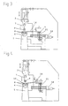
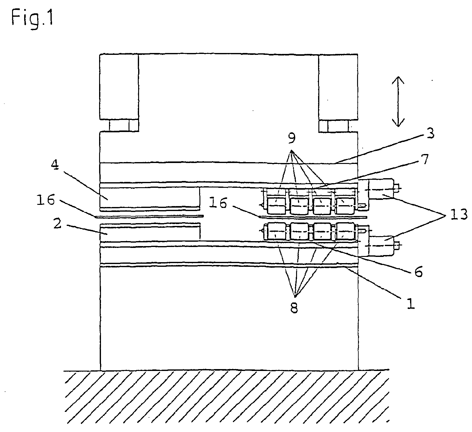
- FIG. 1 of the sheet metal working machine shows a table 1, on which a bending die 2 and the lower tool 6 a retractor are attached. Above this there is a raising and lowering upper cheek 3, on which a bending punch 4 are fastened over the bending die 2 and an upper tool 7 are suspended above the lower tool 6.
- the lower tool 6 and the upper tool 7 are rotationally driven by means of a geared motor 13.
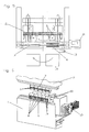
- FIG. 2 shows an embodiment in which behind the table 1, an NC-controlled longitudinal and height adjustable stop device 21 is located. It includes, inter alia, a table 5 and the usual drives such as 18.
- FIG. 2 shows the workpiece 16 located between the bending punch 4 and the bending die 2. Likewise, the receptacle for the replaceable punch 4 and the replaceable Biegematritze 2 can be seen. If the upper beam 3 is lowered, this causes a bending of the workpiece 16.
- FIG. 3 shows the embodiment from the other side. Here is the bending tool instead of the To see lower tool 6 and the upper tool 7 of the retractor.
- the lower tool 6 of the rolling device has two parallel rollers 8, which are rotatably mounted at right angles to the workpiece transport direction.
- the upper tool 7 located above has a roller 9, which is arranged rotatable parallel to the two lower rollers 8. It is also possible to equip the upper tool 7 with two rollers, in this case, only one roller is necessary on the lower tool 6.
- both lower tool 6 and upper tool 7 each have two rollers, and at least one tool 6 and / or 7 is pivotally connected to the table or the upper beam. In this embodiment, also S-bends can be produced in one operation.
- FIG. 4 shows a development in which the stop device 21 comprises a gripper 14.
- FIG. 5 shows a partially sectioned plan view. Shown is a movable stop device 21 with two stop tables 5, which are independently movable in the x direction, and a machine control 11, the table 1, the driven by means of geared motor 13 lower tool 6, the workpiece 16 and the Biegematritze 2. For alternating folding and Rounds of the workpiece must be moved between the individual steps only the stop tables 5 and the workpiece 16 are moved accordingly.
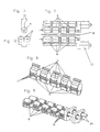
- FIG. 6 shows the preferred embodiment of the rolling-in device, in which the upper tool 7 has a modular construction.
- the individual, exchangeable modules 12 each comprise a roller 9 (see Fig. 8) which is rotatably supported by means of two bearing shafts 17.
- the modules 12 are held in the upper beam 3 by wedge and groove.
- the lower tool 6 is rotationally driven by means of the geared motor 13 and modular built up.
- the rollers 8 of the lower tool 6 are non-positively connected by jaw clutches.
- FIG. 7 shows the embodiment of the rolling-in device according to FIG. 1 in the frontal view.
- the lower tool 6 and the upper tool 7 are constructed modularly from rollers 8, 9 and rotationally driven with their own geared motor 13.
- FIG. 8 shows a detailed view of the modules 12 of the upper tool 7 in FIG. 6.
- Figure 9 shows the modules of the lower tool 6 in Fig. 6.
- the lower rollers 8 can be non-positively connected by means of jaw clutches.
- FIG. 10 shows a section through the lower tool 6 in FIG. 6.
- the lower rollers 8 are rotatably mounted on bearing shafts 19.
- the cross member 23 has recesses so that the lower rollers 8 are rotatable.
- FIGS. 11 and 12 show side views of the upper tool 7 and the lower tool 6.
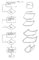
- FIG. 13 shows the workflow for producing an exemplary bent sheet metal part according to the prior art.
- FIG. 14 shows the workflow for producing a structurally identical bent sheet metal part by means of the sheet metal working machine according to the invention.
- the comparison of the two workflows shows that a workflow is achieved with the sheet metal working machine according to the invention, which manages with a significantly reduced number of steps.
Landscapes
- Engineering & Computer Science (AREA)
- Mechanical Engineering (AREA)
- Bending Of Plates, Rods, And Pipes (AREA)
- Press Drives And Press Lines (AREA)
- Advancing Webs (AREA)
- Soil Working Implements (AREA)
Abstract
Eine Blechbearbeitungsmaschine zur Verformung von Blechbiegeteilen sowohl durch Abkanten als auch durch Runden umfasst einen Tisch (1) mit Biegematrizen (2), eine Oberwange (3) mit auswechselbaren Biegestempeln (4) sowie ein neben der Aufnahme für die Biegematritzen auswechselbar angeordnetes Unterwerkzeug (6) aus drehbaren unteren Rollen (8) und ein darüber an der Oberwange neben der Aufnahme für die Biegestempel auswechselbar befestigtes Oberwerkzeug (7) mit einer drehbaren oberen Rolle (9).
Description
Die Erfindung betrifft eine Blechbearbeitungsmaschine, mit einem Tisch zur Aufnahme auswechselbarer Biegematrizen, einer darüber heb- und senkbar angeordneten Oberwange zur Aufnahme auswechselbarer Biegestempel und einer in Bearbeitungsrichtung verfahrbaren Anschlagvorrichtung.The invention relates to a sheet metal working machine, with a table for receiving interchangeable bending dies, an over which can be raised and lowered disposed upper cheek for receiving replaceable punch and a movable in the machine direction stop device.
Blechbiegeteile, die sowohl Rundungen als auch Abkantungen aufweisen, sind aus modernen Konstruktionen nicht mehr wegdenkbar. Für die Herstellung solcher Blechbiegeteile werden bisher mindestens zwei verschiedene Maschinen benötigt, nämlich eine Abkantpresse und eine Einrollmaschine. Je nach Komplexität der Umformung muss das Blechbiegeteil (Werkstück) mehrfach zwischen den Maschinen hin und her tranportiert werden. Dies ist zeitaufwendig und kostenintensiv. Außerdem muss das Blechbiegeteil jedesmal in der Maschine neu positioniert werden.Bent sheet metal parts, which have both curves and bends, are no longer thinkable from modern designs. For the production of such bent sheet metal parts so far at least two different machines are needed, namely a press brake and a curler. Depending on the complexity of the forming, the sheet metal part (workpiece) has to be transported back and forth several times between the machines. This is time consuming and costly. In addition, the sheet metal part must be repositioned each time in the machine.
Eine weitere Möglichkeit besteht darin, das Blechbiegeteil durch Vielfachabkantungen mittels einer Abkantpresse zu runden. Die Rundung wird dementsprechend durch einen Polygonzug angenähert. Zwar muss das Blechbiegeteil in der Maschine nur einmal positioniert werden und auch der Transport zwischen den unterschiedlichen Maschinen entfällt, doch die Vielfachabkantungen sind auf polierten und geschliffenen Oberflächen deutlich zu erkennen, was häufig unerwünscht ist. Darüberhinaus ist diese Methode sehr zeitaufwendig. Ein weiterer Nachteil dieses Verfahrens besteht darin, dass z.B. elliptische Formen nicht durch Vielfachabkantungen herstellbar sind.Another possibility is to round the sheet metal part by Mehrfachabkantungen means of a press brake. The rounding is accordingly approximated by a polygon. Although the sheet metal bending part only has to be positioned once in the machine and also eliminates the transport between the different machines, but the Mehrfachabkantungen are clearly visible on polished and ground surfaces, which is often undesirable. Moreover, this method is very time consuming. Another disadvantage of this method is that, for example, elliptical shapes can not be produced by multiple edging.
Die
Die
Der Erfindung liegt die Aufgabe zugrunde, eine Blechbearbeitungsmaschine der angegebenen Gattung zu schaffen, die geeignet ist Blechbiegeteile, die Abkantungen und Rundungen aufweisen, effizient zu fertigen.The invention has for its object to provide a sheet metal working machine of the specified type, which is suitable sheet metal parts having bends and curves to produce efficiently.
Diese Aufgabe ist durch eine Blechbearbeitungsmaschine mit den Merkmalen des Patentanspruches 1 gelöst.This object is achieved by a sheet metal working machine with the features of
Die mit der Erfindung erreichten Vorteile bestehen darin, dass das Blechbiegeteil nicht mehr zwischen zwei verschiedenen Maschinen transportiert werden und das Blechbiegeteil im Regelfall nur einmal in der erfindungsgemäßen Maschine positioniert werden muss. Die erfindungsgemäße Integration der für die verschiedenen Bearbeitungsschritte notwendigen Werkzeuge d.h. einer Abkant- und Einrollvorrichtung in eine Maschine, ermöglicht eine rasche Produktion von Blechbiegteilen mit hoher Oberflächengüte, die sowohl Rundungen als auch Abkantungen aufweisen.The advantages achieved by the invention are that the sheet metal bent part is no longer transported between two different machines and the sheet metal part usually has to be positioned only once in the machine according to the invention. The integration according to the invention of the tools necessary for the various processing steps, i. a Abkant- and curl into a machine, allows rapid production of bent sheet metal parts with high surface quality, which have both curves and folds.
Die in Anspruch 2 beschriebene vorteilhafte Ausgestaltung ermöglicht eine genaue Überwachung des Einrollvorgangs. Sind sowohl Ober- als auch das Unterwerkzeug mit je einem Wegmessgeber ausgestattet, kann die Maschinensteuerung Schlupf zwischen den Rollen und dem Biegeteil erkennen und als Folge daraus die Steuerung der Maschine anpassen, indem z.B. der durch die Oberwange ausgeübte Druck geändert wird.The advantageous embodiment described in
Eine weitere vorteilhafte Ausführungsform ermöglicht das Einrollen von Trichtern. Hierzu ist die Oberwange schräg absenkbar, und die Anschlagvorrichtung weist mindestens zwei Anschlagpunkte auf, die mindestens in der Breite und der Tiefe unabhängig voneinander verfahrbar sind.A further advantageous embodiment allows the curling of funnels. For this purpose, the upper beam is lowered obliquely, and the stop device has at least two attachment points, which are independently movable at least in width and depth.
Die weitere vorteilhafte Ausgestaltung in Patentanspruch 3 ermöglicht es, die Arbeitsbreite der Einrollvorrichtung dem Blechbiegeteil anzupassen. Werden die Rollen nicht kraftschlüssig verbunden, verläuft die Bewegung des Blechbiegeteils nicht orthogonal zu den Rollenachsen der Einrollvorrichtung.The further advantageous embodiment in
Im Anspruch 4 ist eine besonders vorteilhafte Art die Rollenmodule zu verbinden beschrieben. Klauenkupplungen und Hirtverzahnungen erlauben bei einfacher Kuppelbarkeit die Übertragung hoher Drehmomente.In
Der Patentanspruch 5 betrifft eine weitere vorteilhafte Ausführungsform. Der höhenverstellbare Anschlagtisch hält die Anschlagvorrichtung im ständigen Kontakt mit dem Werkstück. Dadurch kann ein unerwünschtes Durchhängen des Blechbiegeteils durch die Schwerkraft verhindert werden. Im Falle einer NC-Achsen gesteuerten Anschlagvorrichtung, welche mit der Maschinensteuerung verbunden ist, erlaubt diese Ausführungsform eine Änderung der Einrollradien nach einem vorgegebenen Programm.The
Der Anspruch 6 beschreibt eine besonders vorteilhafte Ausführungsform. Die Anschlagvorrichtung kann unterstützend wirken, wenn zum Verformen des Blechbiegeteils so hohe Kräfte notwendig sind, daß der Schlupf zwischen den Rollen und dem Bechbiegeteil groß wird, da mittels des Greifers Vorschub-, insbesondere Zugkräfte vom Antrieb der Anschlagvorrichtung auf das Blechbiegeteil übertragen werden können. Ist die Anschlagvorrichtung NC gesteuert, so ermöglicht dies ein sehr genaues Steuern des Einrollvorgangs.The
In der Zeichnung sind Ausführungsbeispiele einer erfindungsgemäßen Blechbearbeitungsmaschine und deren Einzelheiten schematisch dargestellt. Es zeigt:
- Fig. 1
- eine Frontansicht,
- Fig. 2
- eine Seitenansicht von links,
- Fig. 3
- eine erste Seitenansicht von rechts,
- Fig. 4
- eine weitere Ausführungsform in einer Seiteansicht von rechts,
- Fig. 5
- eine teilweise geschnittene Aufsicht,
- Fig. 6
- eine erste Auführungform einer Einrollvorrichtung,
- Fig. 7
- eine Frontansicht einer Einrollvorrichtung,
- Fig. 8
- ein modular aufgebautes Oberwerkzeug,
- Fig. 9
- ein modular aufgebautes Unterwerkzeug,
- Fig. 10
- einen Schnitt durch das Unterwerkzeug aus Fig. 9,
- Fig. 11
- eine Seitenansicht eines Oberwerkzeugs,
- Fig. 12
- eine Seitenansicht eines Unterwerkzeugs,
- Fig. 13
- einen Arbeitsablauf nach dem Stand der Technik,
- Fig. 14
- einen Arbeitsablauf an der erfindungsgemäßen Maschine.
- Fig. 1
- a front view,
- Fig. 2
- a side view from the left,
- Fig. 3
- a first side view from the right,
- Fig. 4
- another embodiment in a side view from the right,
- Fig. 5
- a partially sectioned top view,
- Fig. 6
- a first embodiment of a curling device,
- Fig. 7
- a front view of a curling device,
- Fig. 8
- a modular upper tool,
- Fig. 9
- a modular lower tool,
- Fig. 10
- a section through the lower tool of FIG. 9,
- Fig. 11
- a side view of an upper tool,
- Fig. 12
- a side view of a lower tool,
- Fig. 13
- a workflow according to the prior art,
- Fig. 14
- a workflow on the machine according to the invention.
Die in Fig. 1 dargestellte Ansicht der erfindungsgemäßen Blechbearbeitungsmaschine zeigt einen Tisch 1, auf dem eine Biegematritze 2 und das Unterwerkzeug 6 einer Einrollvorrichtung befestigt sind. Darüber befindet sich eine hebund senkbare Oberwange 3, an der ein Biegestempel 4 über der Biegematritze 2 und ein Oberwerkzeug 7 über dem Unterwerkzeug 6 hängend befestigt sind. Das Unterwerkzeug 6 und das Oberwerkzeug 7 sind mittels je eines Getriebemotors 13 drehangetrieben.The view shown in Fig. 1 of the sheet metal working machine according to the invention shows a table 1, on which a
Die Figuren 2 und 3 zeigen eine Ausführungsform, bei der sich hinter dem Tisch 1 eine NC-gesteuerte längs- und höhenverstellbare Anschlagvorrichtung 21 befindet. Sie umfaßt u.a. einen Tisch 5 und die üblichen Antriebe wie etwa 18. In der Figur 2 ist das zwischen Biegestempel 4 und Biegematrize 2 befindliche Werkstück 16 dargestellt. Ebenso ist die Aufnahme für den auswechselbaren Biegestempel 4 und die auswechselbare Biegematritze 2 zu erkennen. Wird die Oberwange 3 gesenkt, bewirkt dies eine Abkantung des Werkstücks 16. Die Figur 3 zeigt die Ausführungsform von der anderen Seite. Hier ist anstelle des Biegewerkzeugs das Unterwerkzeug 6 und das Oberwerkzeug 7 der Einrollvorrichtung zu sehen. Das Unterwerkzeug 6 der Einrollvorrichtung hat zwei parallele Rollen 8, welche rechtwinklig zu Werkstücktransportrichtung drehbar gelagert sind. Das darüber befindliche Oberwerkzeug 7 weist eine Rolle 9 auf, welche parallel zu den beiden unteren Rollen 8 drehbar angeordnet ist. Es ist auch möglich, das Oberwerkzeug 7 mit zwei Rollen auszustatten, in diesem Fall ist am Unterwerkzeug 6 nur eine Rolle notwendig. In einer anderen Ausführungsform weisen sowohl Unterwerkzeug 6 als auch Oberwerkzeug 7 je zwei Rollen auf, und mindestens ein Werkzeug 6 und/oder 7 ist schwenkbar mit dem Tisch bzw. der Oberwange verbunden. In dieser Ausführungsform können auch S-Biegungen in einem Arbeitsgang hergestellt werden.Figures 2 and 3 show an embodiment in which behind the table 1, an NC-controlled longitudinal and height
In der Figur 4 ist eine Weiterbildung gezeigt, in welcher die Anschlagvorrichtung 21 einen Greifer 14 umfasst.FIG. 4 shows a development in which the
Figur 5 zeigt eine teilweise im Schnitt gehaltenen Aufsicht. Dargestellt ist eine verfahrbare Anschlagvorrichtung 21 mit zwei Anschlagtischen 5, die in x-Richtung unabhängig voneinander verfahrbar sind, sowie eine Maschinensteuerung 11, der Tisch 1, das mittels Getriebemotor 13 angetriebene Unterwerkzeug 6, das Werkstück 16 und die Biegematritze 2. Zum abwechselnden Abkanten und Runden des Werkstücks müssen zwischen den einzelnen Arbeitsschritten nur die Anschlagtische 5 verfahren und das Werkstück 16 entsprechend verschoben werden.FIG. 5 shows a partially sectioned plan view. Shown is a
Die Figur 6 zeigt die bervorzugte Ausführungsform der Einrollvorrichtung, bei der das Oberwerkzeug 7 modular aufgebaut ist. Die einzelnen, auswechselbaren Module 12 umfassen je eine Rolle 9 (vgl. Fig. 8) die mittels zwei Lagerwellen 17 drehbar gelagert ist. Die Module 12 werden in der Oberwange 3 durch Keil und Nut gehalten. Das Unterwerkzeug 6 ist mittels des Getriebemotors 13 drehangetrieben und modular aufgebaut. Die Rollen 8 des Unterwerkzeugs 6 sind durch Klauenkupplungen kraftschlüssig verbunden.FIG. 6 shows the preferred embodiment of the rolling-in device, in which the
Figur 7 zeigt die Ausführungsform der Einrollvorrichtung gemäß Figur 1 in der Frontalansicht. Unterwerkzeug 6 und Oberwerkzeug 7 sind modular aus Rollen 8, 9 aufgebaut und mit je einem eigenen Getriebemotor 13 drehangetrieben.FIG. 7 shows the embodiment of the rolling-in device according to FIG. 1 in the frontal view. The
Figur 8 zeigt eine Detailansicht der Module 12 des Oberwerkzeugs 7 in Figur 6.FIG. 8 shows a detailed view of the
Figur 9 zeigt die Module des Unterwerkzeugs 6 in Fig. 6. Die unteren Rollen 8 können kraftschlüssig mittels Klauenkupplungen miteinander verbunden werden.Figure 9 shows the modules of the
Figur 10 zeigt einen Schnitt durch das Unterwerkzeug 6 in Fig. 6. Die unteren Rollen 8 sind auf Lagerwellen 19 drehbar gelagert. Das Querelement 23 weist Ausnehmungen auf, so dass die unteren Rollen 8 drehbar sind.FIG. 10 shows a section through the
Figur 11 und 12 zeigen Seitenansichten des Oberwerkzeugs 7 und des Unterwerkzeug 6.FIGS. 11 and 12 show side views of the
In Figur 13 ist der Arbeitsablauf zur Herstellung eines beispielhaften Blechbiegeteils entsprechend dem Stand der Technik dargestellt.FIG. 13 shows the workflow for producing an exemplary bent sheet metal part according to the prior art.
Figur 14 zeigt den Arbeitsablauf zur Herstellung eines baugleichen Blechbiegeteils mittels der erfindungsgemäßen Blechbearbeitungsmaschine. Der Vergleich der beiden Arbeitsabläufe zeigt, dass mit der erfindungsgemäßen Blechbearbeitungsmaschine ein Arbeitsablauf realisiert wird, der mit einer deutlich verminderten Anzahl von Arbeitsschritten auskommt.FIG. 14 shows the workflow for producing a structurally identical bent sheet metal part by means of the sheet metal working machine according to the invention. The comparison of the two workflows shows that a workflow is achieved with the sheet metal working machine according to the invention, which manages with a significantly reduced number of steps.
Claims (6)
Applications Claiming Priority (1)
| Application Number | Priority Date | Filing Date | Title |
|---|---|---|---|
| DE102005026727A DE102005026727B3 (en) | 2005-06-09 | 2005-06-09 | Machine working sheet metal by bending, edge-folding and rounding-off, includes upper and lower bending roller tools constructed from roller modules |
Publications (3)
| Publication Number | Publication Date |
|---|---|
| EP1731237A2 true EP1731237A2 (en) | 2006-12-13 |
| EP1731237A3 EP1731237A3 (en) | 2007-08-29 |
| EP1731237B1 EP1731237B1 (en) | 2008-07-16 |
Family
ID=36828487
Family Applications (1)
| Application Number | Title | Priority Date | Filing Date |
|---|---|---|---|
| EP06007822A Expired - Lifetime EP1731237B1 (en) | 2005-06-09 | 2006-04-13 | Metal sheet working machine |
Country Status (3)
| Country | Link |
|---|---|
| EP (1) | EP1731237B1 (en) |
| AT (1) | ATE401145T1 (en) |
| DE (2) | DE102005026727B3 (en) |
Cited By (4)
| Publication number | Priority date | Publication date | Assignee | Title |
|---|---|---|---|---|
| CN101249536B (en) * | 2008-04-14 | 2010-11-03 | 江苏新扬子造船有限公司 | Method for pressing groove-shaped bulkhead by using three-roller plate bending machine |
| WO2013168082A1 (en) | 2012-05-08 | 2013-11-14 | Andrea Argentin | Positional reference device |
| FR3078274A1 (en) * | 2018-02-27 | 2019-08-30 | Ojb | FOLDING MATRIX OF A CHAUDRONNERIE PIECE WITH REINFORCING BARS |
| CN115519176A (en) * | 2021-06-25 | 2022-12-27 | 宝山钢铁股份有限公司 | Sample shear with servo conveying pinch roller and control method thereof |
Families Citing this family (4)
| Publication number | Priority date | Publication date | Assignee | Title |
|---|---|---|---|---|
| DE102010048795B4 (en) | 2010-10-20 | 2019-03-28 | Wolfram Hochstrate | Swivel bending machine and method for forming sandwich panels |
| AT510689B1 (en) * | 2011-03-07 | 2012-06-15 | Trumpf Maschinen Austria Gmbh | METHOD FOR POSITIONING A WORKPIECE ON A PUSHING PRESSURE |
| CN105834309A (en) * | 2016-05-25 | 2016-08-10 | 中航威海船厂有限公司 | Mould for machining corrugated bulkhead of bulk cargo ship |
| EP3640016B1 (en) * | 2019-08-21 | 2024-10-23 | Clecim Sas | Press for metal product and associated method |
Family Cites Families (8)
| Publication number | Priority date | Publication date | Assignee | Title |
|---|---|---|---|---|
| IT1145952B (en) * | 1981-03-17 | 1986-11-12 | Luigi Bruzzone | CALENDER WITH LOWER FIXED ROLLERS AND SWINGING UPPER ROLLER |
| US4411150A (en) * | 1981-10-21 | 1983-10-25 | Houdaille Industries, Inc. | Backgauge structure |
| US4770017A (en) * | 1986-04-02 | 1988-09-13 | Agency Of Industrial Science And Technology | Apparatus for forming plate with a double-curved surface |
| DE3745067C2 (en) * | 1986-06-20 | 1997-03-20 | Amada Co | Multi-step bending machine e.g. press brake |
| GB2219669A (en) * | 1988-06-07 | 1989-12-13 | Hiroshi Sato | Press brake with a displacement sensor |
| US5365767A (en) * | 1992-03-23 | 1994-11-22 | Steelcase Inc. | Brake press arrangement |
| DE19750815B4 (en) * | 1997-11-17 | 2006-09-28 | Sms Demag Ag | Bending device for a metal strip |
| FR2847836B1 (en) * | 2002-12-03 | 2006-02-03 | Imp Ingenierie Et Mecanique De | MULTIFUNCTION PRESS DEVICE |
-
2005
- 2005-06-09 DE DE102005026727A patent/DE102005026727B3/en not_active Expired - Fee Related
-
2006
- 2006-04-13 DE DE502006001104T patent/DE502006001104D1/en not_active Expired - Fee Related
- 2006-04-13 EP EP06007822A patent/EP1731237B1/en not_active Expired - Lifetime
- 2006-04-13 AT AT06007822T patent/ATE401145T1/en not_active IP Right Cessation
Cited By (4)
| Publication number | Priority date | Publication date | Assignee | Title |
|---|---|---|---|---|
| CN101249536B (en) * | 2008-04-14 | 2010-11-03 | 江苏新扬子造船有限公司 | Method for pressing groove-shaped bulkhead by using three-roller plate bending machine |
| WO2013168082A1 (en) | 2012-05-08 | 2013-11-14 | Andrea Argentin | Positional reference device |
| FR3078274A1 (en) * | 2018-02-27 | 2019-08-30 | Ojb | FOLDING MATRIX OF A CHAUDRONNERIE PIECE WITH REINFORCING BARS |
| CN115519176A (en) * | 2021-06-25 | 2022-12-27 | 宝山钢铁股份有限公司 | Sample shear with servo conveying pinch roller and control method thereof |
Also Published As
| Publication number | Publication date |
|---|---|
| DE502006001104D1 (en) | 2008-08-28 |
| EP1731237A3 (en) | 2007-08-29 |
| EP1731237B1 (en) | 2008-07-16 |
| DE102005026727B3 (en) | 2006-10-12 |
| ATE401145T1 (en) | 2008-08-15 |
Similar Documents
| Publication | Publication Date | Title |
|---|---|---|
| EP2988885B1 (en) | Straightening machine having individual adjustment and load alternator | |
| DE102008050366B4 (en) | System for cold rolling profiling of profiles with variable cross section | |
| EP0454619B1 (en) | Apparatus for bending a plate into a cylindrical form | |
| CH681963A5 (en) | ||
| EP0910486A1 (en) | Method and modular-multistation device for folding profiles | |
| EP2289643B1 (en) | Device for bending elongated workpieces | |
| DE69832426T2 (en) | Pressing device for sheet metal | |
| EP1731237B1 (en) | Metal sheet working machine | |
| EP3233321B1 (en) | Pressing tool part and device for eliminating flatness defects on planar semifinished products | |
| DE3805364A1 (en) | FINISHING ROLLING PROCESS FOR PROFILES | |
| EP3365122B1 (en) | Manufacturing system for manufacturing workpieces from sheet metal | |
| EP1197272B1 (en) | Bending machine with two rolls and method of round bending plates | |
| DE2932115C2 (en) | Straightener | |
| DE10214275A1 (en) | Bending machine for profiles and round tubes | |
| DE2456782A1 (en) | METHOD AND DEVICE FOR LEVELING PROFILE STEEL | |
| DE102005031437A1 (en) | Method for producing strip profiles by pulling through dies with pivot mounted adjustable outer sections | |
| EP3978159A2 (en) | Chain bending machine for making a chain | |
| CH689689A5 (en) | Program-controlled sheet cutting method e.g. for insulation lamination manufacture | |
| WO2009095174A1 (en) | Process and device for bending round tubes and profiles | |
| DE170210C (en) | ||
| DE59052C (en) | Process and rolling mill for forming and calibrating rod-shaped bodies and plates with a pilgrim-like movement of the workpiece | |
| EP0548322A1 (en) | Method for finish bending of three-dimensionally bent workpieces, and finish bending station | |
| EP1862234A2 (en) | Device for forming hollow profiles | |
| DE2214034B2 (en) | Feed device for a pendulum rolling mill | |
| DE102016105838B4 (en) | Device and method for re-bending a preformed pipe |
Legal Events
| Date | Code | Title | Description |
|---|---|---|---|
| PUAI | Public reference made under article 153(3) epc to a published international application that has entered the european phase |
Free format text: ORIGINAL CODE: 0009012 |
|
| AK | Designated contracting states |
Kind code of ref document: A2 Designated state(s): AT BE BG CH CY CZ DE DK EE ES FI FR GB GR HU IE IS IT LI LT LU LV MC NL PL PT RO SE SI SK TR |
|
| AX | Request for extension of the european patent |
Extension state: AL BA HR MK YU |
|
| PUAL | Search report despatched |
Free format text: ORIGINAL CODE: 0009013 |
|
| AK | Designated contracting states |
Kind code of ref document: A3 Designated state(s): AT BE BG CH CY CZ DE DK EE ES FI FR GB GR HU IE IS IT LI LT LU LV MC NL PL PT RO SE SI SK TR |
|
| AX | Request for extension of the european patent |
Extension state: AL BA HR MK YU |
|
| 17P | Request for examination filed |
Effective date: 20070830 |
|
| GRAP | Despatch of communication of intention to grant a patent |
Free format text: ORIGINAL CODE: EPIDOSNIGR1 |
|
| AKX | Designation fees paid |
Designated state(s): AT BE BG CH CY CZ DE DK EE ES FI FR GB GR HU IE IS IT LI LT LU LV MC NL PL PT RO SE SI SK TR |
|
| GRAS | Grant fee paid |
Free format text: ORIGINAL CODE: EPIDOSNIGR3 |
|
| GRAA | (expected) grant |
Free format text: ORIGINAL CODE: 0009210 |
|
| AK | Designated contracting states |
Kind code of ref document: B1 Designated state(s): AT BE BG CH CY CZ DE DK EE ES FI FR GB GR HU IE IS IT LI LT LU LV MC NL PL PT RO SE SI SK TR |
|
| REG | Reference to a national code |
Ref country code: GB Ref legal event code: FG4D Free format text: NOT ENGLISH |
|
| REG | Reference to a national code |
Ref country code: CH Ref legal event code: EP |
|
| REF | Corresponds to: |
Ref document number: 502006001104 Country of ref document: DE Date of ref document: 20080828 Kind code of ref document: P |
|
| REG | Reference to a national code |
Ref country code: IE Ref legal event code: FG4D Free format text: LANGUAGE OF EP DOCUMENT: GERMAN |
|
| REG | Reference to a national code |
Ref country code: CH Ref legal event code: NV Representative=s name: LUCHS & PARTNER PATENTANWAELTE |
|
| PG25 | Lapsed in a contracting state [announced via postgrant information from national office to epo] |
Ref country code: LT Free format text: LAPSE BECAUSE OF FAILURE TO SUBMIT A TRANSLATION OF THE DESCRIPTION OR TO PAY THE FEE WITHIN THE PRESCRIBED TIME-LIMIT Effective date: 20080716 Ref country code: IS Free format text: LAPSE BECAUSE OF FAILURE TO SUBMIT A TRANSLATION OF THE DESCRIPTION OR TO PAY THE FEE WITHIN THE PRESCRIBED TIME-LIMIT Effective date: 20081116 |
|
| PG25 | Lapsed in a contracting state [announced via postgrant information from national office to epo] |
Ref country code: BG Free format text: LAPSE BECAUSE OF FAILURE TO SUBMIT A TRANSLATION OF THE DESCRIPTION OR TO PAY THE FEE WITHIN THE PRESCRIBED TIME-LIMIT Effective date: 20081016 Ref country code: FI Free format text: LAPSE BECAUSE OF FAILURE TO SUBMIT A TRANSLATION OF THE DESCRIPTION OR TO PAY THE FEE WITHIN THE PRESCRIBED TIME-LIMIT Effective date: 20080716 Ref country code: LV Free format text: LAPSE BECAUSE OF FAILURE TO SUBMIT A TRANSLATION OF THE DESCRIPTION OR TO PAY THE FEE WITHIN THE PRESCRIBED TIME-LIMIT Effective date: 20080716 Ref country code: ES Free format text: LAPSE BECAUSE OF FAILURE TO SUBMIT A TRANSLATION OF THE DESCRIPTION OR TO PAY THE FEE WITHIN THE PRESCRIBED TIME-LIMIT Effective date: 20081027 Ref country code: PT Free format text: LAPSE BECAUSE OF FAILURE TO SUBMIT A TRANSLATION OF THE DESCRIPTION OR TO PAY THE FEE WITHIN THE PRESCRIBED TIME-LIMIT Effective date: 20081216 Ref country code: SI Free format text: LAPSE BECAUSE OF FAILURE TO SUBMIT A TRANSLATION OF THE DESCRIPTION OR TO PAY THE FEE WITHIN THE PRESCRIBED TIME-LIMIT Effective date: 20080716 |
|
| REG | Reference to a national code |
Ref country code: IE Ref legal event code: FD4D |
|
| PG25 | Lapsed in a contracting state [announced via postgrant information from national office to epo] |
Ref country code: DK Free format text: LAPSE BECAUSE OF FAILURE TO SUBMIT A TRANSLATION OF THE DESCRIPTION OR TO PAY THE FEE WITHIN THE PRESCRIBED TIME-LIMIT Effective date: 20080716 Ref country code: IE Free format text: LAPSE BECAUSE OF FAILURE TO SUBMIT A TRANSLATION OF THE DESCRIPTION OR TO PAY THE FEE WITHIN THE PRESCRIBED TIME-LIMIT Effective date: 20080716 Ref country code: EE Free format text: LAPSE BECAUSE OF FAILURE TO SUBMIT A TRANSLATION OF THE DESCRIPTION OR TO PAY THE FEE WITHIN THE PRESCRIBED TIME-LIMIT Effective date: 20080716 |
|
| PLBE | No opposition filed within time limit |
Free format text: ORIGINAL CODE: 0009261 |
|
| STAA | Information on the status of an ep patent application or granted ep patent |
Free format text: STATUS: NO OPPOSITION FILED WITHIN TIME LIMIT |
|
| PG25 | Lapsed in a contracting state [announced via postgrant information from national office to epo] |
Ref country code: CZ Free format text: LAPSE BECAUSE OF FAILURE TO SUBMIT A TRANSLATION OF THE DESCRIPTION OR TO PAY THE FEE WITHIN THE PRESCRIBED TIME-LIMIT Effective date: 20080716 Ref country code: SK Free format text: LAPSE BECAUSE OF FAILURE TO SUBMIT A TRANSLATION OF THE DESCRIPTION OR TO PAY THE FEE WITHIN THE PRESCRIBED TIME-LIMIT Effective date: 20080716 Ref country code: RO Free format text: LAPSE BECAUSE OF FAILURE TO SUBMIT A TRANSLATION OF THE DESCRIPTION OR TO PAY THE FEE WITHIN THE PRESCRIBED TIME-LIMIT Effective date: 20080716 |
|
| 26N | No opposition filed |
Effective date: 20090417 |
|
| PGFP | Annual fee paid to national office [announced via postgrant information from national office to epo] |
Ref country code: AT Payment date: 20090423 Year of fee payment: 4 |
|
| NLV4 | Nl: lapsed or anulled due to non-payment of the annual fee |
Effective date: 20091101 |
|
| PG25 | Lapsed in a contracting state [announced via postgrant information from national office to epo] |
Ref country code: DE Free format text: LAPSE BECAUSE OF NON-PAYMENT OF DUE FEES Effective date: 20091103 Ref country code: SE Free format text: LAPSE BECAUSE OF FAILURE TO SUBMIT A TRANSLATION OF THE DESCRIPTION OR TO PAY THE FEE WITHIN THE PRESCRIBED TIME-LIMIT Effective date: 20081016 |
|
| PG25 | Lapsed in a contracting state [announced via postgrant information from national office to epo] |
Ref country code: NL Free format text: LAPSE BECAUSE OF NON-PAYMENT OF DUE FEES Effective date: 20091101 |
|
| PG25 | Lapsed in a contracting state [announced via postgrant information from national office to epo] |
Ref country code: MC Free format text: LAPSE BECAUSE OF NON-PAYMENT OF DUE FEES Effective date: 20090430 |
|
| PG25 | Lapsed in a contracting state [announced via postgrant information from national office to epo] |
Ref country code: PL Free format text: LAPSE BECAUSE OF FAILURE TO SUBMIT A TRANSLATION OF THE DESCRIPTION OR TO PAY THE FEE WITHIN THE PRESCRIBED TIME-LIMIT Effective date: 20080716 |
|
| PGFP | Annual fee paid to national office [announced via postgrant information from national office to epo] |
Ref country code: GB Payment date: 20100324 Year of fee payment: 5 |
|
| PGFP | Annual fee paid to national office [announced via postgrant information from national office to epo] |
Ref country code: FR Payment date: 20100506 Year of fee payment: 5 |
|
| PGFP | Annual fee paid to national office [announced via postgrant information from national office to epo] |
Ref country code: IT Payment date: 20100429 Year of fee payment: 5 |
|
| PG25 | Lapsed in a contracting state [announced via postgrant information from national office to epo] |
Ref country code: GR Free format text: LAPSE BECAUSE OF FAILURE TO SUBMIT A TRANSLATION OF THE DESCRIPTION OR TO PAY THE FEE WITHIN THE PRESCRIBED TIME-LIMIT Effective date: 20081017 |
|
| PGFP | Annual fee paid to national office [announced via postgrant information from national office to epo] |
Ref country code: BE Payment date: 20100423 Year of fee payment: 5 Ref country code: CH Payment date: 20100426 Year of fee payment: 5 |
|
| PG25 | Lapsed in a contracting state [announced via postgrant information from national office to epo] |
Ref country code: LU Free format text: LAPSE BECAUSE OF NON-PAYMENT OF DUE FEES Effective date: 20090413 |
|
| PG25 | Lapsed in a contracting state [announced via postgrant information from national office to epo] |
Ref country code: HU Free format text: LAPSE BECAUSE OF FAILURE TO SUBMIT A TRANSLATION OF THE DESCRIPTION OR TO PAY THE FEE WITHIN THE PRESCRIBED TIME-LIMIT Effective date: 20090117 |
|
| PG25 | Lapsed in a contracting state [announced via postgrant information from national office to epo] |
Ref country code: TR Free format text: LAPSE BECAUSE OF FAILURE TO SUBMIT A TRANSLATION OF THE DESCRIPTION OR TO PAY THE FEE WITHIN THE PRESCRIBED TIME-LIMIT Effective date: 20080716 |
|
| PG25 | Lapsed in a contracting state [announced via postgrant information from national office to epo] |
Ref country code: CY Free format text: LAPSE BECAUSE OF FAILURE TO SUBMIT A TRANSLATION OF THE DESCRIPTION OR TO PAY THE FEE WITHIN THE PRESCRIBED TIME-LIMIT Effective date: 20080716 |
|
| BERE | Be: lapsed |
Owner name: HEINZ WOTKE GES.M.B.H. Effective date: 20110430 |
|
| REG | Reference to a national code |
Ref country code: CH Ref legal event code: PL |
|
| GBPC | Gb: european patent ceased through non-payment of renewal fee |
Effective date: 20110413 |
|
| REG | Reference to a national code |
Ref country code: AT Ref legal event code: MM01 Ref document number: 401145 Country of ref document: AT Kind code of ref document: T Effective date: 20110413 |
|
| REG | Reference to a national code |
Ref country code: FR Ref legal event code: ST Effective date: 20111230 |
|
| PG25 | Lapsed in a contracting state [announced via postgrant information from national office to epo] |
Ref country code: BE Free format text: LAPSE BECAUSE OF NON-PAYMENT OF DUE FEES Effective date: 20110430 Ref country code: LI Free format text: LAPSE BECAUSE OF NON-PAYMENT OF DUE FEES Effective date: 20110430 Ref country code: CH Free format text: LAPSE BECAUSE OF NON-PAYMENT OF DUE FEES Effective date: 20110430 Ref country code: FR Free format text: LAPSE BECAUSE OF NON-PAYMENT OF DUE FEES Effective date: 20110502 |
|
| PG25 | Lapsed in a contracting state [announced via postgrant information from national office to epo] |
Ref country code: IT Free format text: LAPSE BECAUSE OF NON-PAYMENT OF DUE FEES Effective date: 20110413 Ref country code: GB Free format text: LAPSE BECAUSE OF NON-PAYMENT OF DUE FEES Effective date: 20110413 Ref country code: AT Free format text: LAPSE BECAUSE OF NON-PAYMENT OF DUE FEES Effective date: 20110413 |