EP1730554B1 - Verfahren und einrichtung zur erkennung eines mit einer zugangstür assoziierten durchgangs - Google Patents
Verfahren und einrichtung zur erkennung eines mit einer zugangstür assoziierten durchgangs Download PDFInfo
- Publication number
- EP1730554B1 EP1730554B1 EP04767618A EP04767618A EP1730554B1 EP 1730554 B1 EP1730554 B1 EP 1730554B1 EP 04767618 A EP04767618 A EP 04767618A EP 04767618 A EP04767618 A EP 04767618A EP 1730554 B1 EP1730554 B1 EP 1730554B1
- Authority
- EP
- European Patent Office
- Prior art keywords
- passage
- profile
- person
- detection
- anyone
- Prior art date
- Legal status (The legal status is an assumption and is not a legal conclusion. Google has not performed a legal analysis and makes no representation as to the accuracy of the status listed.)
- Expired - Lifetime
Links
Images






Classifications
-
- E—FIXED CONSTRUCTIONS
- E05—LOCKS; KEYS; WINDOW OR DOOR FITTINGS; SAFES
- E05F—DEVICES FOR MOVING WINGS INTO OPEN OR CLOSED POSITION; CHECKS FOR WINGS; WING FITTINGS NOT OTHERWISE PROVIDED FOR, CONCERNED WITH THE FUNCTIONING OF THE WING
- E05F15/00—Power-operated mechanisms for wings
- E05F15/70—Power-operated mechanisms for wings with automatic actuation
- E05F15/73—Power-operated mechanisms for wings with automatic actuation responsive to movement or presence of persons or objects
- E05F15/74—Power-operated mechanisms for wings with automatic actuation responsive to movement or presence of persons or objects using photoelectric cells
-
- E—FIXED CONSTRUCTIONS
- E05—LOCKS; KEYS; WINDOW OR DOOR FITTINGS; SAFES
- E05Y—INDEXING SCHEME ASSOCIATED WITH SUBCLASSES E05D AND E05F, RELATING TO CONSTRUCTION ELEMENTS, ELECTRIC CONTROL, POWER SUPPLY, POWER SIGNAL OR TRANSMISSION, USER INTERFACES, MOUNTING OR COUPLING, DETAILS, ACCESSORIES, AUXILIARY OPERATIONS NOT OTHERWISE PROVIDED FOR, APPLICATION THEREOF
- E05Y2900/00—Application of doors, windows, wings or fittings thereof
- E05Y2900/10—Application of doors, windows, wings or fittings thereof for buildings or parts thereof
- E05Y2900/13—Type of wing
- E05Y2900/132—Doors
-
- G—PHYSICS
- G08—SIGNALLING
- G08B—SIGNALLING SYSTEMS, e.g. PERSONAL CALLING SYSTEMS; ORDER TELEGRAPHS; ALARM SYSTEMS
- G08B13/00—Burglar, theft or intruder alarms
- G08B13/18—Actuation by interference with heat, light, or radiation of shorter wavelength; Actuation by intruding sources of heat, light, or radiation of shorter wavelength
- G08B13/181—Actuation by interference with heat, light, or radiation of shorter wavelength; Actuation by intruding sources of heat, light, or radiation of shorter wavelength using active radiation detection systems
- G08B13/183—Actuation by interference with heat, light, or radiation of shorter wavelength; Actuation by intruding sources of heat, light, or radiation of shorter wavelength using active radiation detection systems by interruption of a radiation beam or barrier
Definitions
- the present invention relates to a passage detection method associated with an access door, for example an immigration lock, a boarding gate or entry into a secure building, in particular to guarantee the uniqueness of passage of a nobody.
- the invention also relates to a passage detection installation adapted to implement the method according to the invention.
- a reliable detection system must be able to guarantee more than 99% uniqueness of passage of a person.
- the object of the present invention is to improve the known pass detection methods in order to guarantee, in an almost absolute manner, the uniqueness of passage.
- the passage detection method associated with an access door for example an immigration lock, a boarding gate or entry into a secure building, in particular to guarantee the uniqueness of passage of a person is characterized in that the profile of the person is determined by means of a vertical row of transmitting infrared cells D1 arranged at the entrance of the door opposite receiving cells connected to a control unit UC which manages the sampling and the rate of emission of the signals and according to this profile, the access door is opened or kept closed.
- Some areas of the profile are filtered to mask them or to eliminate unwanted areas.
- the profile is also divided into zones that are treated separately.
- each zone is characterized according to its size to determine whether the zone corresponds to a man, a child or an object.
- the profile obtained according to the invention not only facilitates the comparison between the profiles obtained, but makes it possible to make a clear distinction between a single person, two people following each other very closely, a single person carrying or pulling luggage, etc. .
- each zone which touches the ground is characterized to discriminate by the shape of the zone, a child of a trolley and a child of a schoolbag or a backpack and each area that does not touch the ground to discriminate a child carried, a baggage.
- additional filtering is performed to eliminate backward movement of the person and the profiles are reduced to their true size.
- the installation includes an access door having an entrance 1 and an exit 2 giving access to a boarding area or the entrance of a building.
- This access door comprises a number of detectors D1, D2, D3, D4 whose positions and functions will be detailed below.
- the installation also includes (see figure 2 ) a central processing unit UC which communicates with a memory M which contains a profile architecture and with the different detectors D1, D2, D3, D4.
- the central unit UC is also adapted to open the door P or keep the door closed and trigger an alarm A.
- the access door has several levels of detection.
- the first level of detection is achieved by a profile recognition of the person and objects.
- two rows of active infra-red transmitting / receiving cells (D1) placed vertically at the entrance 1 of the gantry are used to create a vertical curtain of transverse beams.
- This profile recognition system alone can detect the vast majority of "normal" passages through the gantry.
- passive infrared sensors are used to form a second level of detection.
- the passive infra-red sensors used are “smart” sensors, that is to say, capable of adapting to their environment, thereby overcoming the main defect of traditional active infra-red sensors (ie ie the strong influence of the environment). These sensors may also be thermopile sensors or including ambient temperature compensation.
- the detection by passive infrared cell allows in the detection of level 2 to make a decision for the 2 nd and 3 rd point above.
- the figure 7 shows at the bottom of the figure the profile obtained by the detectors D1 and at the top the profile obtained by the detector D2.
- fourth level of recognition of detected profiles can significantly improve the performance of the system.
- a fifth level of detection is provided to detect people crossing the entrance 1 of the door.
- the profile detection (level 1) does not detect people passing simultaneously in front of the detectors. If the passage is not perfectly simultaneous it is likely that this fraud is also detected by profiling level 1.
- this level detection level 5
- these sections are arranged vertically (for example, a first section from 10 mm to 310 mm high, another from 600 to 900, from 1200 to 1500).
- One of the radars will be equipped with x-MTF technology to detect the near presence (the radar is then able to detect very weak movement as the movement of the chest due to breathing).
- An alternative to this solution is to use an active infra-red airlock supervision system or an active multispot IR sensor to check for presence or absence in the airlock.
- This solution has the advantage of detecting the luggage left inside the airlock.
- the figure 1 shows also, by horizontal lines T, the locations of the speed and sense detection cells.
- the Figures 11 and 12 show in plan the gantry of access and the locations of the various detectors.
- the figure 11 illustrates the case of a unidirectional gantry which is crossed in direction A.
- the figure 12 illustrates the case of a bidirectional gantry which can be crossed in both directions A and B.
- S1, S2, S3, S4 designate sensors which are not the subject of the present invention but which are necessary for the operation of the installation.
- the detectors D1, D2, D3, D4 have already been defined above and provide the different levels of detection of the invention.
- the program that controls the various detection and recognition functions is written for example in Visual C ++.
- Other programming languages such as programmed PLC or others may be used without departing from the scope of the invention.
- the program can be run on a PC connected to the CPU.
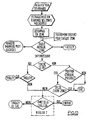
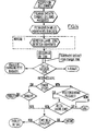
- the diagram of the figure 14 adds to the phases presented on the figure 13 , the detection of a wide area carried out using the IR detection cells placed at the exit of the first door.
- the diagram of the figure 15 adds to the phases shown on the diagram of the figure 13 those implemented at detection level 3.
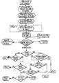
- the diagram of the figure 16 adds to the phases shown on the diagram of the figure 13 those implemented at detection level 4.
- the diagram of the figure 17 adds to the phases shown on the diagram of the figure 13 those implemented at detection level 5.
- the active infra-red detectors D1 form an infra-red beam curtain which is crossed by one or more people and possibly an object.
- the UC control unit establishes profiles through control logic.
- This filtering corresponds on the one hand to a recovery of the data and on the other hand to a cleaning of parasitic information.
- the profile is divided into zones that will be treated separately. To do this, we detect the transitions (growth / decay). This phase is illustrated by the figure 18 .
- the maxima and minima of the profiles are also determined (see figure 19 ).
- the maxima correspond to possible people and the minima make it possible to isolate groups.
- For each zone is determined the number of continuous cells maximum. This makes it possible to define the dimension of the object belonging to this zone.
- an object less than 50 cm for example can not be a man, even a newborn.
- an object of more than 1 m 50 for example of height will be detected as a man (so if someone enters the airlock with a big double bass, it is likely that a fraud will be declared. note that if the parameter is adjusted to 1 m 70 this case will be solved but the risk of non detection will be slightly increased).
- This function has the simple purpose of splitting two cases to treat separately because having different characteristics.
- This part of the algorithm makes it possible to check if it is about a child or a trolley, because a trolley is inclined and has a rectilinear side, which does not have a child.
- This function is used to determine the spacing between two zones.
- the object does not touch the ground, it can only be a bag held at arm's length, or a schoolbag on a trolley, ...
- the other functions belong to the other detection levels whose operating principle was previously described.
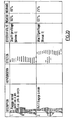
- the figures 20 and 21 illustrate several examples successively showing a person (example 1 figure 20 ) normally passing through the access door, a person carrying a carry-on baggage (Example 2 figure 20 ), a person carrying a trolley and carrying a schoolbag (examples 3 and 4 - figure 21 ).
- the figures 20 and 21 show for each example, the profile obtained, the levels of detection, the result (success rate) and the rate of occurrence.
- the level of detection 1 is sufficient to identify a single person and a person carrying a luggage.
Landscapes
- Geophysics And Detection Of Objects (AREA)
- Power-Operated Mechanisms For Wings (AREA)
- Elevator Door Apparatuses (AREA)
- Automobile Manufacture Line, Endless Track Vehicle, Trailer (AREA)
- Burglar Alarm Systems (AREA)
Claims (38)
- Verfahren zum Erfassen eines Durchgangs durch eine zugeordnete Zugangstür, beispielsweise eine Immigrationsschleuse, eine Fahrzeugeinstiegstür oder einen Eingang in ein gesichertes Gebäude, um insbesondere die Einzigkeit des Durchgangs einer Person zu gewährleisten, wobei das Profil der Person mittels einer vertikalen Reihe von Infrarot-Sendezellen (D1) bestimmt wird, die am Eingang der Tür gegenüber von Empfangszellen angeordnet sind, die mit einer Steuereinheit (UC) verbunden sind, die die Abtastung und den Aussendetakt der Signale steuert, wobei in Abhängigkeit von diesem Profil die Zugangstür geöffnet oder geschlossen gehalten wird, dadurch gekennzeichnet, dass:- bestimmte Zonen des Profils gefiltert werden, um sie abzudecken oder um Störzonen zu beseitigen,- das Profil in Zonen zerlegt wird, die getrennt verarbeitet werden, und- jede Zone in Abhängigkeit von ihrer Abmessung charakterisiert wird, um zu bestimmen, ob die Zone einem Menschen, einem Kind oder einem Objekt entspricht.
- Verfahren nach Anspruch 1, dadurch gekennzeichnet, dass jede Zone, die den Boden berührt, charakterisiert wird, um durch die Form der Zone ein Kind von einem Wagen und ein Kind von einem Schulranzen oder einem Rucksack zu unterscheiden.
- Verfahren nach einem der Ansprüche 1 oder 2, dadurch gekennzeichnet, dass jede Zone, die den Boden nicht berührt, charakterisiert wird, um ein getragenes Kind von einem Gepäckstück zu unterscheiden.
- Verfahren nach einem der vorhergehenden Ansprüche, dadurch gekennzeichnet, dass eine zusätzliche Filterung ausgeführt wird, um die Rückwärtsbewegungen der Person zu beseitigen.
- Verfahren nach einem der vorhergehenden Ansprüche, dadurch gekennzeichnet, dass die Profile auf ihre wahre Größe reduziert werden.
- Verfahren nach einem der vorhergehenden Ansprüche, dadurch gekennzeichnet, dass nach der Zerlegung des Profils in Zonen die Größe und das Volumen jeder Zone bestimmt werden.
- Verfahren nach einem der vorhergehenden Ansprüche, dadurch gekennzeichnet, dass nach einer Identifizierung einer den Boden berührenden Zone in Abhängigkeit vom Volumen der Zone ein Wagen oder eine Tasche identifiziert werden.
- Verfahren nach einem der vorhergehenden Ansprüche, dadurch gekennzeichnet, dass nach einer Identifizierung einer den Boden nicht berührenden Zone in Abhängigkeit vom Volumen der Zone ein Kind oder eine Tasche identifiziert werden.
- Verfahren nach einem der vorhergehenden Ansprüche, dadurch gekennzeichnet, dass nach der Filterung und vor der Zerlegung in Zonen der gleichzeitige Durchgang mehrerer Personen erfasst wird.
- Verfahren nach einem der vorhergehenden Ansprüche, dadurch gekennzeichnet, dass anhand des erhaltenen Profils insbesondere erfasst wird:- eine Person, die von einem Kind begleitet wird,- zwei Personen, die sehr nahe aufeinander folgen,- eine vorwärts, dann rückwärts und dann erneut vorwärts gehende Person,- eine springende Person,- ein Kind, das einem großen Wagen folgt,- eine Person, die einen Rucksack trägt,- eine Person, die ein Kind auf dem Rücken trägt.
- Verfahren nach einem der vorhergehenden Ansprüche, dadurch gekennzeichnet, dass mittels eines Geschwindigkeitsdetektors (D3) die Durchgangsgeschwindigkeit der Person bestimmt wird und dass das durch die erste Erfassungsstufe erzeugte Profil modifiziert wird, um ein von der Durchgangsgeschwindigkeit unabhängiges Profil zu erhalten.
- Verfahren nach Anspruch 11, dadurch gekennzeichnet, dass die Durchgangsgeschwindigkeit mittels eines Doppler-Radars (D3) bestimmt wird.
- Verfahren nach Anspruch 11, dadurch gekennzeichnet, dass die Durchgangsgeschwindigkeit mittels eines Abstandssensors bestimmt wird.
- Verfahren nach Anspruch 11, dadurch gekennzeichnet, dass die Durchgangsgeschwindigkeit durch aufeinander folgendes Durchqueren von wenigstens zwei Infrarotbarrieren bestimmt wird.
- Verfahren nach einem der vorhergehenden Ansprüche, dadurch gekennzeichnet, dass mittels einer zweiten Erfassungsstufe, die aus wenigstens einer Passiv-Infrarotzelle (D2) gebildet ist, das Vorhandensein eines kalten Körpers erfasst wird.
- Verfahren nach Anspruch 15, dadurch gekennzeichnet, dass die zweite Erfassungsstufe einer dritten Erfassungsstufe vorhergeht, die durch den Detektor (D3) für die Bewegungsrichtung gebildet ist.
- Verfahren nach Anspruch 16, dadurch gekennzeichnet, dass die dritte Erfassungsstufe einer vierten Erfassungsstufe vorhergeht, die durch den Geschwindigkeitsdetektor (D3) gebildet ist.
- Verfahren nach Anspruch 17, dadurch gekennzeichnet, dass mittels einer fünften Erfassungsstufe(D4) der gleichzeitige Durchgang von zwei Personen erfasst wird.
- Verfahren nach Anspruch 18, dadurch gekennzeichnet, dass die Erfassung mittels Ultraschalldetektoren (D4), die quer zum Durchgang angeordnet sind, erfolgt.
- Verfahren nach Anspruch 18, dadurch gekennzeichnet, dass die Erfassung mittels eines Lasers erfolgt, der mit einem Drehspiegel zusammenwirkt, um das Profil in einer Ebene senkrecht zu dem eigentlichen Profil zu bestimmen.
- Verfahren nach Anspruch 18, dadurch gekennzeichnet, dass die Erfassung mittels einer Erkennung eines Bildes erfolgt, das gegenüber dem Durchgang aufgenommen wird, um das Profil in einer Ebene, die zu dem eigentlichen Profil senkrecht ist, zu bestimmen.
- Verfahren nach Anspruch 18, dadurch gekennzeichnet, dass die Erfassung mittels einer kapazitiven Messung (DMI) erfolgt.
- Verfahren nach Anspruch 18, dadurch gekennzeichnet, dass die Erfassung mittels Abstandssensoren erfolgt, um die Position der Füße zu erfassen, um zu bestimmen:a) ob eine Person sehr weit ausgereizte Beine hat,b) ob eine Person einen Wagen neben sich hat,c) ob zwei Personen gleichzeitig hindurchgehen.
- Verfahren nach Anspruch 23, dadurch gekennzeichnet, dass für die Unterscheidung der Fälle b) und c) Wärmesensoren verwendet werden.
- Verfahren nach Anspruch 18, dadurch gekennzeichnet, dass die Erfassung durch zwei sich kreuzende Reihen von Detektoren der Stufe 1 ausgeführt wird.
- Verfahren nach Anspruch 18, dadurch gekennzeichnet, dass die Erfassung durch ein kapazitives Messsystem ausgeführt wird, das für die dielektrische Charakteristiken des menschlichen Körpers empfindlich ist.
- Verfahren nach einem der Ansprüche 11 bis 26, dadurch gekennzeichnet, dass mittels des Geschwindigkeitsdetektors (D3) eine Person erfasst wird, die hin und zurück geht.
- Einrichtung zur Erfassung eines Durchgangs durch eine zugeordnete Zugangstür, beispielsweise beim Einsteigen oder beim Eintreten in ein gesichertes Gebäude, um insbesondere die Einzigkeit des Durchgangs einer Person zu gewährleisten, wobei diese Einrichtung aufweist:- eine erste Erfassungsstufe, die gebildet ist aus einer vertikalen Reihe aus Aktiv-InfrarotSendezellen (D1), die gegenüber einer vertikalen Reihe aus Empfangszellen angeordnet sind, um das Profil einer eintretenden Person zu bestimmen, wobei diese Zellen mit einer Zentraleinheit (UC) verbunden sind, die steuert: einerseits die Abtastung und den Aussendetakt der Signale, und andererseits Mittel zum Steuern des Öffnens oder des Aufrechterhaltens des geschlossenen Zustands der Zugangstür,dadurch gekennzeichnet, dass die Einrichtung aufweist: Mittel, um bestimmte Zonen des Profils zu filtern, um sie abzudecken oder um Störzonen zu beseitigen, Mittel, um das Profil in Zonen zu zerlegen, Mittel, um die zerlegten Zonen getrennt zu verarbeiten, und Mittel, um jede Zone als Funktion ihrer Abmessung zu charakterisieren, um zu bestimmen, ob die Zone einem Menschen, einem Kind oder einem Objekt entspricht.
- Einrichtung nach Anspruch 28, dadurch gekennzeichnet, dass sie eine zweite Erfassungsstufe enthält, die aus einer Passiv-Infrarotzelle (D2) gebildet ist, um das Vorhandensein eines kalten Körpers zu erfassen.
- Einrichtung nach einem der Ansprüche 28 oder 29, dadurch gekennzeichnet, dass sie enthält:- einen Geschwindigkeitsdetektor (D3), um die Durchgangsgeschwindigkeit der Person zu bestimmen,- Mittel, um das durch die erste Erfassungsstufe bestimmte Profil abzuwandeln, um ein von der Durchgangsgeschwindigkeit unabhängiges Profil zu erhalten, und- Mittel, um das erhaltene Profil mit einer in einem Speicher enthaltenen Architektur von Profilen zu vergleichen.
- Einrichtung nach Anspruch 30, dadurch gekennzeichnet, dass die Mittel zum Bestimmen der Durchgangsgeschwindigkeit ein Doppler-Radar (D3) enthalten.
- Einrichtung nach Anspruch 30, dadurch gekennzeichnet, dass die zweite Erfassungsstufe der dritten Erfassungsstufe vorhergeht, die durch den Geschwindigkeitsdetektor (D3) gebildet ist.
- Einrichtung nach einem der Ansprüche 28 bis 32, dadurch gekennzeichnet, dass sie eine Erfassungsstufe enthält, um den gleichzeitigen Durchgang von zwei Personen zu erfassen, die Ultraschalldetektoren (D4) enthält, die quer zum Durchgang angeordnet sind.
- Einrichtung nach einem der Ansprüche 28 bis 33, dadurch gekennzeichnet, dass sie eine Zentraleinheit (UC) enthält, die mit den verschiedenen Erfassungsstufen und mit einem Speicher (M) kommuniziert, der eine Architektur von Profilen enthält, wobei diese Steuereinheit (UC) dazu ausgelegt ist, die durch die Detektoren (D1, D2, D3, D4) bestimmten Profile mit den im Speicher enthaltenen Profilen zu vergleichen und als Funktion der Ergebnisse dieses Vergleichs das Öffnen der Zugangstür oder das Halten der Zugangstür im geschlossenen Zustand und eventuell das Auslösen eines Alarms zu steuern.
- Einrichtung nach einem der Ansprüche 32 bis 34, dadurch gekennzeichnet, dass das Radar (D3) der dritten Erfassungsstufe in einem bestimmten Abstand von dem Eingang (1) der Zugangstür angeordnet ist und orientiert ist, um sein Strahlenbündel zu diesem Eingang (1) zu schicken.
- Einrichtung nach einem der Ansprüche 29 bis 35, dadurch gekennzeichnet, dass die Passiv-Infrarotzellen (D2) der zweiten Erfassungsstufe wenigstens zwei Zellen enthalten, die am Eingang (1) der Tür übereinander angeordnet und orientiert sind, um ihr Strahlenbündel quer zu dem Durchgang zu schicken.
- Einrichtung nach einem der Ansprüche 33 bis 36, dadurch gekennzeichnet, dass die Detektoren der Erfassungsstufe für den gleichzeitigen Durchgang mehrerer Personen wenigstens drei Ultraschalldetektoren (D4) enthalten, die im oberen Teil des Eingangs (1) der Zugangstür angeordnet sind und orientiert sind, um ihre Strahlenbündel nach unten auszusenden.
- Einrichtung nach einem der Ansprüche 28 bis 37, wobei die Zugangstür bidirektional ist, dadurch gekennzeichnet, dass der Eingang (1) und der Ausgang (2) der Tür jeweils eine Gesamtheit von Detektoren (D1, D2, D3, D4), die gleiche Funktionen haben, enthalten.
Applications Claiming Priority (2)
| Application Number | Priority Date | Filing Date | Title |
|---|---|---|---|
| FR0402729A FR2867864B1 (fr) | 2004-03-17 | 2004-03-17 | Procede et installation de detection de passage associe a une porte d'acces |
| PCT/FR2004/001786 WO2005101062A1 (fr) | 2004-03-17 | 2004-07-08 | Procede et installation de detection de passage associe a une porte d’acces |
Publications (2)
| Publication Number | Publication Date |
|---|---|
| EP1730554A1 EP1730554A1 (de) | 2006-12-13 |
| EP1730554B1 true EP1730554B1 (de) | 2009-09-16 |
Family
ID=34896580
Family Applications (1)
| Application Number | Title | Priority Date | Filing Date |
|---|---|---|---|
| EP04767618A Expired - Lifetime EP1730554B1 (de) | 2004-03-17 | 2004-07-08 | Verfahren und einrichtung zur erkennung eines mit einer zugangstür assoziierten durchgangs |
Country Status (9)
| Country | Link |
|---|---|
| US (1) | US20070194917A1 (de) |
| EP (1) | EP1730554B1 (de) |
| AT (1) | ATE443274T1 (de) |
| CA (1) | CA2559730A1 (de) |
| DE (1) | DE602004023235D1 (de) |
| DK (1) | DK1730554T3 (de) |
| ES (1) | ES2334235T3 (de) |
| FR (1) | FR2867864B1 (de) |
| WO (1) | WO2005101062A1 (de) |
Families Citing this family (12)
| Publication number | Priority date | Publication date | Assignee | Title |
|---|---|---|---|---|
| WO2009086928A1 (fr) * | 2008-01-08 | 2009-07-16 | Automatic Systems | Procede, systeme et installation de detection pour garantir l'unicite de passage d'un objet |
| US8654197B2 (en) * | 2009-03-04 | 2014-02-18 | Raytheon Company | System and method for occupancy detection |
| ES2544504B1 (es) * | 2014-02-28 | 2016-08-31 | Oscar RODRIGO SIMARRO | Detector por altura de áreas de riesgos infantiles |
| EP3309756B1 (de) * | 2016-10-14 | 2020-12-30 | Fichet Technologies | Einzelpassage-kontrollverfahren und -kontrollsystem, das eine umsetzung dieses verfahrens ermöglicht, sowie vorrichtung für tür oder korridor, die mit einem solchen system ausgestattet ist |
| USD837844S1 (en) * | 2017-04-13 | 2019-01-08 | Peter Simpson | Air lock access door |
| EP3503045B1 (de) * | 2017-12-22 | 2024-08-07 | Gunnebo Entrance Control Limited | Drehkreuz mit durschlupfdetektion und alarm |
| CN111287602B (zh) * | 2020-02-11 | 2025-03-04 | 北京小米移动软件有限公司 | 开关门装置和控制开关门的方法 |
| US12400500B2 (en) | 2020-06-03 | 2025-08-26 | Dormakaba Schweiz Ag | Access gate |
| CN112965140B (zh) * | 2021-02-07 | 2023-02-24 | 杭州睿影科技有限公司 | 一种通道检测设备、以及主控板 |
| CN113009588B (zh) * | 2021-03-01 | 2023-05-02 | 杭州睿影科技有限公司 | 基于毫米波成像的人体安检设备 |
| WO2023039485A1 (en) * | 2021-09-08 | 2023-03-16 | Boon Edam, Inc. | Separation systems, piggybacking detection devices, and related computer program products for controlling access to a restricted area and related methods |
| CN118053231B (zh) * | 2024-04-15 | 2024-07-02 | 盛视科技股份有限公司 | 人行通道开门感应方法及通道闸机设备 |
Family Cites Families (29)
| Publication number | Priority date | Publication date | Assignee | Title |
|---|---|---|---|---|
| DE2833074A1 (de) * | 1977-07-28 | 1979-02-08 | Petrovskij | Doppler-effekt-funkmessgeschwindigkeitsmesser fuer sich bewegende objekte |
| US4317117A (en) * | 1979-07-20 | 1982-02-23 | Chasek Norman E | Cross correlated doppler radar/infra red velocity and presence sensor |
| DE3673699D1 (de) * | 1985-05-23 | 1990-10-04 | Contraves Ag | Rundsuchsystem zur raum-/luftraumueberwachung. |
| US5001558A (en) * | 1985-06-11 | 1991-03-19 | General Motors Corporation | Night vision system with color video camera |
| WO1988000745A1 (en) * | 1986-07-24 | 1988-01-28 | Keith Jeffrey Gate | Detection system |
| US5201906A (en) * | 1989-10-11 | 1993-04-13 | Milan Schwarz | Anti-piggybacking: sensor system for security door to detect two individuals in one compartment |
| IL100173A (en) * | 1991-11-27 | 1994-05-30 | Visonic Ltd | Burglary detection device |
| ZA929406B (en) * | 1992-03-04 | 1993-09-27 | Csir | Monitoring system |
| DE4400190C2 (de) * | 1994-01-05 | 1996-07-11 | Bernd Poley | Sicherheitsschleuse und Verfahren zum Aufspüren von durch Personen in eine Sicherheitsschleuse eingebrachten Gegenständen |
| DE19635934A1 (de) * | 1996-09-05 | 1998-03-12 | Guenter Prof Dr Ing Kompa | Laserradar-Geschwindigkeitsmessung |
| US6760061B1 (en) * | 1997-04-14 | 2004-07-06 | Nestor Traffic Systems, Inc. | Traffic sensor |
| GB2326710A (en) * | 1997-06-26 | 1998-12-30 | Memco Ltd | Door obstruction detector |
| US7389914B1 (en) * | 1998-10-09 | 2008-06-24 | Diebold, Incorporated | Method of capturing and communicating correlated data of check transaction at card reading automated banking machine |
| WO2000023958A1 (en) * | 1998-10-20 | 2000-04-27 | Georal International Ltd. | Security entrance system |
| US6940998B2 (en) * | 2000-02-04 | 2005-09-06 | Cernium, Inc. | System for automated screening of security cameras |
| US6167991B1 (en) * | 2000-02-28 | 2001-01-02 | Otis Elevator Company | Method and apparatus for detecting position of an elevator door |
| US6825752B2 (en) * | 2000-06-13 | 2004-11-30 | Siemens Vdo Automotive Corporation | Effortless entry system and method |
| JP2002057564A (ja) * | 2000-08-11 | 2002-02-22 | Aisin Seiki Co Ltd | 人体検出器 |
| US6720874B2 (en) * | 2000-09-29 | 2004-04-13 | Ids Systems, Inc. | Portal intrusion detection apparatus and method |
| US6633232B2 (en) * | 2001-05-14 | 2003-10-14 | Koninklijke Philips Electronics N.V. | Method and apparatus for routing persons through one or more destinations based on a least-cost criterion |
| US20030018522A1 (en) * | 2001-07-20 | 2003-01-23 | Psc Scanning, Inc. | Biometric system and method for identifying a customer upon entering a retail establishment |
| US7305108B2 (en) * | 2001-11-08 | 2007-12-04 | Pelco | Security identification system |
| US7688349B2 (en) * | 2001-12-07 | 2010-03-30 | International Business Machines Corporation | Method of detecting and tracking groups of people |
| US20030117280A1 (en) * | 2001-12-20 | 2003-06-26 | Visionary Enterprises, Inc. | Security communication and remote monitoring/response system |
| US6741177B2 (en) * | 2002-03-28 | 2004-05-25 | Verifeye Inc. | Method and apparatus for detecting items on the bottom tray of a cart |
| US7221775B2 (en) * | 2002-11-12 | 2007-05-22 | Intellivid Corporation | Method and apparatus for computerized image background analysis |
| US7394916B2 (en) * | 2003-02-10 | 2008-07-01 | Activeye, Inc. | Linking tracked objects that undergo temporary occlusion |
| US7081818B2 (en) * | 2003-05-19 | 2006-07-25 | Checkpoint Systems, Inc. | Article identification and tracking using electronic shadows created by RFID tags |
| US6911907B2 (en) * | 2003-09-26 | 2005-06-28 | General Electric Company | System and method of providing security for a site |
-
2004
- 2004-03-17 FR FR0402729A patent/FR2867864B1/fr not_active Expired - Fee Related
- 2004-07-08 ES ES04767618T patent/ES2334235T3/es not_active Expired - Lifetime
- 2004-07-08 DK DK04767618T patent/DK1730554T3/da active
- 2004-07-08 AT AT04767618T patent/ATE443274T1/de active
- 2004-07-08 WO PCT/FR2004/001786 patent/WO2005101062A1/fr not_active Ceased
- 2004-07-08 DE DE602004023235T patent/DE602004023235D1/de not_active Expired - Lifetime
- 2004-07-08 CA CA002559730A patent/CA2559730A1/fr not_active Abandoned
- 2004-07-08 EP EP04767618A patent/EP1730554B1/de not_active Expired - Lifetime
- 2004-07-08 US US10/592,933 patent/US20070194917A1/en not_active Abandoned
Also Published As
| Publication number | Publication date |
|---|---|
| ES2334235T3 (es) | 2010-03-08 |
| FR2867864B1 (fr) | 2007-03-02 |
| DK1730554T3 (da) | 2010-01-11 |
| WO2005101062A1 (fr) | 2005-10-27 |
| ATE443274T1 (de) | 2009-10-15 |
| DE602004023235D1 (de) | 2009-10-29 |
| FR2867864A1 (fr) | 2005-09-23 |
| US20070194917A1 (en) | 2007-08-23 |
| EP1730554A1 (de) | 2006-12-13 |
| CA2559730A1 (fr) | 2005-10-27 |
Similar Documents
| Publication | Publication Date | Title |
|---|---|---|
| EP1730554A1 (de) | Verfahren und einrichtung zur erkennung eines mit einer zugangstür assoziierten durchgangs | |
| WO2021180060A1 (zh) | 一种通道闸机的控制方法、装置及系统 | |
| EP1960973B1 (de) | Verfahren zum sichern eines physischen zugangs und das verfahren implementierende zugangseinrichtung | |
| US10838105B2 (en) | Optical system for monitoring the movement of people through a passageway | |
| JP6881898B2 (ja) | ゲート装置 | |
| US20200134342A1 (en) | Spoof detection using multiple image acquisition devices | |
| FR2995432A1 (fr) | Procede d'ouverture/fermeture d'ouvrant en acces main libre securise par detection de mouvement de membre inferieur d'utilisateur | |
| US12069380B2 (en) | Solar blind imaging | |
| FR3086782A1 (fr) | Dispositif et procede de comptage de personnes | |
| KR20230146540A (ko) | 얼굴 잠금 해제를 위한 광학 피부 검출 | |
| EP3960686A1 (de) | Anlage für zugangskontrolle | |
| WO2004063994A1 (fr) | Système de contrôle d'accès | |
| FR3015730A1 (fr) | Procede de detection de personnes et ou d'objets dans un espace | |
| WO2009086928A1 (fr) | Procede, systeme et installation de detection pour garantir l'unicite de passage d'un objet | |
| CN117377992A (zh) | 一种门禁设备和用于控制门禁设备的方法 | |
| CN205845117U (zh) | 具有光矩阵的防跟随通道闸 | |
| FR3015731A1 (fr) | Procede d'estimation du nombre de personnes et ou d'obets dans un espace | |
| FR3015732A1 (fr) | Procede de detection de personnes et ou d'objets dans un espace | |
| FR3117234A1 (fr) | Méthode de comptage automatique des entrées et sorties de personnes empruntant un lieu de passage identifié | |
| EP3067709A1 (de) | Verfahren und vorrichtung zum nachverfolgen von personen in einem ort, die mit verschiedenen verteilten erfassungsmitteln ausgestattet ist | |
| EP2985635B1 (de) | Schranke zur zugangskontrolle | |
| EP2329474B1 (de) | Verfahren und system für szenenbeobachtung | |
| FR2872326A1 (fr) | Procede de detection d'evenements par videosurveillance | |
| Baron Sam et al. | Doorbell System in Home Using IoT | |
| CZ306898B6 (cs) | Způsob detekce pokusů o neoprávněný průchod do chráněných prostor |
Legal Events
| Date | Code | Title | Description |
|---|---|---|---|
| PUAI | Public reference made under article 153(3) epc to a published international application that has entered the european phase |
Free format text: ORIGINAL CODE: 0009012 |
|
| 17P | Request for examination filed |
Effective date: 20061016 |
|
| AK | Designated contracting states |
Kind code of ref document: A1 Designated state(s): AT BE BG CH CY CZ DE DK EE ES FI FR GB GR HU IE IT LI LU MC NL PL PT RO SE SI SK TR |
|
| 17Q | First examination report despatched |
Effective date: 20070306 |
|
| DAX | Request for extension of the european patent (deleted) | ||
| GRAP | Despatch of communication of intention to grant a patent |
Free format text: ORIGINAL CODE: EPIDOSNIGR1 |
|
| GRAS | Grant fee paid |
Free format text: ORIGINAL CODE: EPIDOSNIGR3 |
|
| GRAA | (expected) grant |
Free format text: ORIGINAL CODE: 0009210 |
|
| AK | Designated contracting states |
Kind code of ref document: B1 Designated state(s): AT BE BG CH CY CZ DE DK EE ES FI FR GB GR HU IE IT LI LU MC NL PL PT RO SE SI SK TR |
|
| REG | Reference to a national code |
Ref country code: GB Ref legal event code: FG4D Free format text: NOT ENGLISH |
|
| REG | Reference to a national code |
Ref country code: CH Ref legal event code: EP |
|
| REG | Reference to a national code |
Ref country code: IE Ref legal event code: FG4D |
|
| REF | Corresponds to: |
Ref document number: 602004023235 Country of ref document: DE Date of ref document: 20091029 Kind code of ref document: P |
|
| REG | Reference to a national code |
Ref country code: CH Ref legal event code: NV Representative=s name: DR. JOACHIM LAUER PATENTANWALT |
|
| REG | Reference to a national code |
Ref country code: SE Ref legal event code: TRGR |
|
| REG | Reference to a national code |
Ref country code: DK Ref legal event code: T3 |
|
| PG25 | Lapsed in a contracting state [announced via postgrant information from national office to epo] |
Ref country code: FI Free format text: LAPSE BECAUSE OF FAILURE TO SUBMIT A TRANSLATION OF THE DESCRIPTION OR TO PAY THE FEE WITHIN THE PRESCRIBED TIME-LIMIT Effective date: 20090916 |
|
| PG25 | Lapsed in a contracting state [announced via postgrant information from national office to epo] |
Ref country code: PL Free format text: LAPSE BECAUSE OF FAILURE TO SUBMIT A TRANSLATION OF THE DESCRIPTION OR TO PAY THE FEE WITHIN THE PRESCRIBED TIME-LIMIT Effective date: 20090916 Ref country code: SI Free format text: LAPSE BECAUSE OF FAILURE TO SUBMIT A TRANSLATION OF THE DESCRIPTION OR TO PAY THE FEE WITHIN THE PRESCRIBED TIME-LIMIT Effective date: 20090916 |
|
| REG | Reference to a national code |
Ref country code: ES Ref legal event code: FG2A Ref document number: 2334235 Country of ref document: ES Kind code of ref document: T3 |
|
| PG25 | Lapsed in a contracting state [announced via postgrant information from national office to epo] |
Ref country code: CY Free format text: LAPSE BECAUSE OF FAILURE TO SUBMIT A TRANSLATION OF THE DESCRIPTION OR TO PAY THE FEE WITHIN THE PRESCRIBED TIME-LIMIT Effective date: 20090916 |
|
| REG | Reference to a national code |
Ref country code: IE Ref legal event code: FD4D |
|
| PG25 | Lapsed in a contracting state [announced via postgrant information from national office to epo] |
Ref country code: PT Free format text: LAPSE BECAUSE OF FAILURE TO SUBMIT A TRANSLATION OF THE DESCRIPTION OR TO PAY THE FEE WITHIN THE PRESCRIBED TIME-LIMIT Effective date: 20100118 Ref country code: CZ Free format text: LAPSE BECAUSE OF FAILURE TO SUBMIT A TRANSLATION OF THE DESCRIPTION OR TO PAY THE FEE WITHIN THE PRESCRIBED TIME-LIMIT Effective date: 20090916 Ref country code: EE Free format text: LAPSE BECAUSE OF FAILURE TO SUBMIT A TRANSLATION OF THE DESCRIPTION OR TO PAY THE FEE WITHIN THE PRESCRIBED TIME-LIMIT Effective date: 20090916 Ref country code: IE Free format text: LAPSE BECAUSE OF FAILURE TO SUBMIT A TRANSLATION OF THE DESCRIPTION OR TO PAY THE FEE WITHIN THE PRESCRIBED TIME-LIMIT Effective date: 20090916 Ref country code: RO Free format text: LAPSE BECAUSE OF FAILURE TO SUBMIT A TRANSLATION OF THE DESCRIPTION OR TO PAY THE FEE WITHIN THE PRESCRIBED TIME-LIMIT Effective date: 20090916 |
|
| PG25 | Lapsed in a contracting state [announced via postgrant information from national office to epo] |
Ref country code: SK Free format text: LAPSE BECAUSE OF FAILURE TO SUBMIT A TRANSLATION OF THE DESCRIPTION OR TO PAY THE FEE WITHIN THE PRESCRIBED TIME-LIMIT Effective date: 20090916 |
|
| PLBE | No opposition filed within time limit |
Free format text: ORIGINAL CODE: 0009261 |
|
| STAA | Information on the status of an ep patent application or granted ep patent |
Free format text: STATUS: NO OPPOSITION FILED WITHIN TIME LIMIT |
|
| 26N | No opposition filed |
Effective date: 20100617 |
|
| PG25 | Lapsed in a contracting state [announced via postgrant information from national office to epo] |
Ref country code: GR Free format text: LAPSE BECAUSE OF FAILURE TO SUBMIT A TRANSLATION OF THE DESCRIPTION OR TO PAY THE FEE WITHIN THE PRESCRIBED TIME-LIMIT Effective date: 20091217 |
|
| PG25 | Lapsed in a contracting state [announced via postgrant information from national office to epo] |
Ref country code: MC Free format text: LAPSE BECAUSE OF NON-PAYMENT OF DUE FEES Effective date: 20100731 |
|
| PG25 | Lapsed in a contracting state [announced via postgrant information from national office to epo] |
Ref country code: HU Free format text: LAPSE BECAUSE OF FAILURE TO SUBMIT A TRANSLATION OF THE DESCRIPTION OR TO PAY THE FEE WITHIN THE PRESCRIBED TIME-LIMIT Effective date: 20100317 Ref country code: LU Free format text: LAPSE BECAUSE OF NON-PAYMENT OF DUE FEES Effective date: 20100708 Ref country code: BG Free format text: LAPSE BECAUSE OF FAILURE TO SUBMIT A TRANSLATION OF THE DESCRIPTION OR TO PAY THE FEE WITHIN THE PRESCRIBED TIME-LIMIT Effective date: 20090916 |
|
| REG | Reference to a national code |
Ref country code: CH Ref legal event code: PCAR Free format text: DR. JOACHIM LAUER C/O RENTSCH PARTNER AG;FRAUMUENSTERSTRASSE 9 POSTFACH 2441;8022 ZUERICH (CH) |
|
| PG25 | Lapsed in a contracting state [announced via postgrant information from national office to epo] |
Ref country code: TR Free format text: LAPSE BECAUSE OF FAILURE TO SUBMIT A TRANSLATION OF THE DESCRIPTION OR TO PAY THE FEE WITHIN THE PRESCRIBED TIME-LIMIT Effective date: 20090916 |
|
| PGFP | Annual fee paid to national office [announced via postgrant information from national office to epo] |
Ref country code: DK Payment date: 20140721 Year of fee payment: 11 Ref country code: CH Payment date: 20140721 Year of fee payment: 11 |
|
| PGFP | Annual fee paid to national office [announced via postgrant information from national office to epo] |
Ref country code: SE Payment date: 20140721 Year of fee payment: 11 |
|
| PGFP | Annual fee paid to national office [announced via postgrant information from national office to epo] |
Ref country code: IT Payment date: 20140730 Year of fee payment: 11 |
|
| PGFP | Annual fee paid to national office [announced via postgrant information from national office to epo] |
Ref country code: NL Payment date: 20150721 Year of fee payment: 12 |
|
| PGFP | Annual fee paid to national office [announced via postgrant information from national office to epo] |
Ref country code: BE Payment date: 20150721 Year of fee payment: 12 Ref country code: AT Payment date: 20150722 Year of fee payment: 12 |
|
| REG | Reference to a national code |
Ref country code: DK Ref legal event code: EBP Effective date: 20150731 |
|
| REG | Reference to a national code |
Ref country code: CH Ref legal event code: PL |
|
| REG | Reference to a national code |
Ref country code: SE Ref legal event code: EUG |
|
| PG25 | Lapsed in a contracting state [announced via postgrant information from national office to epo] |
Ref country code: IT Free format text: LAPSE BECAUSE OF NON-PAYMENT OF DUE FEES Effective date: 20150708 Ref country code: CH Free format text: LAPSE BECAUSE OF NON-PAYMENT OF DUE FEES Effective date: 20150731 Ref country code: LI Free format text: LAPSE BECAUSE OF NON-PAYMENT OF DUE FEES Effective date: 20150731 |
|
| PG25 | Lapsed in a contracting state [announced via postgrant information from national office to epo] |
Ref country code: SE Free format text: LAPSE BECAUSE OF NON-PAYMENT OF DUE FEES Effective date: 20150709 |
|
| REG | Reference to a national code |
Ref country code: FR Ref legal event code: PLFP Year of fee payment: 13 |
|
| PG25 | Lapsed in a contracting state [announced via postgrant information from national office to epo] |
Ref country code: DK Free format text: LAPSE BECAUSE OF NON-PAYMENT OF DUE FEES Effective date: 20150731 |
|
| PG25 | Lapsed in a contracting state [announced via postgrant information from national office to epo] |
Ref country code: BE Free format text: LAPSE BECAUSE OF NON-PAYMENT OF DUE FEES Effective date: 20160731 |
|
| PGFP | Annual fee paid to national office [announced via postgrant information from national office to epo] |
Ref country code: ES Payment date: 20160715 Year of fee payment: 13 |
|
| REG | Reference to a national code |
Ref country code: NL Ref legal event code: MM Effective date: 20160801 |
|
| REG | Reference to a national code |
Ref country code: AT Ref legal event code: MM01 Ref document number: 443274 Country of ref document: AT Kind code of ref document: T Effective date: 20160708 |
|
| PG25 | Lapsed in a contracting state [announced via postgrant information from national office to epo] |
Ref country code: NL Free format text: LAPSE BECAUSE OF NON-PAYMENT OF DUE FEES Effective date: 20160801 |
|
| PG25 | Lapsed in a contracting state [announced via postgrant information from national office to epo] |
Ref country code: AT Free format text: LAPSE BECAUSE OF NON-PAYMENT OF DUE FEES Effective date: 20160708 |
|
| REG | Reference to a national code |
Ref country code: FR Ref legal event code: PLFP Year of fee payment: 14 |
|
| REG | Reference to a national code |
Ref country code: FR Ref legal event code: PLFP Year of fee payment: 15 |
|
| REG | Reference to a national code |
Ref country code: ES Ref legal event code: FD2A Effective date: 20181107 |
|
| PG25 | Lapsed in a contracting state [announced via postgrant information from national office to epo] |
Ref country code: ES Free format text: LAPSE BECAUSE OF NON-PAYMENT OF DUE FEES Effective date: 20170709 |
|
| PGFP | Annual fee paid to national office [announced via postgrant information from national office to epo] |
Ref country code: DE Payment date: 20190719 Year of fee payment: 16 Ref country code: FR Payment date: 20190730 Year of fee payment: 16 |
|
| PGFP | Annual fee paid to national office [announced via postgrant information from national office to epo] |
Ref country code: GB Payment date: 20190719 Year of fee payment: 16 |
|
| REG | Reference to a national code |
Ref country code: DE Ref legal event code: R119 Ref document number: 602004023235 Country of ref document: DE |
|
| GBPC | Gb: european patent ceased through non-payment of renewal fee |
Effective date: 20200708 |
|
| PG25 | Lapsed in a contracting state [announced via postgrant information from national office to epo] |
Ref country code: GB Free format text: LAPSE BECAUSE OF NON-PAYMENT OF DUE FEES Effective date: 20200708 Ref country code: FR Free format text: LAPSE BECAUSE OF NON-PAYMENT OF DUE FEES Effective date: 20200731 |
|
| PG25 | Lapsed in a contracting state [announced via postgrant information from national office to epo] |
Ref country code: DE Free format text: LAPSE BECAUSE OF NON-PAYMENT OF DUE FEES Effective date: 20210202 |