EP1726407A2 - Perforateur - Google Patents
Perforateur Download PDFInfo
- Publication number
- EP1726407A2 EP1726407A2 EP06010930A EP06010930A EP1726407A2 EP 1726407 A2 EP1726407 A2 EP 1726407A2 EP 06010930 A EP06010930 A EP 06010930A EP 06010930 A EP06010930 A EP 06010930A EP 1726407 A2 EP1726407 A2 EP 1726407A2
- Authority
- EP
- European Patent Office
- Prior art keywords
- striking
- clutch
- hammer drill
- motion
- output bit
- Prior art date
- Legal status (The legal status is an assumption and is not a legal conclusion. Google has not performed a legal analysis and makes no representation as to the accuracy of the status listed.)
- Granted
Links
Images


Classifications
-
- B—PERFORMING OPERATIONS; TRANSPORTING
- B25—HAND TOOLS; PORTABLE POWER-DRIVEN TOOLS; MANIPULATORS
- B25D—PERCUSSIVE TOOLS
- B25D11/00—Portable percussive tools with electromotor or other motor drive
- B25D11/06—Means for driving the impulse member
- B25D11/062—Means for driving the impulse member comprising a wobbling mechanism, swash plate
-
- B—PERFORMING OPERATIONS; TRANSPORTING
- B25—HAND TOOLS; PORTABLE POWER-DRIVEN TOOLS; MANIPULATORS
- B25D—PERCUSSIVE TOOLS
- B25D16/00—Portable percussive machines with superimposed rotation, the rotational movement of the output shaft of a motor being modified to generate axial impacts on the tool bit
- B25D16/003—Clutches specially adapted therefor
-
- B—PERFORMING OPERATIONS; TRANSPORTING
- B25—HAND TOOLS; PORTABLE POWER-DRIVEN TOOLS; MANIPULATORS
- B25D—PERCUSSIVE TOOLS
- B25D16/00—Portable percussive machines with superimposed rotation, the rotational movement of the output shaft of a motor being modified to generate axial impacts on the tool bit
- B25D16/006—Mode changers; Mechanisms connected thereto
-
- B—PERFORMING OPERATIONS; TRANSPORTING
- B25—HAND TOOLS; PORTABLE POWER-DRIVEN TOOLS; MANIPULATORS
- B25D—PERCUSSIVE TOOLS
- B25D17/00—Details of, or accessories for, portable power-driven percussive tools
- B25D17/06—Hammer pistons; Anvils ; Guide-sleeves for pistons
-
- B—PERFORMING OPERATIONS; TRANSPORTING
- B25—HAND TOOLS; PORTABLE POWER-DRIVEN TOOLS; MANIPULATORS
- B25D—PERCUSSIVE TOOLS
- B25D17/00—Details of, or accessories for, portable power-driven percussive tools
- B25D17/08—Means for retaining and guiding the tool bit, e.g. chucks allowing axial oscillation of the tool bit
- B25D17/084—Rotating chucks or sockets
- B25D17/088—Rotating chucks or sockets with radial movable locking elements co-operating with bit shafts specially adapted therefor
-
- B—PERFORMING OPERATIONS; TRANSPORTING
- B25—HAND TOOLS; PORTABLE POWER-DRIVEN TOOLS; MANIPULATORS
- B25D—PERCUSSIVE TOOLS
- B25D2216/00—Details of portable percussive machines with superimposed rotation, the rotational movement of the output shaft of a motor being modified to generate axial impacts on the tool bit
- B25D2216/0007—Details of percussion or rotation modes
- B25D2216/0023—Tools having a percussion-and-rotation mode
-
- B—PERFORMING OPERATIONS; TRANSPORTING
- B25—HAND TOOLS; PORTABLE POWER-DRIVEN TOOLS; MANIPULATORS
- B25D—PERCUSSIVE TOOLS
- B25D2216/00—Details of portable percussive machines with superimposed rotation, the rotational movement of the output shaft of a motor being modified to generate axial impacts on the tool bit
- B25D2216/0007—Details of percussion or rotation modes
- B25D2216/0038—Tools having a rotation-only mode
-
- B—PERFORMING OPERATIONS; TRANSPORTING
- B25—HAND TOOLS; PORTABLE POWER-DRIVEN TOOLS; MANIPULATORS
- B25D—PERCUSSIVE TOOLS
- B25D2217/00—Details of, or accessories for, portable power-driven percussive tools
- B25D2217/003—Details relating to chucks with radially movable locking elements
- B25D2217/0038—Locking members of special shape
- B25D2217/0042—Ball-shaped locking members
-
- B—PERFORMING OPERATIONS; TRANSPORTING
- B25—HAND TOOLS; PORTABLE POWER-DRIVEN TOOLS; MANIPULATORS
- B25D—PERCUSSIVE TOOLS
- B25D2250/00—General details of portable percussive tools; Components used in portable percussive tools
- B25D2250/165—Overload clutches, torque limiters
-
- B—PERFORMING OPERATIONS; TRANSPORTING
- B25—HAND TOOLS; PORTABLE POWER-DRIVEN TOOLS; MANIPULATORS
- B25D—PERCUSSIVE TOOLS
- B25D2250/00—General details of portable percussive tools; Components used in portable percussive tools
- B25D2250/191—Ram catchers for stopping the ram when entering idling mode
Definitions
- the present invention relates to a hammer drill adapted to apply an axial striking force against a rotatingly driven output bit through the use of reciprocating movement of a striker caused by means of a motion conversion member.
- Hammer drills are employed to do a task of, e.g., drilling a concrete structures. There arises such an instance that a screw is tightened to an anchor embedded into a hole formed by the drilling work.
- typical hammer drills are always accompanied by striking motion and therefore cannot be used in tightening the screw, which requires the additional use of an electric driver.
- This type of hammer drill has no ability to tighten the screw with a suitable torque but tends to, not infrequently, tighten the screw too heavily.
- Japanese Patent Laid-open Publication Nos. 2000-233306 and H7-1355 disclose a vibratory drill and an impact drill wherein a vibratory load or an impact load can be released and a tightening torque can be controlled using a tightening-torque adjusting clutch.
- no tightening-torque adjusting clutch has heretofore been employed in the hammer drills in which an axial striking force is applied against a rotatingly driven output bit through the use of an axially reciprocating striker.
- the conventional hammer drills still require the use of an electric driver to perform the task of tightening a screw as noted above.
- an object of the present invention to provide a hammer drill that can deactivate axial striking motion and further can allow a user to control a screw tightening torque with the use of a tightening-torque adjusting clutch.
- a hammer drill including: a motor; a spindle rotatingly driven by the motor and holding an output bit; a motion conversion member for converting rotational movement of the motor to reciprocating movement; a striker reciprocatingly driven by the motion conversion member for applying an axial striking force to the output bit; a striking-motion-releasing mechanism for releasing the striking force applying action exercised by the striker; and a tightening-torque adjusting clutch for interrupting the transfer of the rotational force to the output bit by increasing a load torque.
- a connecting shaft 13 is operatively connected to an output shaft 10 of a motor through gears 11 and 12, as shown in FIG. 1.
- the connecting shaft 13 is provided at its front end with a pinion 14 integrally formed therewith.
- a motion conversion member 2 is disposed at an intermediate part of the connecting shaft 13.
- the motion conversion member 2 includes a rotating portion 20 affixed to and rotatable with the connecting shaft 13 as a unit, an outer race 21 rotatably fitted to an inclined surface of the rotating portion 20, and a rod 22 protruding from the outer race 21.
- the rod 22 is connected to a piston 30 that can be moved within a cylinder 3 along an axial direction thereof.
- the connecting shaft 13 rotates, the rod 22 and the outer race 21 are subjected to oscillating movement because the connection of the rod 22 to the piston 30 restrains any rotation of the rod 22 and the outer race 21 relative to the connecting shaft 13. This reciprocates the piston 30 in an axial direction.
- the cylinder 3 is rotatable about its axis, on the outer circumferential surface of which a rotating body 40 having a gear meshed with the pinion 14 of the connecting shaft 13 is coupled for sliding movement in an axial direction of the cylinder 3 and also for rotational movement with respect to the cylinder 3.
- a clutch plate 41 is secured to the cylinder 3 by means of a key 49.
- the rotating body 40 is of a ring shape and has a plurality of axially penetrating holes into which steel balls 42 are received.
- a clutch spring 45 is disposed to press a ball retainer 44 against the steel balls 42. Pressing action of the clutch spring 45 brings the steel balls 42 into engagement with conical engaging recesses formed on the clutch plate 41.
- the rotating body 40 rotates about the axis of the cylinder 3 together with the clutch plate 41 as a unit, thereby ensuring that the rotational force of the connecting shaft 13 is transmitted to the cylinder 3 through the rotating body 40 and the clutch plate 41.
- the clutch spring 45 that makes contact with the ball retainer 44 at one end is supported at the other end by means of a movable plate 46 lying around the outer periphery of the cylinder 3. Along with the rotation of a clutch handle 48, the movable plate 46 can be moved in an axial direction of the cylinder 3 to thereby change the level of compression of the clutch spring 45.
- a spindle 5 is attached to an axial front end of the cylinder 3 for unitary rotation with the cylinder 3.
- the spindle 5 is provided at its axial front end with a chuck portion 51 for holding an output bit 50 in such a manner that the output bit 50 can be rotated with the chuck portion 51 as a unit and also can be slid axially within a limited range of movement.
- the spindle 5 is further provided with a ball 56 for preventing any backward removal of an intermediate member 52, which is retained within the spindle 5 in an axially slidable manner, and a ball 57 for restraining the retractable movement of the intermediate member 52 at a position in front of the ball 56.
- the ball 57 serves to restrain the retracting movement of the intermediate member 52 only when a restraint piece 47 integrally formed with the movable plate 46 lies around the ball 57. If the clutch handle 48 is turned to retract the movable plate 46 and hence to remove the restraint piece 47 from around the ball 57 as illustrated in FIG.
- the intermediate member 52 whose front end remains in contact with the rear end of the output bit 50 pushes the ball 57 radially outwardly, as the output bit 50 is pressed against a drilling object member, and then moves rearwards into contact with the removal-preventing ball 56 as depicted in FIG. 3.
- the piston 30 is of a cylindrical shape having a closed rear end and an opened front end.
- a striker 35 is slidably received within the piston 30.
- the striker 35 is also caused to reciprocate, at which time the air within the space of the piston 30 enclosed by the striker 35 plays a role of an air spring.
- Disposed on the inner circumference of the rear end portion of spindle 5 is an O-ring 58 that resiliently engages with the outer circumference of the front end portion of the striker 35 to prevent backward movement of the striker 35.
- the backward movement of the intermediate member 52 is restrained under the condition illustrated in FIG. 1, namely, in the event that the restraint piece 47 of the movable plate 46 is placed around the ball 57. Furthermore, in the condition that the striker 35 is retained at the rear end portion of the spindle 5, the rotational force of the motor is transmitted from the connecting shaft 13 to the cylinder 3 via the rotating body 40 and the clutch plate 41 and then transferred from the cylinder 3 to the output bit 50 through the spindle 5.
- the tightening torque can be increased by turning the clutch handle 48 in the manner as set fort above so that the movable plate 46 can be moved backward to increase the level of compression of the clutch spring 45.
- spherical recesses are formed on the portions of the ball retainer 44 with which the steel balls 42 make rolling contact.
- the output bit 50 and the intermediate member 52 are moved backward, as the output bit 50 is pressed against the drilling object member, to thereby push the striker 35 in a rearward direction as can be seen in FIG. 3.
- the reciprocating movement of the piston 30 leads to the reciprocating movement of the striker 35, which means that the striker 35 is in condition for applying a striking force to the output bit 50 in an axial direction through the intermediate member 52.
- the tightening-torque adjusting clutch 4 is designed to have a fastening torque greater than the motor stalling torque, meaning that the tightening-torque adjusting clutch 4 constitutes an overload clutch (see FIG. 4).
- FIGS. 5 through 11 show a hammer drill in accordance with a second preferred embodiment of the present invention.
- the striking-motion-deactivated mode where no striking force is applied to the output bit 50 is attained by restraining the movement of the striker 35 in the first preferred embodiment
- the same mode is accomplished in the second preferred embodiment by way of interrupting the rotational force transmitted from the connecting shaft 13 to the motion conversion member 2.
- the rotating portion 20 of the motion conversion member 2 is made rotatable with respect to the connecting shaft 13.
- a collar 15 that cooperates with the rotating portion 20 to form an engaging clutch is provided such that the collar 15 can be rotated with the connecting shaft 13 as a unit and also can be slid in an axial direction with respect to the connecting shaft 13.
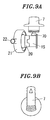
- the collar 15 is normally pressed against the rotating portion 20 by means of a spring 16 so that it can be engaged with the rotating portion 20 to transfer the rotational force of the connecting shaft 13 to the rotating portion 20. If the collar 15 is displaced away from the rotating portion 20 against the biasing force of the spring 16 as illustrated in FIG. 8, no rotational force is transmitted to the rotating portion 20, as a result of which the cylinder 3 is kept from any reciprocating movement and hence no striking force is applied to the output bit 50.
- reference numeral 70 designates a cam roller of the switching handle 7 for driving the collar 15.
- a striking-motion-activated mode can be shifted to a striking-motion-deactivated mode and vice versa regardless of the tightening torque adjusted.
- the hammer drill of the second preferred embodiment includes a mechanism for making the tightening-torque adjusting function inoperative in the striking-motion-activated mode by directly connecting the rotation transfer members through the use of the tightening-torque adjusting clutch 4.
- the mechanism includes a pin 8 for directly coupling the rotating body 40 serving as a driving member to the clutch plate 41 functioning as a driven member, a spring 80 for pressing the pin 8 toward a position where the direct coupling takes place, and a conversion plate 81 for pushing the pin 8 against the spring 80 into a release position where the direct coupling is released.
- the conversion plate 81 is adapted to interlock with the movement of the collar 15.
- the conversion plate 81 is caused to move backward so that the rotating body 40 and the clutch plate 41 can be directly coupled by means of the pin 8 as can be seen in FIG. 7A. If the collar 15 is displaced frontward out of engagement with the rotating portion 20, the conversion plate 81 is pressed by the collar 15 such that the rotating body 40 and the clutch plate 41 can make relative movement as illustrated in FIG. 7B.
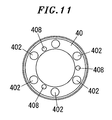
- the holes 402 formed through the rotating body 40 for receiving the steel balls 42 have a pitch circle differing from that of the holes 408 for accommodating the pin 8 and the spring 80 as clearly shown in FIG. 11. This prevents the pin 8 from any removal out of the engaging recesses of the clutch plate 41.
- FIGS. 12 through 15 illustrate a hammer drill in accordance with a third preferred embodiment of the present invention.
- the third preferred embodiment is the same as the second preferred embodiment in that the striking-motion-deactivated mode (see FIG. 13) is attained by interrupting the transfer of the rotational force between the rotating portion 20 and the collar 15, both of which cooperate to form an engaging clutch, and further in that the rotating body 40 and the clutch plate 41 of the tightening-torque adjusting clutch are directly coupled to each other by means of the pin 8 in the striking-motion-activated mode, i.e., hammer drill mode, (see FIG. 12).
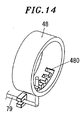
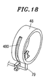
- a lever 79 is provided that interlocks with the axial movement of the collar 15. One end of the lever 79 is brought into engagement with an engaging groove 480 provided on the clutch handle 48.
- the engaging groove 480 is of a comb-like shape, i.e., has a portion extending in a circumferential direction of the clutch handle 48 and a plurality of axially extending portions.
- the lever 79 enters one of the axially extending portions ("X" in FIG. 15) of the engaging groove 480 and locks up the clutch handle 48 against any manipulation.
- the lever 79 is positioned in the circumferentially extending portion ("Y" in FIG. 15) of the engaging groove 480, thereby allowing the clutch handle 48 to be manually turned and making it possible to adjust the tightening torque.
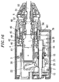
- FIGS. 16 through 19 illustrate a hammer drill in accordance with a fourth preferred embodiment of the present invention.
- the transfer of the rotational force between the rotating portion 20 and the collar 15 both forming the engaging clutch is interrupted in response to the manipulation of the clutch handle 48.
- the clutch handle 48 has a cam groove 481 with which one end of the lever 79 is engaged. Under a tightening torque adjustable condition, the lever 79 causes the collar 15 to be displaced away from the rotating portion 20 as illustrated in FIG. 17, thus inhibiting the reciprocating movement of the piston 30. In contrast, under a condition that the clutch handle 48 is turned to compress the clutch spring 45 to the maximum extent as shown in FIG. 16, the collar 15 is engaged with the rotating portion 20 to thereby transfer the rotational force to the motion conversion member 2.
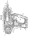
- FIGS. 20 through 28 illustrate a hammer drill in accordance with a fifth preferred embodiment of the present invention.
- the hammer drill of the fifth preferred embodiment is the same as that shown in FIGS. 5 through 11 in basic aspects. Description will be given in order regarding the hammer drill of this preferred embodiment.
- Reference numeral 9 in the drawings designates a housing with which a grip portion 90 is formed integrally so as to extend downwardly therefrom.
- a battery pack 91 is detachably attached to the bottom of the grip portion 90.
- a housing-reinforcing connecting portion 92 is integrally formed between the bottom frontal end of the grip portion 90 and the front end of the housing 9.
- Reference numeral 93 in the drawings designates a trigger switch disposed at a bottom portion of the grip portion 90.
- FIG. 26 is an exploded perspective view illustrating the tightening-torque adjusting clutch 4 employed in the hammer drill of the fifth preferred embodiment.
- the connecting shaft 13 is operatively connected to an output shaft 10 of the motor 19 through gears 11 and 12.
- the connecting shaft 13 is provided at its front end with the pinion 14 integrally formed therewith.
- the motion conversion member 2 is disposed at an intermediate part of the connecting shaft 13.
- the motion conversion member 2 includes the rotating portion 20 affixed to and rotatable with the connecting shaft 13 as a unit, the outer race 21 rotatably fitted to an inclined surface of the rotating portion 20, and the rod 22 protruding from the outer race 21.
- the rod 22 is connected to the piston 30 that can be moved within the cylinder 3 along an axial direction.
- the collar 15 that forms the engaging clutch in cooperation with the rotating portion 20 is provided on the connecting shaft 13 in such a fashion that the collar 15 can rotate with the connecting shaft 13 as a unit and also can be slid in an axial direction with respect to the connecting shaft 13.
- the collar 15 is pressed against the rotating portion 20 by means of the spring 16 into engagement with the rotating portion 20 to thereby transfer the rotational force of the connecting shaft 13 to the rotating portion 20.
- the rod 22 and the outer race 21 whose rotation about the connecting shaft 13 is restrained by the connection to the piston 30 are subjected to oscillating movement. This causes the piston 30 to reciprocate in its axial direction.
- the cylinder 3 is rotatable about it axis, on the outer circumferential surface of which the rotating body 40 having a gear meshed with the pinion 14 of the connecting shaft 13 is coupled for sliding movement in an axial direction of the cylinder 3 and also for rotational movement with respect to the cylinder 3.
- the clutch plate 41 is secured to the cylinder 3.
- the rotating body 40 is of a ring shape and has a plurality of axially penetrating holes into which the steel balls 42 are received.
- the clutch spring 45 is disposed to press a ball retainer (thrust plate) 44 against the steel balls 42. Pressing action of the clutch spring 45 brings the steel balls 42 into engagement with conical engaging recesses formed on the clutch plate 41.
- the rotating body 40 rotates about the axis of the cylinder 3 together with the clutch plate 41 as a unit, thereby ensuring that the rotational force of the connecting shaft 13 is transmitted to the cylinder 3 through the rotating body 40 and the clutch plate 41.
- the clutch spring 45 that makes contact with the ball retainer 44 at one end is supported at the other end by means of a movable plate 46 lying around the outer periphery of the cylinder 3.
- the movable plate 46 can be moved in an axial direction of the cylinder 3 to thereby change the level of compression of the clutch spring 45.
- the pin 8 for directly coupling the rotating body 40 serving as a driving member to the clutch plate 41 functioning as a driven member (see FIG. 22).
- the pin 8 is pressed by the spring 80 to protrude toward and engage with the clutch plate 41, the rotating body 40 and the clutch plate 41 are directly coupled to each other, thus ensuring that the rotational force of the rotating body 40 is always transferred to the clutch plate 41 and the cylinder 3.
- the conversion plate 81 is disposed around the outer circumference of the cylinder 3 in an axially movable manner. If the conversion plate 81 is pressed by the spring 82 to move forward, the distal end of the direct-coupling pin 8 is placed at a boundary surface of the rotating body 40 and the clutch plate 41 as illustrated in FIG. 20, thus releasing the direct coupling between the rotating body 40 and the clutch plate 41. At the time when the collar 15 is moved into engagement with the rotating portion 20, the conversion plate 81 is pressed by the collar 15 and moves backward against the spring 82, thus allowing the pin 8 to directly couple the rotating body 40 to the clutch plate 41.
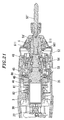
- the spindle 5 is attached to the axial front end of the cylinder 3 for unitary rotation with the cylinder 3.
- the spindle 5 is provided at its axial front end with the chuck portion 51 for holding the output bit 50".
- the chuck portion 51 which corresponds to an SDS-plus type shank, includes a removal-inhibiting ball 510 and a rotation-transferring internal protrusion 511 (see FIG. 21).
- the chuck portion 51 is designed to hold the output bit 50" in such a manner that the output bit 50" can be rotated with the chuck portion 51 as a unit while sliding axially within a predetermined range of movement.
- the piston 30 is of a cylindrical shape having a closed rear end and an opened front end.
- the striker 35 is slidably received within the piston 30.
- the striker 35 is also caused to reciprocate, at which time the air within the space of the piston 30 enclosed by the striker 35 plays a role of an air spring.
- the striker 35 applies a striking force to the output bit 50" in an axial direction through the intermediate member 52 axially slidably retained within the spindle 5.
- Reference numeral 56 in the drawings designates a ball for keeping the intermediate member 52 from backward removal out of the spindle 5.
- FIGS. 20 and 21 illustrate a striking-motion-deactivated mode, i.e., a condition devoted to screw tightening.
- the collar 15 is caused to move forward by the manipulation of the switching handle 7, thus releasing the engagement between the collar 15 and the rotating portion 20.
- the flange portion 150 of the collar 15 removes the pushing force applied to the conversion plate 81, in response to which the conversion plate 81 moves forward under the pressing force of the spring 85 to push the direct-coupling pin 8. This releases the direct coupling between the rotating body 40 and the clutch plate 41.
- the rotational force that the rotating body 40 receives from the pinion 14 of the connecting shaft 13 is transferred to the spindle 5 through the steel balls 42, the clutch plate 41 and the cylinder 3.
- the O-ring 58 disposed on the rear inner circumference of the spindle 5 is resiliently engaged with the front outer circumference of the striker 35, thereby preventing the striker 35 and the intermediate member 52 from any axial movement. Accordingly, no inadvertent movement is caused to the striker 35 and the intermediate member 52.
- the tightening torque can be increased by turning the clutch handle 48 as set forth above and displacing the movable plate 46 backward to increase the level of compression of the clutch spring 45.
- the steel balls 42 is kept in a condition that it cannot be escaped from the engaging recesses. This condition is suitable for what is called a drilling work.
- the reciprocating movement of the piston 30 leads to the reciprocating movement of the striker 35, which means that the striker 35 is in condition for applying a striking force to the output bit 50" in an axial direction through the intermediate member 52. This makes sure that the rotational force and the axial striking force are transferred to the output bit 50".
- the switching handle 7 is adapted to displace the collar 15 out of engagement with the rotating portion 20.
- the pressing force of the spring 16 is used in causing the collar 15 to move toward and smoothly engage with the rotating portion 20.
- the spring 16 is designed to have a pressing force greater than that of the spring 82 for pressing the conversion plate 81. Furthermore, the pressing force of the spring 82 is greater than that of the spring 80 for pressing the direct-coupling pin 8.
- an output bit 50" as a drill bit or a driver bit is provided with no SDS-plus type shank for use with the hammer drill and therefore is mounted with the use of an adapter 50' having the SDS-plus type shank.
- the SDS-plus type shank employed in the adapter 50' differs somewhat from a typical SDS-plus type shank shown in FIG. 27B.
- the SDS-plus type shank of the adapter 50' is the same as the typical SDS-plus type shank in that the adapter 50' has an insertion groove 500 for engagement with the removal-inhibiting ball 510 and a slide groove 501 with which the rotation-transferring internal protrusion 511 is slidingly engaged.
- a distinctive feature of the adapter 50' resides in that the axial length of the slide groove 501 measured from the rear end of the shank is short. In other words, at the time of mounting the adapter 50' into the chuck portion 51, the depth of insertion of the adapter 50' is restrained by the stopping action of the internal protrusion 511. This prevents the adapter 50' from moving backward into contact with the front end of the intermediate member 52 at its rear end.
- the output bit 50" such as a drill bit or a driver bit
- the adapter 50' in the striking-motion-activated mode, i.e., hammer drill mode, where the rotational force and the striking force are applied jointly, there is no possibility that the striking force is applied to the adapter 50'.
- the adapter 50', the output bit 50 such as a drill bit or a driver bit, and the screw or the like in contact with the distal end of the output bit 50" are damaged by the striking vibration.
- the striker 35 continues to be retained in position by means of the O-ring 58 for the reasons noted above.
- the output bit 50 As the output bit 50", a hammer drill bit having the typical SDS-plus type shank illustrated in FIG. 27B is mounted to the chuck portion 51, the output bit 50" can be moved backward to such an extent that the rear end of the output bit 50" makes contact with the intermediate member 52. Furthermore, the striker 35 can be displaced backward through the intermediate member 52 beyond the position where the striker 35 is retained in place by means of the O-ring 58, in which condition the striking force as well as the rotational force is applied to the output bit 50".
- the slide groove 501 of the adapter 50' differs not only in length but also in inner end shape from that of the typical shank.
- the internal protrusion 511 has a front end comprised of a flat inclined surface. For this reason, if the front end of the internal protrusion 511 makes contact with the inner end of the slide groove 501 of the typical shank shown in FIG. 27A, the side edges of the inner end of the slide groove 501 are cut away.
- the slide groove 501 of the adapter 50' is designed to have a slant inner end surface 502 capable of making surface-to-surface contact with the front end of the internal protrusion 511.
- the adapter 50' may be stored, when not in use, within a holder portion 95 provided in the connecting portion 92 of the housing 9.
- the holder portion 95 is in the form of a recessed space opened to one side of the connecting portion 92.
- the holder portion 95 has a spring plate 950 for retaining the shank portion of the adapter 50', an enlarged recess part 952 for receiving the large diameter chuck portion of the adapter 50', and a void part 953 for accommodating the output bit 50" when the adapter 50' is stored with the output bit 50" attached thereto.
- the connecting portion 95 has a reduced thickness to provide an access space 951 through which the fingers of a user gain access to the large diameter chuck portion of the adapter 50' to take out the adapter 50'.
- the front end of the output bit 50" is inserted into the void part 953 as illustrated in FIG. 25D, after which the large diameter chuck portion of the adapter 50' is received within the enlarged recess part 952 and the shank portion of the adapter 50' is pushed into the seat portion of the spring plate 950.
- the above-noted storing operations are conducted in the reverse order to take out the adapter 50'.
- the output bit 50" may be contacted with the side wall edge 955 of the connecting portion 92 to thereby scratch or damage the edge 955. For this reason, it is desirable to provide a reinforcing rib 954 on the side wall of the connecting portion 92 as illustrated in FIG. 28.
- the connecting portion 92 is shaped not to protrude forward over a line joining the lower end of the battery pack 91 and the front end of the hammer drill (see FIG. 24). This is to prevent any damage of the connecting portion 92 which would otherwise be caused by the shock when the hammer drill is inadvertently fallen in the frontward direction.
- the hammer drill in accordance with the present invention performs an operating mode where a rotational force alone is transferred to an output bit, while allowing a user to control a screw tightening torque with the use of a tightening-torque adjusting clutch.
- This makes it possible for a single hammer drill to carry out two kinds of works, namely, a task of drilling an object member, such as a concrete structure or the like, and a task of tightening a screw.
Applications Claiming Priority (2)
| Application Number | Priority Date | Filing Date | Title |
|---|---|---|---|
| JP2005154701 | 2005-05-26 | ||
| JP2005357011A JP4702027B2 (ja) | 2005-05-26 | 2005-12-09 | ハンマードリル |
Publications (3)
| Publication Number | Publication Date |
|---|---|
| EP1726407A2 true EP1726407A2 (fr) | 2006-11-29 |
| EP1726407A3 EP1726407A3 (fr) | 2008-10-22 |
| EP1726407B1 EP1726407B1 (fr) | 2013-07-10 |
Family
ID=36809111
Family Applications (1)
| Application Number | Title | Priority Date | Filing Date |
|---|---|---|---|
| EP06010930.3A Active EP1726407B1 (fr) | 2005-05-26 | 2006-05-26 | Marteau perforateur |
Country Status (3)
| Country | Link |
|---|---|
| US (2) | US7694750B2 (fr) |
| EP (1) | EP1726407B1 (fr) |
| JP (1) | JP4702027B2 (fr) |
Cited By (4)
| Publication number | Priority date | Publication date | Assignee | Title |
|---|---|---|---|---|
| EP1795307A2 (fr) * | 2005-12-09 | 2007-06-13 | Matsushita Electric Works, Ltd. | Adaptateur pour un outil à impact motorisé |
| WO2009053141A1 (fr) * | 2007-10-24 | 2009-04-30 | Robert Bosch Gmbh | Machine-outil à main |
| US7694750B2 (en) * | 2005-05-26 | 2010-04-13 | Panasonic Electric Works Co., Ltd. | Hammer drill |
| EP2448716B1 (fr) * | 2009-07-03 | 2018-02-21 | Robert Bosch GmbH | Machine-outil portative |
Families Citing this family (12)
| Publication number | Priority date | Publication date | Assignee | Title |
|---|---|---|---|---|
| US20090229397A1 (en) * | 2008-03-16 | 2009-09-17 | Ting-Kuang Chen | Protection Device For Speed Shifting Mechanism |
| US8251158B2 (en) | 2008-11-08 | 2012-08-28 | Black & Decker Inc. | Multi-speed power tool transmission with alternative ring gear configuration |
| GB2472227B (en) * | 2009-07-29 | 2011-09-14 | Mobiletron Electronics Co Ltd | Impact drill |
| JP5479023B2 (ja) * | 2009-10-20 | 2014-04-23 | 株式会社マキタ | 充電式電動工具 |
| JP2012135845A (ja) * | 2010-12-27 | 2012-07-19 | Makita Corp | 作業工具 |
| EP3636389A1 (fr) | 2012-02-03 | 2020-04-15 | Milwaukee Electric Tool Corporation | Marteau rotatif |
| US9908228B2 (en) * | 2012-10-19 | 2018-03-06 | Milwaukee Electric Tool Corporation | Hammer drill |
| KR101453891B1 (ko) * | 2013-02-26 | 2014-11-03 | 계양전기 주식회사 | 임팩트 전동공구 및 제어방법 |
| EP2821183B1 (fr) | 2013-07-05 | 2017-06-21 | Black & Decker Inc. | Marteau perforateur |
| US10406667B2 (en) * | 2015-12-10 | 2019-09-10 | Black & Decker Inc. | Drill |
| EP3670097A1 (fr) * | 2018-12-21 | 2020-06-24 | Hilti Aktiengesellschaft | Machine-outil portative |
| WO2022246207A1 (fr) * | 2021-05-21 | 2022-11-24 | Milwaukee Electric Tool Corporation | Marteau burineur |
Citations (1)
| Publication number | Priority date | Publication date | Assignee | Title |
|---|---|---|---|---|
| US3828863A (en) | 1972-08-31 | 1974-08-13 | Bosch Gmbh Robert | Combined portable electric impact wrench and chipping hammer |
Family Cites Families (29)
| Publication number | Priority date | Publication date | Assignee | Title |
|---|---|---|---|---|
| DE2328462C2 (de) * | 1973-06-05 | 1985-08-29 | Robert Bosch Gmbh, 7000 Stuttgart | Schlagbohrmaschine |
| DE3205141A1 (de) * | 1982-02-13 | 1983-08-18 | Robert Bosch Gmbh, 7000 Stuttgart | Bohrhammer |
| JPH0630846B2 (ja) * | 1985-03-25 | 1994-04-27 | 松下電工株式会社 | 衝撃工具 |
| JPH0616993B2 (ja) * | 1985-09-25 | 1994-03-09 | 松下電工株式会社 | 電動工具 |
| DE3627869A1 (de) | 1986-08-16 | 1988-02-18 | Bosch Gmbh Robert | Schlagwerkabschaltung |
| JPH04105883A (ja) * | 1990-08-28 | 1992-04-07 | Matsushita Electric Works Ltd | 振動ドリル |
| DE4100185A1 (de) * | 1991-01-05 | 1992-07-09 | Bosch Gmbh Robert | Handwerkzeugmaschine mit sicherheitskupplung |
| US5320177A (en) * | 1992-03-30 | 1994-06-14 | Makita Corporation | Power driven hammer drill |
| JPH071355A (ja) * | 1993-06-16 | 1995-01-06 | Makita Corp | トルク感応型可変クラッチ付回転工具 |
| JPH0680573U (ja) * | 1993-04-23 | 1994-11-15 | 日立工機株式会社 | 打撃工具 |
| US5588496A (en) * | 1994-07-14 | 1996-12-31 | Milwaukee Electric Tool Corporation | Slip clutch arrangement for power tool |
| DE19545260A1 (de) * | 1995-11-24 | 1997-05-28 | Black & Decker Inc | Bohrhammer |
| JP3655481B2 (ja) * | 1999-02-15 | 2005-06-02 | 株式会社マキタ | 震動ドライバドリル |
| US6142242A (en) * | 1999-02-15 | 2000-11-07 | Makita Corporation | Percussion driver drill, and a changeover mechanism for changing over a plurality of operating modes of an apparatus |
| JP3683754B2 (ja) * | 1999-10-05 | 2005-08-17 | 株式会社マキタ | ハンマードリル |
| DE10009918A1 (de) | 2000-03-01 | 2001-09-06 | Bayerische Motoren Werke Ag | Hydraulisches Stabilisierungssystem |
| DE10106034B4 (de) | 2001-02-09 | 2009-11-26 | Robert Bosch Gmbh | Handwerkzeugmaschine |
| DE10121088A1 (de) * | 2001-04-28 | 2002-11-07 | Bosch Gmbh Robert | Bohr- und/oder Meißelhammer |
| DE10122820A1 (de) * | 2001-05-11 | 2002-11-21 | Bosch Gmbh Robert | Handwerkzeugmaschine |
| JP4161580B2 (ja) * | 2002-01-28 | 2008-10-08 | 松下電工株式会社 | 振動ドリルドライバ |
| WO2004020156A1 (fr) * | 2002-08-27 | 2004-03-11 | Matsushita Electric Works, Ltd. | Perceuse/visseuse electrique vibrante |
| JP4243093B2 (ja) * | 2002-11-20 | 2009-03-25 | 株式会社マキタ | 電動ハンマ |
| TW554792U (en) * | 2003-01-29 | 2003-09-21 | Mobiletron Electronics Co Ltd | Function switching device of electric tool |
| DE10337260A1 (de) * | 2003-08-18 | 2005-03-10 | Bosch Gmbh Robert | Bedienungsmodul für eine Elektrowerkzeugmaschine |
| DE102004018084B3 (de) * | 2004-04-08 | 2005-11-17 | Hilti Ag | Hammerbohrgerät |
| JP4702027B2 (ja) * | 2005-05-26 | 2011-06-15 | パナソニック電工株式会社 | ハンマードリル |
| JP2007160420A (ja) * | 2005-12-09 | 2007-06-28 | Matsushita Electric Works Ltd | 打撃工具 |
| JP4552843B2 (ja) * | 2005-12-09 | 2010-09-29 | パナソニック電工株式会社 | 打撃工具用アダプター |
| US7168503B1 (en) * | 2006-01-03 | 2007-01-30 | Mobiletron Electronics Co., Ltd. | Power hand tool |
-
2005
- 2005-12-09 JP JP2005357011A patent/JP4702027B2/ja active Active
-
2006
- 2006-05-26 EP EP06010930.3A patent/EP1726407B1/fr active Active
- 2006-05-26 US US11/441,141 patent/US7694750B2/en active Active
-
2009
- 2009-05-27 US US12/472,988 patent/US7828074B2/en active Active
Patent Citations (1)
| Publication number | Priority date | Publication date | Assignee | Title |
|---|---|---|---|---|
| US3828863A (en) | 1972-08-31 | 1974-08-13 | Bosch Gmbh Robert | Combined portable electric impact wrench and chipping hammer |
Cited By (6)
| Publication number | Priority date | Publication date | Assignee | Title |
|---|---|---|---|---|
| US7694750B2 (en) * | 2005-05-26 | 2010-04-13 | Panasonic Electric Works Co., Ltd. | Hammer drill |
| US7828074B2 (en) | 2005-05-26 | 2010-11-09 | Panasonic Electric Works Co., Ltd. | Hammer drill |
| EP1795307A2 (fr) * | 2005-12-09 | 2007-06-13 | Matsushita Electric Works, Ltd. | Adaptateur pour un outil à impact motorisé |
| EP1795307A3 (fr) * | 2005-12-09 | 2007-06-20 | Matsushita Electric Works, Ltd. | Adaptateur pour un outil à impact motorisé |
| WO2009053141A1 (fr) * | 2007-10-24 | 2009-04-30 | Robert Bosch Gmbh | Machine-outil à main |
| EP2448716B1 (fr) * | 2009-07-03 | 2018-02-21 | Robert Bosch GmbH | Machine-outil portative |
Also Published As
| Publication number | Publication date |
|---|---|
| US20060266536A1 (en) | 2006-11-30 |
| JP2007000999A (ja) | 2007-01-11 |
| EP1726407A3 (fr) | 2008-10-22 |
| JP4702027B2 (ja) | 2011-06-15 |
| US7694750B2 (en) | 2010-04-13 |
| US7828074B2 (en) | 2010-11-09 |
| EP1726407B1 (fr) | 2013-07-10 |
| US20090229845A1 (en) | 2009-09-17 |
Similar Documents
| Publication | Publication Date | Title |
|---|---|---|
| EP1726407B1 (fr) | Marteau perforateur | |
| EP1795311A2 (fr) | Outil à impact motorisé | |
| EP1832391B1 (fr) | Adapteur d'outil pour un outil électrique | |
| EP1795307A2 (fr) | Adaptateur pour un outil à impact motorisé | |
| JP3292972B2 (ja) | 打撃工具 | |
| US7096972B2 (en) | Hammer drill attachment | |
| US6913090B2 (en) | Hammer | |
| EP1574294B1 (fr) | Dispositif de commande à percussion | |
| US7987920B2 (en) | Multi-mode drill with mode collar | |
| US7654779B2 (en) | Power tool | |
| EP1759792B1 (fr) | Outil motorisé avec système de mandrin avec verrouillage de la broche et manchon coulissant | |
| US7735575B2 (en) | Hammer drill with hard hammer support structure | |
| US6497418B2 (en) | Tool-bit holding device in percussion tool | |
| JPH07185913A (ja) | 手持ち式工作機械に設けられた、工具を回転連行するための装置 | |
| JP5055749B2 (ja) | ハンマドリル | |
| JPH0957652A (ja) | ハンマードリル | |
| US20090065228A1 (en) | Power impact tool | |
| CN100420531C (zh) | 锤钻 | |
| US20030116334A1 (en) | Chuck for a percussion tool | |
| CN210998437U (zh) | 手持工具 | |
| GB2085795A (en) | A hammer drill | |
| JP4458035B2 (ja) | 電動工具 | |
| JP2006187836A (ja) | ハンマドリル |
Legal Events
| Date | Code | Title | Description |
|---|---|---|---|
| PUAI | Public reference made under article 153(3) epc to a published international application that has entered the european phase |
Free format text: ORIGINAL CODE: 0009012 |
|
| AK | Designated contracting states |
Kind code of ref document: A2 Designated state(s): AT BE BG CH CY CZ DE DK EE ES FI FR GB GR HU IE IS IT LI LT LU LV MC NL PL PT RO SE SI SK TR |
|
| AX | Request for extension of the european patent |
Extension state: AL BA HR MK YU |
|
| PUAL | Search report despatched |
Free format text: ORIGINAL CODE: 0009013 |
|
| RIC1 | Information provided on ipc code assigned before grant |
Ipc: B25D 16/00 20060101AFI20060912BHEP Ipc: B25B 23/14 20060101ALI20080829BHEP |
|
| AK | Designated contracting states |
Kind code of ref document: A3 Designated state(s): AT BE BG CH CY CZ DE DK EE ES FI FR GB GR HU IE IS IT LI LT LU LV MC NL PL PT RO SE SI SK TR |
|
| AX | Request for extension of the european patent |
Extension state: AL BA HR MK YU |
|
| RAP1 | Party data changed (applicant data changed or rights of an application transferred) |
Owner name: PANASONIC ELECTRIC WORKS CO., LTD. |
|
| 17P | Request for examination filed |
Effective date: 20090121 |
|
| AKX | Designation fees paid |
Designated state(s): DE FR GB |
|
| 17Q | First examination report despatched |
Effective date: 20091013 |
|
| RAP1 | Party data changed (applicant data changed or rights of an application transferred) |
Owner name: PANASONIC CORPORATION |
|
| RIC1 | Information provided on ipc code assigned before grant |
Ipc: B25B 23/14 20060101ALI20120229BHEP Ipc: B25D 17/08 20060101ALN20120229BHEP Ipc: B25D 17/06 20060101ALN20120229BHEP Ipc: B25D 11/06 20060101ALN20120229BHEP Ipc: B25D 16/00 20060101AFI20120229BHEP |
|
| RIC1 | Information provided on ipc code assigned before grant |
Ipc: B25D 16/00 20060101AFI20121115BHEP Ipc: B25D 17/06 20060101ALN20121115BHEP Ipc: B25B 23/14 20060101ALI20121115BHEP Ipc: B25D 17/08 20060101ALN20121115BHEP Ipc: B25D 11/06 20060101ALN20121115BHEP |
|
| RIC1 | Information provided on ipc code assigned before grant |
Ipc: B25D 17/08 20060101ALN20121116BHEP Ipc: B25D 11/06 20060101ALN20121116BHEP Ipc: B25D 16/00 20060101AFI20121116BHEP Ipc: B25D 17/06 20060101ALN20121116BHEP Ipc: B25B 23/14 20060101ALI20121116BHEP |
|
| GRAP | Despatch of communication of intention to grant a patent |
Free format text: ORIGINAL CODE: EPIDOSNIGR1 |
|
| GRAS | Grant fee paid |
Free format text: ORIGINAL CODE: EPIDOSNIGR3 |
|
| GRAA | (expected) grant |
Free format text: ORIGINAL CODE: 0009210 |
|
| AK | Designated contracting states |
Kind code of ref document: B1 Designated state(s): DE FR GB |
|
| REG | Reference to a national code |
Ref country code: GB Ref legal event code: FG4D |
|
| REG | Reference to a national code |
Ref country code: DE Ref legal event code: R096 Ref document number: 602006037194 Country of ref document: DE Effective date: 20130912 |
|
| PLBE | No opposition filed within time limit |
Free format text: ORIGINAL CODE: 0009261 |
|
| STAA | Information on the status of an ep patent application or granted ep patent |
Free format text: STATUS: NO OPPOSITION FILED WITHIN TIME LIMIT |
|
| 26N | No opposition filed |
Effective date: 20140411 |
|
| REG | Reference to a national code |
Ref country code: DE Ref legal event code: R097 Ref document number: 602006037194 Country of ref document: DE Effective date: 20140411 |
|
| REG | Reference to a national code |
Ref country code: FR Ref legal event code: PLFP Year of fee payment: 11 |
|
| REG | Reference to a national code |
Ref country code: FR Ref legal event code: PLFP Year of fee payment: 12 |
|
| REG | Reference to a national code |
Ref country code: FR Ref legal event code: PLFP Year of fee payment: 13 |
|
| PGFP | Annual fee paid to national office [announced via postgrant information from national office to epo] |
Ref country code: FR Payment date: 20200522 Year of fee payment: 15 |
|
| PGFP | Annual fee paid to national office [announced via postgrant information from national office to epo] |
Ref country code: GB Payment date: 20210520 Year of fee payment: 16 |
|
| PG25 | Lapsed in a contracting state [announced via postgrant information from national office to epo] |
Ref country code: FR Free format text: LAPSE BECAUSE OF NON-PAYMENT OF DUE FEES Effective date: 20210531 |
|
| GBPC | Gb: european patent ceased through non-payment of renewal fee |
Effective date: 20220526 |
|
| PG25 | Lapsed in a contracting state [announced via postgrant information from national office to epo] |
Ref country code: GB Free format text: LAPSE BECAUSE OF NON-PAYMENT OF DUE FEES Effective date: 20220526 |
|
| PGFP | Annual fee paid to national office [announced via postgrant information from national office to epo] |
Ref country code: DE Payment date: 20230519 Year of fee payment: 18 |