EP1724449A1 - Serviceeinheit zur Betriebsmittelergänzung - Google Patents
Serviceeinheit zur Betriebsmittelergänzung Download PDFInfo
- Publication number
- EP1724449A1 EP1724449A1 EP06004100A EP06004100A EP1724449A1 EP 1724449 A1 EP1724449 A1 EP 1724449A1 EP 06004100 A EP06004100 A EP 06004100A EP 06004100 A EP06004100 A EP 06004100A EP 1724449 A1 EP1724449 A1 EP 1724449A1
- Authority
- EP
- European Patent Office
- Prior art keywords
- service unit
- unit according
- drip
- protection cover
- tray
- Prior art date
- Legal status (The legal status is an assumption and is not a legal conclusion. Google has not performed a legal analysis and makes no representation as to the accuracy of the status listed.)
- Granted
Links
Images


Classifications
-
- B—PERFORMING OPERATIONS; TRANSPORTING
- B62—LAND VEHICLES FOR TRAVELLING OTHERWISE THAN ON RAILS
- B62D—MOTOR VEHICLES; TRAILERS
- B62D25/00—Superstructure or monocoque structure sub-units; Parts or details thereof not otherwise provided for
- B62D25/24—Superstructure sub-units with access or drainage openings having movable or removable closures; Sealing means therefor
-
- F—MECHANICAL ENGINEERING; LIGHTING; HEATING; WEAPONS; BLASTING
- F01—MACHINES OR ENGINES IN GENERAL; ENGINE PLANTS IN GENERAL; STEAM ENGINES
- F01P—COOLING OF MACHINES OR ENGINES IN GENERAL; COOLING OF INTERNAL-COMBUSTION ENGINES
- F01P11/00—Component parts, details, or accessories not provided for in, or of interest apart from, groups F01P1/00 - F01P9/00
- F01P11/02—Liquid-coolant filling, overflow, venting, or draining devices
- F01P11/0204—Filling
-
- F—MECHANICAL ENGINEERING; LIGHTING; HEATING; WEAPONS; BLASTING
- F01—MACHINES OR ENGINES IN GENERAL; ENGINE PLANTS IN GENERAL; STEAM ENGINES
- F01P—COOLING OF MACHINES OR ENGINES IN GENERAL; COOLING OF INTERNAL-COMBUSTION ENGINES
- F01P11/00—Component parts, details, or accessories not provided for in, or of interest apart from, groups F01P1/00 - F01P9/00
- F01P11/02—Liquid-coolant filling, overflow, venting, or draining devices
- F01P11/0204—Filling
- F01P11/0209—Closure caps
- F01P11/0247—Safety; Locking against opening
Definitions
- a generic service unit for equipment supplementation or maintenance / inspection on a vehicle with a prime mover as an aggregate can post-published DE 103 59 767 be removed.
- This service unit is preferably arranged inside the vehicle, for example in the luggage compartment, and has a filler neck as a service element for the supplement of equipment, for example for the cooling fluid of the drive machine, and a collecting bowl at least partially surrounding the filler neck, which serves to catch liquid spilled during the supplementing of the equipment and preferably via a drain.
- the object of the invention is to provide a service unit of the type mentioned, with the equipment supplement or maintenance can be simplified.
- the advantages achieved by the invention are to be seen in the fact that in a carried out via the service unit equipment supplement possibly spilled or leaking liquid can be better collected and discharged into the drip tray. Furthermore, possibly emerging from the service element steam, which condenses on the drip tray or on the drip protection cover, are derived. If the service unit is associated, for example, with a dipstick, in particular an oil dipstick, liquid dripping from the dipstick can be collected via the drip protection cover during fill level control. The surrounding the drip tray or service unit Vehicle areas are thus protected in a simple manner from contamination.
- this service unit according to the invention can be used in a motor vehicle in which the service unit is arranged in the vehicle interior or luggage compartment. Contamination of the service unit surrounding interior trim parts of the motor vehicle can thus be prevented in most cases.
- the drip protection cover can cover a large surface area by the unfolding into the protective position.
- the drip protection cover can be firmly connected to the attachment portion with the drip tray, so that only the folding portion of the drip protection cover can be transferred by unfolding into the protective position.
- the drip protection cover can be realized with the folding section in a particularly simple manner.
- a simple attachment of the drip protection cover to the drip tray is specified in claim 7. Due to the design of the connecting means as a grip element, the drip protection cover can be hung on the drip tray, clipped or knotted. By the engagement element also the breakthrough in the drip tray is sealed.
- the connecting means can be connected in a particularly simple manner, in particular in the embodiment as a rear grip element, with the drip tray.
- an improved protection with the drip protection cover can be achieved since spilled or escaping liquid or rapidly condensing vapor can not flow off laterally beyond the drip protection cover, since the side walls are provided.
- the drip protection cover can be unfolded in an advantageous manner and fold again for the transfer to the rest position.
- the fold lines can be realized, for example, by weakened sections in the material of the anti-drip cover, so that film hinges are formed.
- the attachment portion may extend over a wide range of the inner edge contour of the drip tray and also bear sealingly against the inner edge contour.
- the fastening section according to claim 15 is advantageously formed.
- the drip tray therefore has an oval, angular or similar edge contour on which partially runs the attachment portion with its base and the side arms along.
- an embodiment of the drip protection cover can be realized in which the drip protection cover is designed shell-like in its protective position, however, can be folded in a simple manner in the rest position.
- a plurality of engagement elements are provided as a connecting means, as indicated in claim 17.
- the seal between drip tray and anti-drip cover is thus further optimized.
- a cover of the service unit or the drip tray is possible with a cover provided according to claim 18.
- a high ease of use results in a specified in claim 19 embodiment, according to which the drip protection cover can be unfolded automatically from the rest position to the protection position.
- a particularly favorable arrangement, possibly also at an optically exposed point, within the vehicle can be achieved with the embodiment specified in claim 20.
- Fig. 1 shows a service unit 1 for supplementation and / or maintenance and / or control of at least one operating means for at least one unit, in particular a drive machine (not shown) for a motor vehicle not shown here in detail.
- Such resources may in particular liquids, such as For example, be fuel, coolant, lubricating oil, hydraulic oil, power steering fluid, refrigerant for an air conditioner or the like.
- the service unit 1 therefore has at least one service element for carrying out the supplementation, maintenance or control on the unit.
- This service element can thus be embodied as a dipstick, in particular an oil dipstick, a test opening, a sight glass which may be removable, a connecting piece, in particular a valve (possibly an overpressure or filling valve), a filler neck 2 or the like.
- a resource of the unit can leak and / or filled and / or controlled via this service element.
- two service elements are provided, which are realized as filling nozzles 2 and 3, of which in particular the filling nozzle 2 for the filling of lubricant of the drive machine and the filling nozzle 3 is used for filling the cooling circuit for the drive machine.
- further service elements of the service unit 1 can be assigned.
- the at least one filling nozzle 2 or 3 or the service element is at least partially surrounded by a collecting tray 4 which has a tray bottom 5, which can be provided with a drain 6 in the tray bottom 5 itself or in a transition region 7 between the tray bottom. 5 and a shell wall 8 or in the shell wall 8 itself may be formed. From the shell bottom 5, the circumferential, approximately upright shell wall 8 goes out, which has an inner edge contour 9, which is for example oval, circular, rectangular, optionally with rounded corners, or similar executed.
- the collecting tray 4 preferably has with its shell wall 8 an inner width such that the shell wall 8 is at a distance from the filling nozzles 2, 3 or the closure caps 10 placed thereon.
- the filling nozzle 2 may be provided with a closure cap 10.
- the shell wall 8 forms, with its free wall end 11, a circumferential shell edge 12 which comprises a lower edge section 13, an upper edge section 14 and two lateral edge sections 15 and 16.
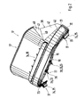
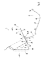
- the drip tray 4 is associated with at least one Drip protection cover 17, which - as shown in particular in FIG. 4 - can lie in a rest position RS within the drip tray 4 or within the service unit 1 and - as can be seen in Figs. 1 and 3 - in an unfolded, the shell edge 12 superior protective position ST can be moved.
- the drip protection cover 17 forms an extension of the shell wall 8, so that over an enlarged protection area catching spilled liquid in the resource supplement via the service element or from the service element leaking liquid or exiting and rapidly condensing steam the maintenance or control over the service element is given.
- the drip protection cover 17 In order to be able to transfer the drip protection cover 17 from the rest position RS into the protective position ST, it can be transferred, as mentioned above, from the folded rest position RS into the unfolded protective position ST.
- the drip protection cover 17 is assigned to the lower edge section 13 of the shell edge 12 and, in addition, adapted to the inner edge contour 9 of the shell wall 8, in particular, it bears against the shell wall 8 in a sealing manner.
- Within the drip tray 4 is a mounting portion 18 of the drip guard 17.
- This mounting portion 18 is executed in a preferred embodiment approximately U-shaped and thus has a base 19 which is associated with the lower edge portion 13; it further comprises lateral arms 20 and 21 which extend from the base 19 and extend at least partially inwardly along the lateral edge portions 15 and 16.
- the attachment portion 18 may extend to the shell bottom 5 and in particular into the transition region 7 and it may sealingly abut against the shell bottom 5 and the shell wall 8.
- the attachment portion 18 can be provided with a region 18 'tapering in the direction of its free end, which thus forms a sealing lip, as can be seen in FIG. 4.
- the attachment portion 18 has a connection means 22 for attaching the drip protection cover 17 to the drip tray 4, as shown in FIGS. 2 and 3 evident.
- the connecting means 22 comprises one or more fastening elements 23, 24, which are formed as a rear grip elements 25 and each cooperate with a corresponding formed in the drip tray 4 opening 26, respectively, pass through this opening 26 and engage behind the outside 27 of the drip tray 4.
- the or the fastening elements 23 are designed as so-called mushroom pin 28, which pass through the respective opening 26 with its foot 29 and come to rest with its mushroom head 30 on the outside 27 sealingly.
- the fastening elements 24 are formed as elongated webs 31, each having a web foot 32, which, like the foot 29 of the mushroom pin 28, passes through a corresponding opening in the drip tray.
- the connecting means 22 may still have a Aufsteckabêt 34, which is designed as a pocket 35 which is attachable to the shell edge 12, as can be seen in particular in Fig. 3.
- the drip protection cover 17 can be easily clipped onto the drip tray 4, hooked in and thus fastened.
- the rear grip elements 25 of the connecting means 22 are distributed on the base 19 and the lateral arms 20 and 21 of the mounting portion 18.
- the mushroom pin 28 of the base 19 and the webs 31 are associated with the lateral arms 20 and 21.
- a folding portion 36 of the drip protection cover 17 connects.
- the folding portion 36 projects beyond the shell wall 18 in the protective position ST and thus forms a trough-shaped or funnel-shaped collecting element for spilled or leaked equipment.
- For the execution in trough shape of the folding portion 36 has a bottom 37 and side walls 38 and 39.
- the fold line is achieved in a preferred embodiment by a material weakening or a cut, so that a film hinge is formed on the fold line 40.
- the folding section 36 can be folded in the direction of the collecting tray 4, as can be clearly seen in FIG. 4.
- the folding section 36 is connected to the fastening section via a plurality of fold lines 40, ie, one fold line 40 is provided between the base 37 and the fastening section 18 and one fold line 40 is provided between the side walls 38 and 39 and the fastening section 18.
- one fold line 40 is provided between the base 37 and the base 19
- one fold line 40 is provided between the side walls 38 and 39 and the fastening section 18.
- the folding section 36 is foldable in itself, for which further fold lines 40 are provided between the side walls 38 and 39 and the base 37.
- the side walls 38 and 39 may be foldable, so that each side wall 38 and 39 has at least two part walls 41 and 42, which are each connected to each other via a further fold line 40.
- the partial walls 41 and 42 each have an approximately triangular shape, as can be seen in particular from FIG. 2 for the side wall 38.
- the drip protection cover 17 can be made in one piece in a particularly simple manner, in particular provided to make the drip protection cover 17 made of an elastic material ,
- an elastomer preferably a thermoplastic elastomer (TPE) is used, which has a hardness of 50 +/- 5 Shore A, for example.
- TPE thermoplastic elastomer
- Such a thermoplastic elastomer is available, for example, under the trade name Santoprene®.
- the drip protection cover 17 is shown in its manufactured form, that is, that the drip protection cover is made unfolded. Will the Tropfterrorismabdeckung 17 then - as Fig. 4 shows - folded folded into the rest position RS, it is biased by the use of the elastic material in the direction of their protective position ST, so that an automatic unfolding of the anti-drip cover 17 is given.
- the automatic unfolding of the drip protection cover 17 is particularly advantageous when the service unit 17 is provided with a cover 43 closing the drip tray 4, which is removable from the drip tray 4 and put back.
- the cover 43 is preferably mounted parallel to the lower edge section 13 and underneath this edge section 13 about a pivot axis (not shown), so that it pivots, starting from its closed position GS shown in FIG.
- the cover 43 may be pivotally hinged to an adjacent inner trim part 44 accordingly. It would also be conceivable that the lid 43 is removable and replaceable only from the collecting tray 4, so has no fixed connection. With appropriate articulation of the lid 43, and in particular in its articulation on the collecting tray 4, it would be conceivable that the drip protection cover 17 could alternatively be attached to the inner lid side 45, so that a folding out of the folding portion 36 would be given in the direction of the lower edge portion 13.
- the service unit 1 is associated with a body wall 46, which separates an aggregate space, in particular engine compartment 47 for the engine of a vehicle interior 48, in particular luggage compartment.
- the body wall 46 may be substantially upright and the service unit 1 can the Vehicle interior 48 to be assigned. Attached is the service unit 1 on the body wall 46 via a mounting frame 49. In this case, the service unit or the collecting tray 4 - relative to the tray bottom 4 - upright or inclined aligned with the mounting frame 49 held.
- the edge portion 13 thus forms the lower portion of the shell edge 12th
- the drip protection cover 17 may be funnel-shaped in the protective position ST.
- the shell wall 8 could be equipped with two drip guards 17 such that it rotates in the protective position ST along the shell wall 8.
- the drip protection cover 17 is located with its folding portion 36 in the rest position RS within the limited by the drip tray and the lid 43 space of the service unit 1.
- the folding section 36 can at least partially be folded into the collecting tray 4.
Landscapes
- Engineering & Computer Science (AREA)
- Chemical & Material Sciences (AREA)
- Combustion & Propulsion (AREA)
- Mechanical Engineering (AREA)
- Transportation (AREA)
- General Engineering & Computer Science (AREA)
- Cooling, Air Intake And Gas Exhaust, And Fuel Tank Arrangements In Propulsion Units (AREA)
- Vehicle Cleaning, Maintenance, Repair, Refitting, And Outriggers (AREA)
- Lubrication Details And Ventilation Of Internal Combustion Engines (AREA)
- Seal Device For Vehicle (AREA)
- Packages (AREA)
- Passenger Equipment (AREA)
- Vehicle Step Arrangements And Article Storage (AREA)
- Telephone Function (AREA)
- Sink And Installation For Waste Water (AREA)
- Water Treatment By Sorption (AREA)
Abstract
Description
- Bei der Erfindung wird ausgegangen von einer Serviceeinheit zur Betriebsmittelergänzung, gemäß Oberbegriff des Anspruchs 1.
- Eine gattungsgemäße Serviceeinheit zur Betriebsmittelergänzung bzw. Wartung/Kontrolle an einem Fahrzeug mit einer Antriebsmaschine als Aggregat kann der nachveröffentlichten
DE 103 59 767 entnommen werden. Diese Serviceeinheit ist vorzugsweise innerhalb des Fahrzeugs, beispielsweise im Gepäckraum, angeordnet und weist für die Betriebsmittelergänzung einen Befüllstutzen als Serviceelement auf, beispielsweise für Kühlflüssigkeit der Antriebsmaschine, sowie eine den Befüllstutzen zumindest teilweise umgebende Auffangschale, die dazu dient, bei der Betriebsmittelergänzung verschüttete Flüssigkeit aufzufangen und vorzugsweise über einen Ablauf abzuleiten. - Aufgabe der Erfindung ist es, eine Serviceeinheit der eingangs genannten Art anzugeben, mit der die Betriebsmittelergänzung bzw. Wartung vereinfacht werden kann.
- Gelöst wird diese Aufgabe mit einer Serviceeinheit, die die in Anspruch 1 genannten Merkmale aufweist. Weiterbildungen der Erfindung sind in den Unteransprüchen angegeben.
- Die mit der Erfindung hauptsächlich erzielten Vorteile sind darin zu sehen, dass bei einer über die Serviceeinheit durchgeführten Betriebsmittelergänzung eventuell verschüttete oder austretende Flüssigkeit besser aufgefangen und in die Auffangschale abgeleitet werden kann. Ferner kann ggf. aus dem Serviceelement austretender Dampf, der an der Auffangschale bzw. an der Tropfschutzabdeckung kondensiert, abgeleitet werden. Ist der Serviceeinheit beispielsweise ein Peilstab, insbesondere Ölmessstab, zugeordnet, kann über die Tropfschutzabdeckung bei der Füllstandskontrolle vom Peilstab abtropfende Flüssigkeit aufgefangen werden. Die die Auffangschale bzw. Serviceeinheit umgebenden Fahrzeugbereiche werden somit in einfacher Art und Weise vor Verschmutzung geschützt. Insbesondere kann diese erfindungsgemäße Serviceeinheit bei einem Kraftfahrzeug verwendet werden, bei dem die Serviceeinheit im Fahrzeuginnenraum bzw. Gepäckraum angeordnet ist. Eine Verschmutzung der die Serviceeinheit umgebenden Innenverkleidungsteile des Kraftfahrzeugs kann somit in den meisten Fällen verhindert werden.
- Nach einer Weiterbildung der Erfindung mit den in Anspruch 2 genannten Merkmalen ist vorteilhaft, dass die Tropfschutzabdeckung durch das Auseinanderfalten in die Schutzstellung einen großen Flächenbereich abdecken kann.
- Mit den in Anspruch 3 genannten Merkmalen kann die Tropfschutzabdeckung mit dem Befestigungsabschnitt mit der Auffangschale fest verbunden werden, so dass lediglich der Faltabschnitt der Tropfschutzabdeckung durch Auseinanderfalten in die Schutzstellung überführbar ist.
- Eine einfache Herstellung der Tropfschutzabdeckung ergibt sich nach den Merkmalen des Anspruchs 4.
- Nach einer in Anspruch 5 angegebenen Weiterbildung lässt sich die Tropfschutzabdeckung mit dem Faltabschnitt auf besonders einfache Weise realisieren.
- Eine einfache Befestigung der Tropfschutzabdeckung an der Auffangschale ist in Anspruch 7 angegeben. Durch die Ausgestaltung des Verbindungsmittels als Hintergriffselement kann die Tropfschutzabdeckung an der Auffangschale eingehängt, eingeclipst bzw. eingeknüpft werden. Durch das Hintergriffselement wird außerdem der Durchbruch in der Auffangschale abgedichtet.
- Nach einem in Anspruch 8 angegebenen Ausführungsbeispiel lässt sich das Verbindungsmittel auf besonders einfache Weise, insbesondere bei der Ausführung als Hintergriffselement, mit der Auffangschale verbinden.
- Gemäß einer in Anspruch 9 angeführten Ausführungsvariante lässt sich ein verbesserter Schutz mit der Tropfschutzabdeckung erreichen, da verschüttete oder austretende Flüssigkeit bzw. schnell kondensierender Dampf nicht seitlich über die Tropfschutzabdeckung abfließen kann, da die Seitenwände vorgesehen sind.
- Nach den in den Ansprüchen 10 bis 13 angeführten Ausführungsvarianten lässt sich die Tropfschutzabdeckung in vorteilhafter Weise auseinanderfalten und für die Überführung in die Ruhestellung wieder zusammenfalten. Die Faltlinien können beispielsweise durch geschwächte Abschnitte in dem Material der Tropfschutzabdeckung realisiert sein, so dass Filmscharniere gebildet sind.
- Gemäß einem in Anspruch 14 angegebenen Ausführungsbeispiel kann der Befestigungsabschnitt sich über einen weiten Bereich der inneren Randkontur der Auffangschale erstrecken und außerdem dichtend an der inneren Randkontur anliegen.
- Bei entsprechender Ausgestaltung der Auffangschale wird in vorteilhafter Weise der Befestigungsabschnitt gemäß Anspruch 15 ausgebildet. Die Auffangschale besitzt demnach eine ovale, eckige oder ähnliche Randkontur, an der teilweise der Befestigungsabschnitt mit seiner Basis und den seitlichen Armen entlang läuft.
- Mit den in Anspruch 16 angegebenen Merkmalen lässt sich ein Ausführungsbeispiel der Tropfschutzabdeckung realisieren, bei dem die Tropfschutzabdeckung in ihrer Schutzstellung schalenartig ausgeführt ist, sich jedoch auf einfache Weise in die Ruhestellung zusammenfalten lässt.
- Für eine sichere Befestigung der Tropfschutzabdeckung entlang der inneren Randkontur der Auffangschale sind mehrere Hintergriffselemente als Verbindungsmittel vorgesehen, wie dies in Anspruch 17 angegeben ist. Die Abdichtung zwischen Auffangschale und Tropfschutzabdeckung wird damit weiter optimiert.
- Eine Abdeckung der Serviceeinheit bzw. der Auffangschale ist mit einem gemäß Anspruch 18 vorgesehenen Deckel möglich.
- Ein hoher Bedienkomfort ergibt sich bei einem in Anspruch 19 angegebenen Ausführungsbeispiel, wonach die Tropfschutzabdeckung selbsttätig von der Ruhestellung in die Schutzstellung auseinandergefaltet werden kann.
- Eine besonders günstige Anordnung, ggf. auch an einer optisch exponierten Stelle, innerhalb des Fahrzeugs lässt sich mit dem in Anspruch 20 angegebenen Ausführungsbeispiel erreichen.
- Die Erfindung wird nachfolgend anhand von Ausführungsbeispielen mit Bezug auf die Zeichnung näher erläutert. Es zeigen:
- Fig. 1
- eine Draufsicht auf eine Serviceeinheit mit einer Tropfschutzabdeckung,
- Fig. 2
- die Tropfschutzabdeckung in einer perspektivischen Ansicht,
- Fig. 3
- in einem Schnitt entlang der Linie III-III in Fig. 1 die Serviceeinheit mit der in Schutzstellung vorliegenden Tropfschutzabdeckung und
- Fig. 4
- in Schnittdarstellung die Serviceeinheit mit der Tropfschutzabdeckung in Ruhestellung und einem die Serviceeinheit abdeckenden Deckel.
- Fig. 1 zeigt eine Serviceeinheit 1 zur Betriebsmittelergänzung und/oder Wartung und/oder Kontrolle von zumindest einem Betriebsmittel für zumindest ein Aggregat, insbesondere eine Antriebsmaschine (nicht dargestellt) für ein hier nicht näher gezeigtes Kraftfahrzeug. Derartige Betriebsmittel können insbesondere Flüssigkeiten, wie beispielsweise Kraftstoff, Kühlmittel, Schmieröl, Hydrauliköl, Servolenkungsöl, Kältemittel für eine Klimaanlage oder dergleichen sein. Die Serviceeinheit 1 besitzt demnach zumindest ein Serviceelement für die Durchführung der Betriebsmittelergänzung, Wartung bzw. Kontrolle an dem Aggregat. Dieses Serviceelement kann somit als Peilstab, insbesondere Ölmessstab, Prüföffnung, Schauglas, das ggf. abnehmbar ist, Anschlussstück, insbesondere Ventil (ggf. Überdruck - bzw. Füllventil), Befüllstutzen 2 oder dergleichen ausgeführt sein. Über dieses Serviceelement kann jedenfalls ein Betriebsmittel des Aggregats austreten und/oder aufgefüllt und/oder kontrolliert werden. Im gezeigten Ausführungsbeispiel der Serviceeinheit 1 sind zwei Serviceelemente vorgesehen, die als Befüllstutzen 2 und 3 realisiert sind, von denen insbesondere der Befüllstutzen 2 für das Einfüllen von Schmiermittel der Antriebsmaschine und der Befüllstutzen 3 zum Befüllen des Kühlkreises für die Antriebsmaschine dient. Selbstverständlich können weitere Serviceelemente der Serviceeinheit 1 zugeordnet sein.
- Der zumindest eine Befüllstutzen 2 bzw. 3 bzw. das Serviceelement ist zumindest teilweise von einer Auffangschale 4 umgeben, die einen Schalenboden 5 aufweist, der mit einem Ablauf 6 versehen sein kann, der im Schalenboden 5 selbst oder in einem Übergangsbereich 7 zwischen dem Schalenboden 5 und einer Schalenwand 8 oder in der Schalenwand 8 selbst ausgebildet sein kann. Von dem Schalenboden 5 geht die umlaufende, etwa aufrechte Schalenwand 8 aus, die eine innere Randkontur 9 besitzt, die beispielsweise oval, kreisförmig, rechteckig, gegebenenfalls mit abgerundeten Ecken, oder ähnlich ausgeführt ist. Vorzugsweise weist die Auffangschale 4 jedoch mit ihrer Schalenwand 8 eine innere Weite derart auf, dass die Schalenwand 8 mit Abstand zu den Befüllstutzen 2, 3 bzw. den darauf aufgesetzten Verschlusskappen 10 liegt. Selbstverständlich kann auch der Befüllstutzen 2 mit einer Verschlusskappe 10 versehen sein. Die Schalenwand 8 bildet mit ihrem freien Wandende 11 einen umlaufenden Schalenrand 12 aus, der einen unteren Randabschnitt 13, einen oberen Randabschnitt 14 und zwei seitliche Randabschnitte 15 und 16 umfasst.
- Der Auffangschale 4 ist zumindest eine Tropfschutzabdeckung 17 zugeordnet, die - wie insbesondere Fig. 4 zeigt - in einer Ruhestellung RS innerhalb der Auffangschale 4 bzw. innerhalb der Serviceeinheit 1 liegen kann und - wie in den Fig. 1 und 3 zu sehen ist - in eine auseinander gefaltete, den Schalenrand 12 überragende Schutzstellung ST verlagert werden kann. In der ausgeklappten bzw. auseinander gefalteten Schutzstellung ST bildet die Tropfschutzabdeckung 17 eine Verlängerung der Schalenwand 8, so dass über einen vergrößerten Schutzbereich ein Auffangen von verschütteter Flüssigkeit bei der Betriebsmittelergänzung über das Serviceelement oder aus dem Serviceelement austretender Flüssigkeit bzw. austretender und schnell kondensierender Dampf bei der Wartung bzw. Kontrolle über das Serviceelement gegeben ist. Um die Tropfschutzabdeckung 17 aus der Ruhestellung RS in die Schutzstellung ST überführen zu können, ist sie - wie vorstehend erwähnt - von der zusammengefalteten Ruhestellung RS in die auseinander gefaltete Schutzstellung ST überführbar. Wie insbesondere aus Fig. 1 hervorgeht, ist die Tropfschutzabdeckung 17 dem unteren Randabschnitt 13 des Schalenrandes 12 zugeordnet und überdies an die innere Randkontur 9 der Schalenwand 8 angepasst, insbesondere liegt sie dichtend an der Schalenwand 8 an. Innerhalb der Auffangschale 4 liegt ein Befestigungsabschnitt 18 der Tropfschutzabdeckung 17. Dieser Befestigungsabschnitt 18 ist in bevorzugter Ausführungsform etwa U-förmig ausgeführt und besitzt somit eine Basis 19, die dem unteren Randabschnitt 13 zugeordnet ist; sie umfasst ferner seitliche Arme 20 und 21, die von der Basis 19 ausgehen und sich zumindest teilweise innen entlang der seitlichen Randabschnitte 15 und 16 erstrecken. Der Befestigungsabschnitt 18 kann sich bis zum Schalenboden 5 und insbesondere bis in den Übergangsbereich 7 erstrecken und er kann dichtend an dem Schalenboden 5 bzw. der Schalenwand 8 anliegen. Für eine optimierte Abdichtung kann der Befestigungsabschnitt 18 mit einem sich in Richtung seines freien Endes verjüngendem Bereich 18' ausgestattet sein, der somit eine Dichtungslippe bildet, wie dies in Fig. 4 zu sehen ist.
- Der Befestigungsabschnitt 18 weist ein Verbindungsmittel 22 für die Befestigung der Tropfschutzabdeckung 17 an der Auffangschale 4 auf, wie dies aus den Fig. 2 und 3 hervorgeht. Das Verbindungsmittel 22 umfasst ein oder mehrere Befestigungselemente 23, 24, die als Hintergriffselemente 25 ausgebildet sind und jeweils mit einem entsprechenden in der Auffangschale 4 ausgebildeten Durchbruch 26 zusammenwirken, respektive diesen Durchbruch 26 durchgreifen und die Außenseite 27 der Auffangschale 4 hintergreifen. Das bzw. die Befestigungselemente 23 sind als so genannte Pilzzapfen 28 ausgeführt, die mit ihrem Fuß 29 den jeweiligen Durchbruch 26 durchgreifen und mit ihrem Pilzkopf 30 an der Außenseite 27 abdichtend zu liegen kommen. Die Befestigungselemente 24 sind als langgestreckte Stege 31 ausgebildet, die jeweils einen Stegfuß 32 aufweisen, der wie der Fuß 29 des Pilzzapfens 28, einen entsprechenden Durchbruch in der Auffangschale durchgreift. An den Stegfuß 32 schließt sich ein in analoger Weise zum Pilzkopf 30 wirkender Stegkopf 33 an, der die Außenseite 27 der Auffangschale 4 abdichtend hintergreift. Außerdem kann das Verbindungsmittel 22 noch einen Aufsteckabschnitt 34 aufweisen, der als Tasche 35 ausgeführt ist, die auf den Schalenrand 12 aufsteckbar ist, wie dies insbesondere in Fig. 3 zu sehen ist. Durch das zumindest eine Hintergriffselement 25 und/oder den Aufsteckabschnitt 34 lässt sich die Tropfschutzabdeckung 17 auf einfache Art und Weise an der Auffangschale 4 einclipsen, einhängen bzw. einknüpfen und damit befestigen. Für ein sicheres Halten der Tropfschutzabdeckung 17 an der Auffangschale 4 sind die Hintergriffselemente 25 des Verbindungsmittels 22 an der Basis 19 und den seitlichen Armen 20 und 21 des Befestigungsabschnitts 18 verteilt angeordnet. Insbesondere ist vorgesehen, dass die Pilzzapfen 28 der Basis 19 und die Stege 31 den seitlichen Armen 20 und 21 zugeordnet sind.
- An den Befestigungsabschnitt 18 schließt sich ein Faltabschnitt 36 der Tropfschutzabdeckung 17 an. Der Faltabschnitt 36 überragt in der Schutzstellung ST die Schalenwand 18 und bildet so ein wannenförmiges bzw. trichterförmiges Auffangelement für verschüttetes bzw. ausgelaufenes Betriebsmittel. Für die Ausführung in Wannenform besitzt der Faltabschnitt 36 einen Grund 37 und Seitenwände 38 und 39. Für das Auseinanderfalten der Tropfschutzabdeckung 17 von der Ruhestellung RS in die Schutzstellung ST ist der Faltabschnitt 36 über zumindest eine Faltlinie 40 mit dem Befestigungsabschnitt 18 verbunden. Die Faltlinie wird in bevorzugter Ausführungsform durch eine Materialschwächung bzw. einen Einschnitt erreicht, so dass ein Filmscharnier an der Faltlinie 40 gebildet ist. Dadurch kann der Faltabschnitt 36 ausgehend von der Schutzstellung ST in Richtung der Auffangschale 4 eingeklappt werden, wie dies in Fig. 4 deutlich zu sehen ist. Im gezeigten Ausführungsbeispiel ist der Faltabschnitt 36 über mehrere Faltlinien 40 mit dem Befestigungsabschnitt verbunden, d.h., dass jeweils eine Faltlinie 40 zwischen dem Grund 37 und dem Befestigungsabschnitt 18 sowie jeweils eine Faltlinie 40 zwischen den Seitenwänden 38 und 39 und dem Befestigungsabschnitt 18 vorgesehen ist. Im gezeigten Ausführungsbeispiel liegt somit eine Faltlinie 40 zwischen dem Grund 37 und der Basis 19, eine Faltlinie 40 zwischen der Seitenwand 38 und dem Arm 21 sowie eine weitere Faltlinie 40 zwischen der Seitenwand 39 und dem Arm 20 des Befestigungsabschnitts 18. Für ein Platz sparendes Zusammenfalten ist der Faltabschnitt 36 überdies in sich selbst faltbar, wofür weitere Faltlinien 40 zwischen den Seitenwänden 38 und 39 und dem Grund 37 vorgesehen sind. Zusätzlich können die Seitenwände 38 und 39 faltbar sein, so dass jede Seitenwand 38 und 39 zumindest zwei Teilwände 41 und 42 aufweist, die jeweils über eine weitere Faltlinie 40 miteinander verbunden sind. Somit ergeben sich durch die Faltlinien 40 voneinander getrennt die Teilwände 41 und 42 in jeweils einer etwa dreieckigen Form, wie dies insbesondere aus Fig. 2 für die Seitenwand 38 zu sehen ist. Dadurch, dass der Faltabschnitt 36 und der Befestigungsabschnitt 18 sowie der Faltabschnitt 36 selbst durch die Faltlinien 40 miteinander verbunden ist, lässt sich die Tropfschutzabdeckung 17 in besonders einfacher Art und Weise einstückig ausführen, wobei insbesondere vorgesehen ist, die Tropfschutzabdeckung 17 aus einem elastischen Material herzustellen. Insbesondere wird hierfür ein Elastomer, vorzugsweise ein thermoplastisches Elastomer (TPE) verwendet, welches beispielsweise eine Härte von 50+/- 5 Shore A aufweist. Ein derartiges thermoplastisches Elastomer ist beispielsweise unter dem Handelsnamen Santoprene ® erhältlich.
- In den Fig. 1 und 2 ist die Tropfschutzabdeckung 17 in ihrer hergestellten Form gezeigt, d.h., dass die Tropfschutzabdeckung auseinandergefaltet hergestellt wird. Wird die Tropfschutzabdeckung 17 dann - wie Fig. 4 zeigt - zusammengefaltet in die Ruhestellung RS überführt, ist sie durch die Verwendung des elastischen Materials in Richtung -ihrer Schutzstellung ST vorgespannt, so dass ein selbsttätiges Auseinanderfalten der Tropfschutzabdeckung 17 gegeben ist. Das selbsttätige Auseinanderfalten der Tropfschutzabdeckung 17 ist insbesondere dann vorteilhaft, wenn die Serviceeinheit 17 mit einem die Auffangschale 4 verschließenden Deckel 43 versehen ist, der von der Auffangschale 4 abnehmbar und wieder aufsetzbar ist. Vorzugsweise ist der Deckel 43 parallel zum unteren Randabschnitt 13 und unterhalb dieses Randabschnitts 13 um eine Schwenkachse (nicht gezeigt) gelagert, so dass er ausgehend von seiner in Fig. 4 dargestellten geschlossenen Stellung GS in die in Fig. 3 gezeigte offene Stellung OS geschwenkt bzw. geklappt werden kann. In der offenen Stellung OS wird dann der Faltabschnitt 36 freigegeben, so dass er sich selbsttätig in die Schutzstellung ST auseinanderfaltet bzw. ausklappt und beim Schließen des Deckels 43, also beim Überführen von der geöffneten Stellung OS in die geschlossene Stellung GS, von dem Deckel 43 in die Ruhestellung RS gedrückt wird und dabei einerseits in Richtung Auffangschale 4 eingeklappt wird und andererseits die Seitenwände 38 und 39 in sich gefaltet werden.
- Der Deckel 43 kann an einem benachbarten Innenverkleidungsteil 44 entsprechend schwenkbar angelenkt sein. Denkbar wäre es überdies, dass der Deckel 43 lediglich von der Auffangschale 4 abnehmbar und wieder aufsetzbar ist, also keine feste Anbindung aufweist. Bei entsprechender Anlenkung des Deckels 43, und insbesondere bei seiner Anlenkung an der Auffangschale 4 wäre es denkbar, dass die Tropfschutzabdeckung 17 alternativ an der Deckelinnenseite 45 befestigt sein könnte, so dass ein Ausklappen des Faltabschnitts 36 in Richtung des unteren Randabschnitts 13 gegeben wäre.
- Wie die Fig. 3 und 4 zeigen, ist die Serviceeinheit 1 einer Karosseriewand 46 zugeordnet, die einen Aggregatraum, insbesondere Motorraum 47 für die Antriebsmaschine von einem Fahrzeuginnenraum 48, insbesondere Gepäckraum, trennt. Die Karosseriewand 46 kann im wesentlichen aufrecht stehen und die Serviceeinheit 1 kann dem Fahrzeuginnenraum 48 zugeordnet sein. Befestigt ist die Serviceeinheit 1 an der Karosseriewand 46 über einen Montagerahmen 49. Dabei ist die Serviceeinheit bzw. die Auffangschale 4 - bezogen auf den Schalenboden 4 - aufrecht oder geneigt ausgerichtet an dem Montagerahmen 49 gehalten. Der Randabschnitt 13 bildet somit den unteren Abschnitt des Schalenrandes 12.
- Denkbar wäre es nach einem nicht gezeigten Ausführungsbeispiel, die Serviceeinheit 1 etwa waggerecht auszurichten, das heißt, dass der Schalenboden 5 etwa horizontal verläuft. Vorzugsweise für dieses Ausführungsbeispiel könnte die Tropfschutzabdeckung 17 in der Schutzstellung ST trichterförmig ausgeführt sein. Dafür könnte die Schalenwand 8 mit zwei Tropfschutzabdeckungen 17 derart ausgestattet sein, dass sie in der Schutzstellung ST entlang der Schalenwand 8 umläuft.
- Aus Fig. 4 ist noch ersichtlich, dass die Tropfschutzabdeckung 17 mit ihrem Faltabschnitt 36 in Ruhestellung RS innerhalb des von der Auffangschale und dem Deckel 43 begrenzten Raumes der Serviceeinheit 1 liegt. Je nach Ausgestaltung des Deckels 43 kann der Faltabschnitt 36 zumindest teilweise bis in die Auffangschale 4 eingeklappt werden.
Claims (20)
- Serviceeinheit (1) zur Betriebsmittelergänzung und/oder Wartung an einem Fahrzeug mit einem Aggregat, insbesondere einer Antriebsmaschine, mit zumindest einem Serviceelement, vorzugsweise Befüllstutzen (2,3), und einer das Serviceelement zumindest teilweise umgebenden Auffangschale (4), dadurch gekennzeichnet, dass an der Auffangschale (4) eine Tropfschutzabdeckung (17) angebracht ist, welche Tropfschutzabdeckung (17) aus einer Ruhestellung (RS) in eine zumindest teilweise aus der Auffangschale (4) herausragende Schutzstellung (ST) verlagerbar ist.
- Serviceeinheit nach Anspruch 1, dadurch gekennzeichnet, dass die Tropfschutzabdeckung (17) durch zumindest teilweises Auseinanderfalten von der Ruhestellung (RS) in die Schutzstellung (ST) überführbar ist.
- Serviceeinheit nach Anspruch 1 oder 2, dadurch gekennzeichnet, dass die Tropfschutzabdeckung (17) einen Befestigungsabschnitt (18) zur Verbindung mit der Auffangschale (4) und einen Faltabschnitt (36) aufweist, welcher Faltabschnitt (36) von der Ruhestellung (RS) in die Schutzstellung (ST) überführbar ist.
- Serviceeinheit nach Anspruch 3, dadurch gekennzeichnet, dass der Befestigungsabschnitt (18) und der Faltabschnitt (36) einstückig ausgeführt sind.
- Serviceeinheit nach einem der vorhergehenden Ansprüche, dadurch gekennzeichnet, dass die Tropfschutzabdeckung (17) aus einem elastischen Material hergestellt ist.
- Serviceeinheit nach einem der vorhergehenden Ansprüche, dadurch gekennzeichnet, dass der Befestigungsabschnitt (18) ein Verbindungsmittel (22) für die Befestigung der Tropfschutzabdeckung (17) an der Auffangschale (4) aufweist.
- Serviceeinheit nach Anspruch 6, dadurch gekennzeichnet, dass das Verbindungsmittel (22) zumindest ein Hintergriffselement (25) umfasst, das die Auffangschale (4) in einem Durchbruch (26) durchgreift.
- Serviceeinheit nach Anspruch 6 oder 7, dadurch gekennzeichnet, dass das Verbindungsmittel (22) einstückig mit der Tropfschutzabdeckung (17) ausgeführt ist.
- Serviceeinheit nach einem der vorhergehenden Ansprüche, dadurch gekennzeichnet, dass die Tropfschutzabdeckung (17), insbesondere der Faltabschnitt (36), einen Grund (37) und Seitenwände (28,39) aufweist.
- Serviceeinheit nach einem der vorhergehenden Ansprüche, dadurch gekennzeichnet, dass der Faltabschnitt (36) über eine Faltlinie (40) mit dem Befestigungsabschnitt (18) verbunden ist.
- Serviceeinheit nach Anspruch 7, dadurch gekennzeichnet, dass die jeweilige Seitenwand (38,39) über eine Faltlinie (40) mit dem Grund (37) verbunden ist.
- Serviceeinheit nach Anspruch 7 oder 8, dadurch gekennzeichnet, dass jede Seitenwand (38,39) zwei Teilwände (40,41) umfasst, die über eine Faltlinie (40) miteinander verbunden sind.
- Serviceeinheit nach einem der vorhergehenden Ansprüche, dadurch gekennzeichnet, dass jede Seitenwand (38,39) jeweils über eine Faltlinie (40) mit dem Grund (37) und dem Befestigungsabschnitt (18) verbunden ist.
- Serviceeinheit nach einem der vorhergehenden Ansprüche, dadurch gekennzeichnet, dass der Befestigungsabschnitt (18) an eine innere Randkontur (9) der Auffangschale (4), vorzugsweise dichtend, angepasst ist.
- Serviceeinheit nach einem der vorhergehenden Ansprüche, dadurch gekennzeichnet, dass der Befestigungsabschnitt (18) eine Basis (19) und zwei davon ausgehende seitliche Arme (20,21) aufweist.
- Serviceeinheit nach einem der vorhergehenden Ansprüche, dadurch gekennzeichnet, dass der Grund (37) des Faltabschnitts (36) mit der Basis (19) des Befestigungsabschnitts (18) und jeweils eine Seitenwand (38,39) des Faltabschnitts (36) mit dem zugehörigen Arm (20,21) verbunden ist.
- Serviceeinheit nach einem der vorhergehenden Ansprüche, dadurch gekennzeichnet, dass das Verbindungsmittel (22) mehrere Hintergriffselemente (25) aufweist, von denen jeweils zumindest eines an der Basis (19) und den Armen (20, 21) des Befestigungsabschnitts (18) angeordnet ist.
- Serviceeinheit nach einem der vorhergehenden Ansprüche, gekennzeichnet durch einen abnehmbaren Deckel (43), der die Auffangschale (4) verschließt.
- Serviceeinheit nach einem der vorhergehenden Ansprüche, dadurch gekennzeichnet, dass die Tropfschutzabdeckung (17) beim Abnehmen des Deckels (43) selbsttätig aus der Ruhestellung (RS), insbesondere durch Auseinanderfalten, in die Schutzstellung (ST) überführbar ist.
- Serviceeinheit nach einem der vorhergehenden Ansprüche, dadurch gekennzeichnet, dass die Auffangschale (4) etwa aufrecht in dem Fahrzeug anordenbar ist und dass die Tropfschutzabdeckung (17) einem unteren Randabschnitt (13) der Auffangschale (4) zugeordnet ist.
Applications Claiming Priority (1)
| Application Number | Priority Date | Filing Date | Title |
|---|---|---|---|
| DE102005021457A DE102005021457B4 (de) | 2005-05-10 | 2005-05-10 | Serviceeinheit zur Betriebsmittelergänzung |
Publications (2)
| Publication Number | Publication Date |
|---|---|
| EP1724449A1 true EP1724449A1 (de) | 2006-11-22 |
| EP1724449B1 EP1724449B1 (de) | 2008-05-21 |
Family
ID=36912746
Family Applications (1)
| Application Number | Title | Priority Date | Filing Date |
|---|---|---|---|
| EP06004100A Expired - Lifetime EP1724449B1 (de) | 2005-05-10 | 2006-03-01 | Serviceeinheit zur Betriebsmittelergänzung |
Country Status (5)
| Country | Link |
|---|---|
| US (1) | US7779872B2 (de) |
| EP (1) | EP1724449B1 (de) |
| JP (1) | JP4235656B2 (de) |
| AT (1) | ATE396332T1 (de) |
| DE (2) | DE102005021457B4 (de) |
Cited By (3)
| Publication number | Priority date | Publication date | Assignee | Title |
|---|---|---|---|---|
| FR3019779A1 (fr) * | 2014-04-10 | 2015-10-16 | Peugeot Citroen Automobiles Sa | Dispositif de remplissage d'un reservoir d'agent reducteur. |
| FR3020603A1 (fr) * | 2014-04-30 | 2015-11-06 | Peugeot Citroen Automobiles Sa | Interface de remplissage pour vehicule automobile |
| FR3043599A1 (fr) * | 2015-11-12 | 2017-05-19 | Peugeot Citroen Automobiles Sa | Languette securitaire et anti-gouttes pour conduite de liquide de depollution |
Families Citing this family (3)
| Publication number | Priority date | Publication date | Assignee | Title |
|---|---|---|---|---|
| US20070205634A1 (en) * | 2006-03-01 | 2007-09-06 | Textron Inc. | Access panel |
| DE102011006633B4 (de) * | 2010-09-15 | 2026-05-28 | Kiekert Aktiengesellschaft | Kraftfahrzeug mit Hybridantrieb |
| DE102011014462A1 (de) * | 2011-03-19 | 2012-09-20 | Audi Ag | Energiezuführungsvorrichtung für ein Fahrzeug |
Citations (5)
| Publication number | Priority date | Publication date | Assignee | Title |
|---|---|---|---|---|
| US1699889A (en) * | 1927-08-02 | 1929-01-22 | Harlow Thomas | Combination automobile radiator filler and ornament |
| DE1096787B (de) * | 1958-07-30 | 1961-01-05 | Garthe Wolff K G | Einfuellvorrichtung fuer Fluessigkeiten, insbesondere Betankungseinrichtung fuer Kraftfahrzeuge |
| DE3200311A1 (de) * | 1982-01-08 | 1983-07-21 | Vdo Adolf Schindling Ag, 6000 Frankfurt | Befuellungseinrichtung |
| US5992481A (en) * | 1997-12-12 | 1999-11-30 | Chrysler Corporation | Cooling system filling aid and method of filling the cooling system of an internal combustion engine |
| DE10359767A1 (de) | 2003-12-19 | 2005-07-14 | Dr.Ing.H.C. F. Porsche Ag | Kraftfahrzeug |
Family Cites Families (9)
| Publication number | Priority date | Publication date | Assignee | Title |
|---|---|---|---|---|
| JPS59144123A (ja) | 1983-02-08 | 1984-08-18 | Nec Corp | 半導体集積回路装置の製造方法 |
| US4830067A (en) * | 1988-01-22 | 1989-05-16 | Foutch Wendal L | Splash guard |
| JP2542674B2 (ja) | 1988-05-27 | 1996-10-09 | 東洋護謨化学工業株式会社 | クッション材の製造方法 |
| US5785099A (en) * | 1995-02-28 | 1998-07-28 | Mir Saied Kashani | Automobile refueling guard |
| US5718471A (en) * | 1996-05-01 | 1998-02-17 | Freightliner Corporation | Vehicle with anti-spill fuel fill door |
| SE511623C2 (sv) * | 1997-02-12 | 1999-11-01 | Saab Automobile | Anordning vid bränslesystem i ett fordon |
| US5833528A (en) | 1997-05-02 | 1998-11-10 | Case Corporation | Cab air inlet and service access arrangement |
| US6708736B2 (en) | 2002-03-14 | 2004-03-23 | Lincoln Global, Inc. | Fuel assembly for an engine welder |
| DE10336847B4 (de) * | 2003-08-11 | 2010-11-25 | GM Global Technology Operations, Inc., Detroit | Motorbetriebenes Fahrzeug mit separiertem Wartungsbereich |
-
2005
- 2005-05-10 DE DE102005021457A patent/DE102005021457B4/de not_active Expired - Fee Related
-
2006
- 2006-03-01 AT AT06004100T patent/ATE396332T1/de not_active IP Right Cessation
- 2006-03-01 EP EP06004100A patent/EP1724449B1/de not_active Expired - Lifetime
- 2006-03-01 DE DE502006000787T patent/DE502006000787D1/de not_active Expired - Lifetime
- 2006-05-09 US US11/430,032 patent/US7779872B2/en not_active Expired - Fee Related
- 2006-05-09 JP JP2006129837A patent/JP4235656B2/ja not_active Expired - Fee Related
Patent Citations (5)
| Publication number | Priority date | Publication date | Assignee | Title |
|---|---|---|---|---|
| US1699889A (en) * | 1927-08-02 | 1929-01-22 | Harlow Thomas | Combination automobile radiator filler and ornament |
| DE1096787B (de) * | 1958-07-30 | 1961-01-05 | Garthe Wolff K G | Einfuellvorrichtung fuer Fluessigkeiten, insbesondere Betankungseinrichtung fuer Kraftfahrzeuge |
| DE3200311A1 (de) * | 1982-01-08 | 1983-07-21 | Vdo Adolf Schindling Ag, 6000 Frankfurt | Befuellungseinrichtung |
| US5992481A (en) * | 1997-12-12 | 1999-11-30 | Chrysler Corporation | Cooling system filling aid and method of filling the cooling system of an internal combustion engine |
| DE10359767A1 (de) | 2003-12-19 | 2005-07-14 | Dr.Ing.H.C. F. Porsche Ag | Kraftfahrzeug |
Cited By (3)
| Publication number | Priority date | Publication date | Assignee | Title |
|---|---|---|---|---|
| FR3019779A1 (fr) * | 2014-04-10 | 2015-10-16 | Peugeot Citroen Automobiles Sa | Dispositif de remplissage d'un reservoir d'agent reducteur. |
| FR3020603A1 (fr) * | 2014-04-30 | 2015-11-06 | Peugeot Citroen Automobiles Sa | Interface de remplissage pour vehicule automobile |
| FR3043599A1 (fr) * | 2015-11-12 | 2017-05-19 | Peugeot Citroen Automobiles Sa | Languette securitaire et anti-gouttes pour conduite de liquide de depollution |
Also Published As
| Publication number | Publication date |
|---|---|
| EP1724449B1 (de) | 2008-05-21 |
| US20060283439A1 (en) | 2006-12-21 |
| JP4235656B2 (ja) | 2009-03-11 |
| DE502006000787D1 (de) | 2008-07-03 |
| DE102005021457A1 (de) | 2006-11-23 |
| DE102005021457B4 (de) | 2007-02-08 |
| US7779872B2 (en) | 2010-08-24 |
| JP2006315672A (ja) | 2006-11-24 |
| ATE396332T1 (de) | 2008-06-15 |
Similar Documents
| Publication | Publication Date | Title |
|---|---|---|
| EP3784858B1 (de) | Abgedichtetes staufach für ein kraftfahrzeug und kraftfahrzeug mit einem solchen staufach | |
| DE60116294T2 (de) | Scheinwerferreinigungsanlage | |
| EP1930084B1 (de) | Belüftung für den Fließbecher einer Farbspritzpistole | |
| DE102011116979B3 (de) | Falttrichter mit fest angebrachter Kappe zum Befüllen eines Vorratsbehältnisses in einem Fahrzeug | |
| EP1164040A2 (de) | Cabriolet-Fahrzeug | |
| WO2008080720A1 (de) | Wischblatt | |
| EP3526081A1 (de) | Scheibenwischer und fahrzeug mit scheibenwischer | |
| EP1724449B1 (de) | Serviceeinheit zur Betriebsmittelergänzung | |
| DE10245361B4 (de) | Cabriolet-Fahrzeug mit versenkbarem Faltverdeck | |
| DE10029471B4 (de) | Cabriolet-Fahrzeug | |
| EP0745037A1 (de) | Haltevorrichtung für flüssigkeitsbehälter, insbesondere zum einbau in kraftfahrzeuge | |
| DE102018108134B3 (de) | Heckklappe | |
| DE3926550A1 (de) | Fluessigkeitsbehaelter in einem kraftfahrzeug, insbesondere fuer dessen scheibenwaschanlage | |
| CH679738A5 (de) | ||
| DE102011101496B4 (de) | Airbagvorrichtung an einem Fahrzeug mit einem Scheibenairbagmodul | |
| DE19946926C1 (de) | Verblendung für ein Fahrzeugdach mit einem beweglichen Dachelement | |
| DE10336847B4 (de) | Motorbetriebenes Fahrzeug mit separiertem Wartungsbereich | |
| DE19702701A1 (de) | Kraftfahrzeugscheibenwischer mit einer Abdeckkappe, die an einem Anschlußstück für die Anlenkung des Wischblatts am Wischerarm angebracht ist | |
| DE19907389B4 (de) | Scheibenwisch-Waschwasserbehälter | |
| EP1235704B1 (de) | Wischerarm | |
| DE102005021456B4 (de) | Serviceeinheit zur Betriebsmittelergänzung | |
| DE19500369A1 (de) | Kühlschrank mit Gemüsebehälter | |
| DE102010016220B4 (de) | Kraftfahrzeug | |
| DE4032976A1 (de) | Mantelbeschickbare haushalt-waeschebehandlungsmaschine | |
| DE1755543C3 (de) | Kraftstoffeinfülleinrichtung für Kraftfahrzeuge |
Legal Events
| Date | Code | Title | Description |
|---|---|---|---|
| PUAI | Public reference made under article 153(3) epc to a published international application that has entered the european phase |
Free format text: ORIGINAL CODE: 0009012 |
|
| AK | Designated contracting states |
Kind code of ref document: A1 Designated state(s): AT BE BG CH CY CZ DE DK EE ES FI FR GB GR HU IE IS IT LI LT LU LV MC NL PL PT RO SE SI SK TR |
|
| AX | Request for extension of the european patent |
Extension state: AL BA HR MK YU |
|
| 17P | Request for examination filed |
Effective date: 20070522 |
|
| 17Q | First examination report despatched |
Effective date: 20070621 |
|
| AKX | Designation fees paid |
Designated state(s): AT BE BG CH CY CZ DE DK EE ES FI FR GB GR HU IE IS IT LI LT LU LV MC NL PL PT RO SE SI SK TR |
|
| GRAP | Despatch of communication of intention to grant a patent |
Free format text: ORIGINAL CODE: EPIDOSNIGR1 |
|
| GRAS | Grant fee paid |
Free format text: ORIGINAL CODE: EPIDOSNIGR3 |
|
| GRAA | (expected) grant |
Free format text: ORIGINAL CODE: 0009210 |
|
| RAP1 | Party data changed (applicant data changed or rights of an application transferred) |
Owner name: DR. ING. H.C. F. PORSCHE AKTIENGESELLSCHAFT |
|
| AK | Designated contracting states |
Kind code of ref document: B1 Designated state(s): AT BE BG CH CY CZ DE DK EE ES FI FR GB GR HU IE IS IT LI LT LU LV MC NL PL PT RO SE SI SK TR |
|
| REG | Reference to a national code |
Ref country code: GB Ref legal event code: FG4D Free format text: NOT ENGLISH |
|
| REG | Reference to a national code |
Ref country code: CH Ref legal event code: EP |
|
| REF | Corresponds to: |
Ref document number: 502006000787 Country of ref document: DE Date of ref document: 20080703 Kind code of ref document: P |
|
| RAP2 | Party data changed (patent owner data changed or rights of a patent transferred) |
Owner name: DR. ING. H.C. F. PORSCHE AKTIENGESELLSCHAFT |
|
| REG | Reference to a national code |
Ref country code: IE Ref legal event code: FG4D Free format text: LANGUAGE OF EP DOCUMENT: GERMAN |
|
| NLT2 | Nl: modifications (of names), taken from the european patent patent bulletin |
Owner name: DR. ING. H.C. F. PORSCHE Effective date: 20080716 |
|
| PG25 | Lapsed in a contracting state [announced via postgrant information from national office to epo] |
Ref country code: SI Free format text: LAPSE BECAUSE OF FAILURE TO SUBMIT A TRANSLATION OF THE DESCRIPTION OR TO PAY THE FEE WITHIN THE PRESCRIBED TIME-LIMIT Effective date: 20080521 |
|
| PG25 | Lapsed in a contracting state [announced via postgrant information from national office to epo] |
Ref country code: ES Free format text: LAPSE BECAUSE OF FAILURE TO SUBMIT A TRANSLATION OF THE DESCRIPTION OR TO PAY THE FEE WITHIN THE PRESCRIBED TIME-LIMIT Effective date: 20080901 Ref country code: FI Free format text: LAPSE BECAUSE OF FAILURE TO SUBMIT A TRANSLATION OF THE DESCRIPTION OR TO PAY THE FEE WITHIN THE PRESCRIBED TIME-LIMIT Effective date: 20080521 |
|
| NLV1 | Nl: lapsed or annulled due to failure to fulfill the requirements of art. 29p and 29m of the patents act | ||
| PG25 | Lapsed in a contracting state [announced via postgrant information from national office to epo] |
Ref country code: LV Free format text: LAPSE BECAUSE OF FAILURE TO SUBMIT A TRANSLATION OF THE DESCRIPTION OR TO PAY THE FEE WITHIN THE PRESCRIBED TIME-LIMIT Effective date: 20080521 Ref country code: PL Free format text: LAPSE BECAUSE OF FAILURE TO SUBMIT A TRANSLATION OF THE DESCRIPTION OR TO PAY THE FEE WITHIN THE PRESCRIBED TIME-LIMIT Effective date: 20080521 Ref country code: NL Free format text: LAPSE BECAUSE OF FAILURE TO SUBMIT A TRANSLATION OF THE DESCRIPTION OR TO PAY THE FEE WITHIN THE PRESCRIBED TIME-LIMIT Effective date: 20080521 |
|
| PG25 | Lapsed in a contracting state [announced via postgrant information from national office to epo] |
Ref country code: IS Free format text: LAPSE BECAUSE OF FAILURE TO SUBMIT A TRANSLATION OF THE DESCRIPTION OR TO PAY THE FEE WITHIN THE PRESCRIBED TIME-LIMIT Effective date: 20080921 |
|
| REG | Reference to a national code |
Ref country code: IE Ref legal event code: FD4D |
|
| PG25 | Lapsed in a contracting state [announced via postgrant information from national office to epo] |
Ref country code: DK Free format text: LAPSE BECAUSE OF FAILURE TO SUBMIT A TRANSLATION OF THE DESCRIPTION OR TO PAY THE FEE WITHIN THE PRESCRIBED TIME-LIMIT Effective date: 20080521 Ref country code: CZ Free format text: LAPSE BECAUSE OF FAILURE TO SUBMIT A TRANSLATION OF THE DESCRIPTION OR TO PAY THE FEE WITHIN THE PRESCRIBED TIME-LIMIT Effective date: 20080521 Ref country code: LT Free format text: LAPSE BECAUSE OF FAILURE TO SUBMIT A TRANSLATION OF THE DESCRIPTION OR TO PAY THE FEE WITHIN THE PRESCRIBED TIME-LIMIT Effective date: 20080521 Ref country code: IE Free format text: LAPSE BECAUSE OF FAILURE TO SUBMIT A TRANSLATION OF THE DESCRIPTION OR TO PAY THE FEE WITHIN THE PRESCRIBED TIME-LIMIT Effective date: 20080521 Ref country code: SE Free format text: LAPSE BECAUSE OF FAILURE TO SUBMIT A TRANSLATION OF THE DESCRIPTION OR TO PAY THE FEE WITHIN THE PRESCRIBED TIME-LIMIT Effective date: 20080821 |
|
| PG25 | Lapsed in a contracting state [announced via postgrant information from national office to epo] |
Ref country code: RO Free format text: LAPSE BECAUSE OF FAILURE TO SUBMIT A TRANSLATION OF THE DESCRIPTION OR TO PAY THE FEE WITHIN THE PRESCRIBED TIME-LIMIT Effective date: 20080521 Ref country code: SK Free format text: LAPSE BECAUSE OF FAILURE TO SUBMIT A TRANSLATION OF THE DESCRIPTION OR TO PAY THE FEE WITHIN THE PRESCRIBED TIME-LIMIT Effective date: 20080521 Ref country code: PT Free format text: LAPSE BECAUSE OF FAILURE TO SUBMIT A TRANSLATION OF THE DESCRIPTION OR TO PAY THE FEE WITHIN THE PRESCRIBED TIME-LIMIT Effective date: 20081021 |
|
| PLBE | No opposition filed within time limit |
Free format text: ORIGINAL CODE: 0009261 |
|
| STAA | Information on the status of an ep patent application or granted ep patent |
Free format text: STATUS: NO OPPOSITION FILED WITHIN TIME LIMIT |
|
| 26N | No opposition filed |
Effective date: 20090224 |
|
| PG25 | Lapsed in a contracting state [announced via postgrant information from national office to epo] |
Ref country code: EE Free format text: LAPSE BECAUSE OF FAILURE TO SUBMIT A TRANSLATION OF THE DESCRIPTION OR TO PAY THE FEE WITHIN THE PRESCRIBED TIME-LIMIT Effective date: 20080521 Ref country code: BG Free format text: LAPSE BECAUSE OF FAILURE TO SUBMIT A TRANSLATION OF THE DESCRIPTION OR TO PAY THE FEE WITHIN THE PRESCRIBED TIME-LIMIT Effective date: 20080821 |
|
| BERE | Be: lapsed |
Owner name: DR. ING. H.C. F. PORSCHE A.G. Effective date: 20090331 |
|
| PG25 | Lapsed in a contracting state [announced via postgrant information from national office to epo] |
Ref country code: MC Free format text: LAPSE BECAUSE OF NON-PAYMENT OF DUE FEES Effective date: 20090331 |
|
| PG25 | Lapsed in a contracting state [announced via postgrant information from national office to epo] |
Ref country code: BE Free format text: LAPSE BECAUSE OF NON-PAYMENT OF DUE FEES Effective date: 20090331 |
|
| PG25 | Lapsed in a contracting state [announced via postgrant information from national office to epo] |
Ref country code: AT Free format text: LAPSE BECAUSE OF NON-PAYMENT OF DUE FEES Effective date: 20090301 |
|
| PG25 | Lapsed in a contracting state [announced via postgrant information from national office to epo] |
Ref country code: GR Free format text: LAPSE BECAUSE OF FAILURE TO SUBMIT A TRANSLATION OF THE DESCRIPTION OR TO PAY THE FEE WITHIN THE PRESCRIBED TIME-LIMIT Effective date: 20080822 |
|
| REG | Reference to a national code |
Ref country code: CH Ref legal event code: PL |
|
| REG | Reference to a national code |
Ref country code: FR Ref legal event code: TP |
|
| PG25 | Lapsed in a contracting state [announced via postgrant information from national office to epo] |
Ref country code: CH Free format text: LAPSE BECAUSE OF NON-PAYMENT OF DUE FEES Effective date: 20100331 Ref country code: LI Free format text: LAPSE BECAUSE OF NON-PAYMENT OF DUE FEES Effective date: 20100331 |
|
| REG | Reference to a national code |
Ref country code: GB Ref legal event code: 732E Free format text: REGISTERED BETWEEN 20110310 AND 20110316 |
|
| REG | Reference to a national code |
Ref country code: GB Ref legal event code: 732E Free format text: REGISTERED BETWEEN 20110331 AND 20110406 |
|
| PG25 | Lapsed in a contracting state [announced via postgrant information from national office to epo] |
Ref country code: LU Free format text: LAPSE BECAUSE OF NON-PAYMENT OF DUE FEES Effective date: 20090301 |
|
| PG25 | Lapsed in a contracting state [announced via postgrant information from national office to epo] |
Ref country code: HU Free format text: LAPSE BECAUSE OF FAILURE TO SUBMIT A TRANSLATION OF THE DESCRIPTION OR TO PAY THE FEE WITHIN THE PRESCRIBED TIME-LIMIT Effective date: 20081122 |
|
| PG25 | Lapsed in a contracting state [announced via postgrant information from national office to epo] |
Ref country code: TR Free format text: LAPSE BECAUSE OF FAILURE TO SUBMIT A TRANSLATION OF THE DESCRIPTION OR TO PAY THE FEE WITHIN THE PRESCRIBED TIME-LIMIT Effective date: 20080521 |
|
| PG25 | Lapsed in a contracting state [announced via postgrant information from national office to epo] |
Ref country code: CY Free format text: LAPSE BECAUSE OF FAILURE TO SUBMIT A TRANSLATION OF THE DESCRIPTION OR TO PAY THE FEE WITHIN THE PRESCRIBED TIME-LIMIT Effective date: 20080521 |
|
| REG | Reference to a national code |
Ref country code: FR Ref legal event code: PLFP Year of fee payment: 11 |
|
| REG | Reference to a national code |
Ref country code: FR Ref legal event code: PLFP Year of fee payment: 12 |
|
| REG | Reference to a national code |
Ref country code: FR Ref legal event code: PLFP Year of fee payment: 13 |
|
| PGFP | Annual fee paid to national office [announced via postgrant information from national office to epo] |
Ref country code: IT Payment date: 20190325 Year of fee payment: 14 Ref country code: FR Payment date: 20190322 Year of fee payment: 14 Ref country code: DE Payment date: 20190304 Year of fee payment: 14 Ref country code: GB Payment date: 20190320 Year of fee payment: 14 |
|
| REG | Reference to a national code |
Ref country code: DE Ref legal event code: R119 Ref document number: 502006000787 Country of ref document: DE |
|
| PG25 | Lapsed in a contracting state [announced via postgrant information from national office to epo] |
Ref country code: DE Free format text: LAPSE BECAUSE OF NON-PAYMENT OF DUE FEES Effective date: 20201001 Ref country code: FR Free format text: LAPSE BECAUSE OF NON-PAYMENT OF DUE FEES Effective date: 20200331 |
|
| GBPC | Gb: european patent ceased through non-payment of renewal fee |
Effective date: 20200301 |
|
| PG25 | Lapsed in a contracting state [announced via postgrant information from national office to epo] |
Ref country code: GB Free format text: LAPSE BECAUSE OF NON-PAYMENT OF DUE FEES Effective date: 20200301 |
|
| PG25 | Lapsed in a contracting state [announced via postgrant information from national office to epo] |
Ref country code: IT Free format text: LAPSE BECAUSE OF NON-PAYMENT OF DUE FEES Effective date: 20200301 |