EP1722036A2 - Ground compacting machine - Google Patents
Ground compacting machine Download PDFInfo
- Publication number
- EP1722036A2 EP1722036A2 EP06009636A EP06009636A EP1722036A2 EP 1722036 A2 EP1722036 A2 EP 1722036A2 EP 06009636 A EP06009636 A EP 06009636A EP 06009636 A EP06009636 A EP 06009636A EP 1722036 A2 EP1722036 A2 EP 1722036A2
- Authority
- EP
- European Patent Office
- Prior art keywords
- hydraulic
- hydraulic motor
- flow
- supplied
- control valve
- Prior art date
- Legal status (The legal status is an assumption and is not a legal conclusion. Google has not performed a legal analysis and makes no representation as to the accuracy of the status listed.)
- Withdrawn
Links
Images


Classifications
-
- B—PERFORMING OPERATIONS; TRANSPORTING
- B06—GENERATING OR TRANSMITTING MECHANICAL VIBRATIONS IN GENERAL
- B06B—METHODS OR APPARATUS FOR GENERATING OR TRANSMITTING MECHANICAL VIBRATIONS OF INFRASONIC, SONIC, OR ULTRASONIC FREQUENCY, e.g. FOR PERFORMING MECHANICAL WORK IN GENERAL
- B06B1/00—Methods or apparatus for generating mechanical vibrations of infrasonic, sonic, or ultrasonic frequency
- B06B1/18—Methods or apparatus for generating mechanical vibrations of infrasonic, sonic, or ultrasonic frequency wherein the vibrator is actuated by pressure fluid
- B06B1/186—Methods or apparatus for generating mechanical vibrations of infrasonic, sonic, or ultrasonic frequency wherein the vibrator is actuated by pressure fluid operating with rotary unbalanced masses
-
- E—FIXED CONSTRUCTIONS
- E01—CONSTRUCTION OF ROADS, RAILWAYS, OR BRIDGES
- E01C—CONSTRUCTION OF, OR SURFACES FOR, ROADS, SPORTS GROUNDS, OR THE LIKE; MACHINES OR AUXILIARY TOOLS FOR CONSTRUCTION OR REPAIR
- E01C19/00—Machines, tools or auxiliary devices for preparing or distributing paving materials, for working the placed materials, or for forming, consolidating, or finishing the paving
- E01C19/22—Machines, tools or auxiliary devices for preparing or distributing paving materials, for working the placed materials, or for forming, consolidating, or finishing the paving for consolidating or finishing laid-down unset materials
- E01C19/23—Rollers therefor; Such rollers usable also for compacting soil
- E01C19/28—Vibrated rollers or rollers subjected to impacts, e.g. hammering blows
- E01C19/286—Vibration or impact-imparting means; Arrangement, mounting or adjustment thereof; Construction or mounting of the rolling elements, transmission or drive thereto, e.g. to vibrator mounted inside the roll
-
- E—FIXED CONSTRUCTIONS
- E01—CONSTRUCTION OF ROADS, RAILWAYS, OR BRIDGES
- E01C—CONSTRUCTION OF, OR SURFACES FOR, ROADS, SPORTS GROUNDS, OR THE LIKE; MACHINES OR AUXILIARY TOOLS FOR CONSTRUCTION OR REPAIR
- E01C19/00—Machines, tools or auxiliary devices for preparing or distributing paving materials, for working the placed materials, or for forming, consolidating, or finishing the paving
- E01C19/22—Machines, tools or auxiliary devices for preparing or distributing paving materials, for working the placed materials, or for forming, consolidating, or finishing the paving for consolidating or finishing laid-down unset materials
- E01C19/30—Tamping or vibrating apparatus other than rollers ; Devices for ramming individual paving elements
- E01C19/34—Power-driven rammers or tampers, e.g. air-hammer impacted shoes for ramming stone-sett paving; Hand-actuated ramming or tamping machines, e.g. tampers with manually hoisted dropping weight
- E01C19/38—Power-driven rammers or tampers, e.g. air-hammer impacted shoes for ramming stone-sett paving; Hand-actuated ramming or tamping machines, e.g. tampers with manually hoisted dropping weight with means specifically for generating vibrations, e.g. vibrating plate compactors, immersion vibrators
-
- F—MECHANICAL ENGINEERING; LIGHTING; HEATING; WEAPONS; BLASTING
- F16—ENGINEERING ELEMENTS AND UNITS; GENERAL MEASURES FOR PRODUCING AND MAINTAINING EFFECTIVE FUNCTIONING OF MACHINES OR INSTALLATIONS; THERMAL INSULATION IN GENERAL
- F16H—GEARING
- F16H61/00—Control functions within control units of change-speed- or reversing-gearings for conveying rotary motion ; Control of exclusively fluid gearing, friction gearing, gearings with endless flexible members or other particular types of gearing
- F16H61/38—Control of exclusively fluid gearing
- F16H61/40—Control of exclusively fluid gearing hydrostatic
- F16H61/4035—Control of circuit flow
-
- F—MECHANICAL ENGINEERING; LIGHTING; HEATING; WEAPONS; BLASTING
- F16—ENGINEERING ELEMENTS AND UNITS; GENERAL MEASURES FOR PRODUCING AND MAINTAINING EFFECTIVE FUNCTIONING OF MACHINES OR INSTALLATIONS; THERMAL INSULATION IN GENERAL
- F16H—GEARING
- F16H61/00—Control functions within control units of change-speed- or reversing-gearings for conveying rotary motion ; Control of exclusively fluid gearing, friction gearing, gearings with endless flexible members or other particular types of gearing
- F16H61/38—Control of exclusively fluid gearing
- F16H61/40—Control of exclusively fluid gearing hydrostatic
- F16H61/4148—Open loop circuits
Definitions
- the invention relates to a soil compaction device, in particular a compression plate, with an internal or external drive unit, in particular an internal combustion engine, a hydraulic pump driven by this, a hydraulic motor, which is supplied from the hydraulic pump via a main line with hydraulic fluid and with which a vibration exciter is driven, with the soil compaction device is vibratable.
- the performance of the hydraulic motor and driven therefrom vibration exciter and thus the running oscillations of the soil compactor are known to be, for example, in the soil compaction equipment of Ammann in the form of vibratory rollers, rammers, mounted compressors and compactors, primarily by the volume flow converted by the hydraulic pump and thus by the speed of the driving this internal combustion engine, as long as there is no speed difference between the engine and hydraulic pump.
- a change in the rotational speed of the internal combustion engine leads directly to a corresponding change in the rotational speed of the hydraulic motor.
- the vibrations of the soil compacting device can be directly controlled by a speed control of the internal combustion engine.
- a soil compaction device in the form of a vibrating plate with a vibrator known.
- the vibrator has two synchronously counter-rotating unbalanced shafts with equally heavy imbalance weights, which generate a propulsive force at a deviation from an in-phase counter-rotating synchronous control of unbalanced shafts.
- the imbalance shafts are each provided with first imbalance weights connected non-rotatably to the respective shaft and with second imbalance weights mounted pivotably on the shafts.
- the DE 43 43 865 A1 is caused by a reversal of the direction of rotation of the hydraulic motor simultaneously a speed change of the hydraulic motor.
- the object of the invention is to propose a soil compaction device and a method for operating the same, which makes it possible to set a plurality of operating states as quickly as possible and as continuously as possible (alternatively also in sufficiently many small steps) in a simple and reliable manner.
- a Direction of rotation reversal when changing the operating states should be avoided in any case.
- a flow control valve in particular a proportional flow control valve, which is arranged in the main line between the hydraulic pump and the hydraulic motor and by means of which the hydraulic motor supplied volume flow of the hydraulic fluid while maintaining the respective flow direction is variable in volume.
- the object of the invention is achieved in that a method for generating a plurality of operating conditions of a soil compaction device according to the features of the preamble of the method main claim is proposed, which is characterized in that by means of a.
- Flow control valve in particular a proportional flow control valve, the hydraulic motor supplied volume flow of the hydraulic fluid changed quantitatively while maintaining the respective flow direction and thereby the speed of the hydraulic motor is also changed and several operating conditions of the soil compaction device can be achieved.
- a flow control valve is to be understood as a hydraulic adjusting device arranged in the main line, which can quantitatively change the volume flow supplied to the hydraulic motor independently of the volumetric flow output by the hydraulic pump while maintaining the respective flow direction.
- flow control valves are the usual components.
- the change in volume flow can be effective both in only one direction of rotation of the vibration exciter and in two opposite directions of rotation, if this is desired in special cases.
- the flow resistance can be correspondingly increased or reduced, thereby controlling the volume flow.
- a proportional flow control valve provides the ability to change the flow rate in proportion to a manipulated variable, such as an electrical current.
- a further development of the invention consists in that, by means of a 3-way flow control valve, the volumetric flow delivered by the hydraulic pump can be divided into a first partial volumetric flow supplied to the hydraulic motor and a second partial volumetric flow supplied to the tank.
- the advantage of using a 3-way flow control valve is that the heat generated during throttling in the flow control valve can be drained into the tank.
- the pressure drop in the partial volume flow (i.e., the energetically used flow rate) supplied to the hydraulic motor is relatively small at about 2 bar.
- the efficiency of a 3-way flow control valve is therefore correspondingly high.
- a further development of the invention also consists in that the flow control valve, in particular the 3-way proportional flow control valve, is regulated by a regulating magnet device.
- a regulating magnet device such as a proportional magnet
- the invention can also be further developed in that the flow control valve is controlled or controlled by a mechanical control device, a hydraulic control device or a combination of electrical, mechanical, hydraulic and / or magnetic means.
- a control or regulating device can be controlled or regulated by means of a control current supplied by a measuring system or a control voltage, wherein the measuring system measures the compaction of the substrate, in particular under the soil compacting device.
- the measuring system which can measure the vibrations of a ground contact unit of the soil compaction device, in particular the action frequency and the amplitudes thereto, provides a measure of the soil stiffness (the degree of compaction) of the substrate and should output a control current which is fed to the control magnet device.
- this tax amount is to be determined only that a result and / or intermediate result of the measurement of the measuring system for control current formation is used at any time for a selectable period of time for volume flow change.
- An advantageous development of the method provides that the hydraulic motor, by appropriately adapting the volume flow provided to it in a normal operating state, obtains 100% of its nominal power, in a Abregel remplisSh e.g. 80% of its rated power, in a measuring mode, e.g. 20% of its rated output and no power in a quiescent operating state.
- the Abregel sosschreib is especially suitable for not already inadvertently - at least superficially - loosen at subsurface already reached maximum or desired soil stiffness, but the Bodenverdichtungs réelle only to move, ie to change its location. In the Abregel istsschreib is also ensured that it can not come to a "jumping" of the soil compaction device, in particular the ground contact element. In addition, the soil compaction device is protected from overloading in this operating condition.
- vibrations of the soil compacting device are determined within the measuring operating state and / or the Abregel istszustingung and in particular a waveform is recorded from the incorporating machine parameters of the soil compacting device and the timing of the vibration generating soil compaction force, the Soil stiffness (degree of compaction) is determined and used to determine the control current.
- a compression plate in the form of a compression plate has an internal combustion engine, not shown, in the form of a diesel engine, which drives a hydraulic pump 2 via a rigid coupling, also not shown.
- the hydraulic pump 2 föxdert hydraulic fluid via a feed line 3 from a tank 4.
- the hydraulic fluid is thereby cleaned by a suction filter 5, which is arranged in the feed line 3, of possible impurities.
- the hydraulic fluid is pumped by the hydraulic pump 2 via a main line 7 in a valve block 6.
- the main line branches 7 and leads to a pressure control valve 8, a pressure relief valve 9 and a flow control valve 10 in the form of a 3-way proportional flow control valve.
- the main line 7 leads in a further section 7a to a hydraulic motor 23 and from there via a return filter 23 'in the tank 4th
- a hydraulic line 11 leads to a branch 12, from where it turns into a supply line 13 to a hydraulic adjusting mechanism 14 for adjusting a vibration generator not shown here by means of an actuating cylinder 15 and in a return line 8 'branches, which is connected to a control input 8 "of the pressure control valve 8.
- a tank line 16 which is connected to a tank line 17 of the pressure relief valve 9 and a tank line 18 of the flow control valve 10 is connected. Via the tank lines 16, 17, 18, the hydraulic fluid flows from the valve block 6 via a common further tank line 19 back into the tank 4.
- the pressure relief valve 9 is designed for a pressure relief to 180 bar.
- a magnetic control device 33 for example in the form of a coil with armature is connected, which is coupled to the hydraulic resistance element in the flow control valve.
- the control current I s for the control device 33 of the flow control valve 10 is taken from a measuring system 35, in particular a microprocessor 36, which device parameters (speeds of excitation waves 41, 42 see Fig. 2) and vibration parameters including the amplitudes and frequencies measures or uses the vibrations performed by the soil compactor 1.
- the relative and absolute values of the vibrations measured by the measuring system 35 are output, a value for the measured absolute degree of compaction being displayed on a display 37a and a value for the relative degree of compaction displayed on a display 37r.
- vibration switch 38 switches between the rest and the normal operating state, wherein alternatively also the Abregelschreib can be manually switched.
- the relative compression progress of a during compaction is continuously measured by means of the measuring system 35 and the value displayed on the display 37r.
- a threshold which can be proportional to the compression progress, falls below, ie.
- the soil compacting device 1 automatically regulates itself by means of the flow control valve 10 into the Abregel istsschreib with respect to the normal operating state of lower output power of the hydraulic motor 23 down, whereby a relative measurement is constantly made in this state. If a sufficiently great compression progress, which exceeds a further threshold value, is measured again, the soil compaction device 1 automatically switches to the normal operating state.
- the operating states are thus switchable in such a way that a corresponding control current I s for controlling the flow control valve 10 is output by the measuring system.
- the hydraulic motor in a normal operating state its full rated power, in a Abregel remplisSullivan about 80% of its rated output, in a measurement mode about 20% of its rated output and in a quiescent mode finally no power delivered.
- measuring switch 39 can be between an absolute and an otherwise relative measurement program of the microprocessor 36, which runs continuously in the background, be changed, for the absolute measurement preferably the measurement mode is suitable with a correspondingly low rated power of the hydraulic motor.
- the absolute end values of compaction e.g. combined with the corresponding GPS data, output by the measuring system and optionally stored.
- FIG. 1a shows an alternative hydraulic plan in which the difference to the hydraulic plan according to FIG. 1 is that instead of the flow control valve 10 now the main line 7 is continuous from the hydraulic pump 2 to the hydraulic motor 23 without interruption.
- a variable hydraulic pump i. such with changeable supplied volume flow available.
- This hydraulic pump 2 is actuated via a control device 33, which may be substantially identical to the adjusting device 33 according to FIG. 1. Again, the control device 33 receives its control signals from the microprocessor 36.
- the controllable hydraulic pump 2 is connected via a dashed line indicated drain line to the tank.
- FIG. 1b shows a further alternative hydraulic plan in which, instead of a flow control valve 10 (FIG. 1) or a controllable hydraulic pump 2 (FIG. 1a), a controllable hydraulic motor 23 is present.
- a controllable hydraulic motor 23 is present.
- the hydraulic pump 2 always supplies the volume flow currently required by the hydraulic motor 23 due to its controllability.
- the latter always obtains a constant volume flow which is effective in the hydraulic motor 23 used volume flow and a non-return flow back into the tank return flow is divided.
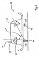
- the basic measuring arrangement shown in FIG. 2 on a ground contact element 40 of the soil compaction device 1 provides an angle measurement of an angle ⁇ by means of an angle sensor (not shown).
- the angle ⁇ spans between two planes, each intersecting the imbalance center and the longitudinal axis of an exciter shaft 41, 42.
- the rotational speed n of the two exciter shafts 41, 42 are respectively measured by means of a tachometer, also not shown.
- an acceleration sensor 43 measures the acceleration a that the ground contact element 40 performs by the vibrations transmitted thereto from the exciter shafts.
- the soil stiffness k B of the substrate is shown as a spring 44 and the damping c B of the substrate as a damping element 45. Both latter parameters are not measured directly, but calculated analytically and / or numerically by means of the aforementioned and / or other parameters from the measuring system 35.
Landscapes
- Engineering & Computer Science (AREA)
- General Engineering & Computer Science (AREA)
- Mechanical Engineering (AREA)
- Architecture (AREA)
- Civil Engineering (AREA)
- Structural Engineering (AREA)
- Investigation Of Foundation Soil And Reinforcement Of Foundation Soil By Compacting Or Drainage (AREA)
- Road Paving Machines (AREA)
- Fluid-Pressure Circuits (AREA)
Abstract
Description
Die Erfindung betrifft ein Bodenverdichtungsgerät, insbesondere eine Verdichtungsplatte, mit einem internen oder externen Antriebsaggregat, insbesondere einem Verbrennungsmotor, einer von diesem antreibbaren Hydraulikpumpe, einem Hydraulikmotor, der von der Hydraulikpumpe über eine Hauptleitung mit Hydraulikflüssigkeit versorgbar ist und mit dem ein Schwingungserreger antreibbar ist, mit dem das Bodenverdichtungsgerät in Schwingungen versetzbar ist.The invention relates to a soil compaction device, in particular a compression plate, with an internal or external drive unit, in particular an internal combustion engine, a hydraulic pump driven by this, a hydraulic motor, which is supplied from the hydraulic pump via a main line with hydraulic fluid and with which a vibration exciter is driven, with the soil compaction device is vibratable.
Die Leistung des Hydraulikmotors und des davon angetriebenen Schwingungserregers und damit die ausgeführten Schwingungen des Bodenverdichtungsgerätes bestimmen sich bekanntermaßen, wie beispielsweise bei den Bodenverdichtungsgeräten der Firma Ammann in Form von Vibrationswalzen, Stampfern, Anbauverdichtern und Walzenzügen, in erster Linie durch den von der Hydraulikpumpe umgesetzten Volumenstrom und damit durch die Drehzahl des diese antreibenden Verbrennungsmotors, solange keine Drehzahldifferenz zwischen Verbrennungsmotor und Hydraulikpumpe besteht. Eine Veränderung der Drehzahl des Verbrennungsmotors führt unmittelbar zu einer entsprechenden Änderung der Drehzahl des Hydraulikmotors. Die Schwingungen des Bodenverdichtungsgerätes können durch eine Drehzahlregulierung des Verbrennungsmotors unmittelbar gesteuert werden.The performance of the hydraulic motor and driven therefrom vibration exciter and thus the running oscillations of the soil compactor are known to be, for example, in the soil compaction equipment of Ammann in the form of vibratory rollers, rammers, mounted compressors and compactors, primarily by the volume flow converted by the hydraulic pump and thus by the speed of the driving this internal combustion engine, as long as there is no speed difference between the engine and hydraulic pump. A change in the rotational speed of the internal combustion engine leads directly to a corresponding change in the rotational speed of the hydraulic motor. The vibrations of the soil compacting device can be directly controlled by a speed control of the internal combustion engine.
Es ist bei Verdichtungsplatten lediglich bekannt, dass mehrere Betriebszustände, meist allerdings nur zwei, etwa ein Ruhezustand, bei dem der Erreger stillsteht, und ein erster Normalbetriebszustand, bei dem der Erreger mit maximaler Leistung angetrieben ist, eingenommen werden. Bei Vibrationswalzen ist es hingegen auch bekannt, eine hinsichtlich ihres Volumenstroms regelbare Hydraulikpumpe zu verwenden, um auch bei konstanter Drehzahl des Antriebsaggregats und der Pumpe die Verdichtungsleistung verändern zu können.It is only known in compression plates that several operating conditions, but usually only two, such as a resting state in which the pathogen is stationary, and a first normal operating state in which the exciter is driven at maximum power, are taken. In the case of vibratory rollers, on the other hand, it is also known to use a hydraulic pump which can be regulated in terms of its volumetric flow in order to be able to change the compression capacity even at a constant speed of the drive unit and of the pump.
Aus der
Des Weiteren ist aus der
Die Aufgabe der Erfindung ist es, ein Bodenverdichtungsgerät und ein Verfahren zum Betrieb des selben vorzuschlagen, welches es ermöglicht, auf einfache und zuverlässige Weise eine Mehrzahl von Betriebszuständen möglichst schnell und möglichst stufenlos (alternativ auch in hinreichend vielen kleinen Stufen) einzustellen. Eine Drehrichtungsumkehr beim Wechsel der Betriebszustände sollte auf jeden Fall vermieden werden.The object of the invention is to propose a soil compaction device and a method for operating the same, which makes it possible to set a plurality of operating states as quickly as possible and as continuously as possible (alternatively also in sufficiently many small steps) in a simple and reliable manner. A Direction of rotation reversal when changing the operating states should be avoided in any case.
Die erfindungsgemäße Aufgabe wird durch ein Stromregelventil, insbesondere ein Proportional-Stromregelventil gelöst, das in der Hauptleitung zwischen der Hydraulikpumpe und dem Hydraulikmotor angeordnet ist und mittels dessen der dem Hydraulikmotor zugeführte Volumenstrom der Hydraulikflüssigkeit unter Beibehaltung der jeweiligen Strömungsrichtung mengenmäßig veränderbar ist.The object of the invention is achieved by a flow control valve, in particular a proportional flow control valve, which is arranged in the main line between the hydraulic pump and the hydraulic motor and by means of which the hydraulic motor supplied volume flow of the hydraulic fluid while maintaining the respective flow direction is variable in volume.
Ebenfalls wird die erfindungsgemäße Aufgabe dadurch gelöst, dass ein Verfahren zur Erzeugung mehrerer Betriebszustände eines Bodenverdichtungsgeräts gemäß den Merkmalen des Oberbegriffs des Verfahrenshauptanspruchs vorgeschlagen wird, welches dadurch gekennzeichnet ist, dass mittels eines. Stromregelventils, insbesondere eines Proportional-Stromregelventils, der dem Hydraulikmotor zugeführte Volumenstrom der Hydraulikflüssigkeit unter Beibehaltung der jeweiligen Strömungsrichtung mengenmäßig verändert und dadurch die Drehzahl des Hydraulikmotors ebenfalls verändert wird und mehrere Betriebszustände des Bodenverdichtungsgerätes erreicht werden.Also, the object of the invention is achieved in that a method for generating a plurality of operating conditions of a soil compaction device according to the features of the preamble of the method main claim is proposed, which is characterized in that by means of a. Flow control valve, in particular a proportional flow control valve, the hydraulic motor supplied volume flow of the hydraulic fluid changed quantitatively while maintaining the respective flow direction and thereby the speed of the hydraulic motor is also changed and several operating conditions of the soil compaction device can be achieved.
Unter einem Stromregelventil soll in diesem Zusammenhang eine in der Hauptleitung angeordnete hydraulische Verstelleinrichtung verstanden werden, die den dem Hydraulikmotor zugeführten Volumenstrom unabhängig von dem von der Hydraulikpumpe abgegebenen Volumenstrom unter Beibehaltung der jeweiligen Strömungsrichtung mengenmäßig verändern kann. Für eine solche Aufgabenstellung sind Stromregelventile die üblichen Bauelemente. Dabei kann die Volumenstromveränderung sowohl bei nur einer Drehrichtung des Schwingungserregers als auch bei zwei entgegengesetzten Drehrichtungen wirksam sein, falls dies in Sonderfällen gewünscht ist.In this context, a flow control valve is to be understood as a hydraulic adjusting device arranged in the main line, which can quantitatively change the volume flow supplied to the hydraulic motor independently of the volumetric flow output by the hydraulic pump while maintaining the respective flow direction. For such a task flow control valves are the usual components. In this case, the change in volume flow can be effective both in only one direction of rotation of the vibration exciter and in two opposite directions of rotation, if this is desired in special cases.
Das Wesen der Erfindung ist somit in der hydraulischen Leistungsregelung zu sehen, von der bislang insbesondere bei Verdichtungsplatten keinerlei Gebrauch gemacht wurde. Gebräuchlich ist lediglich die Steuerung der Motordrehzahl oder eine Schlupfregelung zwischen Antriebsaggregat und Hydraulikpumpe, also eine mechanische Steuerung. In Bezug auf Verdichtungsplatten ist dabei jegliche hydraulische Leistungsregelung bislang nicht realisiert worden, so dass im Rahmen der Erfindung statt des Stromregelventils auch eine geregelte Pumpe oder ein geregelter Motor Verwendung finden können. In allen drei Fällen liegt eine hydraulische Beeinflussung der Drehzahl des Hydraulikmotors vor, um dessen Drehzahl, d.h. auch die Drehzahl des Schwingungserregers und damit die Verdichtungsleistung, zu ändern. Die mechanische Kopplung zwischen Antriebsaggregat und Hydraulikpumpe kann dabei ebenso starr sein wie die Kopplung zwischen Hydraulikmotor und Schwingungserreger.The essence of the invention is thus to be seen in the hydraulic power control, was previously made of the particular in compression plates no use. Common is only the control of the engine speed or a slip control between the drive unit and hydraulic pump, so a mechanical control. In terms of compression plates, any hydraulic power control has not been realized so far, so that in the context of the invention instead of the flow control valve and a regulated pump or a controlled motor can be used. In all three Cases is a hydraulic influence on the speed of the hydraulic motor in order to change the speed, ie, the speed of the vibration generator and thus the compaction performance. The mechanical coupling between the drive unit and the hydraulic pump can be just as rigid as the coupling between the hydraulic motor and the vibration exciter.
Bei den allgemein aus dem Stand der Technik bekannten Stromregelventilen kann durch Verstellen eines geeigneten hydraulischen Widerstandes gegen eine Feder der Strömungswiderstand entsprechend vergrößert oder verkleinert und dadurch der Volumenstrom geregelt werden.In the flow control valves generally known from the prior art, by adjusting a suitable hydraulic resistance against a spring, the flow resistance can be correspondingly increased or reduced, thereby controlling the volume flow.
Insbesondere bietet die Verwendung eines Proportional-Stromregelventils die Möglichkeit, den Volumenstrom proportional zu einer Stellgröße, etwa einem elektrischen Strom zu ändern.In particular, the use of a proportional flow control valve provides the ability to change the flow rate in proportion to a manipulated variable, such as an electrical current.
Eine Weiterbildung der Erfindung besteht darin, dass durch ein 3-Wege-Stromregelventil, der von der Hydraulikpumpe gelieferte Volumenstrom in einen dem Hydraulikmotor zugeführten ersten Teilvolumenstrom und einen dem Tank zugeführten zweiten Teilvolumenstrom aufteilbar ist.A further development of the invention consists in that, by means of a 3-way flow control valve, the volumetric flow delivered by the hydraulic pump can be divided into a first partial volumetric flow supplied to the hydraulic motor and a second partial volumetric flow supplied to the tank.
Der Vorteil bei der Verwendung eines 3-Wege-Stromregelventils besteht darin, dass die bei der Drosselung im Stromregelventil entstehende Wärme in den Tank abgeleitet weiden kann. Zudem ist bei einem 3-Wege-Stromregelventil der Druckabfall in dem dem Hydraulikmotor zugeleiteten Teilvolumenstrom (d.h. dem energetisch genutzten Volumenstrom) mit ca. 2 bar relativ gering. Bei einem 3-Wege-Stromregelventil muss im übrigen nur gegen den erforderlichen Lastdruck gearbeitet werden. Der Wirkungsgrad eines 3-Wege-Stromregelventils ist deswegen entsprechend hoch.The advantage of using a 3-way flow control valve is that the heat generated during throttling in the flow control valve can be drained into the tank. In addition, in a 3-way flow control valve, the pressure drop in the partial volume flow (i.e., the energetically used flow rate) supplied to the hydraulic motor is relatively small at about 2 bar. In the case of a 3-way flow control valve, moreover, it is only necessary to work against the required load pressure. The efficiency of a 3-way flow control valve is therefore correspondingly high.
Eine Weiterbildung der Erfindung besteht außerdem darin, dass das Stromregelventil, insbesondere das 3-Wege-Proportional-Stromregelventil, durch eine Regelmagnetvorrichtung geregelt ist. Durch die Änderung eines durch die Regelmagnetvorrichtung, etwa einen Proportionalmagneten, fließenden Stroms erfolgt unmittelbar eine Volumenstromänderung, die proportional zur Änderung des elektrischen Stromes ist:A further development of the invention also consists in that the flow control valve, in particular the 3-way proportional flow control valve, is regulated by a regulating magnet device. By changing a current flowing through the regulating magnet device, such as a proportional magnet, a volume flow change that is proportional to the change of the electric current takes place directly:
Die Erfindung kann ebenfalls dadurch weitergebildet werden, dass das Stromregelventil durch eine mechanische Regelvorrichtung, eine hydraulische Regelvorrichtung oder eine Kombination aus elektrischen, mechanischen, hydraulischen und/oder magnetischen Mitteln geregelt oder gesteuert ist.The invention can also be further developed in that the flow control valve is controlled or controlled by a mechanical control device, a hydraulic control device or a combination of electrical, mechanical, hydraulic and / or magnetic means.
Eine vorteilhafte Weiterbildung sieht außerdem vor, dass eine Steuer- oder Regelvorrichtung mittels eines von einem Messsystem gelieferten Steuerstroms oder einer Steuerspannung steuerbar oder regelbar ist, wobei das Messsystem die Verdichtung des Untergrundes, insbesondere unter dem Bodenverdichtungsgerät, misst.An advantageous development also provides that a control or regulating device can be controlled or regulated by means of a control current supplied by a measuring system or a control voltage, wherein the measuring system measures the compaction of the substrate, in particular under the soil compacting device.
Das Messsystem, welches die Schwingungen einer Bodenkontakteinheit des Bodenverdichtungsgerätes messen kann, insbesondere die Einwirkungsfrequenz sowie die Amplituden hierzu, liefert ein Maß für die Bodensteifigkeit (den Verdichtungsgrad) des Untergrundes und soll einen Steuerstrom ausgeben, der in die Regelmagnetvorrichtung eingespeist wird. Selbstverständlich ist völlig freigestellt, wie diese Steuergröße geartet ist; festgelegt soll nur sein, dass ein Ergebnis und/oder Zwischenergebnis der Messung des Messsystems zur Steuerstrombildung zu irgendeinem Zeitpunkt für eine wählbare Zeitspanne zur Volumenstromveränderung herangezogen wird.The measuring system, which can measure the vibrations of a ground contact unit of the soil compaction device, in particular the action frequency and the amplitudes thereto, provides a measure of the soil stiffness (the degree of compaction) of the substrate and should output a control current which is fed to the control magnet device. Of course, it is completely optional, how this tax amount is; is to be determined only that a result and / or intermediate result of the measurement of the measuring system for control current formation is used at any time for a selectable period of time for volume flow change.
Eine vorteilhafte Weiterbildung des Verfahrens sieht vor, dass der Hydraulikmotor durch entsprechende Anpassung des ihm zur Verfügung gestellten Volumenstroms in einem Normalbetriebszustand 100 % seiner Nennleistung, in einem Abregelbetriebszustand z.B. 80 % seiner Nennleistung, in einem Messbetriebszustand z.B. 20 % seiner Nennleistung und in einem Ruhebetriebszustand keine Leistung abgibt.An advantageous development of the method provides that the hydraulic motor, by appropriately adapting the volume flow provided to it in a normal operating state, obtains 100% of its nominal power, in a Abregelbetriebszustand e.g. 80% of its rated power, in a measuring mode, e.g. 20% of its rated output and no power in a quiescent operating state.
Der Abregelbetriebszustand ist vor allem dazu geeignet, bei schon erreichter maximaler bzw. gewünschter Bodensteifigkeit den Untergrund nicht wieder unbeabsichtigt - zumindest oberflächlich- zu lockern, sondern das Bodenverdichtungsgerät lediglich zu verschieben, d.h. dessen Ort zu ändern. In dem Abregelbetriebszustand ist zudem gewährleistet, dass es nicht zu einem "Springen" des Bodenverdichtungsgerätes, insbesondere des Bodenkontaktelementes, kommen kann. Zudem wird in diesem Betriebszustand das Bodenverdichtungsgerät vor Überlastung geschützt.The Abregelbetriebszustand is especially suitable for not already inadvertently - at least superficially - loosen at subsurface already reached maximum or desired soil stiffness, but the Bodenverdichtungsgerät only to move, ie to change its location. In the Abregelbetriebszustand is also ensured that it can not come to a "jumping" of the soil compaction device, in particular the ground contact element. In addition, the soil compaction device is protected from overloading in this operating condition.
Schließlich soll eine Weiterbildung des Verfahrens darin bestehen, dass innerhalb des Messbetriebszustands und/oder des Abregelbetriebszustands Schwingungen der Bodenverdichtungsvorrichtung ermittelt werden und daraus insbesondere eine Schwingungsform aufgenommen wird, aus der unter Einbeziehung von Maschinenparametern der Bodenverdichtungsvorrichtung und der zeitlichen Lage einer die Schwingung erzeugenden Bodenverdichtungskraft, die Bodensteifigkeit (Verdichtungsgrad) ermittelt und zur Bestimmung des Steuerstromes herangezogen wird.Finally, a further development of the method is that vibrations of the soil compacting device are determined within the measuring operating state and / or the Abregelbetriebszustingung and in particular a waveform is recorded from the incorporating machine parameters of the soil compacting device and the timing of the vibration generating soil compaction force, the Soil stiffness (degree of compaction) is determined and used to determine the control current.
Im Folgenden soll anhand von Ausführungsbeispielen das erfindungsgemäße Bodenverdichtungsgerät näher erläutert werden.The soil compacting device according to the invention will be explained in more detail below on the basis of exemplary embodiments.
Es zeigt
- Fig. 1
- einen Hydraulikplan eines erfindungsgemäßen Bodenverdichtungsgerätes mit Stromregelventil,
- Fig. 1a
- einen alternativen Hydraulikplan mit regelbarer Hydraulikpumpe,
- Fig. 1b
- einen weiteren alternativen Hydraulikplan mit regelbarem Hydraulikmotor,
- Fig. 2
- eine prinzipielle Ansicht einer Messanordnung an einem Bodenkontaktelement.
- Fig. 1
- a hydraulic plan of a soil compaction device according to the invention with flow control valve,
- Fig. 1a
- an alternative hydraulic plan with adjustable hydraulic pump,
- Fig. 1b
- another alternative hydraulic plan with adjustable hydraulic motor,
- Fig. 2
- a schematic view of a measuring arrangement on a ground contact element.
Das im Hydraulikplan der Fig.1 dargestellte Bodenverdichtungsgerät 1 in Form einer Verdichtungsplatte weist einen nicht gezeigten Verbrennungsmotor in Form eines Dieselmotors auf, der über eine ebenfalls nicht gezeigte starre Kupplung eine Hydraulikpumpe 2 antreibt. Die Hydraulikpumpe 2 föxdert Hydraulikflüssigkeit über eine Förderleitung 3 aus einem Tank 4. Die Hydraulikflüssigkeit wird dabei durch einen Saugfilter 5, der in der Förderleitung 3 angeordnet ist, von möglichen Verunreinigungen gereinigt.1 in the form of a compression plate has an internal combustion engine, not shown, in the form of a diesel engine, which drives a
Die Hydraulikflüssigkeit wird von der Hydraulikpumpe 2 über eine Hauptleitung 7 in einen Ventilblock 6 gepumpt. In dem Ventilblock 6 verzweigt sich die Hauptleitung 7 und führt zu einem Druckregelventil 8, einem Druckbegrenzungsventil 9 und einem Stromregelventil 10 in Form eines 3-Wege-Proportional-Stromregelventils. Von dem Stromregelventil 10 führt die Hauptleitung 7 in einem weiteren Abschnitt 7a zu einem Hydraulikmotor 23 und von dort über einen Rücklauffilter 23' in den Tank 4.The hydraulic fluid is pumped by the
Von dem Druckregelventil 8, welches den Druck auf 30 bar begrenzt, führt eine Hydraulikleitung 11 zu einer Verzweigung 12, von wo sie sich in eine Zuleitung 13 zu einem hydraulischen Verstellmechanismus 14 zur Verstellung eines hier nicht gezeigten Schwingungserregers mittels eines Stellzylinders 15 und in eine Rücklaufleitung 8' verzweigt, die mit einem Regeleingang 8" des Druckregelventils 8 verbunden ist. Ebenfalls vom Druckregelventil 8 geht eine Tankleitung 16 ab, die mit einer Tankleitung 17 des Druckbegrenzungsventils 9 und einer Tankleitung 18 des Stromregelventils 10 verbunden ist. Über die Tankleitungen 16, 17, 18 fließt die Hydraulikflüssigkeit aus dem Ventilblock 6 über eine gemeinsame weitere Tankleitung 19 zurück in den Tank 4. Das Druckbegrenzungsventil 9 ist für eine Druckbegrenzung auf 180 bar ausgelegt. An das Stromregelventil 10 ist eine magnetische Steuervorrichtung 33, z.B. in Form einer Spule mit Anker, angeschlossen, die mit dem hydraulischen Widerstandselement in dem Stromregelventil gekoppelt ist.From the
Wie in Fig. 1 gezeigt, wird der Steuerstrom Is für die Steuervorrichtung 33 des Stromregelventils 10 einem Messystem 35, insbesondere einem Mikroprozessor 36 entnommen, welches Geräteparameter (Drehzahlen von Erregerwellen 41, 42 siehe Fig. 2) und Schwingungsparameter einschließlich der Amplituden und Frequenzen der vom Bodenverdichtungsgerät 1 ausgeführten Schwingungen misst oder verwendet.As shown in FIG. 1, the control current I s for the
Auf einer Instrumententafel 37 des Bodenverdichtungsgerätes 1 werden die vom Messsystem 35 gemessenen Relativ- und Absolutwerte der Schwingungen ausgegeben, wobei auf einer Anzeige 37a ein Wert für den gemessenen absoluten Verdichtungsgrad und auf einer Anzeige 37r ein Wert für den relativen Verdichtungsgrad ausgegeben wird.On an
In das Messsystem 35 kann im übrigen noch mittels eines Vibrationsschalters 38 und eines Messschalters 39 eingegriffen werden. Der Vibrationsschalter 38 schaltet zwischen dem Ruhe und dem Normalbetriebszustand, wobei alternativ auch noch der Abregelzustand manuell schaltbar sein kann.Incidentally, it is also possible to intervene in the measuring system 35 by means of a vibration switch 38 and a measuring switch 39. The vibration switch 38 switches between the rest and the normal operating state, wherein alternatively also the Abregelzustand can be manually switched.
Ausgehend vom Normalbetriebszustand wird mittels des Messystems 35 ständig der relative Verdichtungsfortschritt einer während der Verdichtung gemessen und der Wert auf der Anzeige 37r angezeigt. Sobald ein Schwellenwert, der proportional zum Verdichtungsfortschritt sein kann, unterschritten wird, dh. sobald kein genügend großer Verdichtungsfortschritt mehr erreicht wird, regelt das Bodenverdichtungsgerät 1 sich mittels des Stromregelventils 10 automatisch in den Abregelbetriebszustand mit gegenüber dem Normalbetriebszustand geringerer abgegebener Leistung des Hydraulikmotors 23 herunter, wobei auch in diesem Zustand ständig eine Relativmessung vorgenommen wird. Falls wieder ein genügend großer Verdichtungsfortschritt, der einen weiteren Schwellenwert überschreitet, gemessen wird, schaltet das Bodenverdichtungsgerät 1 automatisch in den Normalbetriebszustand.Starting from the normal operating state, the relative compression progress of a during compaction is continuously measured by means of the measuring system 35 and the value displayed on the
Manuell oder automatisch sind somit die Betriebszustände in der Weise schaltbar, dass vom Messsystem ein entsprechender Steuerstrom Is zur Ansteuerung des Stromregelventils 10 ausgegeben wird. Dadurch wird schließlich, abhängig vom jeweiligen Volumenstrom, vom Hydraulikmotor in einem Normalbetriebszustand seine volle Nennleistung, in einem Abregelbetriebszustand ca. 80 % seiner Nennleistung, in einem Messbetriebszustand ca. 20 % seiner Nennleistung und in einem Ruhebetriebszustand schließlich keine Leistung abgegeben.Manually or automatically, the operating states are thus switchable in such a way that a corresponding control current I s for controlling the
Durch den Messschalter 39 kann zwischen einem Absolut- und einem ansonsten Relativmessprogramm des Mikroprozessors 36, das ständig im Hintergrund abläuft, gewechselt werden, wobei für die Absolutmessung vorzugsweise der Messbetriebszustand mit entsprechend niedriger Nennleistung des Hydraulikmotors geeignet ist. Beispielsweise können bei einem nicht weiter zu verdichtenden Boden, die absoluten Endwerte der Verdichtung, z.B. kombiniert mit entsprechenden GPS-Daten, vom Messsystem ausgegeben und optional gespeichert werden.By measuring switch 39 can be between an absolute and an otherwise relative measurement program of the
Die Fig. 1a zeigt einen alternativen Hydraulikplan, bei dem der Unterschied zu dem Hydraulikplan gemäß Fig. 1 darin besteht, dass anstelle des Stromregelventils 10 nunmehr die Hauptleitung 7 durchgängig von der Hydraulikpumpe 2 zu dem Hydraulikmotor 23 ohne Unterbrechung ist. Anstelle einer Hydraulikpumpe mit fester Förderrate ist gemäß Fig. 1a jedoch eine regelbare Hydraulikpumpe 2, d.h. eine solche mit veränderbarem geliefertem Volumenstrom vorhanden. Diese Hydraulikpumpe 2 wird über eine Steuervorrichtung 33 angesteuert, die mit der Verstelleinrichtung 33 gemäß Fig. 1 im Wesentlichen identisch sein kann. Wiederum erhält die Steuervorrichtung 33 ihre Steuersignale von dem Mikroprozessor 36. Die regelbare Hydraulikpumpe 2 ist über eine gestrichelt eingetragene Leckölleitung mit dem Tank verbunden.FIG. 1a shows an alternative hydraulic plan in which the difference to the hydraulic plan according to FIG. 1 is that instead of the
Fig. 1b zeigt einen weiteren alternativen Hydraulikplan, bei dem anstelle eines Stromregelventils 10 (Fig. 1) bzw. einer regelbaren Hydraulikpumpe 2 (Fig. 1a) ein regelbarer Hydraulikmotor 23 vorhanden ist. In Abhängigkeit von der Stellung einer Steuervorrichtung 33, wiederum angesteuert durch den Mikroprozessor 36, wird ein mehr oder weniger großer Volumenstrom drucklos in den Tank abgeleitet. Während somit im Falle der Fig. 1a die Hydraulikpumpe 2 aufgrund ihrer Regelbarkeit stets den aktuell vom Hydraulikmotor 23 benötigten Volumenstrom liefert, erhält letztere im Falle der Fig. 1b stets einen konstanten Volumenstrom, der in dem Hydraulikmotor 23 in einen effektiv genutzten Volumenstrom und einen drucklos in den Tank zurückströmenden Rücklaufvolumenstrom aufgeteilt wird.FIG. 1b shows a further alternative hydraulic plan in which, instead of a flow control valve 10 (FIG. 1) or a controllable hydraulic pump 2 (FIG. 1a), a controllable
Die in Fig. 2 gezeigte prinzipielle Messanordnung an einem Bodenkontaktelement 40 des Bodenverdichtungsgeräts 1 sieht eine Winkelmessung eines Winkels ϕ mittels eines nicht gezeigten Winkelsensors vor. Der Winkel ϕ spannt sich zwischen zwei Ebenen, die jeweils den Unwuchtschwerpunkt und die Längsachse einer Erregerwelle 41, 42 schneiden. Zudem werden die Drehzahl n der beiden Erregerwellen 41, 42 jeweils mittels eines ebenfalls nicht gezeigten Drehzahlmessers gemessen. Ein Beschleunigungssensor 43 misst schließlich die Beschleunigung a, die das Bodenkontaktelement 40 durch die von den Erregerwellen auf es übertragenen Schwingungen durchführt. Lediglich zur Verdeutlichung ist die Bodensteifigkeit kB des Untergrundes als Feder 44 und die Dämpfung cB des Untergrundes als Dämpfungselement 45 dargestellt. Beide letztgenannten Parameter werden nicht direkt gemessen, sondern analytisch und/oder numerisch mittels der zuvor genannten und/oder anderer Parameter vom Messsystem 35 berechnet.The basic measuring arrangement shown in FIG. 2 on a ground contact element 40 of the soil compaction device 1 provides an angle measurement of an angle φ by means of an angle sensor (not shown). The angle φ spans between two planes, each intersecting the imbalance center and the longitudinal axis of an
- 11
- BodenverdichtungsgerätSoil Compactor
- 22
- Hydraulikpumpehydraulic pump
- 33
- Förderleitungdelivery line
- 44
- Tanktank
- 55
- SaugfilterSuction
- 66
- Ventilblockmanifold
- 77
- Hauptleitungmain
- 7a7a
- Abschnitt der HauptleitungSection of the main line
- 88th
- DruckregelventilPressure control valve
- 8'8th'
- RücklaufleitungReturn line
- 99
- DruckbegrenzungsventilPressure relief valve
- 1010
- StromregelventilFlow control valve
- 1111
- Hydraulikleitunghydraulic line
- 1212
- Verzweigungbranch
- 1313
- Zuleitungsupply
- 1414
- Verstellmechanismusadjustment
- 1515
- Stellzylinderactuating cylinder
- 1616
- Tankleitungtank line
- 1717
- Tankleitungtank line
- 1818
- Tankleitungtank line
- 1919
- Tankleitungtank line
- 2323
- Hydraulikmotorhydraulic motor
- 3333
- Steuervorrichtungcontrol device
- 3636
- Mikroprozessormicroprocessor
- 3737
- Instrumententafeldashboard
- 37a37a
- Anzeige füt absolute MesswerteDisplay for absolute measured values
- 37r37r
- Anzeige füt relative MesswerteDisplay for relative readings
- 3838
- Vibrationsschaltervibration switch
- 3939
- Messschaltermeasurement switch
- 4040
- Schwingungserregervibration exciter
- 4141
- Erregerwelleexciter shaft
- 4242
- ErregertwelleErregertwelle
- 4343
- Beschleunigungssensoraccelerometer
- 4444
- Federfeather
- 4545
- Dämpfungselementdamping element
- IV I V
- VerstellstromVerstellstrom
- IR I R
- Regelstromcontrol current
- IJ I J
- Stromelectricity
- nn
- Drehzahlrotation speed
- kB k B
- Bodensteifigkeitsoil stiffness
- cB c B
- Dämpfungdamping
- aa
- Beschleunigungacceleration
- ϕφ
- Winkelangle
Claims (10)
Applications Claiming Priority (1)
| Application Number | Priority Date | Filing Date | Title |
|---|---|---|---|
| DE200510022627 DE102005022627A1 (en) | 2005-05-11 | 2005-05-11 | Soil Compactor |
Publications (2)
| Publication Number | Publication Date |
|---|---|
| EP1722036A2 true EP1722036A2 (en) | 2006-11-15 |
| EP1722036A3 EP1722036A3 (en) | 2008-03-05 |
Family
ID=36844877
Family Applications (1)
| Application Number | Title | Priority Date | Filing Date |
|---|---|---|---|
| EP06009636A Withdrawn EP1722036A3 (en) | 2005-05-11 | 2006-05-10 | Ground compacting machine |
Country Status (2)
| Country | Link |
|---|---|
| EP (1) | EP1722036A3 (en) |
| DE (1) | DE102005022627A1 (en) |
Cited By (7)
| Publication number | Priority date | Publication date | Assignee | Title |
|---|---|---|---|---|
| EP2085149A1 (en) | 2008-01-29 | 2009-08-05 | ABI Anlagentechnik-Baumaschinen-Industriebedarf Maschinenfabrik und Vertriebsgesellschaft mbH | Vibrator for a vibratory pile driver |
| CN101864722A (en) * | 2010-06-21 | 2010-10-20 | 厦工(三明)重型机器有限公司 | Vibratory roller and stable vibration start and vibration stop method adopted by same |
| EP1980671A3 (en) * | 2007-04-12 | 2012-06-27 | Ammann Verdichtung GmbH | Soil compacting device in form of a vibration plate |
| DE102011113485A1 (en) | 2011-09-15 | 2013-03-21 | Bomag Gmbh | Method for driving a drive train of a vehicle and device for carrying out the method |
| GB2498369A (en) * | 2012-01-12 | 2013-07-17 | Balfour Beatty Plc | Hydraulic control unit with graduated control of flow-rate |
| CN112482143A (en) * | 2020-10-21 | 2021-03-12 | 陈进军 | Device capable of adjusting vibration frequency for tamping concrete roadbed |
| DE102022209497A1 (en) | 2022-09-12 | 2024-03-14 | Robert Bosch Gesellschaft mit beschränkter Haftung | Method for controlling a hydrostatic drive |
Families Citing this family (3)
| Publication number | Priority date | Publication date | Assignee | Title |
|---|---|---|---|---|
| DE102007018743A1 (en) * | 2007-04-22 | 2008-10-23 | Bomag Gmbh | Method and system for controlling compaction machines |
| DE102009018490B4 (en) * | 2009-04-18 | 2015-05-28 | Mts Maschinentechnik Schrode Ag | Cultivation compressor, which can be coupled to an excavator, with an unbalance generator |
| DE102022117908A1 (en) | 2022-07-18 | 2024-01-18 | Mts Schrode Ag | Attachment compactor |
Citations (5)
| Publication number | Priority date | Publication date | Assignee | Title |
|---|---|---|---|---|
| US3670631A (en) * | 1970-12-28 | 1972-06-20 | Clark Equipment Co | Rotating vibrator |
| US3867073A (en) * | 1972-09-20 | 1975-02-18 | Raygo Inc | Control for fluid motor |
| US4348901A (en) * | 1979-10-19 | 1982-09-14 | Koehring Gmbh-Bomag Division | Apparatus for monitoring the degree of compaction |
| DE4031476A1 (en) * | 1989-04-14 | 1992-04-09 | Kracht Gmbh | Hydraulic control circuit for synchronising two hydromachines - has by=pass valves in parallel with machines, enables machine of equal displacement to be used |
| WO2001081680A1 (en) * | 2000-04-20 | 2001-11-01 | Wacker-Werke Gmbh & Co. Kg | Oscillation detecting device for compacting soil |
Family Cites Families (4)
| Publication number | Priority date | Publication date | Assignee | Title |
|---|---|---|---|---|
| DE4211284C1 (en) * | 1992-04-03 | 1993-09-30 | Delmag Maschinenfabrik | Electronically controlled ground compactor - uses displacement of steering mass in axial direction of vibrator imbalance weights |
| DE4343865A1 (en) * | 1993-12-22 | 1995-07-13 | Ammann Duomat Verdichtung | Ground compacting machine with vibration plate |
| DE20013987U1 (en) * | 2000-08-14 | 2000-11-23 | Vibromax Bodenverdichtungsmaschinen GmbH, 06466 Gatersleben | Adjustment device for a vibrator |
| DE10356319A1 (en) * | 2003-11-28 | 2005-06-30 | ICE International Construction Equipment BV | Hydraulic vibrator with independently operated pump for lubrication and cooling circuit for shaft bearings operated ahead of main hydraulic motor |
-
2005
- 2005-05-11 DE DE200510022627 patent/DE102005022627A1/en not_active Withdrawn
-
2006
- 2006-05-10 EP EP06009636A patent/EP1722036A3/en not_active Withdrawn
Patent Citations (5)
| Publication number | Priority date | Publication date | Assignee | Title |
|---|---|---|---|---|
| US3670631A (en) * | 1970-12-28 | 1972-06-20 | Clark Equipment Co | Rotating vibrator |
| US3867073A (en) * | 1972-09-20 | 1975-02-18 | Raygo Inc | Control for fluid motor |
| US4348901A (en) * | 1979-10-19 | 1982-09-14 | Koehring Gmbh-Bomag Division | Apparatus for monitoring the degree of compaction |
| DE4031476A1 (en) * | 1989-04-14 | 1992-04-09 | Kracht Gmbh | Hydraulic control circuit for synchronising two hydromachines - has by=pass valves in parallel with machines, enables machine of equal displacement to be used |
| WO2001081680A1 (en) * | 2000-04-20 | 2001-11-01 | Wacker-Werke Gmbh & Co. Kg | Oscillation detecting device for compacting soil |
Cited By (9)
| Publication number | Priority date | Publication date | Assignee | Title |
|---|---|---|---|---|
| EP1980671A3 (en) * | 2007-04-12 | 2012-06-27 | Ammann Verdichtung GmbH | Soil compacting device in form of a vibration plate |
| EP2085149A1 (en) | 2008-01-29 | 2009-08-05 | ABI Anlagentechnik-Baumaschinen-Industriebedarf Maschinenfabrik und Vertriebsgesellschaft mbH | Vibrator for a vibratory pile driver |
| CN101864722A (en) * | 2010-06-21 | 2010-10-20 | 厦工(三明)重型机器有限公司 | Vibratory roller and stable vibration start and vibration stop method adopted by same |
| DE102011113485A1 (en) | 2011-09-15 | 2013-03-21 | Bomag Gmbh | Method for driving a drive train of a vehicle and device for carrying out the method |
| WO2013037500A1 (en) | 2011-09-15 | 2013-03-21 | Bomag Gmbh | Method for driving a drive train of a vehicle and apparatus for carrying out the method |
| US9638112B2 (en) | 2011-09-15 | 2017-05-02 | Bomag Gmbh | Method of controlling a power train of a vehicle and device for carrying out said method |
| GB2498369A (en) * | 2012-01-12 | 2013-07-17 | Balfour Beatty Plc | Hydraulic control unit with graduated control of flow-rate |
| CN112482143A (en) * | 2020-10-21 | 2021-03-12 | 陈进军 | Device capable of adjusting vibration frequency for tamping concrete roadbed |
| DE102022209497A1 (en) | 2022-09-12 | 2024-03-14 | Robert Bosch Gesellschaft mit beschränkter Haftung | Method for controlling a hydrostatic drive |
Also Published As
| Publication number | Publication date |
|---|---|
| EP1722036A3 (en) | 2008-03-05 |
| DE102005022627A1 (en) | 2006-11-16 |
Similar Documents
| Publication | Publication Date | Title |
|---|---|---|
| EP1722036A2 (en) | Ground compacting machine | |
| EP2770108B1 (en) | Tamping unit for a rail tamping machine | |
| EP2085149B2 (en) | Vibrator for a vibratory pile driver | |
| DE10212389B4 (en) | Speed control system for a compaction work machine and method of control | |
| EP1893819B1 (en) | Vibrating plate with individually adjustable vibration generators | |
| EP2557233B1 (en) | Tool with hydraulic drive for civil engineering work | |
| DE102008021670A1 (en) | Surface soil compactor and method of operating a surface soil compactor | |
| DE10235980B4 (en) | Variable vibration mechanism | |
| EP2984241B1 (en) | Vibrating driving arrangement, and method for operating the vibrating driving arrangement | |
| EP2627826A1 (en) | Method for determining the stiffness and/or damping of a body | |
| DE112012002670T5 (en) | Vibration frequency selection system | |
| EP0135479A1 (en) | Device for driving and extracting | |
| WO2018095558A1 (en) | Tamping unit for tamping sleepers of a track | |
| DE10046336B4 (en) | Soil compacting device with vibration exciter and method for controlling the vibration exciter | |
| DE19543910A1 (en) | Adjustment device for an unbalance directional oscillator with adjustable centrifugal moment | |
| EP2242590B1 (en) | Unbalance exciter with one or more rotatable unbalances | |
| EP2260210B1 (en) | Controller and the use thereof | |
| DE102010015950A1 (en) | Hand shaker for compacting materials in road, track and earthworks | |
| EP1534439B1 (en) | Vibration exciter for soil compacting devices | |
| WO2009138491A1 (en) | Shaking device | |
| EP1383616B1 (en) | Controller for an unbalanced mass adjusting unit of a soil compacting device | |
| DE102021200285A1 (en) | Compaction vehicle in which a travel drive and a vibration unit are supplied with pressurized fluid from a common supply point | |
| EP2266713B1 (en) | Oscillation exciter | |
| DE202007019293U1 (en) | Vibration generator for soil compacting devices | |
| WO2005056201A1 (en) | Piling vibrator for material that is to be rammed |
Legal Events
| Date | Code | Title | Description |
|---|---|---|---|
| PUAI | Public reference made under article 153(3) epc to a published international application that has entered the european phase |
Free format text: ORIGINAL CODE: 0009012 |
|
| AK | Designated contracting states |
Kind code of ref document: A2 Designated state(s): AT BE BG CH CY CZ DE DK EE ES FI FR GB GR HU IE IS IT LI LT LU LV MC NL PL PT RO SE SI SK TR |
|
| AX | Request for extension of the european patent |
Extension state: AL BA HR MK YU |
|
| PUAL | Search report despatched |
Free format text: ORIGINAL CODE: 0009013 |
|
| AK | Designated contracting states |
Kind code of ref document: A3 Designated state(s): AT BE BG CH CY CZ DE DK EE ES FI FR GB GR HU IE IS IT LI LT LU LV MC NL PL PT RO SE SI SK TR |
|
| AX | Request for extension of the european patent |
Extension state: AL BA HR MK YU |
|
| 17P | Request for examination filed |
Effective date: 20080610 |
|
| 17Q | First examination report despatched |
Effective date: 20080820 |
|
| AKX | Designation fees paid |
Designated state(s): AT BE BG CH CY CZ DE DK EE ES FI FR GB GR HU IE IS IT LI LT LU LV MC NL PL PT RO SE SI SK TR |
|
| STAA | Information on the status of an ep patent application or granted ep patent |
Free format text: STATUS: THE APPLICATION HAS BEEN WITHDRAWN |
|
| 18W | Application withdrawn |
Effective date: 20111124 |