EP2085149A1 - Vibrator for a vibratory pile driver - Google Patents
Vibrator for a vibratory pile driver Download PDFInfo
- Publication number
- EP2085149A1 EP2085149A1 EP08001601A EP08001601A EP2085149A1 EP 2085149 A1 EP2085149 A1 EP 2085149A1 EP 08001601 A EP08001601 A EP 08001601A EP 08001601 A EP08001601 A EP 08001601A EP 2085149 A1 EP2085149 A1 EP 2085149A1
- Authority
- EP
- European Patent Office
- Prior art keywords
- vibration generator
- sensor
- detecting
- generator according
- acceleration
- Prior art date
- Legal status (The legal status is an assumption and is not a legal conclusion. Google has not performed a legal analysis and makes no representation as to the accuracy of the status listed.)
- Granted
Links
- 230000001133 acceleration Effects 0.000 claims description 20
- 230000035515 penetration Effects 0.000 claims description 12
- 238000011156 evaluation Methods 0.000 claims description 9
- 238000006073 displacement reaction Methods 0.000 claims description 8
- 239000000463 material Substances 0.000 claims description 7
- 239000002689 soil Substances 0.000 claims description 7
- 230000001276 controlling effect Effects 0.000 claims description 4
- 230000001105 regulatory effect Effects 0.000 claims description 3
- 230000006870 function Effects 0.000 abstract description 4
- 230000003068 static effect Effects 0.000 description 10
- 230000001939 inductive effect Effects 0.000 description 5
- 238000011161 development Methods 0.000 description 4
- 230000018109 developmental process Effects 0.000 description 4
- 238000010521 absorption reaction Methods 0.000 description 3
- 239000012530 fluid Substances 0.000 description 3
- 238000012512 characterization method Methods 0.000 description 2
- 230000007423 decrease Effects 0.000 description 2
- 230000001419 dependent effect Effects 0.000 description 2
- 230000006978 adaptation Effects 0.000 description 1
- 238000010276 construction Methods 0.000 description 1
- 238000000151 deposition Methods 0.000 description 1
- 238000001514 detection method Methods 0.000 description 1
- 238000009434 installation Methods 0.000 description 1
- 239000007788 liquid Substances 0.000 description 1
- 238000005259 measurement Methods 0.000 description 1
- 230000003287 optical effect Effects 0.000 description 1
- 230000010355 oscillation Effects 0.000 description 1
- 230000000149 penetrating effect Effects 0.000 description 1
- 238000012545 processing Methods 0.000 description 1
- 238000012552 review Methods 0.000 description 1
- 230000000007 visual effect Effects 0.000 description 1
Images
Classifications
-
- B—PERFORMING OPERATIONS; TRANSPORTING
- B06—GENERATING OR TRANSMITTING MECHANICAL VIBRATIONS IN GENERAL
- B06B—METHODS OR APPARATUS FOR GENERATING OR TRANSMITTING MECHANICAL VIBRATIONS OF INFRASONIC, SONIC, OR ULTRASONIC FREQUENCY, e.g. FOR PERFORMING MECHANICAL WORK IN GENERAL
- B06B1/00—Methods or apparatus for generating mechanical vibrations of infrasonic, sonic, or ultrasonic frequency
- B06B1/10—Methods or apparatus for generating mechanical vibrations of infrasonic, sonic, or ultrasonic frequency making use of mechanical energy
- B06B1/16—Methods or apparatus for generating mechanical vibrations of infrasonic, sonic, or ultrasonic frequency making use of mechanical energy operating with systems involving rotary unbalanced masses
- B06B1/161—Adjustable systems, i.e. where amplitude or direction of frequency of vibration can be varied
- B06B1/166—Where the phase-angle of masses mounted on counter-rotating shafts can be varied, e.g. variation of the vibration phase
-
- E—FIXED CONSTRUCTIONS
- E02—HYDRAULIC ENGINEERING; FOUNDATIONS; SOIL SHIFTING
- E02D—FOUNDATIONS; EXCAVATIONS; EMBANKMENTS; UNDERGROUND OR UNDERWATER STRUCTURES
- E02D7/00—Methods or apparatus for placing sheet pile bulkheads, piles, mouldpipes, or other moulds
- E02D7/18—Placing by vibrating
Abstract
Description
Die Erfindung betrifft einen Schwingungserzeuger für ein Vibrationsrammgerät nach dem Oberbegriff des Patentanspruchs 1. Die Erfindung betrifft weiterhin ein Vibrationsrammgerät nach dem Patentanspruch 9.The invention relates to a vibration generator for a vibratory pile driver according to the preamble of claim 1. The invention further relates to a vibratory pile driver according to
Im Bauwesen werden Schwingungserzeuger verwendet, um Objekte, wie beispielsweise Profile, in den Boden einzubringen oder aus dem Boden zu ziehen oder auch um Bodenmaterial zu verdichten. Der Boden wird durch Vibration angeregt und erreicht so einen "pseudoflüssigen" Zustand. Durch statische Auflast kann das Rammgut dann in den Baugrund gedrückt werden. Die Vibration ist gekennzeichnet durch eine lineare Bewegung und wird durch paarweise gegenläufig rotierende Unwuchten innerhalb eines Vibratorgetriebes generiert. Schwingungserzeuger werden charakterisiert durch die rotierende Unwucht und die maximale Drehzahl.In construction, vibrators are used to bring objects such as profiles into the ground or to pull them out of the ground or to compact soil material. The soil is stimulated by vibration and thus reaches a "pseudo-liquid" state. By static load the pile can then be pressed into the ground. The vibration is characterized by a linear movement and is generated by pairwise counter-rotating imbalances within a Vibratorgetriebes. Vibration generators are characterized by the rotating unbalance and the maximum speed.
Die Schwingungserzeuger sind linear wirkende Schwingungserreger, deren Fliehkraft durch rotierende Unwuchten generiert wird. Diese Schwingungserreger bewegen sich mit veränderlicher Geschwindigkeit. Die Größe der Unwucht wird auch als "statisches Moment" bezeichnet. Der Verlauf der Geschwindigkeit des linearen Schwingungserregers entspricht einer periodisch wiederkehrenden Funktion, beispielsweise einer Sinusfunktion, sie kann aber auch andere Formen einnehmen.The vibration generators are linear vibration exciters whose centrifugal force is generated by rotating imbalances. These vibration exciters move at a variable speed. The size of the imbalance is also called "static moment". The course of the velocity of the linear vibration exciter corresponds to a periodically recurring function, for example a sine function, but it can also take other forms.
Schwingungserzeuger werden mit hydraulischen Antrieben betrieben, welche die Wellen, auf denen die Unwuchten angeordnet sind, in Rotation versetzen. Derartige hydraulische Antriebe weisen eine Leistungskurve auf, welche abhängig ist von der Betriebsdrehzahl bzw. vom Betriebsdruck. Bei gleicher Antriebsleistung ist durch eine niedrigere Drehzahl ein höheres statisches Moment erzielbar, wodurch gleichzeitig eine höhere Bodenschwingung bewirkt ist. Im Innenstadtbereich sind Bodenschwingungen zu vermeiden. Diese können durch einen Betrieb mit höherer Drehzahl reduziert werden, wodurch jedoch gleichzeitig das statische Moment verringert wird. Diese Maßnahmen erweisen sich als problematisch, da die erforderliche Antriebsleistung und das Drehmoment drehzahlabhängig sind. Wird der optimale Betriebsdrehzahlbereich des hydraulischen Antriebs bzw. Motors verlassen, so resultiert hieraus ein Leistungsabfall. Ebenso verringert sich das erforderliche Drehmoment am Motor bei wachsender Rammgutmasse. Dementsprechend verringert sich das Druckgefälle am Motor und die angebotene Antriebsleistung kann nur noch teilweise genutzt werden.Vibration generators are operated by hydraulic drives, which set the waves on which the imbalances are arranged in rotation. Such hydraulic drives have a power curve, which is dependent on the operating speed and the operating pressure. With the same drive power is achieved by a lower speed, a higher static torque, which at the same time a higher ground vibration is effected. In the inner city area floor vibrations are to be avoided. These can be reduced by operating at a higher speed, but at the same time reducing the static torque. These measures prove to be problematic because the required drive power and torque are speed dependent. If the optimum operating speed range of the hydraulic drive or motor is left, this results in a power loss. Likewise, the torque required on the engine decreases as the pile mass increases. Accordingly, the pressure gradient decreases on the engine and the offered drive power can only be partially used.
Hier will die Erfindung Abhilfe schaffen. Der Erfindung liegt die Aufgabe zu Grunde, einen Schwingungserzeuger zu schaffen, der einen Betrieb in unterschiedlichen Drehzahlbereichen ohne Leistungsabfall ermöglicht. Gemäß der Erfindung wird diese Aufgabe durch die Merkmale des kennzeichnenden Teils des Patentanspruchs 1 gelöst.The invention aims to remedy this situation. The invention is based on the object to provide a vibration generator that allows operation in different speed ranges without power loss. According to the invention, this object is solved by the features of the characterizing part of patent claim 1.
Mit der Erfindung ist ein Schwingungserreger geschaffen, der einen Betrieb in unterschiedlichen Drehzahlbereichen ohne Leistungsabfall ermöglicht. Durch den Einsatz eines hydraulischen Antriebs mit veränderbaren Schluckvolumen ist eine Anpassung der Leistungskurve auf den jeweils erforderlichen Drehzahlbereich ermöglicht. Einem Leistungsabfall des Antriebs ist hierdurch entgegengewirkt.With the invention, a vibration generator is provided which allows operation in different speed ranges without power loss. By the Use of a hydraulic drive with variable displacement makes it possible to adapt the power curve to the required speed range. A power loss of the drive is counteracted by this.
Unter Schluckvolumen wird bei Hydraulikmotoren bzw. -antrieben jene Menge an Hydraulikflüssigkeit verstanden, die der Hydraulikantrieb pro Umdrehung verbraucht. Die von einem Hydraulikantrieb abgegebene Leistung ist direkt proportional dem Schluckvolumen, der Drehzahl und dem Druckgefälle. Das Produkt aus Schluckvolumen und Drehzahl ergibt den Volumenstrom. Das Druckgefälle ist der Unterschied zwischen Druck der zulaufenden Hydraulikflüssigkeit (das ist in der Regel der Pumpendruck) und dem Druck der ablaufenden Hydraulikflüssigkeit (das ist in der Regel der Tankdruck).In the case of hydraulic motors or drives, the term "displacement volume" refers to the amount of hydraulic fluid consumed by the hydraulic drive per revolution. The power delivered by a hydraulic drive is directly proportional to the displacement, the speed and the pressure gradient. The product of the displacement and the speed results in the volume flow. The pressure gradient is the difference between the pressure of the incoming hydraulic fluid (which is usually the pump pressure) and the pressure of the hydraulic fluid (which is usually the tank pressure).
In Weiterbildung der Erfindung ist ein Steuermodul vorgesehen, über welches das Schluckvolumen in Abhängigkeit von Betriebsdruck oder Drehzahl einstellbar ist. Hierdurch ist eine kontinuierliche Anpassung der Leistungskurve des hydraulischen Antriebs ermöglicht, wodurch der Schwingungserzeuger die angebotene Leistung optimal nutzt.In a further development of the invention, a control module is provided, via which the absorption volume can be set as a function of operating pressure or rotational speed. This allows a continuous adjustment of the power curve of the hydraulic drive, whereby the vibrator optimally uses the offered power.
In Ausgestaltung der Erfindung ist ein Grenzbetriebsdruck oder eine Grenzdrehzahl einstellbar. Hierdurch ist ein definierter Betriebszustand einstellbar, bei dem eine Veränderung des Schluckvolumens initiiert werden soll.In an embodiment of the invention, a limit operating pressure or a limit speed is adjustable. This makes it possible to set a defined operating state in which a change in the absorption volume is to be initiated.
In Ausgestaltung der Erfindung ist ein Steuer- und Regelkreis vorgesehen, der eine Speichereinheit zur Hinterlegung von Bodenbeschaffenheits- oder Aufgabenspezifischen Vorgabe- Datensätzen mit definierten Betriebskenngrößen, umfasst, aus der ein jeweils erforderlicher Datensatz auswählbar ist, Sensoren zur kontinuierlichen Erfassung der definierten Betriebskenngrößen, eine Auswerteeinheit zum Vergleich der ermittelten Betriebskenngrüßen mit den Betriebskenngrößen des ausgewählten Vorgabe-Datensatzes, eine mit der Auswerteeinheit gekoppelte Regelvorrichtung zur Regelung des Schwingungserzeugers, sowie eine mit der Regelvorrichtung gekoppelte Steuervorrichtung zur Ansteuerung der Mittel zur Verstellung der relativen Drehposition der Unwuchtmassen zueinander. Hierdurch ist die Bereitstellung und Auswahl von in der Praxis erworbenen Erfahrungswerten in Art eines Expertensystems ermöglicht. In Abhängigkeit von der Aufgabenstellung kann so eine einfache Einstellung des Schwingungserzeugers durch Auswahl eines je nach Aufgabe zu wählenden Betriebsdatensatzes erfolgen.In an embodiment of the invention, a control and regulating circuit is provided, which comprises a storage unit for depositing soil condition or task-specific default data sets with defined operating characteristics, from which a respective required record is selectable, sensors for continuously recording the defined operating characteristics, an evaluation unit for comparing the determined operating characteristics with the operating characteristics of the selected default data set, a control device coupled to the evaluation unit for controlling the vibration generator, and a control device coupled to the control device for controlling the means for Adjustment of the relative rotational position of the imbalance masses to each other. This makes it possible to provide and select empirical values acquired in practice in the manner of an expert system. Depending on the task, a simple adjustment of the vibration generator can be made by selecting an operating data set to be selected according to the task.
Vorteilhaft ist das Steuermodul zur Einstellung des Schluckvolumens in dem Antrieb integriert. Alternativ kann das Steuermodul in dem Steuer- und Regelkreis integriert sein.Advantageously, the control module for adjusting the absorption volume is integrated in the drive. Alternatively, the control module can be integrated in the control and regulating circuit.
In Weiterbildung der Erfindung sind Sensoren zur Erfassung der Frequenz, der statischen Auflast sowie der relativen Position der Unwuchtmassen zueinander angeordnet. Bevorzugt umfassen die Sensoren wenigstens einen induktiven Sensor und/ oder einen Drehgeber. Derartige Sensoren haben sich als langlebig und robust erwiesen. Vorteilhaft ist ein Sensor zur Erfassung der Beschleunigung der rotierenden Wellen angeordnet. Ergänzend kann ein Sensor zur Erfassung der Amplitude der Schwingungen des Schwingungserzeugers angeordnet sein.In a further development of the invention sensors for detecting the frequency, the static load and the relative position of the imbalance masses are arranged to each other. Preferably, the sensors comprise at least one inductive sensor and / or a rotary encoder. Such sensors have proven to be durable and robust. Advantageously, a sensor for detecting the acceleration of the rotating shafts is arranged. In addition, a sensor for detecting the amplitude of the oscillations of the vibration generator can be arranged.
In Ausgestaltung der Erfindung ist eine Vorrichtung zur automatischen Auswahl eines Vorgabe-Datensatzes auf Grundlage der ermittelten Beschleunigungswerte vorgesehen. Hierdurch ist eine Programmautomatik realisierbar, durch die in Abhängigkeit von der aufgabenspezifischen Betriebssituation die automatische Auswahl der effizientesten Vorgabegrößen erfolgt, ohne dass ein Eingriff des Bedieners erforderlich ist. Alternativ kann auch eine Halbautomatik realisiert werden, bei der dem Bediener ein Betriebskenngrößendatensatz vorgeschlagen wird, welcher durch den Bediener bestätigt oder verändert werden kann.In an embodiment of the invention, a device for the automatic selection of a default data set on the basis of the determined acceleration values is provided. In this way, a program automation can be implemented, by means of which, depending on the task-specific operating situation, the automatic selection of the most efficient predefined variables takes place, without intervention by the operator being necessary. Alternatively, a semi-automatic can be realized in which the operator an operating characteristic data record is proposed, which can be confirmed or changed by the operator.
Vorteilhaft weist die Auswerteeinheit eine speicherprogrammierbare Steuerung (SPS) auf. Hierdurch ist eine flexible Steuerung des Schwingungserzeugers ermöglicht.The evaluation unit advantageously has a programmable logic controller (PLC). This allows flexible control of the vibration generator.
In Weiterbildung der Erfindung ist eine akustische und/oder optische Warneinrichtung zur Alarmierung von Fehleingaben vorgesehen, die mit der Auswerteeinheit verbunden ist. Hierdurch kann der Bediener auf eine erforderliche Anpassung bzw. Änderung der aktuellen Betriebskenngrößen hingewiesen werden.In a development of the invention, an acoustic and / or visual warning device is provided for alerting incorrect inputs, which is connected to the evaluation unit. In this way, the operator can be notified of a required adaptation or change of the current operating parameters.
Der Erfindung liegt weiterhin die Aufgabe zu Grunde, ein Vibrationsrammgerät zu schaffen, das einen Betrieb in unterschiedlichen Drehzahlbereichen ohne Leistungsabfall ermöglicht. Gemäß der Erfindung wird diese Aufgabe durch die Merkmale des Patentanspruchs 9 gelöst.The invention is further based on the object to provide a Vibratoryrammgerät that allows operation in different speed ranges without power loss. According to the invention, this object is solved by the features of
Mit der Erfindung ist ein Vibrationsrammgerät geschaffen, das einen Betrieb in unterschiedlichen Drehzahlbereichen ohne Leistungsabfall ermöglicht.With the invention, a vibration racking device is provided which allows operation in different speed ranges without power loss.
In Ausgestaltung der Erfindung ist ein Sensor zur Erfassung der auf das Rammgut einwirkenden Kräfte angeordnet. Durch die Ermittlung dieser Größe ist eine Charakterisierung der Bodenbeschaffenheit ermöglicht. Diese Charakterisierung kann durch die bevorzugte Anordnung wenigstens eines auf das Eindringmedium aufbringbaren Sensors zur Erfassung der Schwingungen des Eindringmediums, der mit der Auswerteeinheit verbunden ist, verbessert werden. Bevorzugt ist ein Sensor zur Erfassung der Eindringgeschwindigkeit des Rammguts vorgesehen.In an embodiment of the invention, a sensor for detecting the forces acting on the pile material forces is arranged. By determining this size, a characterization of the soil condition is possible. This characterization can be improved by the preferred arrangement of at least one sensor which can be applied to the penetration medium for detecting the vibrations of the penetration medium, which is connected to the evaluation unit. Preferably, a sensor for detecting the penetration rate of the pile is provided.
In bevorzugter Weiterbildung der Erfindung ist eine Vorrichtung zur automatischen Auswahl eines Vorgabe-Datensatzes auf Grundlage der ermittelten auf das Rammgut einwirkenden Kräfte und/oder der ermittelten Rammgutgeschwindigkeit und -beschleunigung und/oder der erfassten Schwingungen des Eindringmediums vorgesehen. Hierdurch ist eine Programmautomatik realisierbar, durch die in Abhängigkeit von der aufgabenspezifischen Betriebssituation die automatische Auswahl der effizientesten Vorgabegrößen erfolgt, ohne dass ein Eingriff des Bedieners erforderlich ist. Alternativ ist auch eine Halbautomatik realisierbar, bei der dem Bediener ein Betriebskenndatensatz vorgeschlagen wird, welcher durch den Bediener bestätigt oder verändert werden kann.In a preferred embodiment of the invention, a device for automatic selection of a default data set on the basis of the determined forces acting on the pile material and / or the determined Rammgutgeschwindigkeit and acceleration and / or the detected vibrations of the penetration medium is provided. In this way, a program automation can be implemented, by means of which, depending on the task-specific operating situation, the automatic selection of the most efficient predefined variables takes place, without intervention by the operator being necessary. Alternatively, a semi-automatic can be realized in which the operator an operating characteristics record is proposed, which can be confirmed or changed by the operator.
Andere Weiterbildungen und Ausgestaltungen der Erfindung sind in den übrigen Unteransprüchen angegeben. Ein Ausführungsbeispiel der Erfindung ist in den Zeichnungen dargestellt und wird nachfolgend im Einzelnen beschrieben. Es zeigen:
- Fig. 1:
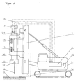
- Die schematische Darstellung eines Vibrationsrammgerätes mit Trägergerät und
- Fig. 2:
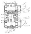
- die schematische Darstellung eines Vibratorgetriebes im Längsschnitt.
- Fig. 1:
- The schematic representation of a vibratory pile driver with carrier and
- Fig. 2:
- the schematic representation of a Vibratorgetriebes in longitudinal section.
Das als Ausführungsbeispiel gewählte Vibrationsrammgerät besteht im Wesentlichen aus einem Trägergerät 1, an dem über einen Mäkler 2 ein Schwingungserzeuger (Vibrator) 3 vertikal verschiebbar angeordnet ist. Der Schwingungserzeuger 3 umfasst ein Gehäuse 31, welches von einer Haube 30 umgeben ist. An der Haube 30 ist eine Klemmzange 37 zur Aufnahme von Rammgut 4 angeordnet. Die Haube 30 dient der Führung des Schwingungserzeugers 3 und überträgt die statische Kraft des Mäklers 2 auf den Schwingungserzeuger 3. Der Schwingungserzeuger 3 generiert über rotierende Unwuchten 3311, 3321, 3331, 3511, 3521, 3531 eine Vibration, welche über die Klemmzange 33 auf das Rammgut 4 übertragen wird.The vibration ramming device chosen as an exemplary embodiment consists essentially of a carrier device 1, on which a vibrator (vibrator) 3 is arranged so as to be vertically displaceable via a broker 2. The
Der Schwingungserzeuger 3 ist als Vibratorgetriebe ausgeführt (
Der Schwingungserzeuger 3 ist gegenüberliegend den Zahnrädern 331, 332, 333, 351, 352, 353 auf der Innenseite des Gehäuses 31 jeweils mit zwei parallel zum Umfang der Zahnräder beabstandet zueinander angeordneten induktiven Sensoren 310 versehen. Die induktiven Sensoren 310 ermöglichen die Erfassung der Winkelbeschleunigung der rotierenden Unwuchtmassen 3311, 3321, 3331, 3511, 3521, 3531. Über den Zeitversatz der Unwuchtmassen 3311, 3321, 3331, 3511, 3521, 3531 lässt sich weiterhin deren relative Position zueinander ermitteln. Des Weiteren ist an dem Gehäuse 31 des Schwingungserzeugers 3 ein Beschleunigungssensor 311 angeordnet. Zur Verarbeitung der Signale der Sensoren 310, 311 und Ermittlung der vorgenannten Größen ist als Auswerteeinheit eine speicherprogrammierbare Steuerung (SPS) 7 angeordnet, welche weiterhin auf Basis von Frequenz und Zeitversatz der Unwuchtmassen zueinander das jeweils anliegende statische Moment berechnet. Alternativ kann auch eine Sensorik mit zwei induktiven Sensoren (also einem induktiven Sensor pro Unwuchtgang) sowie einem auf dem Gehäuse des Schwingungserzeugers angebrachter Beschleunigungssensor vorgesehen sein.The
Die Wellen 33, 35 des Schwingungserzeugers 3 sind mit hydraulischen Antrieben 38 verbunden, die ein veränderbares Schluckvolumen aufweisen. Derartige regelbare Hydraulikantriebe sind in unterschiedlichen Ausführungen bekannt. Die hydraulischen Antriebe 38 sind mit einem Regelmodul verbunden, über welches das Schluckvolumen in Abhängigkeit vom jeweiligen Betriebsdrehzahlbereich einstellbar ist. Im Ausführungsbeispiel ist das Regelmodul in dem Antrieb 38 integriert.The
Der SPS 7 vorgeschaltet ist eine Speichereinheit 10, welche über Leitungen 6 mit der SPS 7 verbunden ist. In der Speichereinheit 10 sind bodenbeschaffenheitsspezifische Vorgabedatensätze mit definierten Betriebskenngrößen hinterlegt. Bei diesen Vorgabegrößen handelt es sich um empirisch ermittelte Größen. Im Ausführungsbeispiel bildet die SPS 7 zusammen mit der Speichereinheit 10 eine Programmautomatik, welche je nach vorliegender Bodenbeschaffenheit einen entsprechenden effizienten Datensatz auswählt. Im Ausführungsbeispiel sind die Datensätze an zu ermittelnde Kraft- und Beschleunigungswerte gekoppelt, welche als Eingangsgrößen der SPS 7 übermittelt werden. Zusätzlich ist als Einflussgröße die Schwingungsemission des umgebenden Eindringmediums hinterlegt.The
Die Ermittlung der Kraft- und Beschleunigungswerte erfolgt über einen Kraftsensor 52 sowie einen Beschleunigungssensor 311. Der Kraftsensor 52 ist derart eingerichtet, dass er die auf das Rammgut 4 einwirkenden Kräfte, die aus der durch den Mäkler 2 aufgebrachten Kräfte sowie der durch das Eindringmedium erzeugten Gegenkraft resultiert, ermittelt und über Leitungen 6 an die SPS 7 übermittelt. Der Beschleunigungssensor 311 ist derart eingerichtet, dass er die Eindringgeschwindigkeit und -beschleunigung des Rammgutes 4 in das Eindringmedium 9 ermittelt und ebenfalls über Leitungen 6 an die SPS 7 übermittelt. Wahlweise kann die Eindringgeschwindigkeit mit einem zusätzlichen Sensor (53) ermittelt werden, vorzugsweise einem Laser zur Abstandsmessung zwischen Vibrator und Boden. Alternativ kann die Ermittlung der anliegenden Kraft auch über einen Beschleunigungssensor 311 und die dynamische Masse erfolgen.The force and acceleration values are determined via a
Zur Ermittlung der Schwingungsemission des das Rammgut 4 umgebenden Bodens 9 ist beabstandet zum Eindringort des Rammgutes 4 ein Schwingungssensor 54 auf den Boden 9 aufgebracht. Dieser Schwingungssensor 54 ermittelt die vom Boden während des Rammvorgangs vom Boden 9 emittierten Schwingungen und übermittelt die erfassten Schwingungswerte über eine Leitung 6 an die SPS 7.In order to determine the vibration emission of the
Auf Basis der so ermittelten Kraft- und Beschleunigungswerte sowie der gemessenen Schwingungswerte wird aus einer Speichereinheit 10 der diesen Werten (bzw. einem Wertebereich, in den die ermittelten Werte fallen) zugeordnete Vorgabe-Datensatz ausgewählt, dessen Vorgabewerte zum Abgleich mit den durch die Sensoren 310, 311 ermittelten Betriebskenngrößen herangezogen werden. In einer alternativen Ausgestaltung ist auch die Auswahl eines Datensatzes durch den Bediener des Vibrationsrammgerätes über ein entsprechendes Bedienfeld möglich.On the basis of the thus determined force and acceleration values as well as the measured vibration values, a default data set assigned to these values (or a range of values into which the determined values fall) is selected from a
In dem Trägergerät 1 ist eine Steuerung 8 angeordnet, welche über Leitungen 6 mit der der Speichereinheit 10 sowie mit der SPS 7 verbunden ist. Die Steuerung 8 ist derart eingerichtet, dass sie aus dem von der SPS 7 ermittelten statischen Moment sowie den von den Sensoren 311 ermittelten Beschleunigungsdaten vor dem Hintergrund der Vorgabekennwerte des aus der Speichereinheit 10 ausgewählten Vorgabe-Datensatzes die optimalen Betriebskenngrößen des Schwingungserzeugers errechnet.In the carrier device 1, a controller 8 is arranged, which is connected via
Die Steuerung 8 ist mit dem in dem Schwingungserzeuger 3 angeordneten Schwenkmotor 36 zur Veränderung der relativen Drehposition der Unwuchtmassen zueinander verbunden. Über die Ansteuerung des Schwenkmotors 36 erfolgt eine Angleichung der aktuellen durch die Sensoren 310, 311 erfassten Betriebskenndaten an die entsprechenden Vorgabewerte des ausgewählten Vorgabedatensatzes. Im Falle der Überschreitung der zulässigen Beschleunigungswerte erfolgt über den Schwenkmotor 36 über das Zahnrad 3621 eine Nachstellung der resultierenden Unwucht bzw. des resultierenden statischen Moments.The controller 8 is connected to the arranged in the
Zusätzlich ist die Installation eines optischen und / oder akustischen Signals im Bedienerstand des Trägergerätes möglich, um den Bediener von der wesentlichen Überschreitung zulässiger Beschleunigungswerte zu informieren. Im Regelfall weist dies auf die Auswahl eines ungeeigneten Betriebskenngrößensatzes aus der Speichereinheit 10 hin. Durch die Aktivierung des Signals wird der Bediener angewiesen, die Auswahl des Vorgabedatensatzes zu überprüfen und gegebenenfalls zu korrigieren.In addition, the installation of an optical and / or acoustic signal in the operator's stand of the carrier device is possible to inform the operator of the significant exceeding of allowable acceleration values. As a rule, this indicates the selection of an unsuitable operating characteristic quantity set from the
Claims (13)
Priority Applications (3)
| Application Number | Priority Date | Filing Date | Title |
|---|---|---|---|
| DE200820017313 DE202008017313U1 (en) | 2008-01-29 | 2008-01-29 | Vibration generator for vibratory pile driver |
| EP08001601.7A EP2085149B2 (en) | 2008-01-29 | 2008-01-29 | Vibrator for a vibratory pile driver |
| US12/290,104 US8522891B2 (en) | 2008-01-29 | 2008-10-27 | Vibration generator for a vibration pile driver |
Applications Claiming Priority (1)
| Application Number | Priority Date | Filing Date | Title |
|---|---|---|---|
| EP08001601.7A EP2085149B2 (en) | 2008-01-29 | 2008-01-29 | Vibrator for a vibratory pile driver |
Publications (3)
| Publication Number | Publication Date |
|---|---|
| EP2085149A1 true EP2085149A1 (en) | 2009-08-05 |
| EP2085149B1 EP2085149B1 (en) | 2013-07-24 |
| EP2085149B2 EP2085149B2 (en) | 2021-12-22 |
Family
ID=39365417
Family Applications (1)
| Application Number | Title | Priority Date | Filing Date |
|---|---|---|---|
| EP08001601.7A Active EP2085149B2 (en) | 2008-01-29 | 2008-01-29 | Vibrator for a vibratory pile driver |
Country Status (2)
| Country | Link |
|---|---|
| US (1) | US8522891B2 (en) |
| EP (1) | EP2085149B2 (en) |
Cited By (5)
| Publication number | Priority date | Publication date | Assignee | Title |
|---|---|---|---|---|
| EP2557233A1 (en) | 2011-08-12 | 2013-02-13 | ABI Anlagentechnik-Baumaschinen-Industriebedarf Maschinenfabrik und Vertriebsgesellschaft mbH | Tool with hydraulic drive for civil engineering work |
| EP2789402A1 (en) * | 2013-04-10 | 2014-10-15 | ABI Anlagentechnik-Baumaschinen-Industriebedarf Maschinenfabrik und Vertriebsgesellschaft mbH | Oscillation exciter |
| US9289799B2 (en) | 2013-04-10 | 2016-03-22 | Abi Anlagentechnik-Baumaschinen-Industriebedarf Maschinenfabrik Und Vertriebsgesellschaft Mbh | Vibration exciter for construction machines |
| EP3243573A1 (en) | 2016-05-09 | 2017-11-15 | Eurodrill GmbH | Vibration generator |
| US10385883B2 (en) | 2013-04-12 | 2019-08-20 | Thyssenkrupp Infrastructure Gmbh | Vibrating ram arrangement, and method for operating the vibrating ram arrangement |
Families Citing this family (7)
| Publication number | Priority date | Publication date | Assignee | Title |
|---|---|---|---|---|
| EP2085148B1 (en) * | 2008-01-29 | 2013-09-18 | ABI Anlagentechnik-Baumaschinen-Industriebedarf Maschinenfabrik und Vertriebsgesellschaft mbH | Vibrator for a vibratory pile driver |
| EP3101179B1 (en) | 2015-06-03 | 2018-04-18 | ABI Anlagentechnik-Baumaschinen-Industriebedarf Maschinenfabrik und Vertriebsgesellschaft mbH | Working machine, especially for a construction machine |
| DE102015008015A1 (en) * | 2015-06-22 | 2016-12-22 | Liebherr-Werk Nenzing Gmbh | Method for controlling a vibratory hammer |
| US11015315B2 (en) * | 2015-10-12 | 2021-05-25 | Yeow Thium Chin | Pile set measurement apparatus |
| JP6602643B2 (en) * | 2015-10-29 | 2019-11-06 | 西松建設株式会社 | Vibration measurement management system and pile foundation construction method |
| DE102017001877A1 (en) * | 2017-02-27 | 2018-08-30 | Liebherr-Werk Nenzing Gmbh | Method for detecting obstacles during operation of a vibrating hammer |
| US20220106760A1 (en) * | 2019-02-12 | 2022-04-07 | Jia Yi Chin | Pile set measurement apparatus |
Citations (6)
| Publication number | Priority date | Publication date | Assignee | Title |
|---|---|---|---|---|
| DE4301368A1 (en) * | 1992-07-03 | 1994-01-05 | Gedib Ingbuero Innovation | Device and method for exciting vibrations |
| EP0577444A1 (en) * | 1992-06-19 | 1994-01-05 | Procedes Techniques De Construction | Control device of a vibrator with variable imbalance |
| DE19543910A1 (en) * | 1995-11-26 | 1997-05-28 | Gedib Ingbuero Innovation | Adjustment device for an unbalance directional oscillator with adjustable centrifugal moment |
| EP0951949A1 (en) * | 1998-04-22 | 1999-10-27 | International Construction Equipment B.V. | Method and device for vibratory driving of an object |
| EP1722036A2 (en) | 2005-05-11 | 2006-11-15 | Ammann Verdichtung GmbH | Ground compacting machine |
| DE202007005283U1 (en) | 2007-03-07 | 2007-07-12 | Abi Gmbh | vibration exciter |
Family Cites Families (19)
| Publication number | Priority date | Publication date | Assignee | Title |
|---|---|---|---|---|
| DE2442367A1 (en) * | 1974-09-04 | 1976-03-18 | Tracto Technik | HYDRAULICALLY DRIVEN VIBRATOR |
| US4211121A (en) * | 1976-09-01 | 1980-07-08 | Fmc Corporation | Vibrator with eccentric weights |
| US4113034A (en) * | 1977-06-20 | 1978-09-12 | Raygo, Inc. | Uniaxial variable vibratory force generator |
| DE2732934C2 (en) * | 1977-07-21 | 1985-09-12 | Bomag-Menck GmbH, 5407 Boppard | Method and device for ramming and pulling |
| DE3043719A1 (en) * | 1980-11-20 | 1982-06-24 | Wacker-Werke Gmbh & Co Kg, 8077 Reichertshofen | Vibration exciter for soil compacting devices |
| US4766771A (en) * | 1984-11-15 | 1988-08-30 | Outboard Marine Corporation | Shaking apparatus |
| US4793196A (en) * | 1987-03-24 | 1988-12-27 | Key Technology, Inc. | Gear coupled, counter-rotating vibratory drive assembly |
| US4819740A (en) * | 1987-11-16 | 1989-04-11 | Vulcan Iron Works Inc. | Vibratory hammer/extractor |
| US5177386A (en) * | 1990-08-30 | 1993-01-05 | Kencho Kobe Co., Ltd. | Vibration generator adjustable during operation |
| US5375664A (en) * | 1993-06-15 | 1994-12-27 | Mcdowell; Michael M. | Pile driver |
| US5355964A (en) † | 1993-07-12 | 1994-10-18 | White John L | Pile driving and/or pile pulling vibratory assembly with counterweights |
| DE4425905A1 (en) * | 1994-07-21 | 1996-01-25 | Bald Hubert | Device and method for compensating transverse vibrations on unbalance vibrators with a predetermined vibration direction |
| GB2305488B (en) † | 1995-09-21 | 1999-04-28 | Moog Inc | Modular vibratory force generator, and method of operating same |
| FR2772805B1 (en) * | 1997-12-24 | 2000-02-25 | Procedes Tech Const | DEVICE FOR CONTROLLING THE AMPLITUDE OF THE VIBRATIONS OF A VARIABLE MOMENT |
| NL1008635C2 (en) * | 1998-03-19 | 1999-09-21 | Ice B V | Vibrating device and method for vibrating an object. |
| US6182925B1 (en) † | 1999-03-30 | 2001-02-06 | The Boeing Company | Semi-levered landing gear and auxiliary strut therefor |
| US6769838B2 (en) * | 2001-10-31 | 2004-08-03 | Caterpillar Paving Products Inc | Variable vibratory mechanism |
| US7404449B2 (en) * | 2003-05-12 | 2008-07-29 | Bermingham Construction Limited | Pile driving control apparatus and pile driving system |
| EP2085148B1 (en) * | 2008-01-29 | 2013-09-18 | ABI Anlagentechnik-Baumaschinen-Industriebedarf Maschinenfabrik und Vertriebsgesellschaft mbH | Vibrator for a vibratory pile driver |
-
2008
- 2008-01-29 EP EP08001601.7A patent/EP2085149B2/en active Active
- 2008-10-27 US US12/290,104 patent/US8522891B2/en active Active
Patent Citations (6)
| Publication number | Priority date | Publication date | Assignee | Title |
|---|---|---|---|---|
| EP0577444A1 (en) * | 1992-06-19 | 1994-01-05 | Procedes Techniques De Construction | Control device of a vibrator with variable imbalance |
| DE4301368A1 (en) * | 1992-07-03 | 1994-01-05 | Gedib Ingbuero Innovation | Device and method for exciting vibrations |
| DE19543910A1 (en) * | 1995-11-26 | 1997-05-28 | Gedib Ingbuero Innovation | Adjustment device for an unbalance directional oscillator with adjustable centrifugal moment |
| EP0951949A1 (en) * | 1998-04-22 | 1999-10-27 | International Construction Equipment B.V. | Method and device for vibratory driving of an object |
| EP1722036A2 (en) | 2005-05-11 | 2006-11-15 | Ammann Verdichtung GmbH | Ground compacting machine |
| DE202007005283U1 (en) | 2007-03-07 | 2007-07-12 | Abi Gmbh | vibration exciter |
Cited By (7)
| Publication number | Priority date | Publication date | Assignee | Title |
|---|---|---|---|---|
| EP2557233A1 (en) | 2011-08-12 | 2013-02-13 | ABI Anlagentechnik-Baumaschinen-Industriebedarf Maschinenfabrik und Vertriebsgesellschaft mbH | Tool with hydraulic drive for civil engineering work |
| US9399850B2 (en) | 2011-08-12 | 2016-07-26 | ABI Anlagentechnik-Baumaschinen-Industriebedarf Maschinefabrik und Vertriebsgesellschaft mbH | Device having a hydraulic drive for civil engineering |
| EP2789402A1 (en) * | 2013-04-10 | 2014-10-15 | ABI Anlagentechnik-Baumaschinen-Industriebedarf Maschinenfabrik und Vertriebsgesellschaft mbH | Oscillation exciter |
| US9289799B2 (en) | 2013-04-10 | 2016-03-22 | Abi Anlagentechnik-Baumaschinen-Industriebedarf Maschinenfabrik Und Vertriebsgesellschaft Mbh | Vibration exciter for construction machines |
| EP2789402B1 (en) | 2013-04-10 | 2017-05-17 | ABI Anlagentechnik-Baumaschinen-Industriebedarf Maschinenfabrik und Vertriebsgesellschaft mbH | Oscillation exciter |
| US10385883B2 (en) | 2013-04-12 | 2019-08-20 | Thyssenkrupp Infrastructure Gmbh | Vibrating ram arrangement, and method for operating the vibrating ram arrangement |
| EP3243573A1 (en) | 2016-05-09 | 2017-11-15 | Eurodrill GmbH | Vibration generator |
Also Published As
| Publication number | Publication date |
|---|---|
| US20090189467A1 (en) | 2009-07-30 |
| EP2085149B1 (en) | 2013-07-24 |
| EP2085149B2 (en) | 2021-12-22 |
| US8522891B2 (en) | 2013-09-03 |
Similar Documents
| Publication | Publication Date | Title |
|---|---|---|
| EP2085149B1 (en) | Vibrator for a vibratory pile driver | |
| EP2085148B1 (en) | Vibrator for a vibratory pile driver | |
| DE102015006398B3 (en) | Soil compaction with a dredger cultivator | |
| EP2928611B1 (en) | Drive control method and drive system operating according to said method | |
| EP3252232B2 (en) | Soil compactor and method for operating same | |
| EP2627826B1 (en) | Method for determinig the rigidity and/or the damping of the region of a solidity | |
| DE10235976B4 (en) | Variable vibration mechanism | |
| DE102005036842A1 (en) | Control system and control method for a vibration mechanism | |
| EP2984241B1 (en) | Vibrating driving arrangement, and method for operating the vibrating driving arrangement | |
| DE102014001885A1 (en) | Method for optimizing an operating function of a ground milling machine and ground milling machine | |
| DE2949237A1 (en) | TRACTOR WITH CONTROL DEVICE | |
| EP2558645B1 (en) | Method for operating a milling machine with a vertically adjustable milling drum | |
| EP2557233B2 (en) | Tool with hydraulic drive for civil engineering work | |
| EP1722036A2 (en) | Ground compacting machine | |
| WO2008128619A1 (en) | Vibrator for a ground compacting apparatus | |
| EP2067533B2 (en) | Vibrator for a vibratory pile driver | |
| EP3587668A1 (en) | Self-propelled construction machine and method for processing floor linings | |
| EP3383543B1 (en) | Method for adjusting a crushing nip | |
| DE19543910A1 (en) | Adjustment device for an unbalance directional oscillator with adjustable centrifugal moment | |
| DE10220057B4 (en) | Device for compensation of vibrations caused by inertial forces | |
| DE102018001505A1 (en) | Method for machining a workpiece by means of an articulated robot | |
| DE202008017313U1 (en) | Vibration generator for vibratory pile driver | |
| EP3819434B1 (en) | Method and wall milling device for creating a milled slot in the ground | |
| WO2017045918A1 (en) | Method for operating a tube mill, assembly for determining characteristic data of a tube mill, and tube mill | |
| DE202007019293U1 (en) | Vibration generator for soil compacting devices |
Legal Events
| Date | Code | Title | Description |
|---|---|---|---|
| PUAI | Public reference made under article 153(3) epc to a published international application that has entered the european phase |
Free format text: ORIGINAL CODE: 0009012 |
|
| 17P | Request for examination filed |
Effective date: 20080913 |
|
| AK | Designated contracting states |
Kind code of ref document: A1 Designated state(s): AT BE BG CH CY CZ DE DK EE ES FI FR GB GR HR HU IE IS IT LI LT LU LV MC MT NL NO PL PT RO SE SI SK TR |
|
| AX | Request for extension of the european patent |
Extension state: AL BA MK RS |
|
| AKX | Designation fees paid |
Designated state(s): DE FR GB NL |
|
| 17Q | First examination report despatched |
Effective date: 20101026 |
|
| GRAP | Despatch of communication of intention to grant a patent |
Free format text: ORIGINAL CODE: EPIDOSNIGR1 |
|
| GRAS | Grant fee paid |
Free format text: ORIGINAL CODE: EPIDOSNIGR3 |
|
| INTG | Intention to grant announced |
Effective date: 20130522 |
|
| GRAA | (expected) grant |
Free format text: ORIGINAL CODE: 0009210 |
|
| STAA | Information on the status of an ep patent application or granted ep patent |
Free format text: STATUS: THE PATENT HAS BEEN GRANTED |
|
| AK | Designated contracting states |
Kind code of ref document: B1 Designated state(s): DE FR GB NL |
|
| REG | Reference to a national code |
Ref country code: GB Ref legal event code: FG4D Free format text: NOT ENGLISH |
|
| REG | Reference to a national code |
Ref country code: NL Ref legal event code: T3 |
|
| REG | Reference to a national code |
Ref country code: DE Ref legal event code: R096 Ref document number: 502008010347 Country of ref document: DE Effective date: 20130919 |
|
| PLBI | Opposition filed |
Free format text: ORIGINAL CODE: 0009260 |
|
| 26 | Opposition filed |
Opponent name: BAUER MASCHINEN GMBH Effective date: 20140407 |
|
| PLAX | Notice of opposition and request to file observation + time limit sent |
Free format text: ORIGINAL CODE: EPIDOSNOBS2 |
|
| REG | Reference to a national code |
Ref country code: DE Ref legal event code: R026 Ref document number: 502008010347 Country of ref document: DE Effective date: 20140407 |
|
| PLBB | Reply of patent proprietor to notice(s) of opposition received |
Free format text: ORIGINAL CODE: EPIDOSNOBS3 |
|
| REG | Reference to a national code |
Ref country code: FR Ref legal event code: PLFP Year of fee payment: 9 |
|
| RDAF | Communication despatched that patent is revoked |
Free format text: ORIGINAL CODE: EPIDOSNREV1 |
|
| APBM | Appeal reference recorded |
Free format text: ORIGINAL CODE: EPIDOSNREFNO |
|
| APBP | Date of receipt of notice of appeal recorded |
Free format text: ORIGINAL CODE: EPIDOSNNOA2O |
|
| APAH | Appeal reference modified |
Free format text: ORIGINAL CODE: EPIDOSCREFNO |
|
| APBQ | Date of receipt of statement of grounds of appeal recorded |
Free format text: ORIGINAL CODE: EPIDOSNNOA3O |
|
| REG | Reference to a national code |
Ref country code: FR Ref legal event code: PLFP Year of fee payment: 10 |
|
| REG | Reference to a national code |
Ref country code: FR Ref legal event code: PLFP Year of fee payment: 11 |
|
| PLAB | Opposition data, opponent's data or that of the opponent's representative modified |
Free format text: ORIGINAL CODE: 0009299OPPO |
|
| R26 | Opposition filed (corrected) |
Opponent name: BAUER MASCHINEN GMBH Effective date: 20140407 |
|
| APBU | Appeal procedure closed |
Free format text: ORIGINAL CODE: EPIDOSNNOA9O |
|
| PUAH | Patent maintained in amended form |
Free format text: ORIGINAL CODE: 0009272 |
|
| STAA | Information on the status of an ep patent application or granted ep patent |
Free format text: STATUS: PATENT MAINTAINED AS AMENDED |
|
| 27A | Patent maintained in amended form |
Effective date: 20211222 |
|
| AK | Designated contracting states |
Kind code of ref document: B2 Designated state(s): DE FR GB NL |
|
| REG | Reference to a national code |
Ref country code: DE Ref legal event code: R102 Ref document number: 502008010347 Country of ref document: DE |
|
| REG | Reference to a national code |
Ref country code: NL Ref legal event code: FP |
|
| PGFP | Annual fee paid to national office [announced via postgrant information from national office to epo] |
Ref country code: GB Payment date: 20220125 Year of fee payment: 15 |
|
| PGFP | Annual fee paid to national office [announced via postgrant information from national office to epo] |
Ref country code: FR Payment date: 20230123 Year of fee payment: 16 |
|
| PGFP | Annual fee paid to national office [announced via postgrant information from national office to epo] |
Ref country code: DE Payment date: 20221230 Year of fee payment: 16 |
|
| P01 | Opt-out of the competence of the unified patent court (upc) registered |
Effective date: 20230513 |
|
| PGFP | Annual fee paid to national office [announced via postgrant information from national office to epo] |
Ref country code: NL Payment date: 20230124 Year of fee payment: 16 |
|
| GBPC | Gb: european patent ceased through non-payment of renewal fee |
Effective date: 20230129 |
|
| PG25 | Lapsed in a contracting state [announced via postgrant information from national office to epo] |
Ref country code: GB Free format text: LAPSE BECAUSE OF NON-PAYMENT OF DUE FEES Effective date: 20230129 |
|
| PGFP | Annual fee paid to national office [announced via postgrant information from national office to epo] |
Ref country code: NL Payment date: 20240123 Year of fee payment: 17 |