EP0577444A1 - Control device of a vibrator with variable imbalance - Google Patents
Control device of a vibrator with variable imbalance Download PDFInfo
- Publication number
- EP0577444A1 EP0577444A1 EP93401253A EP93401253A EP0577444A1 EP 0577444 A1 EP0577444 A1 EP 0577444A1 EP 93401253 A EP93401253 A EP 93401253A EP 93401253 A EP93401253 A EP 93401253A EP 0577444 A1 EP0577444 A1 EP 0577444A1
- Authority
- EP
- European Patent Office
- Prior art keywords
- pressure
- rephasing
- distributor
- chamber
- phase shift
- Prior art date
- Legal status (The legal status is an assumption and is not a legal conclusion. Google has not performed a legal analysis and makes no representation as to the accuracy of the status listed.)
- Withdrawn
Links
Images


Classifications
-
- B—PERFORMING OPERATIONS; TRANSPORTING
- B06—GENERATING OR TRANSMITTING MECHANICAL VIBRATIONS IN GENERAL
- B06B—METHODS OR APPARATUS FOR GENERATING OR TRANSMITTING MECHANICAL VIBRATIONS OF INFRASONIC, SONIC, OR ULTRASONIC FREQUENCY, e.g. FOR PERFORMING MECHANICAL WORK IN GENERAL
- B06B1/00—Methods or apparatus for generating mechanical vibrations of infrasonic, sonic, or ultrasonic frequency
- B06B1/10—Methods or apparatus for generating mechanical vibrations of infrasonic, sonic, or ultrasonic frequency making use of mechanical energy
- B06B1/16—Methods or apparatus for generating mechanical vibrations of infrasonic, sonic, or ultrasonic frequency making use of mechanical energy operating with systems involving rotary unbalanced masses
- B06B1/161—Adjustable systems, i.e. where amplitude or direction of frequency of vibration can be varied
- B06B1/166—Where the phase-angle of masses mounted on counter-rotating shafts can be varied, e.g. variation of the vibration phase
-
- Y—GENERAL TAGGING OF NEW TECHNOLOGICAL DEVELOPMENTS; GENERAL TAGGING OF CROSS-SECTIONAL TECHNOLOGIES SPANNING OVER SEVERAL SECTIONS OF THE IPC; TECHNICAL SUBJECTS COVERED BY FORMER USPC CROSS-REFERENCE ART COLLECTIONS [XRACs] AND DIGESTS
- Y10—TECHNICAL SUBJECTS COVERED BY FORMER USPC
- Y10T—TECHNICAL SUBJECTS COVERED BY FORMER US CLASSIFICATION
- Y10T74/00—Machine element or mechanism
- Y10T74/18—Mechanical movements
- Y10T74/18056—Rotary to or from reciprocating or oscillating
- Y10T74/18344—Unbalanced weights
Definitions
- the present invention relates to a device for controlling a variable-time vibrator such as, for example, that described in patent application No. 91 09253, of July 15, 1991, in the name of the Applicant.
- vibrators of this kind which are used, for example, for driving objects such as piles or sheet piles into the ground, involve at least a couple of eccentric rotating weights, or even two sets of weights driven in opposite direction to each other, at the same speed of rotation.
- Such devices can involve a planetary gear train, of the Pecqueur type, such as described in patent No. 1,566,358, in the name of the Applicant, or even a rotary link involving a hydraulic phase shifter, for example of the type comprising two rotary elements movable axially with respect to each other and against the action of a spring, under the effect of a pressurized fluid.
- this device is characterized in that said first distribution circuit comprises first limiting means making it possible, thanks to a control member, to vary the pressure which it applies to said chamber within a predetermined range, and in that the other chamber is connected to a second distribution circuit comprising means making it possible to modulate the pressure which it applies to this second chamber, according to an appropriate counter-profile, so that the actuator applies to the phase shifter a motor force in relation to the resistance force which results from the amplitude of the movement of the vibrator and that thus, to each value displayed on the control member, corresponds a determined amplitude of the vibrations.
- the distributor is put in the rest position when starting the engine associated with the auxiliary hydraulic pump which supplies the phase shifter and then in the rephasing position when certain conditions are met, for example when the flow rate of the main hydraulic pump which supplies the vibrator reaches a predetermined minimum value (for example a flow rate corresponding to a minimum frequency of the vibrator).
- a predetermined minimum value for example a flow rate corresponding to a minimum frequency of the vibrator.
- Another advantage of the device described above consists in that it makes it possible to get rid of nuisances due to decreases in frequency of the vibrator resulting for example from an evacuation of part of the flow by the triggering of a high pressure valve.
- the perception of the pressure drop below the critical pressure leads to a reverse tilting of the main distributor (method i)), of the second distributor (method ii)), and, consequently, a phase shift of the phase shifter and a redeployment of the moment.
- the vibrator then has both the power delivered by the hydraulic motors and the kinetic energy accumulated in the flyweights.
- Adjustment of the pumping period can be obtained by adjusting the switching thresholds for high pressure and / or exhaust pressure (method ii)).
- Another advantage of the device described above is that it allows the control of the amplitude control, either at a sound level measured on the site, or at a vibratory amplitude level measured in the ground or on a structure. .
- the vibrator comprises two trains 1, 2 of eccentric weights rotatably mounted by means of shafts A1, A2, A n - A'1, A'2, A ' n parallel to a transverse axis X, X 'and the ends of which engage in bearings carried by two parallel flanges 3, 4 constituting the two lateral sides of a housing 5.
- Each of the weights M, M ′ is associated with a pinion P arranged and dimensioned so that the pinions P associated with the same train 1, 2 of weights M mesh with each other, in successive pairs.
- each set of counterweights M comprises a pair of sets of counterweights M / pinion P shown in solid lines, the set partially represented in broken lines indicating the mode of implantation of another pair.
- the two flywheel trains are driven in rotation by means of a motorization, comprising two hydraulic motors H1, H2 mounted on the flange 3 at one end of the housing 5.
- the pinions P1 and P6 respectively mesh with the pinions P associated with the flyweights M 'and M to carry out the rotational drive of the trains 2 and 1.
- the pinion P5 is arranged so as to mesh with a pinion P3 secured to the driven shaft 6 of a phase shifter 7 with hydraulic control.
- This phase shifter 7 further comprises a driving shaft 8, coaxial with the driven shaft 6, which carries a pinion P4 engaged with the pinion P2 driven by the motor H1.
- phase shifter control device has been shown schematically in the form of a double-acting hydraulic cylinder 11 whose rod 12 which is integral with the piston 13 actuates a phase shift mechanism which may include a planetary gear train of Pecqueur or even a rotary link comprising two rotary elements axially movable relative to each other.
- a phase shift mechanism which may include a planetary gear train of Pecqueur or even a rotary link comprising two rotary elements axially movable relative to each other.
- at least one of these elements has a helical groove which cooperates with a part of the other element so that an axial displacement of one of the two elements relative to the other, for example under the effect of the rod 12 generates a relative rotation of these two elements.
- the phase shift circuit 17 which comprises a non-return valve 20 is connected to one S1 of the three outputs S1, S2, S3 of a distributor 21 whose input E is connected to the output of a driven hydraulic pump 22 by a diesel engine 23 and of which an output S3 is connected to the cover B by a return circuit to the cover 29.
- the pressure of the hydraulic fluid applied to the inlet E of the distributor 21 is limited to a safety value by means of a circuit for returning to the tank comprising a pressure switch 24 calibrated for example at a pressure below the maximum admissible pressure in the rest of the phase shift and / or rephasing circuit.
- the output S1 of the distributor 21 is connected to the return circuit 29 by means of a pressure switch P04 calibrated for example at a value chosen as a function of the desired low pressure in the accumulator and the phase shift chamber.
- the motor 23 also drives a second, more powerful hydraulic pump P, intended to supply the hydraulic motors of the vibrator.
- the rephasing circuit 19 which is connected to a second outlet S2 of the distributor 21 comprises, in series, a distributor 25 and a pressure regulator 26 allowing, by virtue of a potentiometric control 27, to vary the pressure of the fluid injected into the chamber rephasing 18 in a pressure range [P1, P2].
- the phase shift chamber 16 of the cylinder 11 is, moreover, connected to a hydraulic accumulator 31 whose hydraulic pressure increases as the volume of oil present in the phase shift chamber 16 is transferred from the cylinder 11 into the accumulator 31.
- this accumulator 31 is used in combination with the pressure regulator 26 so that at each pressure value of the hydraulic fluid supplied by the regulator 26 corresponds to a position of the piston 13 in the cylinder 11, and a corresponding phase shift of the phase shifter.
- the distributor 25 provides a connection between the pressure regulator 26 and the rephasing chamber 18 or between the latter and the circuit 29 for returning to the tank B, by means of a pressure switch P05 calibrated for example to ensure proper braking of the oil discharged from the rephasing chamber.
- the pressure admitted into the latter is clipped to a value P'02 thanks to a pressure limiter D set to a judiciously chosen value, less than P2 (maximum value of the pressure delivered by the regulator).
- This limiter D short-circuits the valve 22 so as to allow, in all circumstances, a phase shift of the phase shifter and, consequently, a complete deployment of the moment of the vibrator.
- the device described above makes it possible to solve in a particularly advantageous manner the operating phases which, until now, were critical, such as starting the diesel engine 23, starting the vibrations, stopping the vibrations and sinking in hard ground.
- the starting of the diesel engine 23 can be carried out when empty, with the counterweight trains in phase opposition (zero moment).
- the automatic placing in position 1 of the distributor and, consequently, the phase shift of the phase shifter is dependent on the launch of the diesel engine 23
- a servo-control of the accelerator position or a sensor 35 of the speed of rotation of the motor 23 which acts on the distributor 21 (link 36 in dashed lines) when the speed of rotation of the motor 23 exceeds a predetermined threshold.
- This arrangement also makes it possible to place the counterweight trains of the vibrator in phase opposition and therefore perform a launch of this vibrator without triggering vibration.
- the tilting of the distributor 21 in position 2 is electrically subordinated to the obtaining of a minimum hydraulic flow (in general, a flow which corresponds to the minimum frequency of vibration) in the hydraulic circuit main powering the hydraulic motors of the vibrator.
- a minimum hydraulic flow in general, a flow which corresponds to the minimum frequency of vibration
- this sensor 37 can automatically switch the distributor to position 2 as soon as the above threshold is crossed or, on the contrary, automatically switch the distributor to position 1 when the flow rate falls below the above threshold and, in a more general, as soon as the frequency conditions are no longer met, in particular as soon as a reduction in the main flow is manually controlled. This process, which occurs during the shutdown phase, avoids the low frequency vibrations that usually occur during this phase.
- An important feature of the device described above is that it allows the vibrator to be used in overpowering by exploiting a pumping phenomenon usually considered harmful.
- the vibrator has both the power delivered by the hydraulic transmission and the kinetic energy accumulated in the flyweights. Until the critical pressure is reached again.
- Figure 4 shows the block diagram of an electrical control circuit associated with the hydraulic circuit previously described.
- the switching device 47 comprises a first switch 49 in series with a switch 50, a first output 51 of which is connected to the solenoid 43 which controls the position 1 of the distributor 21 and of which a second output 52 is connected to the switch 48.
- a pumping process of the type described above is therefore obtained, the amplitude of which can be adjusted by electronic or mechanical means acting on the difference between the threshold values of the pressure of the hydraulic fluid delivered by the hydraulic pump.
- Another important advantage of the device described above is that it makes it possible to control the amplitude control, either at a noise level, or at a vibratory amplitude level measured in the ground in particular in order to comply with the standards. noise or vibration at the site boundary.
- a device 60 performing the measurement of noise or vibrations.
- the result of this measurement is compared with a setpoint V in a comparator.
- the latter acts on the pressure regulator, so as to establish an appropriate phase shift tending to cancel the difference between the measured value and the set value.
- a connector network 61 for example of the PID type, can be used this time to avoid oscillations and to maintain the performance of the device at maximum compatible with the set values.
- variable moment vibrator which has been represented diagrammatically by a block in broken lines 70 comprises two hydraulic motors 71, 72 supplied by a generator of pressurized hydraulic fluid 73 comprising two pump bodies 74 , 75 driven by an engine 76, for example a diesel engine.
- the flow rate of this generator 73 is controlled by a servo-control device 77 controlled by a potentiometer 78.
- the phase shifter 79 is controlled by a hydraulic circuit supplied by an auxiliary pump 80 driven by the motor 76.
- This auxiliary pump 80 delivers on a mechanical pressure limiter 81 which maintains a pressure Pr equal to a value corresponding to the rephasing pressure.
- the output of this limiter 81 is connected to the rephasing chamber 82 of the phase shifter via an electromechanical distributor 83 which is in the on state, in the rest position and which diverts the flow of oil towards the tank. 84 when its coil 85 is energized.
- the hydraulic fluid delivered by the auxiliary pump 80 which is moreover controlled by a pressure limiter 86 which limits the maximum control pressure to a value Pmax, is applied to a second electrically controlled pressure reducer 87, which delivers of the fluid at a pressure adjustable between a maximum phase shift pressure Pdmax and a minimum phase shift pressure Pdmin by virtue of an electronic control circuit controlled by a potentiometer 88.
- the output of this reducer 87 is connected to the phase shift chamber 89 of the phase shifter 79.
- an electrical control circuit supplied by a direct current source which supplies, on the one hand, the electronic circuit 90 of the pressure regulator allowing potentiometric adjustment (potentiometer 88) of the pressure. applied to the phase shift chamber 89 as well as, on the other hand, the electromagnet 85 of the distributor 83 via a switching circuit comprising a relay 91 on which is mounted in parallel a pressure switch 92 which closes when the pressure of the fluid delivered by the two pump bodies is greater than or equal to a pressure PM.
- This control circuit also involves a rotary selector 93 mechanically coupled to the potentiometer 78 and whose rotary cursor 94 scans and temporarily switches a plurality of contacts (here the contacts C1, C2, C3) as it is rotated.
- the cursor 94 is connected to the negative pole of the power source.
- the contact C2 is connected to the positive pole of the power supply via the coil KA2 of a relay 95 which controls the application of the positive pole to one of the ends of the coil KA3 of the relay 91.
- Contact C3 is connected to the other end of coil KA3 of relay 91.
- the rephasing circuit is connected to the cover 84, and only the phase shift chamber 89 is supplied (with at least the minimum phase shift pressure Pdmin) and, therefore, the vibrator 70 does not generate any vibration amplitude.
- the phase shift chamber 82 is, for its part, supplied with fluid, the pressure of which is between the maximum and minimum phase shift pressures.
- phase shifter 79 When the phase shift pressure is at its maximum (by convention, zero position of the potentiometer 88) then the phase shifter 79 is subjected to a resultant phase shift pressure (difference between the maximum phase shift pressure and the phase shift pressure). Because the phase shifter 79 was initially in the completely phase-shifted state and the rephasing requiring a resultant rephasing pressure sufficient to overcome friction and the resistance to the creation of vibrations, no vibration is able to be established.
- the rephasing chamber 82 is maintained at the rephasing pressure while the pressure in the phase shift chamber 89 drops below this rephasing pressure.
- the resulting pressure is therefore a rephasing pressure and, consequently, the phase shifter resumes rephasing the weights of the vibrator 70 until the amplitude of vibration generated by the latter dynamically generates a relative torque opposing the torque exerted. by the phase shifter 79 under the effect of the resulting pressure.
- the displacements of the phase shifter 79 and the values applied are chosen so as to obtain the maximum useful amplitude for a complete rephasing of the two counterweight trains when the dephasing backpressure reaches its minimum value.
- the choice of the minimum phase shift pressure is that which makes it possible to obtain a complete phase shift of the flyweights in the absence of rephasing pressure.
- a pressure limiter calibrated to the maximum phase shift pressure value is mounted on the rephasing circuit to limit the pressure peaks observed when under the effect of the maximum phase shift pressure, the fluid contained in the rephasing chamber 82 is found turned back towards the tarpaulin 84.
- the contact C1 of the rotary selector 93 which corresponds to the zero of the potentiometer 78 and therefore to a zero flow rate, is used for starting safety (prohibition of starting the generator of hydraulic fluid under pressure 73 if the pumps 74, 75 are not at zero flow, to avoid starting the engine 76 under load and turning the weights during this start).
- the contact C2 corresponds to a position of the potentiometer 78 controlling a speed close to the minimum vibration speed, for example 1650 rpm below which it is desired to prohibit any vibration whose frequency would be insufficient and therefore harmful.
- the relay 95 goes to the excited state while relay 91 remains at rest.
- the coil 85 of the distributor 83 therefore remains in the excited state.
- Contact C3 corresponds to a position of potentiometer 78 controlling the minimum vibration speed, for example 1800 rpm.
- the relay 95 is at rest while the relay 91 goes to the excited state (with self-hold) by interrupting the supply of the coil 85 of the distributor 83, which switches ensuring the connection of the output of the limiter 81 to the rephasing chamber 82.
- the pressure switch 92 makes it possible to close the circuit of the distributor coil, and therefore to activate it, when the pressure of the hydraulic fluid of the two pump bodies 74, 75 reaches the maximum admissible hydraulic pressure (this pressure is associated with the maximum available power inherent in the heat engine).
- the coil 85 of the distributor 83 is energized, which prohibits the establishment of the rephasing pressure and therefore of any vibration.
- the coil 85 When the minimum vibration speed is reached and exceeded, the coil 85 is in the de-energized state and the vibration amplitude is established at the level controlled by the potentiometer 88, determining the position of the pressure reducer 87.
- the coil 85 of the distributor 83 will be excited by the return of the electromagnet 91 to the rest position. Consequently, the distributor 83 will trigger the reduction and the suppression of the vibratory amplitude, whatever the position of the potentiometer 88 for controlling the amplitude, thus allowing the machine to stop without vibrating.
- the return torque towards the phase shift of the weights is all the more important as the ground resists and causes the pressure generated by the two pump bodies 74, 75 to increase.
- This torque is added to the only phase shift pressure controlled by the potentiometer 88. It acts on the phase shifter 79 to quickly phase shift the weights and thus reduce the amplitude of the vibrator 70 and, consequently, the power necessary for the maintenance of the vibration, therefore the pressure called by the hydraulic motors 71, 72 of the vibrator 70.
- the hydraulic efficiency of the generator 73 improves and the speed of the motor 76 increases by a few hundred additional revolutions per minute.
- the rotary assembly therefore accumulates kinetic energy at the same time as the pressure switch 92 which causes the switching of the distributor 83.
- the latter restores the supply of the rephasing pressure which will quickly put the weights back in phase.
- the vibrator 70 delivers to the ground the maximum power delivered by the generator 73 and the power associated with the excess kinetic energy of rotation of the flyweights whose rotation speed decreases by a few hundred revolutions in a few tenths seconds until the pressure again exceeds the maximum allowable pressure.
- This pulsation phenomenon makes it possible to prevent the vibrator 70 working on hard floors from dropping significantly in frequency (fall limited to 10%) unlike traditional vibrators which lose up to 50% of their frequency. The performance of the machine is therefore improved.
Landscapes
- Engineering & Computer Science (AREA)
- Mechanical Engineering (AREA)
- Fluid-Pressure Circuits (AREA)
- Apparatuses For Generation Of Mechanical Vibrations (AREA)
Abstract
Description
La présente invention concerne un dispositif pour la commande d'un vibrateur à moment variable tel que, par exemple, celui qui est décrit dans la demande de brevet No 91 09253, du 15 juillet 1991, au nom de la Demanderesse.The present invention relates to a device for controlling a variable-time vibrator such as, for example, that described in patent application No. 91 09253, of July 15, 1991, in the name of the Applicant.
On sait que les vibrateurs de ce genre qui servent par exemple à l'enfoncement, dans le sol, d'objets tels que des pieux ou des palplanches, font intervenir au moins un couple de masselottes rotatives excentrées, voire deux trains de masselottes entraînées en sens inverse l'une de l'autre, à une même vitesse de rotation.It is known that vibrators of this kind which are used, for example, for driving objects such as piles or sheet piles into the ground, involve at least a couple of eccentric rotating weights, or even two sets of weights driven in opposite direction to each other, at the same speed of rotation.
En vue d'effectuer un réglage de l'amplitude des vibrations engendrées par le vibrateur, notamment pour éviter les phénomènes transitoires nuisibles au cours des phases de démarrage ou d'arrêt, et pour tenir compte des caractéristiques mécaniques du sol, on a proposé des dispositifs permettant d'engendrer un décalage angulaire entre les deux masselottes du couple ou entre les deux trains de masselottes.In order to adjust the amplitude of the vibrations generated by the vibrator, in particular to avoid harmful transient phenomena during the starting or stopping phases, and to take account of the mechanical characteristics of the soil, proposals have been made devices making it possible to generate an angular offset between the two counterweights of the pair or between the two sets of counterweights.
De tels dispositifs peuvent faire intervenir un train d'engrenages épicycloïdaux, de type Pecqueur, comme décrit dans le brevet No 1 566 358, au nom de la Demanderesse, ou même une liaison rotative faisant intervenir un déphaseur à commande hydraulique, par exemple du type comprenant deux éléments rotatifs mobiles axialement l'un par rapport à l'autre et contre l'action d'un ressort, sous l'effet d'un fluide sous pression.Such devices can involve a planetary gear train, of the Pecqueur type, such as described in patent No. 1,566,358, in the name of the Applicant, or even a rotary link involving a hydraulic phase shifter, for example of the type comprising two rotary elements movable axially with respect to each other and against the action of a spring, under the effect of a pressurized fluid.
L'invention a plus particulièrement pour but un dispositif de commande qui permette d'exploiter pleinement tous les avantages du principe de la variation du moment par un déphasage du train de masselottes. Elle propose plus particulièrement un dispositif pour la commande d'un vibrateur à moment variable du type comprenant au moins deux masselottes rotatives excentrées entraînées en rotation à une même vitesse et un déphaseur apte à engendrer un décalage angulaire entre ces masselottes au cours de leur rotation, la commande du déphaseur étant assurée au moyen d'un actionneur hydraulique à double effet comportant une chambre de rephasage et une chambre de déphasage séparées par un piston, l'alimentation de cet actionneur en fluide sous pression débité par une pompe s'effectuant par un circuit hydraulique comprenant un distributeur présentant au moins :
- une position de repos dans laquelle il interrompt l'alimentation de l'une ou l'autre ou des deux chambres de l'actionneur en fluide sous pression, et
- une position de travail dans laquelle le distributeur oriente le fluide sous pression vers l'une des susdits chambres, par l'intermédiaire d'un premier circuit de distribution.
- a rest position in which it interrupts the supply of one or the other or of the two chambers of the actuator with pressurized fluid, and
- a working position in which the distributor directs the pressurized fluid towards one of the above-mentioned chambers, via a first distribution circuit.
Selon l'invention, ce dispositif est caractérisé en ce que ledit premier circuit de distribution comprend des premiers moyens de limitation permettant, grâce à un organe de commande, de faire varier la pression qu'il applique à ladite chambre dans une plage prédéterminée, et en ce que l'autre chambre est connectée à un second circuit de distribution comprenant des moyens permettant de moduler la pression qu'il applique à cette seconde chambre, selon un contre-profil approprié, de manière à ce que l'actionneur applique au déphaseur un effort moteur en rapport avec l'effort résistant qui résulte de l'amplitude du mouvement du vibrateur et qu'ainsi, à chaque valeur affichée sur l'organe de commande, corresponde une amplitude déterminée des vibrations.According to the invention, this device is characterized in that said first distribution circuit comprises first limiting means making it possible, thanks to a control member, to vary the pressure which it applies to said chamber within a predetermined range, and in that the other chamber is connected to a second distribution circuit comprising means making it possible to modulate the pressure which it applies to this second chamber, according to an appropriate counter-profile, so that the actuator applies to the phase shifter a motor force in relation to the resistance force which results from the amplitude of the movement of the vibrator and that thus, to each value displayed on the control member, corresponds a determined amplitude of the vibrations.
Selon une autre caractéristique de l'invention, le distributeur est mis en position de repos lors de la mise en route du moteur associé à la pompe hydraulique auxiliaire qui alimente le déphaseur puis en position de rephasage lorsque certaines conditions sont réunies par exemple lorsque le débit de la pompe hydraulique principale qui alimente le vibrateur atteint une valeur minimum prédéterminée (par exemple un débit correspondant à une fréquence minimale du vibrateur). On obtient ainsi un démarrage des vibrations à une fréquence donnée sans engendrer préalablement des vibrations indésirables à basse fréquence.According to another characteristic of the invention, the distributor is put in the rest position when starting the engine associated with the auxiliary hydraulic pump which supplies the phase shifter and then in the rephasing position when certain conditions are met, for example when the flow rate of the main hydraulic pump which supplies the vibrator reaches a predetermined minimum value (for example a flow rate corresponding to a minimum frequency of the vibrator). A vibration start is thus obtained at a given frequency without first generating undesirable vibrations at low frequency.
Bien entendu, avant d'arrêter le vibrateur et, d'une façon plus générale, préalablement à une réduction de la vitesse des masselottes au-dessous d'une valeur de seuil, il conviendra de ramener le distributeur en position de déphasage. Ce processus pourra s'effectuer automatiquement dès que les conditions de débit de la pompe et donc de fréquence ne sont plus réunies, mais de manière à être achevé avant que puissent se produire à nouveau des vibrations indésirables à basse fréquence.Of course, before stopping the vibrator and, more generally, prior to a reduction in the speed of the flyweights below a threshold value, it will be necessary to bring the distributor back into the phase shift position. This process can be carried out automatically as soon as the conditions of flow of the pump and therefore of frequency are no longer met, but so as to be completed before undesirable vibrations at low frequency can again occur.
Un autre avantage du dispositif précédemment décrit consiste en ce qu'il permet de s'affranchir des nuisances dues à des diminutions de fréquence du vibrateur résultant par exemple d'une évacuation d'une partie du débit par le déclenchement d'une soupape haute pression de sécurité prévue dans le circuit hydraulique et/ou d'une réduction de débit de la pompe hydraulique, à la suite d'une élévation excessive de pression par rapport à la pression de sécurité du circuit ou par rapport à la puissance que peut délivrer le moteur thermique d'entraînement de la transmission hydraulique.Another advantage of the device described above consists in that it makes it possible to get rid of nuisances due to decreases in frequency of the vibrator resulting for example from an evacuation of part of the flow by the triggering of a high pressure valve. safety device in the hydraulic circuit and / or a reduction in the flow rate of the hydraulic pump, following an excessive pressure rise compared to the safety pressure of the circuit or compared to the power that can deliver the thermal engine driving the hydraulic transmission.
Ce résultat est en effet obtenu par l'une des deux méthodes suivantes asservissant toutes les deux leur déclenchement à la mesure d'une pression du fluide hydraulique juste inférieure à la pression déclenchant la réduction de débit ou encore à une détection de conditions requérant une diminution de l'amplitude des vibrations pour être corrigées.This result is in fact obtained by one of the following two methods, both controlling their triggering by measuring a pressure of the hydraulic fluid just below the pressure triggering the reduction in flow rate, or even by detecting conditions requiring a reduction. amplitude of the vibrations to be corrected.
Ces deux méthodes consistent à :
- i) agir directement sur l'alimentation du circuit de rephasage en basculant le distributeur à la position de repos ;
- ii) prévoir, en dérivation de la sortie du rephasage, un second distributeur qui, déclenché, met la chambre de rephasage en communication avec un limiteur de pression préréglé à la pression correspondant à la réduction d'amplitude souhaitée.
- i) act directly on the power supply of the rephasing circuit by tilting the distributor to the rest position;
- ii) provide, bypassing the rephasing output, a second distributor which, when triggered, puts the rephasing chamber in communication with a pressure limiter preset to the pressure corresponding to the reduction in amplitude desired.
Ces actions permettent d'engendrer à la fois une chute de la pression du fluide hydraulique et, du fait de l'amélioration des rendements dans la transmission hydraulique et d'une moindre charge du moteur thermique principal, une accumulation de la vitesse de rotation des trains de masselottes, avec une augmentation de l'énergie cinétique de ces dernières.These actions make it possible to generate both a drop in the pressure of the hydraulic fluid and, due to the improvement in yields in the hydraulic transmission and a lower load on the main thermal engine, an accumulation of the rotation speed of the weight trains, with an increase in the kinetic energy of the latter.
La perception de la retombée de la pression au-dessous de la pression critique entraîne un basculement inverse du distributeur principal (méthode i)), du second distributeur (méthode ii)), et, par conséquent, un rephasage du déphaseur et un redéploiement du moment. Pendant un instant, le vibrateur dispose alors à la fois de la puissance délivrée par les moteurs hydrauliques et de l'énergie cinétique accumulée dans les masselottes.The perception of the pressure drop below the critical pressure leads to a reverse tilting of the main distributor (method i)), of the second distributor (method ii)), and, consequently, a phase shift of the phase shifter and a redeployment of the moment. For a moment, the vibrator then has both the power delivered by the hydraulic motors and the kinetic energy accumulated in the flyweights.
Cette phase transitoire se poursuit jusqu'à ce que la pression du fluide hydraulique atteigne à nouveau sa valeur critique ou que les conditions requérant la réduction d'amplitude des vibrations réapparaissent.This transient phase continues until the pressure of the hydraulic fluid again reaches its critical value or until the conditions requiring the reduction in amplitude of the vibrations reappear.
On établit ainsi un régime de fonctionnement pulsatoire (pompage) particulièrement performant dans les sols difficiles, tout en évitant de descendre en-dessous des fréquences qui engendrent des ébranlements indésirables.This creates a pulsating (pumping) operating regime which is particularly effective in difficult soils, while avoiding going below the frequencies which generate undesirable disturbances.
Le réglage de la période de pompage peut être obtenu en réglant les seuils de basculement de la haute pression, et/ou la pression d'échappement (méthode ii)).Adjustment of the pumping period can be obtained by adjusting the switching thresholds for high pressure and / or exhaust pressure (method ii)).
Un autre avantage du dispositif précédemment décrit consiste en ce qu'il permet l'asservissement de la commande d'amplitude, soit à un niveau sonore mesuré sur le site, soit à un niveau d'amplitude vibratoire mesuré dans le sol ou sur un ouvrage.Another advantage of the device described above is that it allows the control of the amplitude control, either at a sound level measured on the site, or at a vibratory amplitude level measured in the ground or on a structure. .
Des modes d'exécution de l'invention seront décrits ci-après, à titre d'exemples non limitatifs, avec référence aux dessins annexés dans lesquels :
- Les figures 1 et 2 sont deux coupes schématiques, respectivement axiales et transversales, d'un vibrateur à moment variable selon l'invention ;
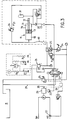
- La figure 3 est un schéma hydraulique du circuit d'alimentation énergétique et de commande du vibrateur représenté figures 1 et 2 ;
- La figure 4 est un schéma du circuit électrique associé au circuit hydraulique représenté figure 3 ;
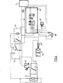
- La figure 5 est un schéma hydraulique d'une variante d'exécution du circuit d'alimentation d'un vibrateur à moment variable selon l'invention ;
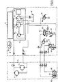
- La figure 6 est un schéma du circuit électrique associé au circuit hydraulique représenté figure 5.
- Figures 1 and 2 are two schematic sections, respectively axial and transverse, of a variable moment vibrator according to the invention;
- Figure 3 is a hydraulic diagram of the power supply circuit and control of the vibrator shown in Figures 1 and 2;
- Figure 4 is a diagram of the electrical circuit associated with the hydraulic circuit shown in Figure 3;
- Figure 5 is a hydraulic diagram of an alternative embodiment of the supply circuit of a variable-time vibrator according to the invention;
- FIG. 6 is a diagram of the electrical circuit associated with the hydraulic circuit shown in FIG. 5.
Dans l'exemple représenté sur les figures 1 et 2, le vibrateur comprend deux trains 1, 2 de masselottes excentrées montées rotatives au moyen d'arbres A₁, A₂, An - A'₁, A'₂, A'n parallèles à un axe transversal X, X' et dont les extrémités s'engagent dans des paliers portés par deux flasques parallèles 3, 4 constituant les deux côtés latéraux d'un boîtier 5.In the example shown in Figures 1 and 2, the vibrator comprises two
A chacune des masselottes M, M' est associé un pignon P disposé et dimensionné de manière à ce que les pignons P associés à un même train 1, 2 de masselottes M engrènent les uns avec les autres, par couples successifs.Each of the weights M, M ′ is associated with a pinion P arranged and dimensioned so that the pinions P associated with the
Dans cet exemple, chaque train de masselottes M comporte un couple d'ensembles masselottes M/pignon P représenté en traits pleins, l'ensemble représenté partiellement en traits interrompus indiquant le mode d'implantation d'un autre couple.In this example, each set of counterweights M comprises a pair of sets of counterweights M / pinion P shown in solid lines, the set partially represented in broken lines indicating the mode of implantation of another pair.
L'entraînement en rotation des deux trains de masselottes est assuré au moyen d'une motorisation, comportant deux moteurs hydrauliques H₁, H₂ montés sur le flasque 3 à l'une des extrémités du boîtier 5.The two flywheel trains are driven in rotation by means of a motorization, comprising two hydraulic motors H₁, H₂ mounted on the
Ces deux moteurs H₁, H₂ entraînent deux arbres respectifs parallèles passant dans des paliers solidaires des flasques 3, 4 et qui portent chacun deux pignons coaxiaux P₁, P₂ - P₅, P₆.These two motors H₁, H₂ drive two respective parallel shafts passing through bearings integral with the
Les pignons P₁ et P₆ viennent respectivement engrener avec les pignons P associés aux masselottes M' et M pour effectuer l'entraînement en rotation des trains 2 et 1.The pinions P₁ and P₆ respectively mesh with the pinions P associated with the flyweights M 'and M to carry out the rotational drive of the
Le pignon P₅ est disposé de manière à venir engrener avec un pignon P₃ solidaire de l'arbre mené 6 d'un déphaseur 7 à commande hydraulique. Ce déphaseur 7 comprend, par ailleurs, un arbre menant 8, coaxial à l'arbre mené 6, qui porte un pignon P₄ en prise avec le pignon P₂ entraîné par le moteur H₁.The pinion P₅ is arranged so as to mesh with a pinion P₃ secured to the driven
Dans l'exemple illustré figure 3, le dispositif de commande du déphaseur a été représenté schématiquement sous la forme d'un vérin hydraulique à double effet 11 dont la tige 12 qui est solidaire du piston 13 actionne un mécanisme de déphasage pouvant comprendre un train épicycloidal de Pecqueur ou même une liaison rotative comportant deux éléments rotatifs axialement mobiles l'un par rapport à l'autre. Dans ce dernier cas, l'un au moins de ces éléments comporte une gorge hélicoïdale qui coopère avec une partie de l'autre élément de manière à ce qu'un déplacement axial de l'un des deux éléments par rapport à l'autre, par exemple sous l'effet de la tige 12 engendre une rotation relative de ces deux éléments.In the example illustrated in Figure 3, the phase shifter control device has been shown schematically in the form of a double-acting hydraulic cylinder 11 whose
Le piston 13 délimite à l'intérieur du cylindre 14 du vérin 11 deux chambres, à savoir :
- une chambre de
déphasage 16 traversée par latige 12 et connectée à un circuit dedéphasage 17, - une chambre de
rephasage 18 connectée à un circuit derephasage 19.
- a
phase shift chamber 16 traversed by therod 12 and connected to aphase shift circuit 17, - a rephasing
chamber 18 connected to a rephasingcircuit 19.
La transmission entre la tige 12 du piston 13 et la commande du mécanisme de déphasage est conçue de telle manière que :
- un déplacement du
piston 13 tendant à réduire le volume de la chambre dedéphasage 16, sous l'effet d'un fluide hydraulique sous pression injecté dans la chambre derephasage 18 provoque un rephasage du déphaseur jusqu'à ce qu'en fin de course dupiston 13, les trains de masselottes se trouvent en phase et, qu'en conséquence, l'amplitude des vibrations soit maximale, et - un déplacement du
piston 13 tendant à réduire le volume de la chambre derephasage 18, sous l'effet d'un fluide hydraulique sous pression injecté dans la chambre dedéphasage 16, provoque un déphasage pouvant atteindre 180° (opposition de phase) et, en conséquence, une réduction, voire une annulation pure et simple des vibrations.
- a displacement of the
piston 13 tending to reduce the volume of thephase shift chamber 16, under the effect of a pressurized hydraulic fluid injected into therephasing chamber 18 causes a rephasing of the phase shifter until at the end of its travel of thepiston 13, the counterweight trains are in phase and, consequently, the amplitude of the vibrations is maximum, and - a displacement of the
piston 13 tending to reduce the volume of therephasing chamber 18, under the effect of a pressurized hydraulic fluid injected into the phase shifting chamber, causes a phase shift which can reach 180 ° (phase opposition) and, consequently, a reduction or even an outright cancellation of vibrations.
Le circuit de déphasage 17 qui comprend un clapet de non retour 20 est connecté à l'une S₁ des trois sorties S₁, S₂, S₃ d'un distributeur 21 dont l'entrée E est raccordée à la sortie d'une pompe hydraulique 22 entraînée par un moteur diesel 23 et dont une sortie S₃ est reliée à la bâche B par un circuit de retour à la bâche 29.The
Dans cet exemple, la pression du fluide hydraulique appliquée à l'entrée E du distributeur 21 est limitée à une valeur de sécurité par l'intermédiaire d'un circuit de retour à la bâche comprenant un pressostat 24 taré par exemple à une pression inférieure à la pression maximum admissible dans le reste du circuit de déphasage et/ou de rephasage.In this example, the pressure of the hydraulic fluid applied to the inlet E of the
De même, la sortie S₁ du distributeur 21 est reliée au circuit de retour 29 par l'intermédiaire d'un pressostat P₀₄ taré par exemple à une valeur choisie en fonction de la pression basse souhaitée dans l'accumulateur et la chambre de déphasage.Likewise, the output S₁ of the
Le moteur 23 entraîne également une deuxième pompe hydraulique P, plus puissante, destinée à alimenter les moteurs hydrauliques du vibrateur.The
Le circuit de rephasage 19 qui est connecté à une deuxième sortie S₂ du distributeur 21 comprend, en série, un distributeur 25 et un régulateur de pression 26 permettant, grâce à une commande potentiométrique 27, de faire varier la pression du fluide injecté dans la chambre de rephasage 18 dans une plage de pressions [P₁, P₂].The
Selon la commande (manuelle ou automatique) qui lui est appliquée, le distributeur 21 oriente le débit de fluide hydraulique engendré par la pompe 22 :
- soit à la bâche B par l'intermédiaire du circuit de retour à la bâche 29 (position de repos indiquée figure 4),
- soit sur le circuit de déphasage 17 en mettant le circuit de rephasage 19 en communication avec la bâche B, par l'intermédiaire du circuit 29 (position 1),
- soit sur le circuit de rephasage 19 en mettant le circuit de déphasage 17 en communication avec le circuit de retour à la bâche 29.
- either to cover B via the return circuit to cover 29 (rest position indicated in FIG. 4),
- either on the
phase shift circuit 17 by putting therephasing circuit 19 in communication with the cover B, via the circuit 29 (position 1), - either on the
rephasing circuit 19 by putting thephase shifting circuit 17 in communication with the return circuit to thecover 29.
La chambre de déphasage 16 du vérin 11 est, par ailleurs, reliée à un accumulateur hydraulique 31 dont la pression hydraulique s'accroît au fur et à mesure que le volume d'huile présent dans la chambre de déphasage 16 est transféré du vérin 11 dans l'accumulateur 31.The
Grâce à un choix judicieux des caractéristiques, volume pression de gaz, pression de chargement initiale en huile hydraulique, cet accumulateur 31 est utilisé en combinaison avec le régulateur de pression 26 pour faire en sorte qu'à chaque valeur de pression du fluide hydraulique fourni par le régulateur 26, corresponde une position du piston 13 dans le cylindre 11, et un déphasage correspondant du déphaseur.Thanks to a judicious choice of characteristics, volume of gas pressure, initial loading pressure of hydraulic oil, this
Par ailleurs, selon la commande qui lui est appliquée, le distributeur 25 assure une liaison entre le régulateur de pression 26 et la chambre de rephasage 18 ou entre cette dernière et le circuit 29 de retour à la bâche B, par l'intermédiaire d'un pressostat P₀₅ taré par exemple pour assurer le freinage approprié de l'huile évacuée de la chambre de rephasage.Furthermore, according to the command applied to it, the
Pour éviter tout risque de blocage prématuré du déphaseur par excès de pression dans l'accumulateur 31, la pression admise dans ce dernier est écrêtée à une valeur P'02 grâce à un limiteur de pression D taré à une valeur judicieusement choisie, inférieure à P₂ (valeur maximum de la pression délivrée par le régulateur). Ce limiteur D court-circuite le clapet 22 de manière à permettre, en toutes circonstances, un rephasage du déphaseur et, en conséquence, un déploiement complet du moment du vibrateur.To avoid any risk of premature blocking of the phase shifter due to excess pressure in the
Réciproquement, la chambre de rephasage 18 est mise en charge, périodiquement, par exemple à chaque arrêt du vibrateur, par l'intermédiaire d'une ligne 33 dont la pression est limitée à une valeur P'₀₁, grâce à un limiteur de pression 34 relié à la sortie du régulateur 26 et choisi à un niveau suffisamment élevé :
- i) pour fixer la pression de déphasage et permettre l'obtention de la position complètement déphasée, lorsque la chambre de rephasage 18 du vérin 11 est en communication avec le retour à la bâche (commande de rephasage au minimum), et
- ii) pour permettre à l'accumulateur 31 de développer une pression suffisante au fur et à mesure de son remplissage pour équilibrer suffisamment la pression commandée par le régulateur 26.
- i) to fix the phase shift pressure and allow the completely phase-shifted position to be obtained, when the
rephasing chamber 18 of the jack 11 is in communication with the return to the cover (minimum rephasing command), and - ii) to allow the
accumulator 31 to develop sufficient pressure as it is filled to sufficiently balance the pressure controlled by theregulator 26.
Le choix des couples de pression P'₀₁ et P'₀₂ à l'intérieur de la plage de variations P'₁ - P'₂, de l'accumulateur 31, en l'absence de limiteur de pression, assure un renouvellement de l'huile hydraulique du circuit accumulateur 31/chambre de rephasage 18, éliminant ainsi les problèmes de purge à l'occasion des successions de charge en position déphasée et de rephasage complet.The choice of the pressure couples P'₀₁ and P'₀₂ within the range of variations P'₁ - P'₂, of the
Comme précédemment mentionné, le dispositif précédemment décrit permet de résoudre d'une façon particulièrement avantageuse les phases de fonctionnement qui, jusqu'ici, étaient critiques, telles que le démarrage du moteur diesel 23, le démarrage des vibrations, l'arrêt des vibrations et le fonçage en sol dur.As previously mentioned, the device described above makes it possible to solve in a particularly advantageous manner the operating phases which, until now, were critical, such as starting the
Ainsi, le démarrage du moteur diesel 23 pourra être effectué à vide, avec les trains de masselottes en opposition de phase (moment nul).Thus, the starting of the
En outre, pour éviter d'avoir la pompe 25 en charge lors de la mise en route du moteur diesel 23, on subordonne la mise automatique en position 1 du distributeur et, en conséquence, le déphasage du déphaseur, au lancement du moteur diesel 23. A cet effet, on utilise par exemple un asservissement à la position de l'accélérateur ou encore un capteur 35 de vitesse de rotation du moteur 23 qui agit sur le distributeur 21 (liaison 36 en traits interrompus) lorsque la vitesse de rotation du moteur 23 dépasse un seuil prédéterminé. Cette disposition permet en outre de placer les trains de masselottes du vibrateur en opposition de phase et donc d'effectuer un lancement de ce vibrateur sans déclencher de vibration.In addition, to avoid having the
Pour éviter toute propagation prématurée de vibrations basse fréquence, le basculement du distributeur 21 en position 2 est subordonné électriquement à l'obtention d'un débit hydraulique minimum (en général, un débit qui correspond à la fréquence minimum de vibration) dans le circuit hydraulique principal qui alimente les moteurs hydrauliques du vibrateur. A cet effet, on peut utiliser un capteur 37 de débit placé dans le circuit hydraulique principal ou un asservissement exploitant une condition associée à la génération d'un débit suffisant par la pompe principale. Ce capteur ou cet asservissement agit sur le distributeur 21 de manière à interdire le passage en position 2 tant que le débit détecté est inférieur à un seuil prédéterminé. Eventuellement, ce capteur 37 pourra faire basculer automatiquement le distributeur en position 2 dès le franchissement du susdit seuil ou, au contraire, faire basculer automatiquement le distributeur en position 1 lorsque le débit repasse en-dessous du susdit seuil et, d'une façon plus générale, dès que les conditions de fréquence ne sont plus réunies, notamment dès que l'on commande manuellement une réduction du débit principal. Ce processus qui intervient lors de la phase d'arrêt permet d'éviter les vibrations basses fréquences qui se produisent habituellement au cours de cette phase.To avoid any premature propagation of low frequency vibrations, the tilting of the
En fait, deux méthodes peuvent être utilisées pour supprimer les nuisances dues à ces diminutions de fréquence du vibrateur associées à l'augmentation de la puissance et de la pression nécessaire au fonçage, ces méthodes consistant :
- i) à agir directement sur l'alimentation du circuit de rephasage en basculant le distributeur 21 à la position de repos ;
- ii) à déclencher le distributeur 25 de manière à mettre la chambre de rephasage 18 en communication avec le limiteur de pression P₀₅ qui est taré à une valeur de pression correspondant à la réduction d'amplitude souhaitée.
- i) acting directly on the power supply of the rephasing circuit by tilting the
distributor 21 to the rest position; - ii) triggering the
distributor 25 so as to put therephasing chamber 18 in communication with the pressure limiter P₀₅ which is set to a pressure value corresponding to the reduction in amplitude desired.
Une particularité importante du dispositif précédemment décrit consiste en ce qu'il permet d'utiliser le vibrateur en surpuissance en exploitant un phénomène de pompage habituellement considéré nuisible.An important feature of the device described above is that it allows the vibrator to be used in overpowering by exploiting a pumping phenomenon usually considered harmful.
Il s'avère, en effet, que ces transmission hydrauliques, telles que celle utilisée entre la pompe principale 25 et les moteurs hydraulique du déphaseur disposent nécessairement d'une soupape haute pression, rapidement relayée par un asservissement réduisant le débit hydraulique (réduction de l'inclinaison du plateau de la pompe hydraulique ou suppression d'un corps pour les pompes à plusieurs corps ou diversion d'une partie du débit). Ceci a pour effet non souhaitable de réduire la vitesse de rotation des moteurs hydrauliques et donc la fréquence de fonctionnement de la machine et, par conséquent, d'accroître sa nuisance vibratoire. L'asservissement du basculement du distributeur 21 de la position 2, rephasage, à la position 1, déphasage, à la mesure d'une pression juste inférieure à la pression déclenchant la réduction de débit, permet d'éviter toute perte de fréquence du vibrateur, tout en favorisant le fonçage. En effet, la perception de cette pression critique par l'asservissement conduit à réduire le moment du vibrateur, par conséquent son amplitude vibratoire, et par conséquent la puissance consommée par le vibrateur. A débit constant, ceci se traduit par la baisse de la pression hydraulique dans la transmission.It turns out, in fact, that these hydraulic transmissions, such as that used between the
Il en résulte une amélioration du rendement hydraulique de la transmission tendant à accroître légèrement la vitesse de rotation des masselottes, et par conséquent leur énergie cinétique de rotation. La perception d'une retombée de la pression au-dessous de la pression critique entraîne un basculement inverse du distributeur 21 et, par conséquent, le redéploiement du moment.This results in an improvement in the hydraulic efficiency of the transmission, which tends to slightly increase the speed of rotation of the counterweights, and consequently their kinetic energy of rotation. The perception of a drop in pressure below the critical pressure causes a reverse tilting of the
Durant cette phase transitoire, le vibrateur dispose à la fois de la puissance délivrée par la transmission hydraulique et de l'énergie cinétique accumulée dans les masselottes. Jusqu'au moment où la pression critique est de nouveau atteinte.During this transient phase, the vibrator has both the power delivered by the hydraulic transmission and the kinetic energy accumulated in the flyweights. Until the critical pressure is reached again.
On établit ainsi un régime de fonctionnement pulsatoire du vibrateur, particulièrement performant dans les sols difficiles, en évitant de descendre au-dessous des fréquences générant des ébranlements non souhaités.This establishes a pulsating operating regime of the vibrator, particularly effective in difficult soils, avoiding going below the frequencies generating undesirable disturbances.
La figure 4 montre le schéma de principe d'un circuit de commande électrique associé au circuit hydraulique précédemment décrit.Figure 4 shows the block diagram of an electrical control circuit associated with the hydraulic circuit previously described.
Ce circuit de commande est alimenté par une source de courant continu dont la borne négative 40 est reliée à la masse :
du circuit électrique 41 du régulateur de pression 26 permettant un réglage potentiométrique de la pression appliquée à la chambre de rephasage 18, et- des solénoïdes 42, 43 de commande du distributeur 21.
- the
electrical circuit 41 of thepressure regulator 26 allowing potentiometric adjustment of the pressure applied to therephasing chamber 18, and -
solenoids distributor 21.
La borne positive 46 de l'alimentation est, quant à elle, reliée :
- à l'entrée d'un dispositif de
commutation 47 associé au contact permettant le démarrage du moteurdiesel 23, au circuit électrique 41 du régulateur de pression 26,- à
un commutateur 48 actionné en fonction du débit de la pompe principale 25.
- at the input of a
switching device 47 associated with the contact enabling thediesel engine 23 to start, - to the
electrical circuit 41 of thepressure regulator 26, - to a
switch 48 actuated as a function of the flow rate of themain pump 25.
Le dispositif de commutation 47 comprend un premier interrupteur 49 en série avec un commutateur 50 dont une première sortie 51 est reliée au solénoïde 43 qui commande la position 1 du distributeur 21 et dont une deuxième sortie 52 est reliée au commutateur 48.The switching
Ce commutateur 48 actionné en fonction du débit de la pompe principale 25 comprend deux interrupteurs 53, 54 à fonctionnement alterné, à savoir :
un interrupteur 53 qui assure une liaison interruptible entre le contact du relais 44 et le solénoide 42 permettant le passage enposition 2 du distributeur 21,un interrupteur 54 permettant de relier le solénoïde 43 du distributeur 21 à la borne positive 46 de l'alimentation.
- a
switch 53 which provides an interruptible link between the contact of the relay 44 and thesolenoid 42 allowing thedistributor 21 to move toposition 2, - a
switch 54 for connecting thesolenoid 43 of thedistributor 21 to thepositive terminal 46 of the power supply.
Le fonctionnement du circuit précédemment décrit est alors le suivant :The operation of the previously described circuit is then as follows:
Lorsque le moteur diesel 23 est à l'arrêt ou tourne à une vitesse au plus égale à la vitesse de ralenti, l'interrupteur 47 et le commutateur 51 se trouvent dans la position de la figure 4 :
l'interrupteur 47 étant ouvert,- le commutateur 50 aiguillant la sortie de l'interrupteur 47 sur le solénoide 43.
- the
switch 47 being open, - the
switch 50 switching the output of theswitch 47 on thesolenoid 43.
En conséquence, le distributeur 21 est en position de repos. Il en est de même, après le démarrage, lorsque le moteur tourne au ralenti.Consequently, the
Lors du lancement du moteur 23, la détection d'une vitesse supérieure à la vitesse de ralenti provoque tout d'abord la fermeture de l'interrupteur 49 de sorte que le distributeur 21 passe en position 1 pour habiliter les trains de masselottes du vibrateur à passer en opposition de phase.When the
La détection d'un débit suffisant de la pompe principale P, suite à une commande de débit entraînant la fermeture de l'interrupteur 53, provoque ensuite le basculement du commutateur 50 sur sa sortie 51 et, en conséquence, l'excitation du solénoïde 42 du distributeur 21 qui passe en position 2 (rephasage avec déploiement du moment du vibrateur).The detection of a sufficient flow rate of the main pump P, following a flow control causing the closure of the
La détection subséquente d'un débit de la pompe principale P inférieur à une valeur de seuil provoquera alors un basculement du commutateur 48 (interrupteur 53 ouvert/interrupteur 54 fermé) et, en conséquence, le passage du distributeur 21, de la position 2 à la position 1 (déphasage avec réduction du moment).The subsequent detection of a flow rate of the main pump P less than a threshold value will then cause the
On obtient donc un processus de pompage du type de celui précédemment décrit dont l'amplitude peut être réglée par des moyens électroniques ou mécaniques agissant sur l'écart entre les valeurs de seuil de la pression du fluide hydraulique débité par la pompe hydraulique.A pumping process of the type described above is therefore obtained, the amplitude of which can be adjusted by electronic or mechanical means acting on the difference between the threshold values of the pressure of the hydraulic fluid delivered by the hydraulic pump.
Un autre avantage important du dispositif précédemment décrit consiste en ce qu'il permet d'asservir la commande d'amplitude, soit à un niveau de bruit, soit à un niveau d'amplitude vibratoire mesuré dans le sol notamment en vue de respecter les normes de bruit ou de vibration en limite de site.Another important advantage of the device described above is that it makes it possible to control the amplitude control, either at a noise level, or at a vibratory amplitude level measured in the ground in particular in order to comply with the standards. noise or vibration at the site boundary.
A cet effet, on dispose dans la zone sensible à protéger un dispositif 60 effectuant la mesure du bruit ou des vibrations. Le résultat de cette mesure est comparé à une valeur de consigne V dans un comparateur. Ce dernier agit sur le régulateur de pression, de manière à établir un déphasage approprié tendant à annuler l'écart entre la valeur mesurée et la valeur de consigne.To this end, there is in the sensitive area to be protected a
Un réseau connecteur 61, par exemple de type PID, peut être utilisé pour éviter cette fois les oscillations et pour maintenir les performances de l'appareil au maximum compatible avec les valeurs de consigne.A
Il ressort de la description qui précède que le principe de la commande de l'amplitude du moment vibratoire repose sur l'association d'une pression de commande à une position de déphasage, grâce à l'équilibre stable obtenue entre le couple moteur dû à la pression de commande d'une part, et d'autre part le couple résistant naturel du système, modifié et complété par un couple résistant connu.It appears from the foregoing description that the principle of controlling the amplitude of the vibratory moment is based on the association of a control pressure with a phase shift position, thanks to the stable balance obtained between the motor torque due to the control pressure on the one hand, and on the other hand the natural resisting torque of the system, modified and supplemented by a known resisting torque.
Pour obtenir cet équilibre, diverses méthodes peuvent être envisagées :
- Il est tout d'abord possible d'exploiter directement le seul couple de rephasage spontané engendré par le vibrateur, le couple à appliquer étant une certaine fonction de l'angle de rephasage.
- On peut également ajouter à ce couple celui engendré dans le déphaseur par une contre-pression constante, par exemple grâce à un accumulateur de grand volume de manière à limiter la contre-pression au minimum nécessaire pour obtenir le déphasage inverse à celui imposé par la commande.
- L'usage d'un accumulateur à pression de gaz, de volume par exemple égal au double ou au triple de la cylindrée du vérin déphaseur, et dont la pression varie sensiblement avec l'angle de déphasage offre une meilleure sensibilité à la pression. Cette solution, par un choix judicieux des caractéristiques de l'accumulateur, permet en outre de rendre monotone la fonction P = f (déphasage), lorsqu'elle ne l'est pas à l'origine et, en conséquence, de simplifier le mode de commande, en obtenant une valeur unique de déphasage (à une hystérésis près) pour une valeur de pression donnée et surtout d'assurer la stabilité du déphasage en fonction de la commande.
- L'usage d'un accumulateur mécanique dont la contre-pression est réalisée par un vérin à ressort permet de linéariser la courbe de contre-pression additionnelle en fonction de l'angle de déphasage.
- Il est également possible d'appliquer une contre-pression intermittente seulement en cas de besoin de mouvement inverse à celui imposé par la commande ou encore à un limiteur ou un réducteur de pression commandable par potentiomètre qui peut être commandé manuellement ou par un asservissement.
- It is first of all possible to directly exploit the only spontaneous rephasing torque generated by the vibrator, the torque to be applied being a certain function of the rephasing angle.
- One can also add to this torque that generated in the phase shifter by a constant back pressure, for example thanks to a large volume accumulator so as to limit the back pressure to the minimum necessary to obtain the reverse phase shift to that imposed by the control .
- The use of a gas pressure accumulator, of volume for example equal to twice or three times the displacement of the phase shifting cylinder, and the pressure of which varies appreciably with the phase shift angle offers better pressure sensitivity. This solution, by a judicious choice of the characteristics of the accumulator, also makes it possible to make monotonous the function P = f (phase shift), when it is not the origin and, consequently, to simplify the control mode, by obtaining a single value of phase shift (to within a hysteresis) for a given pressure value and above all to ensure the stability of the phase shift as a function of the command.
- The use of a mechanical accumulator, the back pressure of which is produced by a spring cylinder makes it possible to linearize the additional back pressure curve as a function of the phase shift angle.
- It is also possible to apply an intermittent back pressure only when the opposite movement is required to that imposed by the control or to a pressure limiter or reducer controllable by potentiometer which can be controlled manually or by a servo control.
Dans tous les cas, il sera possible d'utiliser des moyens permettant de faire varier la pression dans la chambre de déphasage et/ou la chambre de rephasage grâce à un circuit hydraulique débouchant sur différents limiteurs de pression, par l'intermédiaire de distributeurs commandés par un sélecteur.In all cases, it will be possible to use means making it possible to vary the pressure in the phase shift chamber and / or the rephasing chamber by means of a hydraulic circuit leading to different pressure limiters, by means of controlled distributors. by a selector.
Dans l'exemple représenté sur la figure 5, le vibrateur à moment variable qui a été représenté schématiquement par un bloc en traits interrompus 70 comprend deux moteurs hydrauliques 71, 72 alimentés par un générateur de fluide hydraulique sous pression 73 comprenant deux corps de pompe 74, 75 entraînés par un moteur 76, par exemple un moteur diesel. Le débit de ce générateur 73 est contrôlé par un dispositif de servocommande 77 commandé par un potentiomètre 78.In the example shown in FIG. 5, the variable moment vibrator which has been represented diagrammatically by a block in broken lines 70 comprises two
La commande du déphaseur 79 est, quant à elle, assurée par un circuit hydraulique alimenté par une pompe auxiliaire 80 entraînée par le moteur 76.The
Cette pompe auxiliaire 80 débite sur un limiteur de pression mécanique 81 qui maintient une pression Pr égale à une valeur correspondant à la pression de rephasage. La sortie de ce limiteur 81 est connectée à la chambre de rephasage 82 du déphaseur par l'intermédiaire d'un distributeur électromécanique 83 qui se trouve à l'état passant, en position de repos et qui détourne la flux d'huile vers la bâche 84 quand sa bobine 85 est excitée.This
Le fluide hydraulique délivré par la pompe auxiliaire 80 qui est, par ailleurs, contrôlé par un limiteur de pression 86 qui limite à une valeur Pmax, la pression maximale de commande, est appliqué à un second réducteur de pression à commande électrique 87, qui débite du fluide à une pression réglable entre une pression de déphasage maximum Pdmax et une pression de déphasage minimum Pdmin grâce à un circuit électronique de commande piloté par un potentiomètre 88.The hydraulic fluid delivered by the
La sortie de ce réducteur 87 est reliée à la chambre de déphasage 89 du déphaseur 79.The output of this
Au circuit hydraulique précédemment décrit est associé un circuit électrique de commande (figure 6) alimenté par une source de courant continu qui alimente, d'une part, le circuit électronique 90 du régulateur de pression permettant un réglage potentiométrique (potentiomètre 88) de la pression appliquée à la chambre de déphasage 89 ainsi que, d'autre part, l'électroaimant 85 du distributeur 83 par l'intermédiaire d'un circuit de commutation comprenant un relais 91 sur lequel est monté en parallèle un pressostat 92 qui se ferme lorsque la pression du fluide débité par les deux corps de pompe est supérieure ou égale à une pression PM.Associated with the hydraulic circuit previously described is an electrical control circuit (FIG. 6) supplied by a direct current source which supplies, on the one hand, the
Ce circuit de commande fait en outre intervenir un sélecteur rotatif 93 couplé mécaniquement au potentiomètre 78 et dont le curseur rotatif 94 balaye et commute temporairement une pluralité de contacts (ici les contacts C₁, C₂, C₃) au fur et à mesure de sa rotation.This control circuit also involves a
Dans cet exemple, le curseur 94 est relié au pôle négatif de la source d'alimentation.In this example, the
Le contact C₁ est en l'air (non relié à un quelconque circuit).Contact C₁ is in the air (not connected to any circuit).
Le contact C₂ est relié au pôle positif de l'alimentation par l'intermédiaire de la bobine KA2 d'un relais 95 qui commande l'application du pôle positif sur l'une des extrémités de la bobine KA3 du relais 91.The contact C₂ is connected to the positive pole of the power supply via the coil KA2 of a
Le contact C₃ est relié à l'autre extrémité de la bobine KA3 du relais 91.Contact C₃ is connected to the other end of coil KA3 of
Sur le plan hydraulique, le fonctionnement du dispositif précédemment décrit est le suivant :Hydraulically, the operation of the device described above is as follows:
Quelle que soit la position du potentiomètre 88 de réglage du réducteur de pression 87 (entre les pressions de déphasage minimum et maximum), lorsque la bobine 85 du distributeur 83 est excitée et que ce dernier passe de sa position de repos représentée sur la figure 5 (où elle se trouvait avant la mise en route de la machine) à sa deuxième position, le circuit de rephasage est relié à la bâche 84, et seule la chambre de déphasage 89 est alimentée (avec au moins la pression minimum de déphasage Pdmin) et, par conséquent, le vibrateur 70 n'engendre aucune amplitude vibratoire.Whatever the position of the
Par contre, lorsque la bobine 85 est désexcitée et, en conséquence, le distributeur passe au repos (après qu'une vitesse suffisante des balourds soit atteinte) alors la chambre de rephasage 82 est alimentée en fluide à la pression de rephasage (qui est légèrement inférieure à la pression de déphasage maximum) imposée par le réducteur 87.On the other hand, when the
La chambre de déphasage 82 est, quant à elle, alimentée en fluide dont la pression est comprise entre les pressions maximum et minimum de déphasage.The
Lorsque la pression de déphasage est à son maximum (par convention, position zéro du potentiomètre 88) alors le déphaseur 79 est soumis à une pression résultante de déphasage (écart entre la pression maximum de déphasage et la pression de rephasage). Du fait que le déphaseur 79 était initialement à l'état totalement déphasé et le rephasage nécessitant une pression résultante de rephasage suffisante pour vaincre les frottements et la résistance à la création de vibrations, aucune vibration n'est en mesure de s'établir.When the phase shift pressure is at its maximum (by convention, zero position of the potentiometer 88) then the
Lorsqu'ensuite on tourne le potentiomètre 88 vers les amplitudes croissantes et, qu'en conséquence, on commande une réduction de pression de déphasage du maximum vers le minimum, alors la chambre de rephasage 82 se maintient à la pression de rephasage tandis que la pression dans la chambre de déphasage 89 s'abaisse en-dessous de cette pression de rephasage. La pression résultante est donc une pression de rephasage et, en conséquence, le déphaseur se remet à rephaser les masselottes du vibrateur 70 jusqu'à ce que l'amplitude de vibration engendrée par ces dernières génère dynamiquement un couple relatif s'opposant au couple exercé par le déphaseur 79 sous l'effet de la pression résultante.When then the
Les cylindrées du déphaseur 79 et les valeurs appliquées sont choisies de manière à obtenir l'amplitude maximale utile pour un rephasage complet des deux trains de masselottes lorsque la contre-pression de déphasage atteint sa valeur minimale.The displacements of the
Le choix de la pression minimale de déphasage est celui qui permet d'assurer l'obtention d'un déphasage complet des masselottes en l'absence de pression de rephasage.The choice of the minimum phase shift pressure is that which makes it possible to obtain a complete phase shift of the flyweights in the absence of rephasing pressure.
Un limiteur de pression taré à la valeur de pression maximum de déphasage est monté sur le circuit de rephasage pour écrêter les pointes de pression constatées lorsque sous l'effet de la pression maximale de déphasage, le fluide contenu dans la chambre de rephasage 82 se trouve refoulé vers la bâche 84.A pressure limiter calibrated to the maximum phase shift pressure value is mounted on the rephasing circuit to limit the pressure peaks observed when under the effect of the maximum phase shift pressure, the fluid contained in the
Le fonctionnement du circuit électronique de commande est alors le suivant :The operation of the electronic control circuit is as follows:
Le contact C₁ du sélecteur rotatif 93 qui correspond au zéro du potentiomètre 78 et donc à un débit nul, est utilisé pour la sécurité du démarrage (interdiction de démarrer le générateur de fluide hydraulique sous pression 73 si les pompes 74, 75 ne sont pas à débit nul, pour éviter de démarrer en charge le moteur 76 et de faire tourner les masselottes lors de ce démarrage).The contact C₁ of the
En effet, lorsque le sélecteur 93 se trouve positionné sur le contact C₁, les relais 95 et 91 sont au repos, tandis que le pressostat 92 est ouvert. La bobine 85 du distributeur 83 est alimentée et ce dernier est donc au repos et renvoie à la bâche 84 le fluide débité par la pompe auxiliaire 80.When the
Le contact C₂ correspond à une position du potentiomètre 78 commandant une vitesse proche de la vitesse minimale de vibration, par exemple de 1650 tours/mn en-deçà de laquelle on souhaite interdire toute vibration dont la fréquence serait insuffisante et donc nocive.The contact C₂ corresponds to a position of the
Dans le cas où le sélecteur 93 est positionné sur ce contact C₂, le relais 95 passe à l'état excité tandis que le relais 91 demeure au repos. La bobine 85 du distributeur 83 reste donc à l'état excité.In the case where the
Le contact C₃ correspond à une position du potentiomètre 78 commandant la vitesse minimale de vibration, par exemple 1800 tours/mn.Contact C₃ corresponds to a position of
Dans cette position, le relais 95 est au repos tandis que le relais 91 passe à l'état excité (avec auto-maintien) en interrompant l'alimentation de la bobine 85 du distributeur 83, lequel commute en assurant la connexion de la sortie du limiteur 81 à la chambre de rephasage 82. Le pressostat 92 permet, quant à lui, de refermer le circuit de la bobine du distributeur, et donc de l'exciter, lorsque la pression du fluide hydraulique des deux corps de pompe 74, 75 atteint la pression maximale hydraulique admissible (cette pression est associée à la puissance maximale disponible inhérente au moteur thermique).In this position, the
Grâce à ces dispositions, au lancement du débit des corps de pompe 74, 75 qui entraîne la rotation des masselottes, pour toutes les valeurs de vitesse inférieures à la valeur minimale de vibration, la bobine 85 du distributeur 83 est excitée, ce qui interdit l'établissement de la pression de rephasage et donc de toute vibration.Thanks to these provisions, at the start of the flow of the
Lorsqu'on atteint et dépasse la vitesse minimale de vibration, la bobine 85 se trouve à l'état désexcité et l'amplitude vibratoire est établie au niveau commandé par le potentiomètre 88, déterminant la position du réducteur de pression 87.When the minimum vibration speed is reached and exceeded, the
Il est dès lors possible de régler la vitesse de rotation des masselottes (c'est-à-dire la fréquence) à n'importe quelle valeur entre la fréquence maximale et la fréquence minimale et, pour chaque valeur de fréquence minimale de vibration, de régler l'amplitude vibratoire entre zéro et l'amplitude maximale associée au moment d'excentricité maximum (masselottes tournant en phase).It is therefore possible to adjust the speed of rotation of the weights (i.e. the frequency) to any value between the maximum frequency and the minimum frequency and, for each minimum frequency value of vibration, to adjust the vibration amplitude between zero and the maximum amplitude associated with the maximum eccentricity moment (weights rotating in phase).
Dès que l'on diminue la vitesse au-dessous de la valeur jugée critique (pour la propagation des secousses dans le sol et d'ébranlements vers le porteur) par exemple 1650 tours/mn (contact C₂), alors la bobine 85 du distributeur 83 sera excitée grâce au retour de l'électroaimant 91 en position de repos. En conséquence, le distributeur 83 déclenchera la réduction et la suppression de l'amplitude vibratoire, quelle que soit la position du potentiomètre 88 de commande de l'amplitude, permettant ainsi à la machine de s'arrêter sans vibrer.As soon as the speed is lowered below the value deemed critical (for the propagation of tremors in the ground and shocks towards the carrier) for example 1650 rpm (contact C₂), then the
Lorsque le vibrateur 70 engendre des vibrations, c'est-à-dire lorsque la bobine 85 du distributeur 83 se trouve isolée du pôle négatif de l'alimentation S, du fait de l'auto-maintien du relais 91 en position excitée, et si la pression monte à la pression maximale admissible, du fait de la fermeture du pressostat 92, la bobine 85 du distributeur 83 se trouve à nouveau excitée.When the vibrator 70 generates vibrations, that is to say when the
Dans ce cas, le couple de rappel vers le déphasage des masselottes est d'autant plus important que le sol résiste et fait monter la pression engendrée par les deux corps de pompe 74, 75. Ce couple s'ajoute à la seule pression de déphasage commandée par le potentiomètre 88. Il agit sur le déphaseur 79 pour déphaser rapidement les masselottes et réduire ainsi l'amplitude du vibrateur 70 et, par conséquent, la puissance nécessaire à l'entretien de la vibration, donc la pression appelée par les moteurs hydrauliques 71, 72 du vibrateur 70.In this case, the return torque towards the phase shift of the weights is all the more important as the ground resists and causes the pressure generated by the two
Dès lors, le rendement hydraulique du générateur 73 s'améliore et la vitesse du moteur 76 s'accroît de quelques centaines de tours par minute supplémentaires. L'ensemble rotatif accumule donc de l'énergie cinétique en même temps que commute le pressostat 92 qui provoque la commutation du distributeur 83. Celui-ci rétablit l'alimentation de la pression de rephasage qui va rapidement remettre en phase les masselottes. Durant cette phase transitoire, le vibrateur 70 délivre dans le sol la puissance maximale délivrée par le générateur 73 et la puissance associée à l'excédent d'énergie cinétique de rotation des masselottes dont la vitesse de rotation décroît de quelques centaines de tours en quelques dixièmes de secondes jusqu'à ce que la pression redépasse à nouveau la pression maximale admissible. Ce phénomène de pulsation permet d'éviter au vibrateur 70 travaillant sur des sols durs de chuter significativement en fréquence (chute limitée à 10 %) contrairement aux vibrateurs traditionnels qui perdent jusqu'à 50 % de leur fréquence. Les performances de la machine s'en trouvent donc améliorées.Consequently, the hydraulic efficiency of the
Claims (27)
caractérisé en ce que les susdits moyens permettant de moduler la pression sont montés dans le circuit reliant le distributeur (21) à la chambre de déphasage (16) et comprennent un clapet de non-retour (20) et un accumulateur hydraulique (31) dont la pression de chargement est limitée grâce à un limiteur (D).Device according to claim 1,
characterized in that the above means for modulating the pressure are mounted in the circuit connecting the distributor (21) to the phase shift chamber (16) and include a non-return valve (20) and a hydraulic accumulator (31) of which the loading pressure is limited by a limiter (D).
caractérisé en ce que les moyens permettant de faire varier la pression dans la chambre de rephasage et/ou de déphasage comprennent un régulateur de pression (26) et/ou un circuit hydraulique débouchant sur différents limiteurs de pression, par l'intermédiaire de distributeurs commandés par un sélecteur.Device according to either of Claims 1 and 2,
characterized in that the means making it possible to vary the pressure in the rephasing and / or phase-shifting chamber comprise a pressure regulator (26) and / or a hydraulic circuit leading to different pressure limiters, by means of controlled distributors by a selector.
caractérisé en ce que le susdit clapet anti-retour (20) est court-circuité par un premier limiteur de pression (D) taré à une valeur inférieure à la valeur inférieure à la valeur de pression maximale de la susdite plage du susdit régulateur (26).Device according to one of claims 1 to 3,
characterized in that the aforesaid non-return valve (20) is short-circuited by a first pressure relief valve (D) set to a value less than the value less than the maximum pressure value of the above range of the above-mentioned regulator (26 ).
caractérisé en ce qu'il comprend un deuxième limiteur de pression (34) sur le circuit de déphasage, pour fixer la pression de déphasage.Device according to one of claims 1 to 4,
characterized in that it comprises a second pressure limiter (34) on the phase shift circuit, for fixing the phase shift pressure.
caractérisé en ce qu'il comprend un limiteur (34) réglable à une pression permettant le déphasage lorsque la commande de rephasage est au minimum.Device according to one of claims 1 to 4,
characterized in that it comprises a limiter (34) adjustable at a pressure allowing the phase shift when the rephasing command is at minimum.
caractérisé en ce qu'il comprend un limiteur de pression (34) permettant le chargement de l'accumulateur (31) à un niveau suffisant pour déterminer une contre-pression dont le profil, en fonction des positions de rephasage, assure la stabilité des positions de rephasage associées à la commande.Device according to one of claims 1 to 4,
characterized in that it comprises a pressure limiter (34) allowing the accumulator (31) to be charged at a level sufficient to determine a back pressure whose profile, as a function of the rephasing positions, ensures the stability of the positions rephasing associated with the command.
caractérisé en ce que les pressions de tarage des susdits premier et second distributeurs (D, 34) sont telles qu'il se produit un renouvellement de l'huile hydraulique du circuit accumulateur (31)/chambre de rephasage (18), éliminant ainsi les problèmes de purge, à l'occasion des successions de charge en position déphasée et de rephasage complet.Device according to one of the preceding claims,
characterized in that the calibration pressures of the above first and second distributors (D, 34) are such that there is a renewal of the hydraulic oil in the accumulator (31) / rephasing chamber (18) circuit, thus eliminating the bleeding problems, during load successions in phase shifted position and complete rephasing.
caractérisé en ce que les susdites masselottes (M, M' sont entraînées par au moins un actionneur hydraulique (H₁, H₂) alimenté par une pompe (P) entraînée par un moteur (23) dont la vitesse de rotation est détectée par un capteur (35), et en ce qu'il comprend des moyens permettant de mettre le susdit distributeur (21) en position de repos lors de la mise en route du moteur (23) tant que la vitesse de rotation est en-dessous d'un seuil de vitesse ou d'accélération prédéterminé.Device according to one of the preceding claims,
characterized in that the above weights (M, M 'are driven by at least one hydraulic actuator (H₁, H₂) powered by a pump (P) driven by a motor (23) whose speed of rotation is detected by a sensor ( 35), and in that it comprises means enabling the above-mentioned distributor (21) to be put in the rest position when the engine (23) is started as long as the speed of rotation is below a threshold predetermined speed or acceleration.
caractérisé en ce que les susdites masselottes sont entraînées par au moins un actionneur hydraulique alimenté par une pompe principale (P) entraînée par un moteur à explosion (23), et en ce qu'il comprend des moyens permettant de mettre le susdit distributeur (21) en position de repos lors de la mise en route du moteur (23) et tant que celui-ci est au ralenti.Device according to one of claims 1 to 7,
characterized in that the aforesaid weights are driven by at least one hydraulic actuator supplied by a main pump (P) driven by an internal combustion engine (23), and in that it comprises means making it possible to place the above-mentioned distributor (21 ) in the rest position when starting the engine (23) and as long as it is idling.
caractérisé en ce que dès le lancement du moteur (23), précédemment au ralenti, le distributeur (21) est mis en position 1 de manière à habiliter les masselottes à passer en position déphasée, immédiatement lors de la mise en rotation des masselottes (M, M').Device according to claim 10,
characterized in that as soon as the engine (23) is started, previously idling, the distributor (21) is placed in position 1 so as to enable the weights to shift into phase-shifted position, immediately during the rotation of the weights (M , M ').
caractérisé en ce que lors de la prise de vitesse de rotation des masselottes (M, M'), le distributeur (21, 85) passe en position 2 lorsque le débit de la pompe principale (P) atteint ou dépasse une valeur minimum prédéterminée.Device according to one of the preceding claims,
characterized in that when the speed of rotation of the flyweights (M, M ') is taken, the distributor (21, 85) changes to position 2 when the flow rate of the main pump (P) reaches or exceeds a predetermined minimum value.
caractérisé en ce que préalablement à la réduction de la vitesse de rotation des masselottes (M, M' ) au-dessous d'une valeur de seuil, le distributeur (21, 85) est ramené en position 1.Device according to one of the preceding claims,
characterized in that prior to the reduction of the speed of rotation of the weights (M, M ') below a threshold value, the distributor (21, 85) is returned to position 1.
caractérisé en ce que le retour en position 1 s'effectue automatiquement dès que les conditions requises de débit de la pompe (P) et donc de fréquence ne sont plus réunies.Device according to one of the preceding claims,
characterized in that the return to position 1 takes place automatically as soon as the required conditions for pump flow (P) and therefore frequency are no longer met.
caractérisé en ce qu'il comprend des moyens permettant d'effectuer une réduction de pression dans la chambre de rephasage (18, 82) lorsque la pression du fluide hydraulique débité par la pompe principale (P) s'élève au-dessus d'une première valeur, puis de provoquer le retour de la pression de rephasage à la valeur antérieure, lorsque ladite pression s'abaisse au-dessous d'une seconde valeur.Device according to one of the preceding claims,
characterized in that it comprises means allowing a reduction in pressure in the rephasing chamber (18, 82) when the pressure of the hydraulic fluid delivered by the main pump (P) rises above a first value, and then cause the rephasing pressure to return to the previous value, when said pressure drops below a second value.
caractérisé en ce que les susdites valeurs sont sensiblement égales.Device according to claim 15,
characterized in that the above values are substantially equal.
caractérisé en ce que l'écart entre les susdites valeurs est réglable par un moyen électronique ou mécanique, de manière à pouvoir régler l'amplitude du pompage.Device according to claim 15,
characterized in that the difference between the above values is adjustable by electronic or mechanical means, so as to be able to adjust the amplitude of the pumping.
caractérisé en ce que la pression délivrée par le susdit régulateur de pression (26, 88) est asservie à un niveau de bruit et/ou à un niveau d'amplitude ou de vitesse vibratoire mesurée dans le sol ou sur un ouvrage.Device according to one of the preceding claims,
characterized in that the pressure delivered by the above pressure regulator (26, 88) is controlled by a noise level and / or a level of amplitude or vibrational speed measured in the ground or on a structure.
caractérisé en ce que les nuisances dues à des diminutions de fréquence du vibrateur associées à l'augmentation de la puissance et de la pression nécessaire au fonçage sont supprimées :
characterized in that the nuisances due to decreases in frequency of the vibrator associated with the increase in power and pressure necessary for driving are eliminated:
caractérisé en ce que la pression de déclenchement de rephasage ou de diminution de déphasage est réglée de manière à permettre une sollicitation optimale de la puissance disponible délivrée par le moteur thermique ou par la transmission hydraulique.Device according to one of the preceding claims,
characterized in that the pressure for triggering the rephasing or for reducing the phase shift is adjusted so as to allow optimum demand on the available power delivered by the heat engine or by the hydraulic transmission.
caractérisé en ce que le susdit accumulateur (31) présente un grand volume de manière à limiter la contre-pression au minimum nécessaire pour obtenir le déphasage inverse à celui imposé par la commande lorsque celle-ci est ramenée à sa position associée au déphasage minimum.Device according to one of the preceding claims,
characterized in that the aforementioned accumulator (31) has a large volume so as to limit the back pressure to the minimum necessary to obtain the reverse phase shift to that imposed by the control when the latter is returned to its position associated with the minimum phase shift.
caractérisé en ce que l'accumulateur (31) présente un volume de l'ordre de une à trois fois la cylindrée du déphaseur et une pression qui, à partir dune pression minimale augmente rapidement avec l'angle de rephasage.Device according to one of claims 1 to 20,
characterized in that the accumulator (31) has a volume of the order of one to three times the displacement of the phase shifter and a pressure which, from a minimum pressure increases rapidly with the rephasing angle.
caractérisé en ce que l'accumulateur (31) est conçu de manière à fournir un profil de pression en fonction du rephasage permettant d'obtenir une stabilité de la position de rephasage.Device according to one of claims 1 to 20,
characterized in that the accumulator (31) is designed so as to provide a pressure profile as a function of the rephasing allowing to obtain a stability of the rephasing position.
caractérisé en ce qu'il comprend un accumulateur mécanique permettant de linéariser la courbe de contre-pression additionnelle en fonction de l'angle de déphasage.Device according to one of claims 1 to 20,
characterized in that it comprises a mechanical accumulator making it possible to linearize the additional backpressure curve as a function of the phase shift angle.
caractérisé en ce qu'il comprend un réducteur de pression (81) alimentant la chambre de rephasage (82) à pression sensiblement constante et un réducteur de pression (87) alimentant la chambre de déphasage (89) en pression variable entre une pression minimale et une pression maximale sensiblement équivalente à la pression de la chambre de rephasage (82).Device according to claim 1,
characterized in that it comprises a pressure reducer (81) supplying the rephasing chamber (82) at substantially constant pressure and a pressure reducer (87) supplying the phase shift chamber (89) with variable pressure between a minimum pressure and a maximum pressure substantially equivalent to the pressure of the rephasing chamber (82).
caractérisé en ce que le débit du générateur de fluide hydraulique sous pression (73) est contrôlé par un dispositif de servocommande (77) commandé par un potentiomètre (78), et en ce que la commande du susdit distributeur s'effectue au moyen d'un circuit électrique de commande comprenant un sélecteur (93) couplé mécaniquement au susdit potentiomètre.Device according to claim 25,
characterized in that the flow rate of the pressurized hydraulic fluid generator (73) is controlled by a servo-control device (77) controlled by a potentiometer (78), and in that the control of the above-mentioned distributor is carried out by means of an electrical control circuit comprising a selector (93) mechanically coupled to the above potentiometer.
caractérisé en ce que le susdit circuit de commande comprend une source de courant électrique qui alimente l'électroaimant (85) du distributeur (83), par l'intermédiaire d'un circuit de commutation comprenant un relais (91) sur lequel est monté en parallèle un pressostat (92) qui se ferme lorsque la pression du fluide débité par la pompe est supérieure ou égale à une pression maximum (PM), la bobine du susdit relais étant reliée, d'un côté, à l'un des pôles de la source de courant électrique par l'intermédiaire du sélecteur et, de l'autre coté, à l'autre pôle de la source par l'intermédiaire d'un relais commandé par ledit sélecteur.Device according to claim 26,
characterized in that the aforesaid control circuit comprises a source of electric current which feeds the electromagnet (85) of the distributor (83), via a switching circuit comprising a relay (91) on which is mounted in parallel a pressure switch (92) which closes when the pressure of the fluid delivered by the pump is greater than or equal to a maximum pressure (PM), the coil of the above relay being connected, on one side, to one of the poles of the source of electric current by means of the selector and, on the other side, to the other pole of the source by means of a relay controlled by said selector.
Applications Claiming Priority (2)
| Application Number | Priority Date | Filing Date | Title |
|---|---|---|---|
| FR9207555A FR2692523B1 (en) | 1992-06-19 | 1992-06-19 | Device for controlling a vibrator at variable time. |
| FR9207555 | 1992-06-19 |
Publications (1)
| Publication Number | Publication Date |
|---|---|
| EP0577444A1 true EP0577444A1 (en) | 1994-01-05 |
Family
ID=9430990
Family Applications (1)
| Application Number | Title | Priority Date | Filing Date |
|---|---|---|---|
| EP93401253A Withdrawn EP0577444A1 (en) | 1992-06-19 | 1993-05-14 | Control device of a vibrator with variable imbalance |
Country Status (4)
| Country | Link |
|---|---|
| US (1) | US5410879A (en) |
| EP (1) | EP0577444A1 (en) |
| CA (1) | CA2097450A1 (en) |
| FR (1) | FR2692523B1 (en) |
Cited By (5)
| Publication number | Priority date | Publication date | Assignee | Title |
|---|---|---|---|---|
| WO1996003224A1 (en) * | 1994-07-21 | 1996-02-08 | GEDIB Ingenieurbüro und Innovationsberatung GmbH | Compensation for transverse vibrations in unbalanced mass vibrators |
| DE19631991A1 (en) * | 1996-08-08 | 1998-03-12 | Abi Maschinenfabrik Und Vertri | Vibrator ram for underground construction |
| FR2918473A1 (en) * | 2007-07-03 | 2009-01-09 | Ptc Sa | HYDRAULIC POWER SUPPLY SYSTEM SUPPLYING HYDRAULIC FLUID TO A VIBRATOR. |
| EP2085149A1 (en) * | 2008-01-29 | 2009-08-05 | ABI Anlagentechnik-Baumaschinen-Industriebedarf Maschinenfabrik und Vertriebsgesellschaft mbH | Vibrator for a vibratory pile driver |
| EP2085148A1 (en) * | 2008-01-29 | 2009-08-05 | ABI Anlagentechnik-Baumaschinen-Industriebedarf Maschinenfabrik und Vertriebsgesellschaft mbH | Vibrator for a vibratory pile driver |
Families Citing this family (31)
| Publication number | Priority date | Publication date | Assignee | Title |
|---|---|---|---|---|
| FR2772805B1 (en) * | 1997-12-24 | 2000-02-25 | Procedes Tech Const | DEVICE FOR CONTROLLING THE AMPLITUDE OF THE VIBRATIONS OF A VARIABLE MOMENT |
| US6227760B1 (en) * | 1998-02-06 | 2001-05-08 | Mikasa Sangyo Co., Ltd. | Travel control device for vibrating plate compactor |
| DE10121383C2 (en) * | 2001-05-02 | 2003-04-03 | Wacker Werke Kg | Control for an unbalance adjustment device in a vibration exciter of a soil compacting device |
| US6981558B2 (en) * | 2001-05-02 | 2006-01-03 | Wacker Construction Equipment Ag | Controller for an unbalanced mass adjusting unit of a soil compacting device |
| US6769838B2 (en) | 2001-10-31 | 2004-08-03 | Caterpillar Paving Products Inc | Variable vibratory mechanism |
| US7694747B1 (en) | 2002-09-17 | 2010-04-13 | American Piledriving Equipment, Inc. | Preloaded drop hammer for driving piles |
| US7168890B1 (en) * | 2004-01-20 | 2007-01-30 | American Piledriving Equipment, Inc. | Eccentric vibration system with resonance control |
| US8267652B2 (en) * | 2004-08-30 | 2012-09-18 | Lord Corporation | Helicopter hub mounted vibration control and circular force generation systems for canceling vibrations |
| US8162606B2 (en) | 2004-08-30 | 2012-04-24 | Lord Corporation | Helicopter hub mounted vibration control and circular force generation systems for canceling vibrations |
| US7722322B2 (en) * | 2004-08-30 | 2010-05-25 | Lord Corporation | Computer system and program product for controlling vibrations |
| CN101022994B (en) | 2004-08-30 | 2012-07-04 | 洛德公司 | Helicopter vibration control system and rotary force generator for canceling vibrations |
| DE102005029433A1 (en) * | 2005-06-24 | 2006-12-28 | Wacker Construction Equipment Ag | Vibrating plate for compacting soil has one unbalanced mass not requiring phase adjusting device but all other unbalanced masses with such device |
| US7854571B1 (en) | 2005-07-20 | 2010-12-21 | American Piledriving Equipment, Inc. | Systems and methods for handling piles |
| EP2002129A4 (en) * | 2006-03-13 | 2011-08-03 | Volvo Constr Equip Ab | Arrangement and method for delivering hydraulic fluid in a work vehicle |
| WO2009055007A2 (en) | 2007-10-25 | 2009-04-30 | Lord Corporation | Distributed active vibration control systems and rotary wing aircraft with suppressed vibrations |
| EP2067533B2 (en) * | 2007-12-06 | 2016-12-07 | ABI Anlagentechnik-Baumaschinen-Industriebedarf Maschinenfabrik und Vertriebsgesellschaft mbH | Vibrator for a vibratory pile driver |
| EP2105213B1 (en) * | 2008-03-28 | 2018-01-24 | ABI Anlagentechnik-Baumaschinen-Industriebedarf Maschinenfabrik und Vertriebsgesellschaft mbH | Vibration creator |
| EP2105214B1 (en) * | 2008-03-28 | 2018-09-12 | ABI Anlagentechnik-Baumaschinen-Industriebedarf Maschinenfabrik und Vertriebsgesellschaft mbH | Vibration creator |
| EP2158976B1 (en) * | 2008-08-27 | 2013-08-14 | ABI Anlagentechnik-Baumaschinen-Industriebedarf Maschinenfabrik und Vertriebsgesellschaft mbH | Vibration creator |
| US20110110725A1 (en) * | 2009-11-06 | 2011-05-12 | International Construction Equipment, Inc. | Vibratory pile driving apparatus |
| US8763719B2 (en) | 2010-01-06 | 2014-07-01 | American Piledriving Equipment, Inc. | Pile driving systems and methods employing preloaded drop hammer |
| US8434969B2 (en) | 2010-04-02 | 2013-05-07 | American Piledriving Equipment, Inc. | Internal pipe clamp |
| US20120053450A1 (en) * | 2010-05-10 | 2012-03-01 | Septimiu Salcudean | Trans-perineal prostate MR elastography |
| EP2789402B1 (en) * | 2013-04-10 | 2017-05-17 | ABI Anlagentechnik-Baumaschinen-Industriebedarf Maschinenfabrik und Vertriebsgesellschaft mbH | Oscillation exciter |
| US10364865B2 (en) * | 2013-08-29 | 2019-07-30 | Lord Corporation | Circular force generator (CFG) devices, systems, and methods having indirectly driven imbalanced rotors |
| US10669677B2 (en) | 2013-12-16 | 2020-06-02 | Volvo Construction Equipment Ab | Hydraulic system for driving a vibratory mechanism |
| US10392871B2 (en) | 2015-11-18 | 2019-08-27 | American Piledriving Equipment, Inc. | Earth boring systems and methods with integral debris removal |
| US9957684B2 (en) | 2015-12-11 | 2018-05-01 | American Piledriving Equipment, Inc. | Systems and methods for installing pile structures in permafrost |
| US10273646B2 (en) | 2015-12-14 | 2019-04-30 | American Piledriving Equipment, Inc. | Guide systems and methods for diesel hammers |
| US10538892B2 (en) | 2016-06-30 | 2020-01-21 | American Piledriving Equipment, Inc. | Hydraulic impact hammer systems and methods |
| US10889944B2 (en) * | 2018-08-28 | 2021-01-12 | Caterpillar Paving Products Inc. | Control system for controlling operation of compaction systems of a paving machine |
Citations (3)
| Publication number | Priority date | Publication date | Assignee | Title |
|---|---|---|---|---|
| FR1566358A (en) * | 1968-02-09 | 1969-05-09 | ||
| WO1989007988A1 (en) * | 1988-03-03 | 1989-09-08 | Firma Wacker-Werke Gmbh & Co. Kg | Vibrator |
| EP0524056A1 (en) * | 1991-07-15 | 1993-01-20 | Procedes Techniques De Construction | Vibrator with variable imbalance, particularly for driving objects into the ground |
Family Cites Families (4)
| Publication number | Priority date | Publication date | Assignee | Title |
|---|---|---|---|---|
| US3004389A (en) * | 1959-04-25 | 1961-10-17 | Muller Ludwig | Device for varying the frequency of a vibration exciter |
| SE453000B (en) * | 1986-06-27 | 1988-01-04 | Dynapac Ab | Vibration Plate |
| FR2664831B1 (en) * | 1990-07-20 | 1993-06-11 | Procedes Tech Con | MULTI-FREQUENCY VIBRATOR. |
| US5177386A (en) * | 1990-08-30 | 1993-01-05 | Kencho Kobe Co., Ltd. | Vibration generator adjustable during operation |
-
1992
- 1992-06-19 FR FR9207555A patent/FR2692523B1/en not_active Expired - Fee Related
-
1993
- 1993-05-14 EP EP93401253A patent/EP0577444A1/en not_active Withdrawn
- 1993-06-01 CA CA002097450A patent/CA2097450A1/en not_active Abandoned
- 1993-06-04 US US08/071,635 patent/US5410879A/en not_active Expired - Fee Related
Patent Citations (3)
| Publication number | Priority date | Publication date | Assignee | Title |
|---|---|---|---|---|
| FR1566358A (en) * | 1968-02-09 | 1969-05-09 | ||
| WO1989007988A1 (en) * | 1988-03-03 | 1989-09-08 | Firma Wacker-Werke Gmbh & Co. Kg | Vibrator |
| EP0524056A1 (en) * | 1991-07-15 | 1993-01-20 | Procedes Techniques De Construction | Vibrator with variable imbalance, particularly for driving objects into the ground |
Cited By (9)
| Publication number | Priority date | Publication date | Assignee | Title |
|---|---|---|---|---|
| WO1996003224A1 (en) * | 1994-07-21 | 1996-02-08 | GEDIB Ingenieurbüro und Innovationsberatung GmbH | Compensation for transverse vibrations in unbalanced mass vibrators |
| DE19631991A1 (en) * | 1996-08-08 | 1998-03-12 | Abi Maschinenfabrik Und Vertri | Vibrator ram for underground construction |
| DE19631991B4 (en) * | 1996-08-08 | 2005-02-24 | Abi Maschinenfabrik Und Vertriebsgesellschaft Mbh | Vibrator, especially for a vibration bear |
| FR2918473A1 (en) * | 2007-07-03 | 2009-01-09 | Ptc Sa | HYDRAULIC POWER SUPPLY SYSTEM SUPPLYING HYDRAULIC FLUID TO A VIBRATOR. |
| EP2014835A1 (en) * | 2007-07-03 | 2009-01-14 | Ptc | System controlling a hydraulic group supplying a vibrator with hydraulic fluid |
| EP2085149A1 (en) * | 2008-01-29 | 2009-08-05 | ABI Anlagentechnik-Baumaschinen-Industriebedarf Maschinenfabrik und Vertriebsgesellschaft mbH | Vibrator for a vibratory pile driver |
| EP2085148A1 (en) * | 2008-01-29 | 2009-08-05 | ABI Anlagentechnik-Baumaschinen-Industriebedarf Maschinenfabrik und Vertriebsgesellschaft mbH | Vibrator for a vibratory pile driver |
| US7870910B2 (en) | 2008-01-29 | 2011-01-18 | Abi Anlagentechnik-Baumaschinen-Industriebedarf Maschinenfabrik Und Vertriebsgesellschaft Mbh | Vibration generator for a vibration pile driver |
| US8522891B2 (en) | 2008-01-29 | 2013-09-03 | ABI Anlangentechnik-Baumaschinen-Industriebedarf Maschinenfabrik und Vertriebsgesellschaft mbH | Vibration generator for a vibration pile driver |
Also Published As
| Publication number | Publication date |
|---|---|
| US5410879A (en) | 1995-05-02 |
| FR2692523B1 (en) | 1994-10-07 |
| FR2692523A1 (en) | 1993-12-24 |
| CA2097450A1 (en) | 1993-12-20 |
Similar Documents
| Publication | Publication Date | Title |
|---|---|---|
| EP0577444A1 (en) | Control device of a vibrator with variable imbalance | |
| EP0414782B1 (en) | Gear box with continuously variable gear | |
| EP0045472B1 (en) | Hydraulic power generator driven by a free piston engine | |
| FR2761409A1 (en) | METHOD AND DEVICE FOR CONTROLLING AN INTERNAL COMBUSTION ENGINE | |
| WO2007045785A1 (en) | Method for starting a hybrid vehicle heat engine | |
| FR2811943A1 (en) | Method of reducing vibration in motor vehicle transmission involves producing short term reverse couple at commencement of vibration | |
| FR2791749A1 (en) | METHOD AND DEVICE FOR DETERMINING THE ATTACK POINT OF AN ASSISTED CLUTCH | |
| FR3049540A1 (en) | VEHICLE CONTROL APPARATUS AND VEHICLE CONTROL METHOD | |
| FR3040078A1 (en) | METHOD FOR STARTING A VEHICLE INTERNAL COMBUSTION ENGINE | |
| FR2764559A1 (en) | DRIVE SYSTEM FOR MOTOR VEHICLE | |
| EP2445741B1 (en) | Method and device for starting the engine of a vehicle | |
| EP0044834A1 (en) | Propulsion unit for motor vehicle using a thermal engine down to low working speeds with the assistance of an electric machine. | |
| FR2507837A1 (en) | ENERGY TRANSMISSION SYSTEM FOR BATTERY-POWERED ELECTRIC VEHICLES | |
| WO2008037893A2 (en) | Device for converting a linear movement into a rotational movement in an adjustable manner | |
| WO2013083885A1 (en) | Transmission device, power train, energy accumulator, and vehicle equipped therewith | |
| BE894478Q (en) | STEERING WHEEL ASSEMBLY, IN PARTICULAR FOR MOTOR VEHICLES | |
| FR2928418A1 (en) | DEVICE AND METHOD FOR CONTROLLING THE AIR RESERVE IN PILOT INTERNAL COMBUSTION ENGINES BASED ON ROTATION SPEED | |
| EP1041278B1 (en) | Vehicle starter control device to produce less starter wear | |
| WO2023214127A1 (en) | Improved hydraulic system for vibration generation | |
| FR2803631A1 (en) | Method of starting motor vehicle internal combustion engine involves detecting given operating parameter and controlling starter depending on pre-selected modes of engine operation | |
| BE358037A (en) | ||
| FR1449708A (en) | Free-piston engine machine | |
| FR2983547A1 (en) | Kinetic energy accumulator for e.g. recovering deceleration energy, in continuously variable and energy storage device of car, has lateral surface comprising conformations for setting rotation of gas in same direction as that of wheel | |
| FR3065259A1 (en) | USE OF AN ELECTRIC MACHINE IN STARTER MODE TO ASSIST THE RUNNING OF THE MOTOR OF A MOTORCYCLE FOLLOWING A STOPPING TYPE "STOP & GO" | |
| WO2005091491A1 (en) | Energy storage electricity generating device |
Legal Events
| Date | Code | Title | Description |
|---|---|---|---|
| PUAI | Public reference made under article 153(3) epc to a published international application that has entered the european phase |
Free format text: ORIGINAL CODE: 0009012 |
|
| 17P | Request for examination filed |
Effective date: 19930601 |
|
| AK | Designated contracting states |
Kind code of ref document: A1 Designated state(s): BE CH DE ES FR GB IT LI NL |
|
| 17Q | First examination report despatched |
Effective date: 19940616 |
|
| STAA | Information on the status of an ep patent application or granted ep patent |
Free format text: STATUS: THE APPLICATION IS DEEMED TO BE WITHDRAWN |
|
| 18D | Application deemed to be withdrawn |
Effective date: 19950628 |