EP2067533B2 - Vibrator for a vibratory pile driver - Google Patents
Vibrator for a vibratory pile driver Download PDFInfo
- Publication number
- EP2067533B2 EP2067533B2 EP08000543.2A EP08000543A EP2067533B2 EP 2067533 B2 EP2067533 B2 EP 2067533B2 EP 08000543 A EP08000543 A EP 08000543A EP 2067533 B2 EP2067533 B2 EP 2067533B2
- Authority
- EP
- European Patent Office
- Prior art keywords
- vibrator
- sensors
- module
- accordance
- unbalanced masses
- Prior art date
- Legal status (The legal status is an assumption and is not a legal conclusion. Google has not performed a legal analysis and makes no representation as to the accuracy of the status listed.)
- Active
Links
- 230000001133 acceleration Effects 0.000 claims description 17
- 230000003068 static effect Effects 0.000 claims description 12
- 230000001939 inductive effect Effects 0.000 claims description 6
- 239000000463 material Substances 0.000 claims description 4
- 230000000007 visual effect Effects 0.000 claims description 3
- 230000001105 regulatory effect Effects 0.000 claims 1
- 238000011156 evaluation Methods 0.000 description 5
- 230000001965 increasing effect Effects 0.000 description 3
- 238000010276 construction Methods 0.000 description 2
- 238000001514 detection method Methods 0.000 description 2
- 239000002689 soil Substances 0.000 description 2
- 230000008878 coupling Effects 0.000 description 1
- 238000010168 coupling process Methods 0.000 description 1
- 238000005859 coupling reaction Methods 0.000 description 1
- 238000011161 development Methods 0.000 description 1
- 230000018109 developmental process Effects 0.000 description 1
- 230000005484 gravity Effects 0.000 description 1
- 238000009434 installation Methods 0.000 description 1
- 239000007788 liquid Substances 0.000 description 1
- 230000003287 optical effect Effects 0.000 description 1
Images
Classifications
-
- B—PERFORMING OPERATIONS; TRANSPORTING
- B06—GENERATING OR TRANSMITTING MECHANICAL VIBRATIONS IN GENERAL
- B06B—METHODS OR APPARATUS FOR GENERATING OR TRANSMITTING MECHANICAL VIBRATIONS OF INFRASONIC, SONIC, OR ULTRASONIC FREQUENCY, e.g. FOR PERFORMING MECHANICAL WORK IN GENERAL
- B06B1/00—Methods or apparatus for generating mechanical vibrations of infrasonic, sonic, or ultrasonic frequency
- B06B1/10—Methods or apparatus for generating mechanical vibrations of infrasonic, sonic, or ultrasonic frequency making use of mechanical energy
- B06B1/16—Methods or apparatus for generating mechanical vibrations of infrasonic, sonic, or ultrasonic frequency making use of mechanical energy operating with systems involving rotary unbalanced masses
- B06B1/161—Adjustable systems, i.e. where amplitude or direction of frequency of vibration can be varied
- B06B1/166—Where the phase-angle of masses mounted on counter-rotating shafts can be varied, e.g. variation of the vibration phase
-
- E—FIXED CONSTRUCTIONS
- E02—HYDRAULIC ENGINEERING; FOUNDATIONS; SOIL SHIFTING
- E02D—FOUNDATIONS; EXCAVATIONS; EMBANKMENTS; UNDERGROUND OR UNDERWATER STRUCTURES
- E02D7/00—Methods or apparatus for placing sheet pile bulkheads, piles, mouldpipes, or other moulds
- E02D7/18—Placing by vibrating
Definitions
- the invention relates to a vibration generator according to the preamble of claim 1.
- the invention further relates to a vibratory pile driver according to claim 6.
- vibrators are used to bring objects such as profiles into the ground or to pull them out of the ground or to compact soil material.
- the soil is stimulated by vibration and thus reaches a "pseudo-liquid" state.
- the vibration is characterized by a linear movement and is generated by pairwise counter-rotating imbalances within a Vibratorgetriebes.
- Vibration generators are characterized by the rotating unbalance and the maximum speed. Such a vibration generator is eg in EP 0 926 300 A1 disclosed.
- the vibration generators are linear vibration exciters whose centrifugal force is generated by rotating imbalances. These vibration exciters move at a variable speed.
- the size of the imbalance is also called "static moment".
- the course of the velocity of the linear vibration exciter corresponds to a periodically recurring function, for example a sine function, but it can also take other forms. For a sinusoidal course of the velocity, the following applies: If the unbalance center of gravity is in the direction of movement or perpendicular thereto, the angular acceleration of the imbalances and all the associated rotating parts is 0. Maximum values of the angular acceleration occur when the imbalances relative to the direction of movement are approximately 45, 135, 225 or 315 degrees are deflected.
- the invention aims to remedy this situation.
- the invention is based on the object to provide a vibration exciter, which allows a reduction in the indexed by changing vibration speeds loads of machine elements in operation. According to the invention, this object is solved by the features of the characterizing part of patent claim 1.
- a vibration exciter is created, which allows a reduction in the indicated by changing vibration speeds loads of machine elements in operation.
- sensors for detecting the relative position of the imbalance masses to each other and for detecting the acceleration of the vibrator.
- the sensors preferably include inductive sensors, acceleration sensors and / or rotary encoders. Such sensors have proven to be durable and robust.
- the sensors are connected to an evaluation unit, which compares the measured values recorded by the sensors with stored maximum values. This allows the detection of load peaks.
- the evaluation unit preferably determines the currently applied static torque on the basis of the measured values determined by the sensors.
- the evaluation unit is connected to an audible and / or visual warning device.
- a device for controlling the vibration generator is arranged, which is connected to the evaluation unit. In this way, automatic regulation of the vibration generator as a function of the detected measured values of the vibration generator is made possible.
- the means for changing the relative rotational position of the rotatable imbalance masses to each other via the control device can be controlled. This allows a direct control of the static torque of the vibrator.
- the evaluation unit advantageously has a programmable logic controller (PLC). This allows flexible control of the vibration generator.
- PLC programmable logic controller
- the invention is further based on the object to provide a Vibratoryramm réelle that allows a reduction in the indicated by changing vibration speeds of the vibrator loads of machine elements in operation. According to the invention, this object is solved by the features of patent claim 6.
- a vibratory pile driver is provided, which allows a reduction in the indicated by changing vibration velocities of the vibrator loads of machine elements in operation.
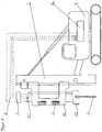
- the vibration ramming device chosen as an exemplary embodiment consists essentially of a carrier device 1, on which a vibrator (vibrator) 3 is arranged so as to be vertically displaceable via a broker 2.
- the vibration generator 3 comprises a housing 31, which is surrounded by a hood 30. On the hood 30, a clamping tongs 37 for receiving pile material 4 is arranged.
- the hood 30 serves to guide the vibrator 3 and transmits the static force of the leader 2 to the vibrator 3.
- the vibrator 3 generates via rotating imbalances 3311, 3321, 3331, 3511, 3521, 3531, a vibration which via the clamping forceps 33 on the Rammgut 4 is transmitted.
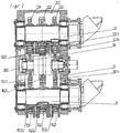
- the vibrator 3 is designed as a vibrator gearbox ( FIG. 2 ). It consists essentially of a housing 31 in which gears 331, 332, 333, 351, 352, 353 provided with shafts 33, 35 are rotatably mounted.
- the gears 331, 332, 333, 351, 352, 353 are each provided with unbalanced masses 3311, 3321, 3331, 3511, 3521, 3531, wherein the gears of both shafts 3, 5 via gears 3613, 3614 of the rotor shaft 361 of a pivot motor 36 with each other are engaged.
- the gears 331, 3321, 3331, 3511, 3521, 3531 provided with unbalanced masses 331, 332, 333, 351, 352, 353 are adjustable relative to each other via the pivot motor 36 in its rotational position, whereby the resulting imbalance or the resulting static moment is adjustable.
- Such Vibratorgetriebe with rotatably mounted imbalance masses that are adjustable in relative phase position the skilled person for example from the DE 20 2007 005 283 U1 known.
- the vibrator 3 is opposite to the gears 331, 332, 333, 351, 352, 353 provided on the inside of the housing 31 each with two parallel to the circumference of the gears spaced from each other arranged inductive sensors 310.
- the inductive sensors 310 enable the detection of the angular acceleration of the rotating imbalance masses 3311, 3321, 3331, 3511, 3521, 3531.
- the time offset of the imbalance masses 3311, 3321, 3331, 3511, 3521, 3531 can furthermore be used to determine their relative position to one another.
- an acceleration sensor 311 is arranged on the housing 31 of the vibration generator 3.
- a programmable logic controller (PLC) 7 is arranged, which further calculated on the basis of frequency and time offset of the imbalance masses to each other applied static moment.
- PLC programmable logic controller
- a controller 8 is arranged, which is connected via lines 6 to the PLC 7.
- the controller 8 is set up in such a way that it calculates an admissible angular acceleration of the rotating parts of the vibration generator 3 from the static torque determined by the SPS 7 and the known moment of inertia of the rotating parts and the acceleration data determined by the sensor 311.
- the installation of an optical and / or acoustic signal in the operator's stand of the carrier device is possible in order to inform the operator of exceeding permissible acceleration values.
- the adjustment of the resulting imbalance / the resulting static torque can be done in this case on the operator by appropriate control of the swing motor within the vibrator 3.
Description
Die Erfindung betrifft einen Schwingungserzeuger nach dem Oberbegriff des Patentanspruchs 1. Die Erfindung betrifft weiterhin ein Vibrationsrammgerät nach dem Patentanspruch 6.The invention relates to a vibration generator according to the preamble of claim 1. The invention further relates to a vibratory pile driver according to claim 6.
Im Bauwesen werden Schwingungserzeuger verwendet, um Objekte, wie beispielsweise Profile, in den Boden einzubringen oder aus dem Boden zu ziehen oder auch um Bodenmaterial zu verdichten. Der Boden wird durch Vibration angeregt und erreicht so einen "pseudoflüssigen" Zustand. Durch statische Auflast kann das Rammgut dann in den Baugrund gedrückt werden. Die Vibration ist gekennzeichnet durch eine lineare Bewegung und wird durch paarweise gegenläufig rotierende Unwuchten innerhalb eines Vibratorgetriebes generiert. Schwingungserzeuger werden charakterisiert durch die rotierende Unwucht und die maximale Drehzahl. Ein solcher Schwingungserzeuger ist z.B. in
Die Schwingungserzeuger sind linear wirkende Schwingungserreger, deren Fliehkraft durch rotierende Unwuchten generiert wird. Diese Schwingungserreger bewegen sich mit veränderlicher Geschwindigkeit. Die Größe der Unwucht wird auch als "statisches Moment" bezeichnet. Der Verlauf der Geschwindigkeit des linearen Schwingungserregers entspricht einer periodisch wiederkehrenden Funktion, beispielsweise einer Sinusfunktion, sie kann aber auch andere Formen einnehmen. Für einen sinusförmigen Verlauf der Geschwindigkeit gilt: Liegt der Unwuchtschwerpunkt in Bewegungsrichtung oder senkrecht dazu, ist die Winkelbeschleunigung der Unwuchten und aller damit verbundenen rotierenden Teile 0. Maximalwerte der Winkelbeschleunigung treten auf, wenn die Unwuchten gegenüber der Bewegungsrichtung ca. 45, 135, 225 oder 315 Grad ausgelenkt sind.The vibration generators are linear vibration exciters whose centrifugal force is generated by rotating imbalances. These vibration exciters move at a variable speed. The size of the imbalance is also called "static moment". The course of the velocity of the linear vibration exciter corresponds to a periodically recurring function, for example a sine function, but it can also take other forms. For a sinusoidal course of the velocity, the following applies: If the unbalance center of gravity is in the direction of movement or perpendicular thereto, the angular acceleration of the imbalances and all the associated rotating parts is 0. Maximum values of the angular acceleration occur when the imbalances relative to the direction of movement are approximately 45, 135, 225 or 315 degrees are deflected.
Durch die wechselnde Schwinggeschwindigkeit ist eine Veränderung der kinetischen Energie des Gehäuses des Schwingungserzeugers bewirkt, welche als Blindleistung übertragen und von den innerhalb des Schwingungserzeugers rotierenden Teilen, insbesondere Wellen, Unwuchten und Zahnrädern periodisch aufgenommen, gespeichert und wieder abgegeben wird. Die wechselnden Winkelbeschleunigungen bewirken eine erhöhte Belastung von Maschinenelementen, wie Lagern oder Kupplungen. Diese Problematik wird durch leistungssteigernde Maßnahmen des Schwingungserzeugers, wie Leichtbauweise, Vergrößerung des statischen Moments (der Unwucht) oder Erhöhung der Drehzahl weiter verschärft.Due to the changing vibration speed, a change in the kinetic energy of the housing of the vibrator is effected, which is transmitted as reactive power and periodically recorded by the rotating within the vibrator parts, in particular waves, imbalances and gears, stored and discharged again. The changing angular accelerations cause an increased load of machine elements, such as bearings or couplings. This problem is exacerbated by performance-enhancing measures of the vibrator, such as lightweight construction, increasing the static torque (imbalance) or increasing the speed.
Hier will die Erfindung Abhilfe schaffen. Der Erfindung liegt die Aufgabe zu Grunde, einen Schwingungserreger zu schaffen, der eine Reduzierung der durch wechselnde Schwinggeschwindigkeiten indizierten Belastungen von Maschinenelementen im Betrieb ermöglicht. Gemäß der Erfindung wird diese Aufgabe durch die Merkmale des kennzeichnenden Teils des Patentanspruchs 1 gelöst.The invention aims to remedy this situation. The invention is based on the object to provide a vibration exciter, which allows a reduction in the indexed by changing vibration speeds loads of machine elements in operation. According to the invention, this object is solved by the features of the characterizing part of patent claim 1.
Mit der Erfindung ist ein Schwingungserreger geschaffen, der eine Reduzierung der durch wechselnde Schwinggeschwindigkeiten indizierten Belastungen von Maschinenelementen im Betrieb ermöglicht. Es sind Sensoren zur Erfassung der relativen Position der Unwuchtmassen zueinander sowie zur Erfassung der Beschleunigung des Schwingungserzeugers vorgesehen. Mit Hilfe der hiermit ermittelten Messwerte ist unter Zuhilfenahme der bekannten Größen Massenträgheit und Massenträgheitsmoment des Schwingungserzeugers eine entsprechende Ermittlung der jeweils anliegenden Winkelbeschleunigung der rotierenden Unwuchtmassen ermöglicht.With the invention, a vibration exciter is created, which allows a reduction in the indicated by changing vibration speeds loads of machine elements in operation. There are provided sensors for detecting the relative position of the imbalance masses to each other and for detecting the acceleration of the vibrator. With the aid of the measured values ascertained with the aid of the known variables of mass inertia and mass moment of inertia of the vibration generator, a corresponding determination of the respective adjacent angular acceleration of the rotating imbalance masses is made possible.
Bevorzugt umfassen die Sensoren induktive Sensoren, Beschleunigungssensoren und/oder Drehgeber. Derartige Sensoren haben sich als langlebig und robust erwiesen.The sensors preferably include inductive sensors, acceleration sensors and / or rotary encoders. Such sensors have proven to be durable and robust.
In der Erfindung sind die Sensoren mit einer Auswerteeinheit verbunden, welche die von den Sensoren erfassten Messwerte mit hinterlegten Maximalwerten vergleicht. Hierdurch ist die Detektierung von Belastungsspitzen ermöglicht. Bevorzugt ermittelt die Auswerteeinheit auf Basis der von den Sensoren ermittelten Messwerte das jeweils anliegende statische Moment.In the invention, the sensors are connected to an evaluation unit, which compares the measured values recorded by the sensors with stored maximum values. This allows the detection of load peaks. The evaluation unit preferably determines the currently applied static torque on the basis of the measured values determined by the sensors.
In Ausgestaltung der Erfindung ist die Auswerteeinheit mit einer akustischen und /oder visuellen Warneinrichtung verbunden. Hierdurch ist die akustische bzw. visuelle Information des Bedieners über einen kritischen Zustand ermöglicht. Bevorzugt ist eine Einrichtung zur Regelung des Schwingungserzeugers angeordnet, welche mit der Auswerteeinheit verbunden ist. Hierdurch ist eine automatische Regelung des Schwingungserzeugers in Abhängigkeit von den erfassten Messwerten des Schwingungserzeugers ermöglicht.In an embodiment of the invention, the evaluation unit is connected to an audible and / or visual warning device. As a result, the acoustic or visual information of the operator about a critical state is possible. Preferably, a device for controlling the vibration generator is arranged, which is connected to the evaluation unit. In this way, automatic regulation of the vibration generator as a function of the detected measured values of the vibration generator is made possible.
In Ausgestaltung der Erfindung sind die Mittel zur Änderung der relativen Drehposition der rotierbaren Unwuchtmassen zueinander über die Regeleinrichtung ansteuerbar. Hierdurch ist eine direkte Regelung des statischen Moments des Schwingungserzeugers ermöglicht.In an embodiment of the invention, the means for changing the relative rotational position of the rotatable imbalance masses to each other via the control device can be controlled. This allows a direct control of the static torque of the vibrator.
Vorteilhaft weist die Auswerteeinheit eine speicherprogrammierbare Steuerung (SPS) auf. Hierdurch ist eine flexible Steuerung des Schwingungserzeugers ermöglicht.The evaluation unit advantageously has a programmable logic controller (PLC). This allows flexible control of the vibration generator.
Der Erfindung liegt weiterhin die Aufgabe zu Grunde, ein Vibrationsrammgerät zu schaffen, das eine Reduzierung der durch wechselnde Schwinggeschwindigkeiten des Schwingungserzeugers indizierten Belastungen von Maschinenelementen im Betrieb ermöglicht. Gemäß der Erfindung wird diese Aufgabe durch die Merkmale des Patentanspruchs 6 gelöst.The invention is further based on the object to provide a Vibratoryrammgerät that allows a reduction in the indicated by changing vibration speeds of the vibrator loads of machine elements in operation. According to the invention, this object is solved by the features of patent claim 6.
Mit der Erfindung ist ein Vibrationsrammgerät geschaffen, welches eine Reduzierung der durch wechselnde Schwinggeschwindigkeiten des Schwingungserzeugers indizierten Belastungen von Maschinenelementen im Betrieb ermöglicht.With the invention, a vibratory pile driver is provided, which allows a reduction in the indicated by changing vibration velocities of the vibrator loads of machine elements in operation.
Andere Weiterbildungen und Ausgestaltungen der Erfindung sind in den übrigen Unteransprüchen angegeben. Ein Ausführungsbeispiel der Erfindung ist in den Zeichnungen dargestellt und wird nachfolgend im Einzelnen beschrieben. Es zeigen:
- Figur 1:
- Die schematische Darstellung eines Vibrationsramm-gerätes mit Trägergerät und
- Figur 2:
- die schematische Darstellung eines Vibratorgetriebes im Längsschnitt.
- FIG. 1:
- The schematic representation of a vibratory rammer device with carrier and
- FIG. 2:
- the schematic representation of a Vibratorgetriebes in longitudinal section.
Das als Ausführungsbeispiel gewählte Vibrationsrammgerät besteht im Wesentlichen aus einem Trägergerät 1, an dem über einen Mäkler 2 ein Schwingungserzeuger (Vibrator) 3 vertikal verschiebbar angeordnet ist. Der Schwingungserzeuger 3 umfasst ein Gehäuse 31, welches von einer Haube 30 umgeben ist. An der Haube 30 ist eine Klemmzange 37 zur Aufnahme von Rammgut 4 angeordnet. Die Haube 30 dient der Führung des Schwingungserzeugers 3 und überträgt die statische Kraft des Mäklers 2 auf den Schwingungserzeuger 3. Der Schwingungserzeuger 3 generiert über rotierende Unwuchten 3311, 3321, 3331, 3511, 3521, 3531 eine Vibration, welche über die Klemmzange 33 auf das Rammgut 4 übertragen wird.The vibration ramming device chosen as an exemplary embodiment consists essentially of a carrier device 1, on which a vibrator (vibrator) 3 is arranged so as to be vertically displaceable via a broker 2. The
Der Schwingungserzeuger 3 ist als Vibratorgetriebe ausgeführt (
Der Schwingungserzeuger 3 ist gegenüberliegend den Zahnrädern 331, 332, 333, 351, 352, 353 auf der Innenseite des Gehäuses 31 jeweils mit zwei parallel zum Umfang der Zahnräder beabstandet zueinander angeordneten induktiven Sensoren 310 versehen. Die induktiven Sensoren 310 ermöglichen die Erfassung der Winkelbeschleunigung der rotierenden Unwuchtmassen 3311, 3321, 3331, 3511, 3521, 3531. Über den Zeitversatz der Unwuchtmassen 3311, 3321, 3331, 3511, 3521, 3531 lässt sich weiterhin deren relative Position zueinander ermitteln. Des Weiteren ist an dem Gehäuse 31 des Schwingungserzeugers 3 ein Beschleunigungssensor 311 angeordnet. Zur Verarbeitung der Signale der Sensoren 310, 311 und Ermittlung der vorgenannten Größen ist eine speicherprogrammierbare Steuerung (SPS) 7 angeordnet, welche weiterhin auf Basis von Frequenz und Zeitversatz der Unwuchtmassen zueinander das jeweils anliegende statische Moment berechnet. Alternativ kann auch eine Sensorik mit zwei induktiven Sensoren (also einem induktiven Sensor pro Unwuchtgang) sowie einem auf dem Gehäuse des Schwingungserzeugers angebrachter Beschleunigungssensor vorgesehen sein.The
In dem Trägergerät 1 ist eine Steuerung 8 angeordnet, welche über Leitungen 6 mit der SPS 7 verbunden ist. Die Steuerung 8 ist derart eingerichtet, dass sie aus dem von der SPS 7 ermittelten statischen Moment und dem bekannten Massenträgheitsmoment der rotierenden Teile sowie den von dem Sensor 311 ermittelten Beschleunigungsdaten eine zulässige Winkelbeschleunigung der rotierenden Teile des Schwingungserregers 3 errechnet.In the carrier device 1, a controller 8 is arranged, which is connected via lines 6 to the PLC 7. The controller 8 is set up in such a way that it calculates an admissible angular acceleration of the rotating parts of the
Im Falle der Überschreitung der zulässigen Beschleunigung erfolgt über eine - nicht dargestellte - Regeleinrichtung eine Ansteuerung des Schwenkmotors 36 innerhalb des Schwingungserzeugers 3, wodurch eine Nachstellung der resultierenden Unwucht / des resultierenden statischen Moments durch Veränderung der relativen Position der Unwuchtmassen zueinander erfolgt.In the case of exceeding the allowable acceleration via a - not shown - control device, a control of the
In einer alternativen Ausgestaltung des Schwingungserzeugers ist auch eine Ermittlung der relativen Drehposition der Unwuchtmassen 3311, 3321, 3331, 3511, 3521, 3531 zueinander über einen oder mehrere Drehgeber möglich. In dieser Ausgestaltung erfolgt über die SPS7 auf Basis der vorbekannten Massenträgheit des Schwingungserzeugers mittels der von den Drehgebern und dem Beschleunigungssensor 311 ermittelten Werte eine Berechnung der jeweils anliegenden Winkelbeschleunigung der rotierenden Unwuchtmassen 3311, 3321, 3331, 3511, 3521, 3531.In an alternative embodiment of the vibration generator and a determination of the relative rotational position of the
Zusätzlich ist die Installation eines optischen und / oder akustischen Signals im Bedienerstand des Trägergerätes möglich, um den Bediener von der Überschreitung zulässiger Beschleunigungswerte zu informieren. Die Nachstellung der resultierenden Unwucht / des resultierenden statischen Moments kann in diesem Fall über den Bediener durch entsprechende Ansteuerung des Schwenkmotors innerhalb des Schwingungserzeugers 3 erfolgen.In addition, the installation of an optical and / or acoustic signal in the operator's stand of the carrier device is possible in order to inform the operator of exceeding permissible acceleration values. The adjustment of the resulting imbalance / the resulting static torque can be done in this case on the operator by appropriate control of the swing motor within the
Claims (6)
- Vibrator for use in a vibratory pile driver, comprising a vibrator gear arranged in a housing, comprising rotating unbalanced masses arranged on at least two shafts, where means of varying the rotation position of the unbalanced masses in relation to one another are arranged within the housing, characterised in that sensors (310, 311) are arranged within the housing for measuring the position of the unbalanced masses (3311, 3321, 3331, 3511, 3521, 3531) in relation to one another, and sensors are provided for measuring the acceleration of the vibrator, and that a module (7) for measuring the angular acceleration of the rotating unbalanced masses (3311, 3321, 3331, 3511, 3521, 3531) on the basis of the values measured by the sensors (310, 311) is provided, where the sensors (310, 311) are connected to the module (7) which compares the values measured by the sensors (310, 311) with stored maximum values and which is connected to an overriding device for regulating the vibrator, by means of which the means (36) of varying the rotation position of the rotating unbalanced masses (3311, 3321, 3331, 3511, 3521, 3531) in relation to one another are controlled.
- Vibrator in accordance with claim 1, characterised in that the sensors (310, 311) comprise inductive sensors and/or rotary encoders.
- Vibrator in accordance with any of the claims 1 to 2, characterised in that the module (7) calculates the static moment currently being applied on the basis of the values measured by the sensors (310, 311).
- Vibrator in accordance with any of the claims 1 to 3, characterised in that the module (7) is connected to an acoustic and/or visual alarm device.
- Vibrator in accordance with any of the claims 1 to 4, characterised in that the module (7) has a stored program control (SPC).
- Vibratory pile driver for inserting and extracting pile material into and out of the ground and for compacting the ground material, comprising a vibrator (3) in accordance with any of the claims 1 to 5.
Priority Applications (1)
| Application Number | Priority Date | Filing Date | Title |
|---|---|---|---|
| EP08000543.2A EP2067533B2 (en) | 2007-12-06 | 2008-01-12 | Vibrator for a vibratory pile driver |
Applications Claiming Priority (2)
| Application Number | Priority Date | Filing Date | Title |
|---|---|---|---|
| EP07025254 | 2007-12-06 | ||
| EP08000543.2A EP2067533B2 (en) | 2007-12-06 | 2008-01-12 | Vibrator for a vibratory pile driver |
Publications (3)
| Publication Number | Publication Date |
|---|---|
| EP2067533A1 EP2067533A1 (en) | 2009-06-10 |
| EP2067533B1 EP2067533B1 (en) | 2013-09-25 |
| EP2067533B2 true EP2067533B2 (en) | 2016-12-07 |
Family
ID=39415437
Family Applications (1)
| Application Number | Title | Priority Date | Filing Date |
|---|---|---|---|
| EP08000543.2A Active EP2067533B2 (en) | 2007-12-06 | 2008-01-12 | Vibrator for a vibratory pile driver |
Country Status (2)
| Country | Link |
|---|---|
| US (1) | US20090146514A1 (en) |
| EP (1) | EP2067533B2 (en) |
Families Citing this family (5)
| Publication number | Priority date | Publication date | Assignee | Title |
|---|---|---|---|---|
| EP2266713B1 (en) * | 2009-06-26 | 2011-11-02 | ABI Anlagentechnik-Baumaschinen-Industriebedarf Maschinenfabrik und Vertriebsgesellschaft mbH | Oscillation exciter |
| DE102010010037B4 (en) * | 2010-03-03 | 2019-10-31 | Bomag Gmbh | Continuously adjustable vibration exciter |
| CN107995934A (en) * | 2015-04-17 | 2018-05-04 | 桩腾公司 | method for piling |
| DE102017001877A1 (en) * | 2017-02-27 | 2018-08-30 | Liebherr-Werk Nenzing Gmbh | Method for detecting obstacles during operation of a vibrating hammer |
| US20220161297A1 (en) * | 2019-04-12 | 2022-05-26 | Satake Corporation | Operation monitoring system for sifting device |
Family Cites Families (27)
| Publication number | Priority date | Publication date | Assignee | Title |
|---|---|---|---|---|
| US3744322A (en) * | 1970-12-07 | 1973-07-10 | Space Res Corp | Angular velocity sensors |
| DE2442367A1 (en) * | 1974-09-04 | 1976-03-18 | Tracto Technik | HYDRAULICALLY DRIVEN VIBRATOR |
| US4143719A (en) * | 1976-02-27 | 1979-03-13 | Kabushiki Kaisha Komatsu Seisakusho | Multi-vibro pile hammer |
| US4211121A (en) * | 1976-09-01 | 1980-07-08 | Fmc Corporation | Vibrator with eccentric weights |
| US4113034A (en) * | 1977-06-20 | 1978-09-12 | Raygo, Inc. | Uniaxial variable vibratory force generator |
| DE3043719A1 (en) * | 1980-11-20 | 1982-06-24 | Wacker-Werke Gmbh & Co Kg, 8077 Reichertshofen | Vibration exciter for soil compacting devices |
| US4766771A (en) * | 1984-11-15 | 1988-08-30 | Outboard Marine Corporation | Shaking apparatus |
| US4793196A (en) * | 1987-03-24 | 1988-12-27 | Key Technology, Inc. | Gear coupled, counter-rotating vibratory drive assembly |
| US4819740A (en) * | 1987-11-16 | 1989-04-11 | Vulcan Iron Works Inc. | Vibratory hammer/extractor |
| JP2729969B2 (en) * | 1990-03-29 | 1998-03-18 | 株式会社高橋エンジニアリング | Pile driver |
| US5177386A (en) * | 1990-08-30 | 1993-01-05 | Kencho Kobe Co., Ltd. | Vibration generator adjustable during operation |
| FR2674594B1 (en) * | 1991-03-28 | 1993-06-04 | Acb | DEVICE FOR COMPENSATING A VIBRATORY FORCE OR A VIBRATORY TORQUE SUFFERED BY A BODY. |
| FR2692523B1 (en) * | 1992-06-19 | 1994-10-07 | Procedes Tech Construction | Device for controlling a vibrator at variable time. |
| DE4301368A1 (en) * | 1992-07-03 | 1994-01-05 | Gedib Ingbuero Innovation | Device and method for exciting vibrations |
| AU692479B2 (en) * | 1993-11-30 | 1998-06-11 | Sakai Heavy Industries, Ltd. | Vibrating mechanism and apparatus for generating vibrations for a vibration compacting roller with a variable amplitude |
| DE4425905A1 (en) * | 1994-07-21 | 1996-01-25 | Bald Hubert | Device and method for compensating transverse vibrations on unbalance vibrators with a predetermined vibration direction |
| DE19507466C2 (en) * | 1995-03-03 | 1999-07-29 | Braun Paul W | Device for determining a change in position |
| DE19636268C2 (en) * | 1996-09-06 | 1998-07-16 | Hofmann Werkstatt Technik | Method for screwing a rotor, in particular a motor vehicle wheel, which is rotatably mounted in a balancing machine and can be driven by means of a drive, into balancing positions of two balancing planes for dynamic balancing mass compensation |
| FR2772805B1 (en) * | 1997-12-24 | 2000-02-25 | Procedes Tech Const | DEVICE FOR CONTROLLING THE AMPLITUDE OF THE VIBRATIONS OF A VARIABLE MOMENT |
| NL1008635C2 (en) * | 1998-03-19 | 1999-09-21 | Ice B V | Vibrating device and method for vibrating an object. |
| US6098447A (en) * | 1998-10-16 | 2000-08-08 | Frederick Engineering Co. | Dynamic force measuring instrument for foundation and casing |
| DE10038206C2 (en) * | 2000-08-04 | 2002-09-26 | Wacker Werke Kg | Adjustable vibration exciter |
| US20030082002A1 (en) * | 2001-10-31 | 2003-05-01 | Potts Dean R. | Variable vibratory mechanism |
| US6769838B2 (en) * | 2001-10-31 | 2004-08-03 | Caterpillar Paving Products Inc | Variable vibratory mechanism |
| JP2007163244A (en) * | 2005-12-13 | 2007-06-28 | Epson Toyocom Corp | Acceleration sensor element and acceleration sensor |
| JP2008047194A (en) * | 2006-08-11 | 2008-02-28 | Fujitsu Ltd | Balance correcting device |
| DE202007005283U1 (en) * | 2007-03-07 | 2007-07-12 | Abi Gmbh | vibration exciter |
-
2008
- 2008-01-12 EP EP08000543.2A patent/EP2067533B2/en active Active
- 2008-12-05 US US12/315,718 patent/US20090146514A1/en not_active Abandoned
Also Published As
| Publication number | Publication date |
|---|---|
| EP2067533A1 (en) | 2009-06-10 |
| US20090146514A1 (en) | 2009-06-11 |
| EP2067533B1 (en) | 2013-09-25 |
Similar Documents
| Publication | Publication Date | Title |
|---|---|---|
| EP2085149B2 (en) | Vibrator for a vibratory pile driver | |
| EP3491192B1 (en) | Soil-compacting roller having a sensor device on the roller lining, and method for determining soil stiffness | |
| EP2067533B2 (en) | Vibrator for a vibratory pile driver | |
| EP2085148B1 (en) | Vibrator for a vibratory pile driver | |
| DE102015006398B3 (en) | Soil compaction with a dredger cultivator | |
| DE102006008266B4 (en) | Method and device for measuring soil parameters by means of compaction machines | |
| EP3102920B1 (en) | Vibration machine | |
| EP2105214B1 (en) | Vibration creator | |
| EP2928611B1 (en) | Drive control method and drive system operating according to said method | |
| EP2627826B1 (en) | Method for determinig the rigidity and/or the damping of the region of a solidity | |
| DE102010060843B4 (en) | Method and device for measuring soil parameters by means of compaction machines | |
| EP2791423A1 (en) | Device for detecting the movement of a compactor roller on a soil compactor | |
| DE10019806A1 (en) | Soil compacting device with vibration detection | |
| EP2150358A1 (en) | Vibrator for a ground compacting apparatus | |
| EP2805074B1 (en) | Rolling body and sensing method | |
| EP2392413B1 (en) | Vibration ram | |
| DE102018001505A1 (en) | Method for machining a workpiece by means of an articulated robot | |
| EP3693090A1 (en) | Adjustable screening machine and method for operating an adjustable screening machine | |
| DE102010006254A1 (en) | Apparatus and method for monitoring rotating machine elements | |
| DE3508357A1 (en) | METHOD FOR DYNAMIC BALANCING AGAINST THE FOCUS OF SYMMETRICAL ROTATION MACHINES IN THE ASSEMBLED STATE | |
| DE10345591B3 (en) | Measuring movements resulting from imbalance in washing machine drums, determines angular accelerations about axes of inertia perpendicular to drum axis | |
| DE202008017313U1 (en) | Vibration generator for vibratory pile driver | |
| DE2362559C2 (en) | Method and device for testing the fatigue strength of rotating bodies, in particular disk wheels | |
| EP0999020A2 (en) | Unbalanced mass vibrations generator for a bricks moulding machine | |
| DE19712542A1 (en) | Device and method for generating a directed force from a rotary movement |
Legal Events
| Date | Code | Title | Description |
|---|---|---|---|
| PUAI | Public reference made under article 153(3) epc to a published international application that has entered the european phase |
Free format text: ORIGINAL CODE: 0009012 |
|
| 17P | Request for examination filed |
Effective date: 20081014 |
|
| AK | Designated contracting states |
Kind code of ref document: A1 Designated state(s): AT BE BG CH CY CZ DE DK EE ES FI FR GB GR HR HU IE IS IT LI LT LU LV MC MT NL NO PL PT RO SE SI SK TR |
|
| AX | Request for extension of the european patent |
Extension state: AL BA MK RS |
|
| AKX | Designation fees paid |
Designated state(s): AT DE FR GB NL |
|
| 17Q | First examination report despatched |
Effective date: 20100211 |
|
| GRAP | Despatch of communication of intention to grant a patent |
Free format text: ORIGINAL CODE: EPIDOSNIGR1 |
|
| INTG | Intention to grant announced |
Effective date: 20130522 |
|
| RIN1 | Information on inventor provided before grant (corrected) |
Inventor name: HEICHEL, CHRISTIAN Inventor name: KLEIBL, ALBRECHT |
|
| GRAS | Grant fee paid |
Free format text: ORIGINAL CODE: EPIDOSNIGR3 |
|
| GRAA | (expected) grant |
Free format text: ORIGINAL CODE: 0009210 |
|
| AK | Designated contracting states |
Kind code of ref document: B1 Designated state(s): AT DE FR GB NL |
|
| REG | Reference to a national code |
Ref country code: GB Ref legal event code: FG4D Free format text: NOT ENGLISH |
|
| REG | Reference to a national code |
Ref country code: AT Ref legal event code: REF Ref document number: 633502 Country of ref document: AT Kind code of ref document: T Effective date: 20131015 |
|
| REG | Reference to a national code |
Ref country code: NL Ref legal event code: T3 |
|
| REG | Reference to a national code |
Ref country code: DE Ref legal event code: R096 Ref document number: 502008010704 Country of ref document: DE Effective date: 20131121 |
|
| REG | Reference to a national code |
Ref country code: DE Ref legal event code: R026 Ref document number: 502008010704 Country of ref document: DE |
|
| PLBI | Opposition filed |
Free format text: ORIGINAL CODE: 0009260 |
|
| PLAX | Notice of opposition and request to file observation + time limit sent |
Free format text: ORIGINAL CODE: EPIDOSNOBS2 |
|
| 26 | Opposition filed |
Opponent name: BAUER MASCHINEN GMBH Effective date: 20140624 |
|
| REG | Reference to a national code |
Ref country code: DE Ref legal event code: R026 Ref document number: 502008010704 Country of ref document: DE Effective date: 20140624 |
|
| GBPC | Gb: european patent ceased through non-payment of renewal fee |
Effective date: 20140112 |
|
| PG25 | Lapsed in a contracting state [announced via postgrant information from national office to epo] |
Ref country code: GB Free format text: LAPSE BECAUSE OF NON-PAYMENT OF DUE FEES Effective date: 20140112 |
|
| PLBB | Reply of patent proprietor to notice(s) of opposition received |
Free format text: ORIGINAL CODE: EPIDOSNOBS3 |
|
| REG | Reference to a national code |
Ref country code: FR Ref legal event code: PLFP Year of fee payment: 9 |
|
| PUAH | Patent maintained in amended form |
Free format text: ORIGINAL CODE: 0009272 |
|
| STAA | Information on the status of an ep patent application or granted ep patent |
Free format text: STATUS: PATENT MAINTAINED AS AMENDED |
|
| 27A | Patent maintained in amended form |
Effective date: 20161207 |
|
| AK | Designated contracting states |
Kind code of ref document: B2 Designated state(s): AT DE FR GB NL |
|
| REG | Reference to a national code |
Ref country code: DE Ref legal event code: R102 Ref document number: 502008010704 Country of ref document: DE |
|
| REG | Reference to a national code |
Ref country code: NL Ref legal event code: FP |
|
| REG | Reference to a national code |
Ref country code: FR Ref legal event code: PLFP Year of fee payment: 10 |
|
| REG | Reference to a national code |
Ref country code: FR Ref legal event code: PLFP Year of fee payment: 11 |
|
| PGFP | Annual fee paid to national office [announced via postgrant information from national office to epo] |
Ref country code: FR Payment date: 20230123 Year of fee payment: 16 Ref country code: AT Payment date: 20230118 Year of fee payment: 16 |
|
| PGFP | Annual fee paid to national office [announced via postgrant information from national office to epo] |
Ref country code: DE Payment date: 20221221 Year of fee payment: 16 |
|
| P01 | Opt-out of the competence of the unified patent court (upc) registered |
Effective date: 20230513 |
|
| PGFP | Annual fee paid to national office [announced via postgrant information from national office to epo] |
Ref country code: NL Payment date: 20230124 Year of fee payment: 16 |
|
| PGFP | Annual fee paid to national office [announced via postgrant information from national office to epo] |
Ref country code: NL Payment date: 20240123 Year of fee payment: 17 |