EP1719456A1 - Gaine permettant l'insertion et l'extraction d'un applicateur de bague anastomotique - Google Patents
Gaine permettant l'insertion et l'extraction d'un applicateur de bague anastomotique Download PDFInfo
- Publication number
- EP1719456A1 EP1719456A1 EP06252335A EP06252335A EP1719456A1 EP 1719456 A1 EP1719456 A1 EP 1719456A1 EP 06252335 A EP06252335 A EP 06252335A EP 06252335 A EP06252335 A EP 06252335A EP 1719456 A1 EP1719456 A1 EP 1719456A1
- Authority
- EP
- European Patent Office
- Prior art keywords
- ring
- deployment mechanism
- ring deployment
- sheath
- anastomotic
- Prior art date
- Legal status (The legal status is an assumption and is not a legal conclusion. Google has not performed a legal analysis and makes no representation as to the accuracy of the status listed.)
- Granted
Links
- 238000000605 extraction Methods 0.000 title claims abstract description 10
- 238000003780 insertion Methods 0.000 title claims abstract description 8
- 230000037431 insertion Effects 0.000 title claims abstract description 8
- 230000007246 mechanism Effects 0.000 claims abstract description 66
- 239000000463 material Substances 0.000 claims abstract description 7
- 238000004891 communication Methods 0.000 claims description 4
- 239000000853 adhesive Substances 0.000 claims description 2
- 230000001070 adhesive effect Effects 0.000 claims description 2
- 229920000642 polymer Polymers 0.000 claims 1
- 239000013536 elastomeric material Substances 0.000 abstract description 2
- 238000000034 method Methods 0.000 description 10
- 230000003872 anastomosis Effects 0.000 description 7
- 230000002496 gastric effect Effects 0.000 description 6
- 208000008589 Obesity Diseases 0.000 description 4
- 208000012696 congenital leptin deficiency Diseases 0.000 description 4
- 208000001022 morbid obesity Diseases 0.000 description 4
- 238000001356 surgical procedure Methods 0.000 description 4
- 238000012986 modification Methods 0.000 description 3
- 230000004048 modification Effects 0.000 description 3
- 230000014759 maintenance of location Effects 0.000 description 2
- 208000019693 Lung disease Diseases 0.000 description 1
- 208000006011 Stroke Diseases 0.000 description 1
- 230000006978 adaptation Effects 0.000 description 1
- 206010012601 diabetes mellitus Diseases 0.000 description 1
- 210000002249 digestive system Anatomy 0.000 description 1
- 230000000694 effects Effects 0.000 description 1
- 230000006870 function Effects 0.000 description 1
- 239000003292 glue Substances 0.000 description 1
- 208000019622 heart disease Diseases 0.000 description 1
- 230000002452 interceptive effect Effects 0.000 description 1
- 230000003446 memory effect Effects 0.000 description 1
- 238000000465 moulding Methods 0.000 description 1
- HLXZNVUGXRDIFK-UHFFFAOYSA-N nickel titanium Chemical compound [Ti].[Ti].[Ti].[Ti].[Ti].[Ti].[Ti].[Ti].[Ti].[Ti].[Ti].[Ni].[Ni].[Ni].[Ni].[Ni].[Ni].[Ni].[Ni].[Ni].[Ni].[Ni].[Ni].[Ni].[Ni] HLXZNVUGXRDIFK-UHFFFAOYSA-N 0.000 description 1
- 229910001000 nickel titanium Inorganic materials 0.000 description 1
- 230000008569 process Effects 0.000 description 1
- 238000011160 research Methods 0.000 description 1
- 230000004044 response Effects 0.000 description 1
Images


Classifications
-
- A—HUMAN NECESSITIES
- A61—MEDICAL OR VETERINARY SCIENCE; HYGIENE
- A61B—DIAGNOSIS; SURGERY; IDENTIFICATION
- A61B17/00—Surgical instruments, devices or methods, e.g. tourniquets
- A61B17/04—Surgical instruments, devices or methods, e.g. tourniquets for suturing wounds; Holders or packages for needles or suture materials
-
- A—HUMAN NECESSITIES
- A61—MEDICAL OR VETERINARY SCIENCE; HYGIENE
- A61B—DIAGNOSIS; SURGERY; IDENTIFICATION
- A61B17/00—Surgical instruments, devices or methods, e.g. tourniquets
- A61B17/11—Surgical instruments, devices or methods, e.g. tourniquets for performing anastomosis; Buttons for anastomosis
- A61B17/1114—Surgical instruments, devices or methods, e.g. tourniquets for performing anastomosis; Buttons for anastomosis of the digestive tract, e.g. bowels or oesophagus
-
- A—HUMAN NECESSITIES
- A61—MEDICAL OR VETERINARY SCIENCE; HYGIENE
- A61B—DIAGNOSIS; SURGERY; IDENTIFICATION
- A61B17/00—Surgical instruments, devices or methods, e.g. tourniquets
- A61B17/11—Surgical instruments, devices or methods, e.g. tourniquets for performing anastomosis; Buttons for anastomosis
- A61B17/115—Staplers for performing anastomosis in a single operation
-
- A—HUMAN NECESSITIES
- A61—MEDICAL OR VETERINARY SCIENCE; HYGIENE
- A61B—DIAGNOSIS; SURGERY; IDENTIFICATION
- A61B17/00—Surgical instruments, devices or methods, e.g. tourniquets
- A61B2017/00367—Details of actuation of instruments, e.g. relations between pushing buttons, or the like, and activation of the tool, working tip, or the like
-
- A—HUMAN NECESSITIES
- A61—MEDICAL OR VETERINARY SCIENCE; HYGIENE
- A61B—DIAGNOSIS; SURGERY; IDENTIFICATION
- A61B17/00—Surgical instruments, devices or methods, e.g. tourniquets
- A61B2017/00831—Material properties
- A61B2017/00867—Material properties shape memory effect
-
- A—HUMAN NECESSITIES
- A61—MEDICAL OR VETERINARY SCIENCE; HYGIENE
- A61B—DIAGNOSIS; SURGERY; IDENTIFICATION
- A61B17/00—Surgical instruments, devices or methods, e.g. tourniquets
- A61B17/04—Surgical instruments, devices or methods, e.g. tourniquets for suturing wounds; Holders or packages for needles or suture materials
- A61B17/0401—Suture anchors, buttons or pledgets, i.e. means for attaching sutures to bone, cartilage or soft tissue; Instruments for applying or removing suture anchors
- A61B2017/0408—Rivets
-
- A—HUMAN NECESSITIES
- A61—MEDICAL OR VETERINARY SCIENCE; HYGIENE
- A61B—DIAGNOSIS; SURGERY; IDENTIFICATION
- A61B17/00—Surgical instruments, devices or methods, e.g. tourniquets
- A61B17/28—Surgical forceps
- A61B17/29—Forceps for use in minimally invasive surgery
- A61B2017/2901—Details of shaft
- A61B2017/2905—Details of shaft flexible
Definitions
- the present invention relates, in general, to surgery and, more particularly, to a device for performing a surgical procedure on the digestive system.
- morbid obesity The percentage of the world population suffering from morbid obesity is steadily increasing. Severely obese persons may be susceptible to increased risk of heart disease, stroke, diabetes, pulmonary disease, and accidents. Because of the effects of morbid obesity on the life of the patient, methods of treating morbid obesity have been the subject of intense research.
- One known method for treating morbid obesity includes the use of anastomotic rings.
- Devices for applying anastomotic rings are known in the art. Devices of this nature are commonly adapted to insert a compressed anastomotic ring to an anastomotic opening formed between proximate gastrointestinal tissue walls.
- These applier devices may utilize a ring deployment mechanism comprising an expansion element that is actuated once the compressed ring is placed in the anastomotic opening, causing the anastomotic ring to expand from its compressed, cylindrically-shaped position to an actuated, hollow rivet-shaped position.
- tissue With some conventional anastomotic ring applier devices that use fingers or similar members to expand anastomotic rings, it may be possible for tissue to be trapped between the fingers of the applier device when it is inserted adjacent the proximate gastrointestinal tissue walls. Similarly, it may be possible for tissue to become trapped in the deployment mechanism during extraction of the device from the anastomosis site. The trapping of tissue between the fingers may result in undesirable consequences, such as pinching or tearing of the tissue, or even a compromise in the integrity of the anastomosis.
- anastomotic ring applier devices known in the art incorporate a tubular sheath that is slideably located on the elongated shaft.
- the tubular sheath is typically in position over the ring deployment mechanism while the device is inserted adjacent the anastomosis site and during extraction of the device, and may be retracted to allow deployment of the ring.
- an anastomotic ring applier device comprises a handle attached to an elongated shaft.
- the elongated shaft includes an anastomotic ring deployment mechanism.
- a sheath covers the ring deployment mechanism as it is inserted adjacent the anastomosis site and as it is extracted from the site, thereby preventing tissue from being trapped in the deployment mechanism. This embodiment does not require the surgeon to separately actuate the sheath and the ring deployment mechanism.
- an anastomotic ring applier device comprises a handle attached to an elongated shaft comprising a proximal portion and a distal portion.
- the distal portion of the elongated shaft includes a ring deployment mechanism.
- the ring deployment mechanism comprises a plurality of fingers that are moveable from an unactuated position in longitudinal alignment with the elongated shaft to a second position in which the fingers actuate outwardly from a longitudinal axis of the elongated shaft in order to actuate a portion of the anastomotic ring.
- the device further comprises a sheath that is adapted to cover the fingers of the ring deployment mechanism and that is adapted to move with the fingers from the first position in longitudinal alignment with the elongated shaft to the second position in which the fingers move out of longitudinal alignment with the shaft. Therefore, the device may prevent tissue from becoming trapped in the fingers of the ring deployment mechanism.
- an anastomotic ring applier device comprises a handle connected to a ring deployment mechanism by an elongated shaft.
- the ring deployment mechanism comprises a longitudinal end and a center portion.
- the device comprises an actuation mechanism that is adapted to move the longitudinal end of the ring deployment mechanism toward the center portion, thereby actuating a portion of the anastomotic ring.
- the applier device further comprises a sheath that is adapted to cover the longitudinal end of the ring deployment mechanism and that is adapted to move with the longitudinal end toward the center of the device. This may allow safe insertion and extraction of the device without adding sheath retraction steps to the process of deploying the anastomotic ring.
- FIGURE 1 is a perspective view of an anastomotic ring applier device.
- FIGURE 2 is a partial perspective view of the distal portion of an anastomotic ring applier device holding an anastomotic ring in an unactuated position.
- FIGURE 3 is a partial perspective view of the distal portion of the device of FIGURE 2 shown without a sheath holding an anastomotic ring in the actuated position.
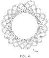
- FIGURE 4 is a frontal view of an actuated anastomotic ring.
- FIGURE 5 is a perspective view of the anastomotic ring applier device of FIGURE 1 with the distal portion of its ring deployment mechanism actuated.
- FIGURE 6 is a perspective of the device of FIGURE 1 with both the distal portion and the proximal portion of its ring deployment mechanism actuated.
- FIGURE 7 is a perspective exploded view of the anastomotic ring deployment mechanism of the device of FIGURE 1.
- FIGURE 8 is a perspective, cross-sectional exploded view of a proximal portion of the device of FIGURE 1 with a left housing half omitted.
- FIGURE 9 is a partial cross-sectional view of the distal portion of the device of FIGURE 1 inserted through an anastomotic opening.
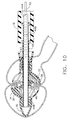
- FIGURE 10 is a partial cross-sectional view of the distal portion of the device of FIGURE 1 forming an anastomotic attachment between proximate gastrointestinal tissue walls.
- FIGURE 11 is a partial cross-sectional view of a proximal portion of the device of FIGURE 1.
- FIGURE 12 is a cross-sectional view taken along Plane 12 of FIG. 11.
- FIGURE 13 is a cross-sectional view taken along Plane 13 of FIG. 11.
- FIG. 1 depicts an applier 10 that is operable to deploy and actuate an anastomotic ring device (not pictured in FIG. 1) from a generally cylindrical shape to one having properties of a hollow rivet, or ring, capable of forming an anastomotic attachment at an anastomosis target site, such as in a bariatric gastric bypass of a morbidly obese patient.
- FIG. 2 depicts another applier 12. It will be appreciated that appliers 10, 12 may be used in a variety of ways, including but not limited to laparoscopically or endoscopically. Applier 12 is shown in FIG. 2 with an anastomotic ring 14 on a deployment mechanism 16.
- FIG. 2 anastomotic ring 14 is shown in the compressed, cylindrically-shaped position.
- deployment mechanism 16 of applier 12 has moved anastomotic ring 14 to the actuated, hollow rivet-shaped position.
- FIG. 4 is a close-up view of anastomotic ring 14 in the actuated position.
- Anastomotic ring 14 may comprise a shape memory effect (SME) material, such as nitinol by way of example only, that further assists in actuation to an engaging hollow rivet shape.
- SME shape memory effect
- Other suitable anastomotic ring 14 materials will be apparent to those of ordinary skill in the art.
- An exemplary anastomotic ring 14 is described in detail in U.S. Patent Application Publ. No. US 2003/0032967 to Park et al.
- proximal and distal are used herein with reference to a clinician gripping a handle of applier 10.
- spatial terms such as “right”, “left”, “vertical” and “horizontal” are used herein with respect to the drawings.
- surgical instruments are used in many orientations and positions, and these terms are not intended to be limiting and absolute.
- aspects of the invention have application to surgical procedures performed endoscopically and laparoscopically, as well as an open procedure or other procedures. Use herein of one of these or similar terms should not be construed to limit the present invention for use in only one category of surgical procedure.
- applier 10 of the present example comprises a handle 17 connected to an elongated shaft 18 having a proximal end 20 and a distal end 22.
- elongated shaft 18 is flexible, either along its entire length or at one or more joints.
- shaft 20 may alternatively be rigid, resilient, malleable, or have other properties.
- Distal end 22 of shaft 18 comprises a ring deployment mechanism 24.
- Deployment mechanism 24 may be actuated by a button or lever located on handle 17.
- handle 17 comprises a pair of actuator members 26, 28.
- actuator members 26, 28 comprise sliders. The functioning of exemplary actuator sliders 26, 28 will be described below. It will be appreciated, however, that actuator members 26, 28 may take a variety of other forms and have a variety of other functions.
- ring deployment mechanism 24 is located proximal to a tip 30.
- Applier 10 includes a feature to prevent tissue from becoming trapped in deployment mechanism 24 when applier 10 is inserted or extracted from the anastomosis site.
- a proximal sheath 32 and a distal sheath 34 are pictured.
- Ring deployment mechanism 24 of the present example is shown in an exploded perspective view, demonstrating how proximal sheath 32 fits over a plurality of proximal fingers 36, and distal sheath 34 fits over a plurality of distal fingers 38.
- Ring deployment mechanism 24 comprises a stationary molded actuation member 40.
- molded actuation member 40 may be formed using any suitable method other than molding.
- molded actuation member 40 comprises proximal fingers 36 and distal fingers 38. Molded actuation member 40 also has central portion 46, which is fixedly connected to middle tube 45. Middle tube 45 fixed in distal end 22 of shaft 18.
- Proximal fingers 36 are connected to first actuator slider 26 via push/pull cables 42 of shaft 18 (FIG. 12).
- Push/pull cables 42 are in communication with an outer tube 43, which is fixedly connected with proximal fingers 36.
- Distal fingers 38 are connected to second actuator slider 28 via an inner tubes 44A, 44B of shaft 18 (FIG. 13).
- Inner tube 44A is fixedly connected with inner tube 44B.
- Proximal fingers 36 and distal fingers 38 are each in a double-hinged relationship with a central portion 46 of molded actuation member 40.
- Other suitable configurations for ring deployment mechanism 24 will be apparent to those of ordinary skill in the art.
- FIGS. 8 and 11 show exemplary components of handle 17.
- distal movement of first actuator slider 26 communicates distal motion to proximal fingers 36 via push/pull cables 42, thereby causing proximal fingers 36 to actuate outwardly in the manner of an umbrella due to their hinged relationship with central portion 46.
- proximal movement of second actuator slider 28 communicates proximal motion to distal fingers 38 via inner tubes 44A, 44B, causing distal fingers 38 to actuate outwardly due to their hinged relationship with central portion 46.
- first actuator slider 26 actuates a proximal portion of anastomotic ring 14 from the compressed position to the actuated position
- proximal motion of second actuator slider 28 actuates a distal portion of anastomotic ring 14 from the compressed position to the actuated position
- handle 17 is configured such that first actuator slider 26 is in communication with distal fingers 38, while second actuator slider 28 is in communication with proximal fingers 36. Suitable configurations for accomplishing such relationships will be apparent to those of ordinary skill in the art. Alternatively, any other suitable means, method, or mechanism for actuating an anastomotic ring from a compressed position to an actuated position may be used.
- Fingers 36, 38 are configured to hold an anastomotic ring by engaging petals 51 prior to and during deployment of the anastomotic ring, and release petals 51 upon deployment of the anastomotic ring 51.
- Proximal fingers 36 and distal fingers 38 of the present example comprise gripping slots 48, each of which include an inwardly-directed retention tip 50. Gripping slots 48 may assist in retaining anastomotic ring 14 when it is in the compressed position, while retention tip 50 may allow anastomotic ring 14 to disengage from petals 51 of anastomotic ring 14 after it has been deployed in the actuated position.
- Other suitable configurations for fingers 36, 38 will be apparent to those of ordinary skill in the art.
- ring deployment mechanism 24 includes gaps 54 between proximal fingers 36 and between distal fingers 38.
- Proximal sheath 32 is adapted to cover proximal fingers 36
- distal sheath 34 is adapted to cover distal fingers 38 in order to prevent tissue from becoming lodged in gaps 54 during insertion and extraction of applier 10.
- distal sheath 34 is adapted to move to an actuated position along with distal fingers 38 in response to proximal movement by second actuator slider 28. This allows distal sheath 34 to prevent tissue from becoming trapped in gaps 54 during insertion or extraction of applier 10 without interfering with deployment of anastomotic ring 14 or requiring the surgeon to take the extra time and effort to retract the sheath.
- FIG. 6 shows both proximal fingers 36 and distal fingers 38 moved to the expanded position as a result of movement of actuator sliders 26, 28.
- Proximal and distal sheaths 32, 34 may be affixed to proximal and distal fingers 36, 38, respectively, by an adhesive, such as glue, by mechanical fasteners, or any other suitable means or method.
- proximal and distal sheaths 32, 34 comprise an elastomeric material that expands with proximal and distal fingers 36, 38, respectively.
- proximal and distal sheaths 32, 34 are made of braided thread. Even if the thread material has no elasticity, it may dilate readily, ensuring coverage of gaps 54 while allowing fingers 36, 38 to move to the expanded position.
- Other suitable materials and configurations for sheaths 32, 34 will be apparent to those of ordinary skill in the art.
- anastomotic ring 14 is held on ring deployment mechanism 24 by gripping slots 48 of proximal and distal fingers 36, 38.
- Applier 10 is inserted adjacent the anastomosis site, where an opening 56 is formed in two proximate gastrointestinal passages 58, 60, as shown in FIG. 9.
- proximal and distal sheaths 32, 34 act to prevent tissue from becoming trapped in gaps 54.
- sheaths 32, 34 may serve a variety of other purposes.
- first and second actuator sliders 26, 28 may be moved to their respective activated positions, causing fingers 36, 38 to actuate outwardly. This may expand anastomotic ring 14 from its compressed, cylindrical-shaped position to its actuated, hollow rivet-shaped position, forming an anastomotic attachment between the gastrointestinal tissue walls.
- Other applications and methods of operating applier 10 will be apparent to those of ordinary skill in the art.
Priority Applications (1)
| Application Number | Priority Date | Filing Date | Title |
|---|---|---|---|
| HK07104183A HK1097171A1 (en) | 2005-05-03 | 2007-04-20 | Sheath for enabling insertion and extraction of anastomotic ring applier |
Applications Claiming Priority (1)
| Application Number | Priority Date | Filing Date | Title |
|---|---|---|---|
| US11/120,824 US7632285B2 (en) | 2005-05-03 | 2005-05-03 | Sheath for enabling insertion and extraction of anastomotic ring applier |
Publications (2)
| Publication Number | Publication Date |
|---|---|
| EP1719456A1 true EP1719456A1 (fr) | 2006-11-08 |
| EP1719456B1 EP1719456B1 (fr) | 2008-03-26 |
Family
ID=36888587
Family Applications (1)
| Application Number | Title | Priority Date | Filing Date |
|---|---|---|---|
| EP06252335A Active EP1719456B1 (fr) | 2005-05-03 | 2006-05-02 | Gaine permettant l'insertion et l'extraction d'un applicateur de bague anastomotique |
Country Status (15)
| Country | Link |
|---|---|
| US (1) | US7632285B2 (fr) |
| EP (1) | EP1719456B1 (fr) |
| JP (1) | JP2006312052A (fr) |
| KR (1) | KR20060115600A (fr) |
| CN (1) | CN100579472C (fr) |
| AT (1) | ATE390085T1 (fr) |
| AU (1) | AU2006201715B2 (fr) |
| BR (1) | BRPI0601511B8 (fr) |
| CA (1) | CA2545795C (fr) |
| DE (1) | DE602006000782T2 (fr) |
| HK (1) | HK1097171A1 (fr) |
| IL (1) | IL175289A0 (fr) |
| RU (1) | RU2428131C2 (fr) |
| SG (1) | SG126912A1 (fr) |
| TW (1) | TWI400058B (fr) |
Cited By (1)
| Publication number | Priority date | Publication date | Assignee | Title |
|---|---|---|---|---|
| EP3939526A4 (fr) * | 2019-03-12 | 2022-12-07 | Nikkotech,Co,Ltd. | Équipement chirurgical minimalement invasif |
Families Citing this family (4)
| Publication number | Priority date | Publication date | Assignee | Title |
|---|---|---|---|---|
| US20070021759A1 (en) * | 2005-07-22 | 2007-01-25 | Ethicon Endo-Surgery, Inc. | Flexible endoscopic anastomotic ring applier device |
| US20110087252A1 (en) * | 2009-10-08 | 2011-04-14 | Wilson-Cook Medical Inc. | Biliary decompression and anastomosis stent |
| CN110868965B (zh) * | 2017-05-03 | 2021-12-28 | 波士顿科学国际有限公司 | 具有密封组件的医疗装置 |
| CN109009290B (zh) * | 2018-09-13 | 2024-04-23 | 西安交通大学医学院第一附属医院 | 一种磁吻合胆道再通装置 |
Citations (4)
| Publication number | Priority date | Publication date | Assignee | Title |
|---|---|---|---|---|
| US6428550B1 (en) * | 1999-05-18 | 2002-08-06 | Cardica, Inc. | Sutureless closure and deployment system for connecting blood vessels |
| US20030191482A1 (en) * | 1998-10-22 | 2003-10-09 | Suyker Wilhelmus Joseph Leonardus | Mechanical anastomosis system for hollow structures |
| WO2004098417A1 (fr) * | 2003-04-16 | 2004-11-18 | Tyco Healthcare Group Lp | Methode et appareil pour anastomose apres prostatectomie radicale faisant appel a un element d'ancrage destine a entrer en prise avec un vaisseau du corps et a des fils de suture deployables |
| EP1520531A1 (fr) * | 2003-09-30 | 2005-04-06 | Ethicon Endo-Surgery | Applicateur pour anastomose |
Family Cites Families (13)
| Publication number | Priority date | Publication date | Assignee | Title |
|---|---|---|---|---|
| JPH06327683A (ja) * | 1993-05-19 | 1994-11-29 | Olympus Optical Co Ltd | 外科用縫合具 |
| US5443477A (en) * | 1994-02-10 | 1995-08-22 | Stentco, Inc. | Apparatus and method for deployment of radially expandable stents by a mechanical linkage |
| US5904697A (en) | 1995-02-24 | 1999-05-18 | Heartport, Inc. | Devices and methods for performing a vascular anastomosis |
| US5855312A (en) | 1996-07-25 | 1999-01-05 | Toledano; Haviv | Flexible annular stapler for closed surgery of hollow organs |
| NL1007349C2 (nl) * | 1997-10-24 | 1999-04-27 | Suyker Wilhelmus Joseph Leonardus | Systeem voor het mechanisch vervaardigen van anastomoses tussen holle structuren; alsmede inrichting en applicator voor gebruik daarbij. |
| US6451029B1 (en) | 1999-08-23 | 2002-09-17 | University Of South Florida | Intestinal stapling device and method |
| JP2002272748A (ja) * | 2001-03-14 | 2002-09-24 | Terumo Corp | 血管外翻器具 |
| EP1401337B1 (fr) * | 2001-06-20 | 2011-06-15 | Park Medical, LLC | Dispositif anastomotique |
| JP4504599B2 (ja) * | 2001-07-27 | 2010-07-14 | 治文 加藤 | 吻合用補助具 |
| US6726714B2 (en) * | 2001-08-09 | 2004-04-27 | Scimed Life Systems, Inc. | Stent delivery system |
| EP1448262A4 (fr) * | 2001-10-30 | 2008-08-06 | Applied Med Resources | Catheter d'exclusion vasculaire |
| US7608086B2 (en) * | 2003-09-30 | 2009-10-27 | Ethicon Endo-Surgery, Inc. | Anastomosis wire ring device |
| US20050070939A1 (en) * | 2003-09-30 | 2005-03-31 | Jean Beaupre | Unfolding anastomosis ring device |
-
2005
- 2005-05-03 US US11/120,824 patent/US7632285B2/en active Active
-
2006
- 2006-04-26 AU AU2006201715A patent/AU2006201715B2/en not_active Ceased
- 2006-04-27 IL IL175289A patent/IL175289A0/en unknown
- 2006-04-27 SG SG200602861A patent/SG126912A1/en unknown
- 2006-05-02 AT AT06252335T patent/ATE390085T1/de not_active IP Right Cessation
- 2006-05-02 TW TW095115635A patent/TWI400058B/zh not_active IP Right Cessation
- 2006-05-02 EP EP06252335A patent/EP1719456B1/fr active Active
- 2006-05-02 DE DE602006000782T patent/DE602006000782T2/de active Active
- 2006-05-02 CA CA2545795A patent/CA2545795C/fr not_active Expired - Fee Related
- 2006-05-02 JP JP2006128518A patent/JP2006312052A/ja active Pending
- 2006-05-02 RU RU2006114818/14A patent/RU2428131C2/ru not_active IP Right Cessation
- 2006-05-03 BR BRPI0601511A patent/BRPI0601511B8/pt active IP Right Grant
- 2006-05-03 KR KR1020060039930A patent/KR20060115600A/ko not_active Application Discontinuation
- 2006-05-08 CN CN200610077480A patent/CN100579472C/zh active Active
-
2007
- 2007-04-20 HK HK07104183A patent/HK1097171A1/xx not_active IP Right Cessation
Patent Citations (4)
| Publication number | Priority date | Publication date | Assignee | Title |
|---|---|---|---|---|
| US20030191482A1 (en) * | 1998-10-22 | 2003-10-09 | Suyker Wilhelmus Joseph Leonardus | Mechanical anastomosis system for hollow structures |
| US6428550B1 (en) * | 1999-05-18 | 2002-08-06 | Cardica, Inc. | Sutureless closure and deployment system for connecting blood vessels |
| WO2004098417A1 (fr) * | 2003-04-16 | 2004-11-18 | Tyco Healthcare Group Lp | Methode et appareil pour anastomose apres prostatectomie radicale faisant appel a un element d'ancrage destine a entrer en prise avec un vaisseau du corps et a des fils de suture deployables |
| EP1520531A1 (fr) * | 2003-09-30 | 2005-04-06 | Ethicon Endo-Surgery | Applicateur pour anastomose |
Cited By (1)
| Publication number | Priority date | Publication date | Assignee | Title |
|---|---|---|---|---|
| EP3939526A4 (fr) * | 2019-03-12 | 2022-12-07 | Nikkotech,Co,Ltd. | Équipement chirurgical minimalement invasif |
Also Published As
| Publication number | Publication date |
|---|---|
| CN1857176A (zh) | 2006-11-08 |
| HK1097171A1 (en) | 2007-06-22 |
| DE602006000782T2 (de) | 2009-04-30 |
| JP2006312052A (ja) | 2006-11-16 |
| RU2006114818A (ru) | 2007-11-27 |
| IL175289A0 (en) | 2006-09-05 |
| US7632285B2 (en) | 2009-12-15 |
| AU2006201715B2 (en) | 2012-03-22 |
| AU2006201715A1 (en) | 2006-11-23 |
| CA2545795C (fr) | 2014-02-11 |
| CA2545795A1 (fr) | 2006-11-03 |
| US20060253133A1 (en) | 2006-11-09 |
| RU2428131C2 (ru) | 2011-09-10 |
| SG126912A1 (en) | 2006-11-29 |
| TWI400058B (zh) | 2013-07-01 |
| EP1719456B1 (fr) | 2008-03-26 |
| BRPI0601511B1 (pt) | 2018-03-13 |
| KR20060115600A (ko) | 2006-11-09 |
| CN100579472C (zh) | 2010-01-13 |
| ATE390085T1 (de) | 2008-04-15 |
| BRPI0601511B8 (pt) | 2021-06-22 |
| DE602006000782D1 (de) | 2008-05-08 |
| BRPI0601511A (pt) | 2006-12-26 |
| TW200701932A (en) | 2007-01-16 |
Similar Documents
| Publication | Publication Date | Title |
|---|---|---|
| US7534247B2 (en) | Sheathless anastomotic ring applier device | |
| AU2006203054B2 (en) | Anastomotic ring applier for use in colorectal applications | |
| EP1719458B1 (fr) | Applicateur de bague anastomotique à actionnement par double mouvement | |
| EP1719456B1 (fr) | Gaine permettant l'insertion et l'extraction d'un applicateur de bague anastomotique | |
| EP1745751A1 (fr) | Dispositif pour le placement endoscopique des anneaux d'anastomose | |
| EP1719457B1 (fr) | Applicateur de bague anastomotique avec visualisation frontale et rétrograde | |
| EP1719453A1 (fr) | Applicateur pour anastomose | |
| MXPA06004947A (en) | Sheath for enabling insertion and extraction of anastomotic ring applier | |
| MXPA06005163A (en) | Anastomotic ring applier with double motion actuation | |
| MXPA06008305A (en) | Anastomotic ring applier for use in colorectal applications |
Legal Events
| Date | Code | Title | Description |
|---|---|---|---|
| PUAI | Public reference made under article 153(3) epc to a published international application that has entered the european phase |
Free format text: ORIGINAL CODE: 0009012 |
|
| AK | Designated contracting states |
Kind code of ref document: A1 Designated state(s): AT BE BG CH CY CZ DE DK EE ES FI FR GB GR HU IE IS IT LI LT LU LV MC NL PL PT RO SE SI SK TR |
|
| AX | Request for extension of the european patent |
Extension state: AL BA HR MK YU |
|
| 17P | Request for examination filed |
Effective date: 20070416 |
|
| REG | Reference to a national code |
Ref country code: HK Ref legal event code: DE Ref document number: 1097171 Country of ref document: HK |
|
| 17Q | First examination report despatched |
Effective date: 20070524 |
|
| AKX | Designation fees paid |
Designated state(s): AT BE BG CH CY CZ DE DK EE ES FI FR GB GR HU IE IS IT LI LT LU LV MC NL PL PT RO SE SI SK TR |
|
| GRAP | Despatch of communication of intention to grant a patent |
Free format text: ORIGINAL CODE: EPIDOSNIGR1 |
|
| GRAS | Grant fee paid |
Free format text: ORIGINAL CODE: EPIDOSNIGR3 |
|
| GRAA | (expected) grant |
Free format text: ORIGINAL CODE: 0009210 |
|
| AK | Designated contracting states |
Kind code of ref document: B1 Designated state(s): AT BE BG CH CY CZ DE DK EE ES FI FR GB GR HU IE IS IT LI LT LU LV MC NL PL PT RO SE SI SK TR |
|
| REG | Reference to a national code |
Ref country code: GB Ref legal event code: FG4D |
|
| REG | Reference to a national code |
Ref country code: CH Ref legal event code: EP Ref country code: IE Ref legal event code: FG4D |
|
| REF | Corresponds to: |
Ref document number: 602006000782 Country of ref document: DE Date of ref document: 20080508 Kind code of ref document: P |
|
| REG | Reference to a national code |
Ref country code: HK Ref legal event code: GR Ref document number: 1097171 Country of ref document: HK |
|
| PG25 | Lapsed in a contracting state [announced via postgrant information from national office to epo] |
Ref country code: FI Free format text: LAPSE BECAUSE OF FAILURE TO SUBMIT A TRANSLATION OF THE DESCRIPTION OR TO PAY THE FEE WITHIN THE PRESCRIBED TIME-LIMIT Effective date: 20080326 |
|
| PG25 | Lapsed in a contracting state [announced via postgrant information from national office to epo] |
Ref country code: AT Free format text: LAPSE BECAUSE OF FAILURE TO SUBMIT A TRANSLATION OF THE DESCRIPTION OR TO PAY THE FEE WITHIN THE PRESCRIBED TIME-LIMIT Effective date: 20080326 |
|
| PG25 | Lapsed in a contracting state [announced via postgrant information from national office to epo] |
Ref country code: LV Free format text: LAPSE BECAUSE OF FAILURE TO SUBMIT A TRANSLATION OF THE DESCRIPTION OR TO PAY THE FEE WITHIN THE PRESCRIBED TIME-LIMIT Effective date: 20080326 Ref country code: BE Free format text: LAPSE BECAUSE OF FAILURE TO SUBMIT A TRANSLATION OF THE DESCRIPTION OR TO PAY THE FEE WITHIN THE PRESCRIBED TIME-LIMIT Effective date: 20080326 Ref country code: SI Free format text: LAPSE BECAUSE OF FAILURE TO SUBMIT A TRANSLATION OF THE DESCRIPTION OR TO PAY THE FEE WITHIN THE PRESCRIBED TIME-LIMIT Effective date: 20080326 Ref country code: PL Free format text: LAPSE BECAUSE OF FAILURE TO SUBMIT A TRANSLATION OF THE DESCRIPTION OR TO PAY THE FEE WITHIN THE PRESCRIBED TIME-LIMIT Effective date: 20080326 |
|
| PG25 | Lapsed in a contracting state [announced via postgrant information from national office to epo] |
Ref country code: SK Free format text: LAPSE BECAUSE OF FAILURE TO SUBMIT A TRANSLATION OF THE DESCRIPTION OR TO PAY THE FEE WITHIN THE PRESCRIBED TIME-LIMIT Effective date: 20080326 Ref country code: CZ Free format text: LAPSE BECAUSE OF FAILURE TO SUBMIT A TRANSLATION OF THE DESCRIPTION OR TO PAY THE FEE WITHIN THE PRESCRIBED TIME-LIMIT Effective date: 20080326 Ref country code: ES Free format text: LAPSE BECAUSE OF FAILURE TO SUBMIT A TRANSLATION OF THE DESCRIPTION OR TO PAY THE FEE WITHIN THE PRESCRIBED TIME-LIMIT Effective date: 20080707 Ref country code: SE Free format text: LAPSE BECAUSE OF FAILURE TO SUBMIT A TRANSLATION OF THE DESCRIPTION OR TO PAY THE FEE WITHIN THE PRESCRIBED TIME-LIMIT Effective date: 20080626 Ref country code: PT Free format text: LAPSE BECAUSE OF FAILURE TO SUBMIT A TRANSLATION OF THE DESCRIPTION OR TO PAY THE FEE WITHIN THE PRESCRIBED TIME-LIMIT Effective date: 20080901 |
|
| ET | Fr: translation filed | ||
| PG25 | Lapsed in a contracting state [announced via postgrant information from national office to epo] |
Ref country code: RO Free format text: LAPSE BECAUSE OF FAILURE TO SUBMIT A TRANSLATION OF THE DESCRIPTION OR TO PAY THE FEE WITHIN THE PRESCRIBED TIME-LIMIT Effective date: 20080326 |
|
| PG25 | Lapsed in a contracting state [announced via postgrant information from national office to epo] |
Ref country code: MC Free format text: LAPSE BECAUSE OF NON-PAYMENT OF DUE FEES Effective date: 20080531 Ref country code: IS Free format text: LAPSE BECAUSE OF FAILURE TO SUBMIT A TRANSLATION OF THE DESCRIPTION OR TO PAY THE FEE WITHIN THE PRESCRIBED TIME-LIMIT Effective date: 20080726 |
|
| PG25 | Lapsed in a contracting state [announced via postgrant information from national office to epo] |
Ref country code: LT Free format text: LAPSE BECAUSE OF FAILURE TO SUBMIT A TRANSLATION OF THE DESCRIPTION OR TO PAY THE FEE WITHIN THE PRESCRIBED TIME-LIMIT Effective date: 20080326 Ref country code: EE Free format text: LAPSE BECAUSE OF FAILURE TO SUBMIT A TRANSLATION OF THE DESCRIPTION OR TO PAY THE FEE WITHIN THE PRESCRIBED TIME-LIMIT Effective date: 20080326 Ref country code: DK Free format text: LAPSE BECAUSE OF FAILURE TO SUBMIT A TRANSLATION OF THE DESCRIPTION OR TO PAY THE FEE WITHIN THE PRESCRIBED TIME-LIMIT Effective date: 20080326 |
|
| PLBE | No opposition filed within time limit |
Free format text: ORIGINAL CODE: 0009261 |
|
| STAA | Information on the status of an ep patent application or granted ep patent |
Free format text: STATUS: NO OPPOSITION FILED WITHIN TIME LIMIT |
|
| 26N | No opposition filed |
Effective date: 20081230 |
|
| PG25 | Lapsed in a contracting state [announced via postgrant information from national office to epo] |
Ref country code: BG Free format text: LAPSE BECAUSE OF FAILURE TO SUBMIT A TRANSLATION OF THE DESCRIPTION OR TO PAY THE FEE WITHIN THE PRESCRIBED TIME-LIMIT Effective date: 20080626 Ref country code: IE Free format text: LAPSE BECAUSE OF NON-PAYMENT OF DUE FEES Effective date: 20080502 |
|
| PG25 | Lapsed in a contracting state [announced via postgrant information from national office to epo] |
Ref country code: CY Free format text: LAPSE BECAUSE OF FAILURE TO SUBMIT A TRANSLATION OF THE DESCRIPTION OR TO PAY THE FEE WITHIN THE PRESCRIBED TIME-LIMIT Effective date: 20080326 |
|
| PG25 | Lapsed in a contracting state [announced via postgrant information from national office to epo] |
Ref country code: HU Free format text: LAPSE BECAUSE OF FAILURE TO SUBMIT A TRANSLATION OF THE DESCRIPTION OR TO PAY THE FEE WITHIN THE PRESCRIBED TIME-LIMIT Effective date: 20080927 Ref country code: LU Free format text: LAPSE BECAUSE OF NON-PAYMENT OF DUE FEES Effective date: 20080502 |
|
| PG25 | Lapsed in a contracting state [announced via postgrant information from national office to epo] |
Ref country code: TR Free format text: LAPSE BECAUSE OF FAILURE TO SUBMIT A TRANSLATION OF THE DESCRIPTION OR TO PAY THE FEE WITHIN THE PRESCRIBED TIME-LIMIT Effective date: 20080326 |
|
| PG25 | Lapsed in a contracting state [announced via postgrant information from national office to epo] |
Ref country code: GR Free format text: LAPSE BECAUSE OF FAILURE TO SUBMIT A TRANSLATION OF THE DESCRIPTION OR TO PAY THE FEE WITHIN THE PRESCRIBED TIME-LIMIT Effective date: 20080627 |
|
| REG | Reference to a national code |
Ref country code: CH Ref legal event code: PL |
|
| PG25 | Lapsed in a contracting state [announced via postgrant information from national office to epo] |
Ref country code: LI Free format text: LAPSE BECAUSE OF NON-PAYMENT OF DUE FEES Effective date: 20100531 Ref country code: CH Free format text: LAPSE BECAUSE OF NON-PAYMENT OF DUE FEES Effective date: 20100531 |
|
| REG | Reference to a national code |
Ref country code: NL Ref legal event code: T3 |
|
| REG | Reference to a national code |
Ref country code: FR Ref legal event code: PLFP Year of fee payment: 11 |
|
| REG | Reference to a national code |
Ref country code: FR Ref legal event code: PLFP Year of fee payment: 12 |
|
| REG | Reference to a national code |
Ref country code: FR Ref legal event code: PLFP Year of fee payment: 13 |
|
| PGFP | Annual fee paid to national office [announced via postgrant information from national office to epo] |
Ref country code: SE Payment date: 20190503 Year of fee payment: 5 |
|
| REG | Reference to a national code |
Ref country code: DE Ref legal event code: R119 Ref document number: 602006000782 Country of ref document: DE |
|
| PG25 | Lapsed in a contracting state [announced via postgrant information from national office to epo] |
Ref country code: DE Free format text: LAPSE BECAUSE OF NON-PAYMENT OF DUE FEES Effective date: 20201201 |
|
| PGFP | Annual fee paid to national office [announced via postgrant information from national office to epo] |
Ref country code: NL Payment date: 20220420 Year of fee payment: 17 |
|
| REG | Reference to a national code |
Ref country code: FR Ref legal event code: PLFP Year of fee payment: 18 |
|
| PGFP | Annual fee paid to national office [announced via postgrant information from national office to epo] |
Ref country code: GB Payment date: 20230330 Year of fee payment: 18 |
|
| PGFP | Annual fee paid to national office [announced via postgrant information from national office to epo] |
Ref country code: IT Payment date: 20230412 Year of fee payment: 18 Ref country code: FR Payment date: 20230411 Year of fee payment: 18 |
|
| REG | Reference to a national code |
Ref country code: NL Ref legal event code: MM Effective date: 20230601 |
|
| PG25 | Lapsed in a contracting state [announced via postgrant information from national office to epo] |
Ref country code: NL Free format text: LAPSE BECAUSE OF NON-PAYMENT OF DUE FEES Effective date: 20230601 |