EP1718878B1 - Lagervorrichtung zur lagerung eines hochtourig laufenden rotors - Google Patents
Lagervorrichtung zur lagerung eines hochtourig laufenden rotors Download PDFInfo
- Publication number
- EP1718878B1 EP1718878B1 EP04821735A EP04821735A EP1718878B1 EP 1718878 B1 EP1718878 B1 EP 1718878B1 EP 04821735 A EP04821735 A EP 04821735A EP 04821735 A EP04821735 A EP 04821735A EP 1718878 B1 EP1718878 B1 EP 1718878B1
- Authority
- EP
- European Patent Office
- Prior art keywords
- screw
- bearing
- pressure distribution
- inner sleeve
- distribution element
- Prior art date
- Legal status (The legal status is an assumption and is not a legal conclusion. Google has not performed a legal analysis and makes no representation as to the accuracy of the status listed.)
- Expired - Lifetime
Links
- 238000009826 distribution Methods 0.000 claims abstract description 38
- 238000013016 damping Methods 0.000 claims description 54
- 239000004033 plastic Substances 0.000 claims description 16
- 239000013013 elastic material Substances 0.000 claims description 2
- 238000002347 injection Methods 0.000 claims description 2
- 239000007924 injection Substances 0.000 claims description 2
- 238000007383 open-end spinning Methods 0.000 abstract description 4
- 230000000717 retained effect Effects 0.000 abstract 1
- 238000009987 spinning Methods 0.000 description 9
- 238000003860 storage Methods 0.000 description 6
- 238000003466 welding Methods 0.000 description 4
- 238000012423 maintenance Methods 0.000 description 3
- 230000007423 decrease Effects 0.000 description 2
- 238000006073 displacement reaction Methods 0.000 description 2
- 238000004519 manufacturing process Methods 0.000 description 2
- 230000003014 reinforcing effect Effects 0.000 description 2
- 229910000831 Steel Inorganic materials 0.000 description 1
- 230000005540 biological transmission Effects 0.000 description 1
- 230000007797 corrosion Effects 0.000 description 1
- 238000005260 corrosion Methods 0.000 description 1
- 230000001419 dependent effect Effects 0.000 description 1
- 239000000428 dust Substances 0.000 description 1
- 239000000835 fiber Substances 0.000 description 1
- 238000010438 heat treatment Methods 0.000 description 1
- 238000009434 installation Methods 0.000 description 1
- 239000000463 material Substances 0.000 description 1
- 230000000149 penetrating effect Effects 0.000 description 1
- 230000002093 peripheral effect Effects 0.000 description 1
- 238000003825 pressing Methods 0.000 description 1
- 230000002035 prolonged effect Effects 0.000 description 1
- 239000010959 steel Substances 0.000 description 1
- 239000004636 vulcanized rubber Substances 0.000 description 1
Images

Classifications
-
- F—MECHANICAL ENGINEERING; LIGHTING; HEATING; WEAPONS; BLASTING
- F16—ENGINEERING ELEMENTS AND UNITS; GENERAL MEASURES FOR PRODUCING AND MAINTAINING EFFECTIVE FUNCTIONING OF MACHINES OR INSTALLATIONS; THERMAL INSULATION IN GENERAL
- F16C—SHAFTS; FLEXIBLE SHAFTS; ELEMENTS OR CRANKSHAFT MECHANISMS; ROTARY BODIES OTHER THAN GEARING ELEMENTS; BEARINGS
- F16C27/00—Elastic or yielding bearings or bearing supports, for exclusively rotary movement
- F16C27/06—Elastic or yielding bearings or bearing supports, for exclusively rotary movement by means of parts of rubber or like materials
-
- D—TEXTILES; PAPER
- D01—NATURAL OR MAN-MADE THREADS OR FIBRES; SPINNING
- D01H—SPINNING OR TWISTING
- D01H4/00—Open-end spinning machines or arrangements for imparting twist to independently moving fibres separated from slivers; Piecing arrangements therefor; Covering endless core threads with fibres by open-end spinning techniques
- D01H4/04—Open-end spinning machines or arrangements for imparting twist to independently moving fibres separated from slivers; Piecing arrangements therefor; Covering endless core threads with fibres by open-end spinning techniques imparting twist by contact of fibres with a running surface
- D01H4/08—Rotor spinning, i.e. the running surface being provided by a rotor
- D01H4/12—Rotor bearings; Arrangements for driving or stopping
Definitions
- the invention relates to a bearing device for supporting a high-speed rotor according to the preamble of claim 1.
- Such high-speed rotor bearings are used on open-end spinning machines and are mounted in the inner sleeve of a damping device in order to reduce the occurring high dynamic forces can.
- the inner sleeve is held by rubber-elastic elements in the rotor housing.
- Between rotor bearing and inner sleeve of the damping device as rigid as possible connection is made to prevent caused by inherent elasticity additional natural resonances arise.
- the rotor bearing must be axially adjustable with the rotor in the rotor housing in order to adjust the rotor in the correct position to the elements of the fiber feed and the thread take-off can. This axial positioning can be done by moving the rotor bearing together with the annular damping elements of the damping device in the rotor housing or by moving the rotor bearing alone in already prefixed damping elements.
- the ring-shaped damping elements settle after prolonged spinning operation by dirt, dust and vibration corrosion in the rotor housing. They can then no longer be moved sensitively to adjust the rotor bearing axially. Moving the rotor bearing together with the Damping elements in the rotor housing is therefore avoided if possible. If damping elements and rotor bearings are installed and maintained as independent components, the adjustment of the rotor bearing therefore preferably takes place by displacement of the rotor bearing in the damping elements.
- a bearing assembly for spinning rotors on open-end spinning machines wherein the inner sleeve of the damping elements comprises a centrally disposed circumferential rim with a continuous threaded bore.
- a cylinder head screw with slotted head and opposite tip is screwed into the threaded hole up to the stop of the screw head.
- To the bearing outer ring runs a groove with an inserted ring.
- the ring is usually made of plastic or a similar deformable material. The tip of the cylinder screw penetrates into the plastic ring and thus clamps the rotor bearing firmly.
- the DE 199 01 565 A1 shows a storage of a spinning rotor of an open-end spinning machine with a relubrication system.
- the relubrication system is expensive in terms of the required components and assembly.
- the mounting of the bearing outer ring on the inner sleeve of the damping device by means of a cylinder screw with slotted head.
- the screw is not held by a thread introduced into the inner sleeve, but rather by an internally threaded set piece connected fixedly to the inner sleeve.
- the attachment consists of a welded nut. When tightening the screw, the force acts in the direction of detachment of the nut.
- the nut must be attached as well as it can be achieved by welding or the internal thread must be part of the damping inner sleeve.
- the screw has no tip which penetrates into the running around the inner sleeve plastic ring. The screw only presses flat on the existing plastic ring here.
- the fixation of the bearing outer ring is done only by clamping. A support of the clamping by plastic deformation by means of a penetrating tip does not occur in this embodiment.
- the bearing device ensures a secure and durable attachment between the damping inner sleeve and bearing ring.
- a plastic clamping ring and the introduction of circumferential grooves in the bearing ring is no longer required. Deformations caused by welding on a nut can no longer occur.
- the inventive arrangement of the screw, the connection between the bearing ring and damping inner sleeve is made by train.
- the connection between the pressure distribution element and the damping inner sleeve is reinforced and not claimed as in the prior art. This results in the possibility of releasable attachment, resulting in a reduction of the convincedsaufwnades over the prior art.
- the screw If the screw is held in position released from the internal thread of the bearing ring by the pressure distribution element, the screw becomes a captive part of the damping inner sleeve.
- the bearing device is thus easier to assemble.
- the pressure distribution element has ring-segment-shaped retaining arms, with which it can be latched onto the damping inner sleeve, a simple and rapid application of the pressure distribution element to the damping inner sleeve is possible.
- the pressure distribution element remains axially limited as described for a simple adjustment.
- An embodiment of the pressure distribution element according to claim 6 and a design of the screw according to claim 7 ensure a good support of the screw head and a good distribution of the contact pressure on the inner damping sleeve. Due to the molded disc secure mounting of the screw in notches of the locking hooks is possible.
- a complex relubrication device as for example from the DE 199 01 565 A1 is known, omitted. Relubrication is easy.
- Pressure distribution elements according to claim 10 and according to claim 11 allow a cost-effective production.
- connection of bearing ring and damping inner sleeve by means of clamping by friction and plastic deformation is advantageously replaced by a positive and wear-free connection.
- the storage device according to the invention advantageously allows a secure bearing mounting and a simple relubrication by means of the two components pressure distribution element and screw. All parts are inexpensive to produce.
- the bearing device is easy to assemble and facilitates maintenance and adjustment.
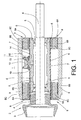
- Fig. 1 shows a storage device 1 for supporting a spinning rotor 2.
- the spinning rotor 2 consists of a Rotorseller 3 and a rotor shaft 4.
- the rotor shaft 4 is rotatably supported by a ball bearing device 5 in a bearing ring 6.
- the bearing ring 6 is enclosed by a damping inner sleeve 7, which in turn is secured in rubber-elastic annular damping elements 8.
- the damping elements 8 each comprise an inner reinforcing ring 8A and a steel outer reinforcing ring 8B and a vulcanized rubber ring 8C and are held in a housing 9.
- the bearing ring 6 has a continuous internal thread 10 into which a screw 11 engages.
- the screw 11 is designed as a cylinder head screw with hexagon socket 12.
- a relubrication bore 13 leads.
- the ball bearing device 5 can be relubricated in a simple manner and without great structural complexity.
- the screw 11 engages through an opening 14 of the damping inner sleeve 7 and applied in the attracted state, a pressure distribution element 15 with a force in the direction of bearing ring 6 and presses the damping inner sleeve 7 against the bearing ring 6.
- a rigid connection between the bearing ring 6 and the damping inner sleeve 7 is made and the bearing ring 6 fixed in position.
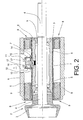
- Fig. 2 engages the screw 11 no longer in the internal thread 10 and is located in a detached and spaced from the bearing ring 6 position.
- the screw 11 has an integrally formed on the cylinder head disc 16.
- the disc 16 engages in the position spaced from the bearing ring 6 position in notches 17 of two opposing elastic latching hooks 18 of the pressure distribution element 15 a. The distance between the latching hooks 18 decreases towards their free ends.
- the disc 16 presses the latching hooks 18 apart in the course of unscrewing and finally snaps into the notches 17 of the latching hooks 18.
- the screw 11 is held securely and easily by the pressure distribution element 15, can not be lost and is already suitably positioned for later screwing into the internal thread 10 of the bearing ring 6.
- the bearing ring 6 of the rotor bearing can be axially displaced and expanded in this position of the screw 11.
- a limited axial displacement of the bearing ring 6 is already possible when the screw 11 is turned out only a few turns and thus the pressing of the damping inner sleeve is lifted to the bearing ring 6.
- the screw 11 can thereby move in the opening 14, which is designed as a slot in the axial direction, and takes the pressure distribution element 15 with.
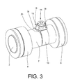
- the pressure distribution element 15 of Fig. 2 with the screw 11 in the detached from the internal thread 10 of the bearing ring 6 position, wherein the bearing ring 6 is expanded together with the spinning rotor 2 is in the Fig. 3 shown in perspective.
- the damping device comprises the annular damping elements 8 and the damping inner sleeve 7, wherein the damping elements 8 are applied to the ends of the damping inner sleeve 7.
- the pressure distribution element 15 is arranged so that the screw 11 by the in the Fig. 3 invisible opening 14 can pass through.
- the screw 11 is held by two latching hooks 18.
- the holding arms 19 have sufficient elasticity to so far open when applying the pressure distribution element 15 on the inner damping sleeve 7, that the pressure distribution element 15 can be snapped, and then to put on the damping inner sleeve 7.
- the pressure distribution element 15 is adapted to the damping inner sleeve 7 facing side of the cylindrical shape of the damping inner sleeve 7.
- the latching hooks 18 are arranged on the edge of a flat support 20, on which the underside of the cylinder head of the screw 11 rests. This allows a good distribution of the contact pressure when the screw 11 is tightened.
- FIG. 4 shows one opposite the FIGS. 1 to 3 enlarged view of the pressure distribution element 15.
- the curvature on the inside of the support arms 19 can be clearly seen in this illustration.
- the latching hooks 18 with the notches 17 can by the arrangement opposite each other, the well formed on the cylinder head of the screw 11 disc 16 well and hold when the screw 11 has been unscrewed from the internal thread 10.
- the pressure distribution element 15 is designed as a plastic injection molded part.
Landscapes
- Engineering & Computer Science (AREA)
- Mechanical Engineering (AREA)
- Textile Engineering (AREA)
- General Engineering & Computer Science (AREA)
- Spinning Or Twisting Of Yarns (AREA)
- Processing And Handling Of Plastics And Other Materials For Molding In General (AREA)
- Rotary Pumps (AREA)
- Rolling Contact Bearings (AREA)
- Support Of The Bearing (AREA)
- Vibration Prevention Devices (AREA)
Description
- Die Erfindung betrifft eine Lagervorrichtung zur Lagerung eines hochtourig laufenden Rotors gemäß dem Oberbegriff des Anspruchs 1.
- Derartige hochtourige Rotorlagerungen werden an Open-End-Spinnmaschinen eingesetzt und sind in der Innenhülse einer Dämpfungseinrichtung befestigt, um die auftretenden hohen dynamischen Kräfte abbauen zu können. Die Innenhülse ist von gummielastischen Elementen im Rotorgehäuse gehaltert. Zwischen Rotorlagerung und Innenhülse der Dämpfungseinrichtung wird eine möglichst starre Verbindung hergestellt, um zu verhindern, daß durch Eigenelastizität bedingte zusätzliche Eigenresonanzen entstehen. Die Rotorlagerung muß mit dem Rotor axial im Rotorgehäuse justierbar sein, um den Rotor in die richtige Position zu den Elementen der Fasereinspeisung und des Fadenabzugs einstellen zu können. Diese axiale Positionierung kann durch Verschieben der Rotorlagerung zusammen mit den ringförmigen Dämpfungselementen der Dämpfungseinrichtung im Rotorgehäuse vorgenommen werden oder durch Verschieben der Rotorlagerung allein in bereits vorfixierten Dämpfungselementen.
- Die ringförmigen Dämpfungselemente setzen sich nach längerem Spinnbetrieb durch Schmutz, Staub und Schwingungskorrosion im Rotorgehäuse fest. Sie lassen sich dann nicht mehr feinfühlig zum Justieren der Rotorlagerung axial verschieben. Das Verschieben der Rotorlagerung zusammen mit den Dämpfungselementen im Rotorgehäuse wird daher nach Möglichkeit vermieden. Werden Dämpfungselemente und Rotorlagerung als voneinander unabhängige Komponenten eingebaut und gewartet, erfolgt die Justierung der Rotorlagerung daher bevorzugt durch Verschieben der Rotorlagerung in den Dämpfungselementen.
- Durch die
DE 38 37 733 A1 ist eine Lageranordnung für Spinnrotoren an Open-End-Spinnmaschinen bekannt, bei der die Innenhülse der Dämpfungselemente einen mittig angeordneten umlaufenden Bord mit einer durchgehenden Gewindebohrung umfaßt. In die Gewindebohrung ist eine Zylinderschraube mit geschlitztem Kopf und gegenüberliegender Spitze bis zum Anschlag des Schraubenkopfes eingeschraubt. Um den Lageraußenring verläuft eine Nut mit einem eingelegten Ring. Der Ring ist üblicherweise aus Kunststoff oder einem ähnlich verformbaren Material. Die Spitze der Zylinderschraube dringt in den Kunststoffring ein und spannt so die Rotorlagerung fest. Bei jedem Herausnehmen der Rotorlagerung zu Wartungszwecken muß neu axial justiert werden, und es ist darauf zu achten, daß die Schraubenspitze an einer neuen Stelle in den Kunststoffring eindringt. Nachteilig ist auch die Übertragung der Klemmkraft über die kleine Fläche der Schraubenspitze. Wenn der Kunststoff kriecht, läßt die Klemmkraft der Schraubenspitze und damit die Befestigungssicherheit der Rotorlagerung nach. Wird die Rotorlagerung häufig ausgebaut, kann es notwendig werden, den Kunststoffring durch einen neuen zu ersetzen, da der gebrauchte Kunststoffring eine Vielzahl von Eindrückspuren der Spitze der Zylinderschraube aufweist und dadurch eine sichere Klemmung der Rotorlagerung nicht mehr gewährleistet ist. - Die
DE 199 01 565 A1 zeigt eine Lagerung eines Spinnrotors einer Open-End-Spinnmaschine mit einem Nachschmiersystem. Das Nachschmiersystem ist im Hinblick auf die erforderlichen Bauteile und die Montage aufwendig. Die Befestigung des Lageraußenrings an der Innenhülse der Dämpfungseinrichtung erfolgt mittels einer Zylinderschraube mit geschlitztern Kopf. Die Schraube wird bei dieser Ausführung nicht von einem in die Innenhülse eingebrachten Gewinde, sondern von einem fest mit der Innenhülse verbundenen Aufsetzstück mit Innengewinde gehalten. Üblicherweise besteht das Aufsetzstück aus einer aufgeschweißten Mutter. Beim Anziehen der Schraube wirkt die Kraft in Richtung des Ablösens der Mutter. Daher muß die Mutter so gut befestigt sein, wie es durch Anschweißen erreichbar ist oder das Innengewinde muß Teil der Dämpfungsinnenhülse sein. Nachteilig bei einer angeschweißten Mutter ist, daß wegen der gewölbten Fläche der Innenhülse handelsübliche Normschweißmuttern und normales Widerstandsschweißen nicht eingesetzt werden können. Die Erwärmung kann zudem zu Verformungen der Dämpfungsinnenhülse führen. Die Schraube weist keine Spitze auf, die in den um die Innenhülse verlaufenden Kunststoffring eindringt. Die Schraube drückt lediglich flächig auf den auch hier vorhandenen Kunststoffring. Die Fixierung des Lageraußenringes erfolgt nur durch Klemmung. Eine Unterstützung der Klemmung durch plastische Verformung mittels einer eindringenden Spitze erfolgt bei dieser Ausführung nicht. Die Abnutzung des Kunststoffrings und damit die Notwendigkeit, den Kunststoffring nach einiger Zeit zu ersetzen, bleibt jedoch nachteilig bestehen. - Es ist Aufgabe der Erfindung, die bekannten Lagerungen für Rotoren zu verbessern.
- Diese Aufgabe wird mit einer Lagervorrichtung mit den Merkmalen des Anspruchs 1 gelöst.
- Vorteilhafte Ausgestaltungen der Erfindung sind Gegenstand der Unteransprüche.
- Die erfindungsgemäße Lagervorrichtung gewährleistet eine sichere und langlebige Befestigung zwischen Dämpfungsinnenhülse und Lagerring. Ein Kunststoffklemmring sowie das Einbringen umlaufender Nuten in den Lagerring ist nicht mehr erforderlich. Verformungen durch Aufschweißen einer Mutter können nicht mehr auftreten. Durch die erfindungsgemäße Anordnung der Schraube wird die Verbindung zwischen Lagerring und Dämpfungsinnenhülse durch Zug hergestellt. Dadurch wird im Gegensatz zu einer Ausführung mit aufgeschweißter Mutter nach dem Stand der Technik die Verbindung zwischen Druckverteilungselement und Dämpfungsinnenhülse verstärkt und nicht wie beim Stand der Technik beansprucht. Dadurch ergibt sich die Möglichkeit einer lösbaren Befestigung, was zu einer Reduzierung des Fertigungsaufwnades gegenüber dem Stand der Technik führt. Die alternative Ausbildung eines um die Dämpfungsinnenhülse umlaufenden Bordes kann entfallen. Aus diesem Grunde wird bei der Herstellung der Dämpfungsinnenhülse vor allem der Bearbeitungsaufwand gesenkt. Der Aufwand für Montage, Wartung sowie Justierung wird vermindert und trägt damit zur Kostensenkung bei.
- Wird die Schraube in vom Innengewinde des Lagerrings gelöster Position vom Druckverteilungselement gehaltert, wird die Schraube unverlierbares Teil der Dämpfungsinnenhülse. Die Lagervorrichtung wird damit montagefreundlicher.
- Ist eine Öffnung in der Dämpfungsinnenhülse gemäß Anspruch 4 als Langloch in axialer Richtung ausgebildet und das Rotorlager bei gelöster Schraube gegenüber der Dämpfungsinnenhülse axial verschiebbar, ist eine Justierung des Rotorlagers beziehungsweise des Spinnrotors schnell und einfach möglich. Diese Möglichkeit ist auch dadurch gegeben, dass das Druckverteilungselement lösbar angebracht und axial auf der Dämpfungsinnenhülse verschiebbar ist.
- Weist das Druckverteilungselement ringsegmentförmige Haltearme auf, mit denen es auf die Dämpfungsinnenhülse aufrastbar ist, ist ein einfaches und schnelles Aufbringen des Druckverteilungselementes auf die Dämpfungsinnenhülse möglich. Das Druckverteilungselement bleibt wie beschrieben für eine einfache Justierung axial begrenzt verschiebbar.
- Eine Ausbildung des Druckverteilungselementes gemäß Anspruch 6 sowie eine Ausbildung der Schraube gemäß Anspruch 7 gewährleisten eine gute Auflage des Schraubenkopfes sowie eine gute Verteilung der Anpreßkraft auf die Dämpfungsinnenhülse. Durch die angeformte Scheibe ist eine sichere Halterung der Schraube in Kerben der Rasthaken möglich.
- Durch eine Ausbildung der Schraube gemäß Anspruch 8 kann eine aufwendige Nachschmiereinrichtung, wie sie beispielsweise aus der
DE 199 01 565 A1 bekannt ist, entfallen. Der Nachschmiervorgang läßt sich einfach durchführen. - Besteht das Druckverteilungselement aus elastischem Material, ist das Aufbringen des Druckverteilungselementes und die Halterung der Schraube einfach.
- Druckverteilungselemente gemäß Anspruch 10 sowie gemäß Anspruch 11 erlauben eine kostengünstige Herstellung.
- Die Verbindung von Lagerring und Dämpfungsinnenhülse mittels Klemmung durch Reibschluß sowie plastische Verformung wird vorteilhaft durch eine formschlüssige und verschleißfreie Verbindung ersetzt. Die erfindungsgemäße Lagervorrichtung erlaubt vorteilhaft eine sichere Lagerbefestigung und ein einfaches Nachschmieren mittels der beiden Bauteile Druckverteilungselement und Schraube. Alle Teile sind kostengünstig herstellbar. Die Lagervorrichtung ist einfach montierbar und erleichtert die Wartung und Justierung.
- Weitere Einzelheiten der Erfindung sind den Ausführungsbeispielen der Figuren entnehmbar.
- Es zeigen:
- Fig. 1
- einen Schnitt durch eine Lagervorrichtung mit einem Spinnrotor,
- Fig. 2
- die Lagervorrichtung der
Fig. 1 mit gelöster Schraube im Schnitt, - Fig. 3
- die Lagervorrichtung der
Fig. 2 in perspektivischer Ansicht, - Fig. 4
- ein Halteelement in perspektivischer Ansicht.
-
Fig. 1 zeigt eine Lagervorrichtung 1 zur Lagerung eines Spinnrotors 2. Der Spinnrotor 2 besteht aus einem Rotorteller 3 und einer Rotorwelle 4. Die Rotorwelle 4 ist mittels einer Kugellagereinrichtung 5 in einem Lagerring 6 drehbar gelagert. Der Lagerring 6 ist von einer Dämpfungsinnenhülse 7 umschlossen, die ihrerseits in gummielastischen ringförmigen Dämpfungselementen 8 befestigt ist. Die Dämpfungselemente 8 umfassen jeweils einen inneren Armierungsring 8A und einen äußeren Armierungsring 8B aus Stahl sowie einen einvulkanisierten Gummiring 8C und werden in einem Gehäuse 9 gehaltert. Der Lagerring 6 weist ein durchgehendes Innengewinde 10 auf, in das eine Schraube 11 eingreift. Die Schraube 11 ist als Zylinderkopfschraube mit Innensechskant 12 ausgebildet. Durch die Schraube 11 führt eine Nachschmierbohrung 13. Mittels der Nachschmierbohrung 13 läßt sich die Kugellagereinrichtung 5 auf einfache Weise und ohne großen baulichen Aufwand nachschmieren. Die Schraube 11 greift durch eine Öffnung 14 der Dämpfungsinnenhülse 7 und beaufschlagt in angezogenem Zustand ein Druckverteilungselement 15 mit einer Kraft in Richtung Lagerring 6 und preßt die Dämpfungsinnenhülse 7 gegen den Lagerring 6. Damit wird eine starre Verbindung zwischen dem Lagerring 6 und der Dämpfungsinnenhülse 7 hergestellt und der Lagerring 6 in seiner Position fixiert. - In
Fig. 2 greift die Schraube 11 nicht mehr in das Innengewinde 10 ein und befindet sich in einer vom Lagerring 6 gelösten und beabstandeten Position. Die Schraube 11 weist eine am Zylinderkopf angeformte Scheibe 16 auf. Die Scheibe 16 greift in der vom Lagerring 6 beabstandeten Position in Kerben 17 von zwei sich gegenüberstehenden elastischen Rasthaken 18 des Druckverteilungselementes 15 ein. Der Abstand zwischen den Rasthaken 18 verringert sich zu ihren freien Enden hin. - Wird die Schraube aus dem Innengewinde herausgeschraubt, drückt die Scheibe 16 die Rasthaken 18 im Verlauf des Herausdrehens auseinander und rastet schließlich in die Kerben 17 der Rasthaken 18 ein. In dieser Position wird die Schraube 11 vom Druckverteilungselement 15 sicher und auf einfache Weise gehalten, kann nicht verlorengehen und ist für das spätere Einschrauben in das Innengewinde 10 des Lagerrings 6 bereits passend positioniert. Der Lagerring 6 des Rotorlagers kann in dieser Position der Schraube 11 axial verschoben und ausgebaut werden.
- Ein begrenztes axiales Verschieben des Lagerrings 6 ist bereits möglich, wenn die Schraube 11 nur einige Umdrehungen herausgedreht und damit das Anpressen der Dämpfungsinnenhülse an den Lagerring 6 aufgehoben ist. Die Schraube 11 kann sich dabei in der Öffnung 14, die als Langloch in axialer Richtung ausgeführt ist, bewegen und nimmt das Druckverteilungselement 15 mit. Damit ist ein Justieren der Position des Lagerrings 6 beziehungsweise des Spinnrotors 2 schnell und einfach ohne großen Montageaufwand möglich.
- Das Druckverteilungselement 15 der
Fig. 2 mit der Schraube 11 in der vom Innengewinde 10 des Lagerrings 6 gelösten Position, wobei der Lagerring 6 samt Spinnrotor 2 ausgebaut ist, ist in derFig. 3 in perspektivischer Darstellung gezeigt. Die Dämpfungseinrichtung umfaßt die ringförmigen Dämpfungselemente 8 sowie die Dämpfungsinnenhülse 7, wobei die Dämpfungselemente 8 auf die Enden der Dämpfungsinnenhülse 7 aufgebracht sind. - Auf der Dämpfungsinnenhülse 7 ist das Druckverteilungselement 15 so angeordnet, daß die Schraube 11 durch die in der
Fig. 3 nicht sichtbare Öffnung 14 durchgreifen kann. Die Schraube 11 wird von beiden Rasthaken 18 gehalten. Die Haltearme 19 haben ausreichend Elastizität, um sich beim Aufbringen des Druckverteilungselementes 15 auf die Dämpfungsinnenhülse 7 so weit zu öffnen, daß das Druckverteilungselement 15 aufgerastet werden kann, und um sich dann an die Dämpfungsinnenhülse 7 zu legen. Das Druckverteilungselement 15 ist auf der der Dämpfungsinnenhülse 7 zugewandten Seite der Zylinderform der Dämpfungsinnenhülse 7 angepaßt. Die Rasthaken 18 sind am Rande einer flachen Auflage 20 angeordnet, auf die die Unterseite des Zylinderkopfes der Schraube 11 aufliegt. Damit wird eine gute Verteilung der Anpreßkraft bei angezogener Schraube 11 ermöglicht. -
Fig. 4 zeigt eine gegenüber denFiguren 1 bis 3 vergrößerte Darstellung des Druckverteilungselementes 15. Die Wölbung an der Innenseite der Haltearme 19 ist in dieser Darstellung deutlich zu erkennen. Die Rasthaken 18 mit den Kerben 17 können durch die einander gegenüberliegende Anordnung die am Zylinderkopf der Schraube 11 ausgeformte Scheibe 16 gut umfassen und festhalten, wenn die Schraube 11 aus dem Innengewinde 10 herausgedreht worden ist. - Beim Herausdrehen der Schraube 11 mit Hilfe eines in den Innensechskant des Schraubenkopfes eingeführten Schlüssels berührt die Scheibe 16 ab einer bestimmten Position die Rasthaken 18 und drückt diese beim Weiterdrehen auseinander. Wenn die Schraube 11 vom Innengewinde 10 gelöst ist, wird sie von Hand etwas hochgezogen, bis die Scheibe 16 die Kerben 17 erreicht hat und dort einrastet. Zum Wiedereindrehen der Schraube 11 wird diese nach unten gedrückt und die Scheibe 16 dadurch aus den Kerben 17 herausgelöst. Die Schraube 11 greift durch die Bohrung 21 des Druckverteilungselementes 15 hindurch in das Innengewinde 10 des Lagerrings 6 ein und kann nun wieder festgezogen werden. Das Druckverteilungselement 15 ist als ein aus Kunststoff hergestelltes Spritzgussteil ausgeführt.
- Die bisher übliche Verbindung von Lagerring 6 und Dämpfungsinnenhülse 7 mittels einer Schraube in bekannter Ausführung, wobei eine Klemmung durch Reibschluss sowie eine plastische Verformung wirkt, wird vorteilhaft durch eine formschlüssige, verschleißfreie und sichere Verbindung ersetzt, deren Schraube 11 nicht verloren geht, da sie durch das Druckverteilungselement 15 in herausgedrehtem Zustand gehalten wird.
Claims (11)
- Lagervorrichtung zur Lagerung eines hochtourig laufenden Rotors (4) mit einem Rotorlager und einer Dämpfungseinrichtung, wobei das Rotorlager einen Lagerring (6) und die Dämpfungseinrichtung eine Dämpfungsinnenhülse (7) aufweisen, und wobei der Lagerring (6) von der Dämpfungsinnenhülse (7) umschlossen und mittels einer Schraube (11) mit der Dämpfungsinnenhülse (7) zur Fixierung fest verbindbar ist,
dadurch gekennzeichnet,
daß der Lagerring (6) ein radial verlaufendes Innengewinde (10) aufweist, in das das Gewinde der Schraube (11) eingreift, daß die Dämpfungsinnenhülse (7) eine Öffnung (14) aufweist, daß auf der Dämpfungsinnenhülse (7) ein Druckverteilungselement (15) angeordnet ist, das eine mit der Öffnung (14) fluchtende Bohrung (21) besitzt und dass die Öffnung (14) und die Bohrung (21) so dimensioniert sind, dass sie den freien Durchtritt der Schraube (11) gestatten. - Lagervorrichtung nach Anspruch 1, dadurch gekennzeichnet, daß das Druckverteilungselement (15) so ausgebildet ist, daß die Schraube (11) in vom Innengewinde (10) des Lagerrings (6) gelöster Position vom Druckverteilungselement (15) gehaltert ist.
- Lagervorrichtung nach Anspruch 2, dadurch gekennzeichnet, daß das Druckverteilungselement (15) zwei Rasthaken (18) zur Halterung der Schraube (11) aufweist.
- Lagervorrichtung nach einem der Ansprüche 1 bis 3, dadurch gekennzeichnet, daß die Öffnung (14) in der Dämpfungsinnenhülse als Langloch in axialer Richtung ausgebildet ist, und daß das Rotorlager bei gelöster Schraube (11) gegenüber der Dämpfungsinnenhülse (7) axial verschiebbar ist.
- Lagervorrichtung nach einem der Ansprüche 1 bis 4, dadurch gekennzeichnet, daß das Druckverteilungselement (15) ringsegmentförmige Haltearme (19) aufweist, mit denen es auf die Dämpfungsinnenhülse (7) aufrastbar ist.
- Lagervorrichtung nach einem der Ansprüche 1 bis 5, dadurch gekennzeichnet, daß die Schraube (11) eine am Schraubenkopf angeformte, den Schraubenkopf überragende Scheibe (16) zur Vergrößerung der Auflagefläche des Schraubenkopfes aufweist.
- Lagervorrichtung nach einem der Ansprüche 1 bis 6, dadurch gekennzeichnet, daß das Druckverteilungselement (15) eine ebene Auflage (20) für den Schraubenkopf aufweist.
- Lagervorrichtung nach einem der Ansprüche 1 bis 7, dadurch gekennzeichnet, daß die Schraube (11) eine Nachschmierbohrung (13) aufweist.
- Lagervorrichtung nach einem der Ansprüche 1 bis 8, dadurch gekennzeichnet, daß das Druckverteilungselement (15) aus elastischem Material besteht.
- Lagervorrichtung nach Anspruch 9, dadurch gekennzeichnet, daß das Druckverteilungselement (15) aus Kunststoff besteht.
- Lagervorrichtung nach einem der Ansprüche 9 oder 10, dadurch gekennzeichnet, daß das Druckverteilungselement (15) als Spritzgußteil gefertigt ist.
Applications Claiming Priority (2)
| Application Number | Priority Date | Filing Date | Title |
|---|---|---|---|
| DE102004007758A DE102004007758A1 (de) | 2004-02-18 | 2004-02-18 | Lagervorrichtung zur Lagerung eines hochtourig laufenden Rotors |
| PCT/EP2004/013276 WO2005090805A1 (de) | 2004-02-18 | 2004-11-23 | Lagervorrichtung zur lagerung eines hochtourig laufenden rotors |
Publications (2)
| Publication Number | Publication Date |
|---|---|
| EP1718878A1 EP1718878A1 (de) | 2006-11-08 |
| EP1718878B1 true EP1718878B1 (de) | 2008-08-13 |
Family
ID=34832736
Family Applications (1)
| Application Number | Title | Priority Date | Filing Date |
|---|---|---|---|
| EP04821735A Expired - Lifetime EP1718878B1 (de) | 2004-02-18 | 2004-11-23 | Lagervorrichtung zur lagerung eines hochtourig laufenden rotors |
Country Status (9)
| Country | Link |
|---|---|
| US (1) | US20070140610A1 (de) |
| EP (1) | EP1718878B1 (de) |
| JP (1) | JP2007523301A (de) |
| KR (1) | KR20060126589A (de) |
| CN (1) | CN100396944C (de) |
| AT (1) | ATE404797T1 (de) |
| DE (2) | DE102004007758A1 (de) |
| ES (1) | ES2308312T3 (de) |
| WO (1) | WO2005090805A1 (de) |
Families Citing this family (14)
| Publication number | Priority date | Publication date | Assignee | Title |
|---|---|---|---|---|
| DE102008056878A1 (de) * | 2008-11-12 | 2010-05-20 | Oerlikon Textile Gmbh & Co. Kg | Axiallager |
| CZ19875U1 (cs) | 2009-06-16 | 2009-07-20 | Rieter Cz S.R.O. | Pružné uložení sprádacího rotoru |
| CN102167220A (zh) * | 2010-02-25 | 2011-08-31 | Skf公司 | 支承辊装置 |
| DE102010054828A1 (de) * | 2010-12-16 | 2012-06-21 | Thyssenkrupp Presta Ag | Servolenkung mit Spindeltrieb |
| CN102260939B (zh) * | 2011-06-28 | 2013-12-18 | 浙江理工大学 | 可连续调节动平衡性能的高速转杯组合件 |
| CN103195805B (zh) * | 2013-04-09 | 2015-10-21 | 中国航空动力机械研究所 | 悬臂转子轴结构 |
| DE102013008982B4 (de) * | 2013-05-28 | 2016-02-11 | Ibs Filtran Kunststoff-/ Metallerzeugnisse Gmbh | Gehäuseabdeckung, insbesondere Kunststoffölwanne |
| CN103352281A (zh) * | 2013-07-15 | 2013-10-16 | 无锡市宏飞工贸有限公司 | 一种新型转杯轴承 |
| CN105155055B (zh) * | 2015-10-15 | 2017-11-24 | 郑州润成轴承技术有限公司 | 转杯纺纱机的纺杯轴承机构及润滑系统 |
| DE102016122595A1 (de) * | 2016-11-23 | 2018-05-24 | Maschinenfabrik Rieter Ag | Rotortasse und Offenend-Spinnrotor mit einer Rotortasse |
| DE102016226209A1 (de) * | 2016-12-23 | 2018-06-28 | Robert Bosch Gmbh | Maschine mit einem Haltearm |
| IT201700064193A1 (it) * | 2017-06-09 | 2018-12-09 | Savio Macch Tessili Spa | Macchina di filatura di tipo open-end con fissaggio migliorato dei cuscinetti di supporto del rotore di filatura |
| DE102019113812A1 (de) * | 2019-05-23 | 2020-11-26 | Saurer Technologies GmbH & Co. KG | Wälzlageranordnung für eine Offenend-Rotorspinnvorrichtung |
| PL4028368T3 (pl) * | 2019-09-10 | 2024-05-27 | Rockwool A/S | Wirnik |
Family Cites Families (8)
| Publication number | Priority date | Publication date | Assignee | Title |
|---|---|---|---|---|
| US3911659A (en) * | 1972-08-17 | 1975-10-14 | Rieter Ag Maschf | Bearing arrangement for a spinning rotor of an open end spinning device |
| DE2840657C3 (de) * | 1978-09-19 | 1981-11-12 | Skf Kugellagerfabriken Gmbh, 8720 Schweinfurt | Lager für den Spinnrotor einer Offenend-Rotorspinnmaschine |
| CS238202B1 (en) * | 1982-05-31 | 1985-11-13 | Zdenek Rajsigl | High-speed rotor resilient mounting |
| CS248820B1 (en) * | 1985-04-26 | 1987-02-12 | Zdenek Rajsigl | Elastic fit of the high revolution rotor |
| CS248824B1 (en) * | 1985-05-20 | 1987-02-12 | Frantisek Kriz | Elastic mounting of the high revolution rotor |
| CS266602B1 (en) * | 1987-11-19 | 1990-01-12 | Rajsigl Zdenek | Rolling seating for a textile spindle |
| CZ29698A3 (cs) * | 1998-02-02 | 1999-09-15 | Rieter Elitex A. S. | Vysokootáčkové ložisko s pružným členem, zejména bezvřetenového dopřádacího stroje |
| CZ29798A3 (cs) * | 1998-02-02 | 1999-06-16 | Rieter Elitex A. S. | Domazávací systém vysokootáčkového ložiska, zejména bezvřetenového dopřádacího stroje |
-
2004
- 2004-02-18 DE DE102004007758A patent/DE102004007758A1/de not_active Withdrawn
- 2004-11-23 CN CNB2004800416223A patent/CN100396944C/zh not_active Expired - Fee Related
- 2004-11-23 DE DE502004007866T patent/DE502004007866D1/de not_active Expired - Fee Related
- 2004-11-23 AT AT04821735T patent/ATE404797T1/de not_active IP Right Cessation
- 2004-11-23 JP JP2006553454A patent/JP2007523301A/ja not_active Withdrawn
- 2004-11-23 EP EP04821735A patent/EP1718878B1/de not_active Expired - Lifetime
- 2004-11-23 KR KR1020067017998A patent/KR20060126589A/ko not_active Withdrawn
- 2004-11-23 ES ES04821735T patent/ES2308312T3/es not_active Expired - Lifetime
- 2004-11-23 US US10/587,639 patent/US20070140610A1/en not_active Abandoned
- 2004-11-23 WO PCT/EP2004/013276 patent/WO2005090805A1/de not_active Ceased
Also Published As
| Publication number | Publication date |
|---|---|
| US20070140610A1 (en) | 2007-06-21 |
| DE102004007758A1 (de) | 2005-09-08 |
| ES2308312T3 (es) | 2008-12-01 |
| DE502004007866D1 (de) | 2008-09-25 |
| CN100396944C (zh) | 2008-06-25 |
| ATE404797T1 (de) | 2008-08-15 |
| KR20060126589A (ko) | 2006-12-07 |
| WO2005090805A1 (de) | 2005-09-29 |
| JP2007523301A (ja) | 2007-08-16 |
| EP1718878A1 (de) | 2006-11-08 |
| CN1914431A (zh) | 2007-02-14 |
Similar Documents
| Publication | Publication Date | Title |
|---|---|---|
| EP1718878B1 (de) | Lagervorrichtung zur lagerung eines hochtourig laufenden rotors | |
| DE69510524T2 (de) | Anordnung zur Befestigung eines Elementes an einer Kraftfahrzeugkarosserie | |
| DE2819744C2 (de) | Scharnier, insbesondere Brillenscharnier | |
| EP2532568A2 (de) | Vorrichtung zur Befestigung eines Anbauteils, zum Beispiel einer Reling, an einer Fahrzeugkarosserie | |
| DE19625318C2 (de) | Konusschraubverbindung für Lamellenpaket-Wellenkupplungen | |
| EP3509872B1 (de) | Mehrteiliges, gefedertes schienenrad | |
| EP2481942A1 (de) | Spannvorrichtung zur Befestigung einer Hohlwelle oder Nabe auf einer Welle | |
| DE3546247C2 (de) | ||
| DE102009037273A1 (de) | Walzenlagerbefestigung | |
| EP3600923B1 (de) | Stützlager eines schwingungsdämpfers in der radaufhängung eines fahrzeugs | |
| DE2841116C2 (de) | Vorrichtung zum Abziehen von Hülsen, Lagerringen o.dgl. | |
| DE69406652T2 (de) | Sicherungsmutter mit verriegelungsschraube | |
| EP1905545B1 (de) | Federspanner für Schraubenfedern | |
| EP0777025B1 (de) | Kraftwagentürscharnier mit Brems- und Haltefunktion | |
| DE102013215865B4 (de) | Linearantrieb | |
| DE3508098C2 (de) | ||
| EP1328735A1 (de) | Spannvorrichtung | |
| EP3586017B1 (de) | Befestigungsvorrichtung und befestigungsbaugruppe | |
| DE29711143U1 (de) | Lager, insbesondere für eine Spannvorrichtung | |
| DE102007000997A1 (de) | Drehteilbefestigungsmechanismus | |
| DE202004017837U1 (de) | Vorrichtung zum Ausziehen eines Zylinderrohres | |
| DE20016150U1 (de) | Vorrichtung zum Verbinden von Bauteilen | |
| DE102005055822B4 (de) | Hülsenanordnung | |
| DE2558271C3 (de) | Schwingungs- und körperschalldämpfende Aufhängung für Lüftungskanäle | |
| DE69711358T2 (de) | Vorrichtung zur Halterung einer Schraube auf einer Unterlage |
Legal Events
| Date | Code | Title | Description |
|---|---|---|---|
| PUAI | Public reference made under article 153(3) epc to a published international application that has entered the european phase |
Free format text: ORIGINAL CODE: 0009012 |
|
| 17P | Request for examination filed |
Effective date: 20060918 |
|
| AK | Designated contracting states |
Kind code of ref document: A1 Designated state(s): AT BE BG CH CY CZ DE DK EE ES FI FR GB GR HU IE IS IT LI LU MC NL PL PT RO SE SI SK TR |
|
| DAX | Request for extension of the european patent (deleted) | ||
| GRAP | Despatch of communication of intention to grant a patent |
Free format text: ORIGINAL CODE: EPIDOSNIGR1 |
|
| GRAS | Grant fee paid |
Free format text: ORIGINAL CODE: EPIDOSNIGR3 |
|
| RAP1 | Party data changed (applicant data changed or rights of an application transferred) |
Owner name: OERLIKON ACCOTEX TEXPARTS GMBH |
|
| GRAA | (expected) grant |
Free format text: ORIGINAL CODE: 0009210 |
|
| AK | Designated contracting states |
Kind code of ref document: B1 Designated state(s): AT BE BG CH CY CZ DE DK EE ES FI FR GB GR HU IE IS IT LI LU MC NL PL PT RO SE SI SK TR |
|
| REG | Reference to a national code |
Ref country code: GB Ref legal event code: FG4D Free format text: NOT ENGLISH |
|
| REG | Reference to a national code |
Ref country code: CH Ref legal event code: EP |
|
| REG | Reference to a national code |
Ref country code: IE Ref legal event code: FG4D Free format text: LANGUAGE OF EP DOCUMENT: GERMAN |
|
| REF | Corresponds to: |
Ref document number: 502004007866 Country of ref document: DE Date of ref document: 20080925 Kind code of ref document: P |
|
| REG | Reference to a national code |
Ref country code: ES Ref legal event code: FG2A Ref document number: 2308312 Country of ref document: ES Kind code of ref document: T3 |
|
| PG25 | Lapsed in a contracting state [announced via postgrant information from national office to epo] |
Ref country code: NL Free format text: LAPSE BECAUSE OF FAILURE TO SUBMIT A TRANSLATION OF THE DESCRIPTION OR TO PAY THE FEE WITHIN THE PRESCRIBED TIME-LIMIT Effective date: 20080813 Ref country code: IS Free format text: LAPSE BECAUSE OF FAILURE TO SUBMIT A TRANSLATION OF THE DESCRIPTION OR TO PAY THE FEE WITHIN THE PRESCRIBED TIME-LIMIT Effective date: 20081213 |
|
| PG25 | Lapsed in a contracting state [announced via postgrant information from national office to epo] |
Ref country code: FI Free format text: LAPSE BECAUSE OF FAILURE TO SUBMIT A TRANSLATION OF THE DESCRIPTION OR TO PAY THE FEE WITHIN THE PRESCRIBED TIME-LIMIT Effective date: 20080813 Ref country code: SI Free format text: LAPSE BECAUSE OF FAILURE TO SUBMIT A TRANSLATION OF THE DESCRIPTION OR TO PAY THE FEE WITHIN THE PRESCRIBED TIME-LIMIT Effective date: 20080813 |
|
| PGFP | Annual fee paid to national office [announced via postgrant information from national office to epo] |
Ref country code: ES Payment date: 20081113 Year of fee payment: 5 Ref country code: SK Payment date: 20081111 Year of fee payment: 5 |
|
| REG | Reference to a national code |
Ref country code: IE Ref legal event code: FD4D |
|
| PG25 | Lapsed in a contracting state [announced via postgrant information from national office to epo] |
Ref country code: BG Free format text: LAPSE BECAUSE OF FAILURE TO SUBMIT A TRANSLATION OF THE DESCRIPTION OR TO PAY THE FEE WITHIN THE PRESCRIBED TIME-LIMIT Effective date: 20081113 Ref country code: DK Free format text: LAPSE BECAUSE OF FAILURE TO SUBMIT A TRANSLATION OF THE DESCRIPTION OR TO PAY THE FEE WITHIN THE PRESCRIBED TIME-LIMIT Effective date: 20080813 Ref country code: IE Free format text: LAPSE BECAUSE OF FAILURE TO SUBMIT A TRANSLATION OF THE DESCRIPTION OR TO PAY THE FEE WITHIN THE PRESCRIBED TIME-LIMIT Effective date: 20080813 |
|
| PG25 | Lapsed in a contracting state [announced via postgrant information from national office to epo] |
Ref country code: RO Free format text: LAPSE BECAUSE OF FAILURE TO SUBMIT A TRANSLATION OF THE DESCRIPTION OR TO PAY THE FEE WITHIN THE PRESCRIBED TIME-LIMIT Effective date: 20080813 Ref country code: PT Free format text: LAPSE BECAUSE OF FAILURE TO SUBMIT A TRANSLATION OF THE DESCRIPTION OR TO PAY THE FEE WITHIN THE PRESCRIBED TIME-LIMIT Effective date: 20090113 Ref country code: CZ Free format text: LAPSE BECAUSE OF FAILURE TO SUBMIT A TRANSLATION OF THE DESCRIPTION OR TO PAY THE FEE WITHIN THE PRESCRIBED TIME-LIMIT Effective date: 20080813 |
|
| BERE | Be: lapsed |
Owner name: OERLIKON ACCOTEX TEXPARTS G.M.B.H. Effective date: 20081130 |
|
| PLBE | No opposition filed within time limit |
Free format text: ORIGINAL CODE: 0009261 |
|
| STAA | Information on the status of an ep patent application or granted ep patent |
Free format text: STATUS: NO OPPOSITION FILED WITHIN TIME LIMIT |
|
| PG25 | Lapsed in a contracting state [announced via postgrant information from national office to epo] |
Ref country code: MC Free format text: LAPSE BECAUSE OF NON-PAYMENT OF DUE FEES Effective date: 20081130 |
|
| REG | Reference to a national code |
Ref country code: CH Ref legal event code: PL |
|
| 26N | No opposition filed |
Effective date: 20090514 |
|
| GBPC | Gb: european patent ceased through non-payment of renewal fee |
Effective date: 20081123 |
|
| PG25 | Lapsed in a contracting state [announced via postgrant information from national office to epo] |
Ref country code: EE Free format text: LAPSE BECAUSE OF FAILURE TO SUBMIT A TRANSLATION OF THE DESCRIPTION OR TO PAY THE FEE WITHIN THE PRESCRIBED TIME-LIMIT Effective date: 20080813 |
|
| PG25 | Lapsed in a contracting state [announced via postgrant information from national office to epo] |
Ref country code: IT Free format text: LAPSE BECAUSE OF NON-PAYMENT OF DUE FEES Effective date: 20081123 |
|
| REG | Reference to a national code |
Ref country code: FR Ref legal event code: ST Effective date: 20090731 |
|
| PG25 | Lapsed in a contracting state [announced via postgrant information from national office to epo] |
Ref country code: BE Free format text: LAPSE BECAUSE OF NON-PAYMENT OF DUE FEES Effective date: 20081130 |
|
| PG25 | Lapsed in a contracting state [announced via postgrant information from national office to epo] |
Ref country code: CH Free format text: LAPSE BECAUSE OF NON-PAYMENT OF DUE FEES Effective date: 20081130 Ref country code: LI Free format text: LAPSE BECAUSE OF NON-PAYMENT OF DUE FEES Effective date: 20081130 Ref country code: DE Free format text: LAPSE BECAUSE OF NON-PAYMENT OF DUE FEES Effective date: 20090603 |
|
| PG25 | Lapsed in a contracting state [announced via postgrant information from national office to epo] |
Ref country code: GB Free format text: LAPSE BECAUSE OF NON-PAYMENT OF DUE FEES Effective date: 20081123 |
|
| PG25 | Lapsed in a contracting state [announced via postgrant information from national office to epo] |
Ref country code: SE Free format text: LAPSE BECAUSE OF FAILURE TO SUBMIT A TRANSLATION OF THE DESCRIPTION OR TO PAY THE FEE WITHIN THE PRESCRIBED TIME-LIMIT Effective date: 20081113 Ref country code: AT Free format text: LAPSE BECAUSE OF NON-PAYMENT OF DUE FEES Effective date: 20081123 |
|
| PG25 | Lapsed in a contracting state [announced via postgrant information from national office to epo] |
Ref country code: PL Free format text: LAPSE BECAUSE OF FAILURE TO SUBMIT A TRANSLATION OF THE DESCRIPTION OR TO PAY THE FEE WITHIN THE PRESCRIBED TIME-LIMIT Effective date: 20080813 |
|
| PG25 | Lapsed in a contracting state [announced via postgrant information from national office to epo] |
Ref country code: LU Free format text: LAPSE BECAUSE OF NON-PAYMENT OF DUE FEES Effective date: 20081123 Ref country code: HU Free format text: LAPSE BECAUSE OF FAILURE TO SUBMIT A TRANSLATION OF THE DESCRIPTION OR TO PAY THE FEE WITHIN THE PRESCRIBED TIME-LIMIT Effective date: 20090214 Ref country code: CY Free format text: LAPSE BECAUSE OF FAILURE TO SUBMIT A TRANSLATION OF THE DESCRIPTION OR TO PAY THE FEE WITHIN THE PRESCRIBED TIME-LIMIT Effective date: 20080813 |
|
| REG | Reference to a national code |
Ref country code: SK Ref legal event code: MM4A Ref document number: E 4281 Country of ref document: SK Effective date: 20091123 |
|
| PG25 | Lapsed in a contracting state [announced via postgrant information from national office to epo] |
Ref country code: TR Free format text: LAPSE BECAUSE OF FAILURE TO SUBMIT A TRANSLATION OF THE DESCRIPTION OR TO PAY THE FEE WITHIN THE PRESCRIBED TIME-LIMIT Effective date: 20080813 Ref country code: SK Free format text: LAPSE BECAUSE OF NON-PAYMENT OF DUE FEES Effective date: 20091123 |
|
| PG25 | Lapsed in a contracting state [announced via postgrant information from national office to epo] |
Ref country code: GR Free format text: LAPSE BECAUSE OF FAILURE TO SUBMIT A TRANSLATION OF THE DESCRIPTION OR TO PAY THE FEE WITHIN THE PRESCRIBED TIME-LIMIT Effective date: 20081114 |
|
| REG | Reference to a national code |
Ref country code: ES Ref legal event code: FD2A Effective date: 20110328 |
|
| PG25 | Lapsed in a contracting state [announced via postgrant information from national office to epo] |
Ref country code: ES Free format text: LAPSE BECAUSE OF NON-PAYMENT OF DUE FEES Effective date: 20110315 |
|
| PG25 | Lapsed in a contracting state [announced via postgrant information from national office to epo] |
Ref country code: FR Free format text: LAPSE BECAUSE OF NON-PAYMENT OF DUE FEES Effective date: 20081130 Ref country code: ES Free format text: LAPSE BECAUSE OF NON-PAYMENT OF DUE FEES Effective date: 20091124 |