EP1718240B1 - Herniennetz zur versorgung von leisten- oder hiatushernien - Google Patents
Herniennetz zur versorgung von leisten- oder hiatushernien Download PDFInfo
- Publication number
- EP1718240B1 EP1718240B1 EP05707636A EP05707636A EP1718240B1 EP 1718240 B1 EP1718240 B1 EP 1718240B1 EP 05707636 A EP05707636 A EP 05707636A EP 05707636 A EP05707636 A EP 05707636A EP 1718240 B1 EP1718240 B1 EP 1718240B1
- Authority
- EP
- European Patent Office
- Prior art keywords
- base sheet
- hernia
- fabric according
- mesh fabric
- bridge
- Prior art date
- Legal status (The legal status is an assumption and is not a legal conclusion. Google has not performed a legal analysis and makes no representation as to the accuracy of the status listed.)
- Expired - Lifetime
Links
- 206010019909 Hernia Diseases 0.000 title claims abstract description 36
- 208000034991 Hiatal Hernia Diseases 0.000 title claims abstract description 9
- 208000029836 Inguinal Hernia Diseases 0.000 title claims abstract description 9
- 238000003780 insertion Methods 0.000 claims abstract description 29
- 230000037431 insertion Effects 0.000 claims abstract description 29
- 239000000463 material Substances 0.000 claims abstract description 17
- 238000009958 sewing Methods 0.000 claims abstract description 7
- 210000004267 spermatic cord Anatomy 0.000 claims abstract description 5
- 239000004744 fabric Substances 0.000 claims abstract 11
- 239000011248 coating agent Substances 0.000 claims description 5
- 238000000576 coating method Methods 0.000 claims description 5
- 239000004743 Polypropylene Substances 0.000 claims description 4
- -1 polypropylene Polymers 0.000 claims description 4
- 229920001155 polypropylene Polymers 0.000 claims description 4
- 238000003698 laser cutting Methods 0.000 claims description 3
- RTAQQCXQSZGOHL-UHFFFAOYSA-N Titanium Chemical compound [Ti] RTAQQCXQSZGOHL-UHFFFAOYSA-N 0.000 claims description 2
- 239000010936 titanium Substances 0.000 claims description 2
- 229910052719 titanium Inorganic materials 0.000 claims description 2
- 229910052751 metal Inorganic materials 0.000 claims 1
- 239000002184 metal Substances 0.000 claims 1
- 238000009417 prefabrication Methods 0.000 claims 1
- 238000011144 upstream manufacturing Methods 0.000 claims 1
- 206010020028 Hiatus hernia Diseases 0.000 description 6
- 238000004519 manufacturing process Methods 0.000 description 5
- 210000003238 esophagus Anatomy 0.000 description 4
- 210000003815 abdominal wall Anatomy 0.000 description 3
- 238000005520 cutting process Methods 0.000 description 2
- 238000000034 method Methods 0.000 description 2
- 238000004080 punching Methods 0.000 description 2
- 230000015572 biosynthetic process Effects 0.000 description 1
- 230000008602 contraction Effects 0.000 description 1
- 230000007547 defect Effects 0.000 description 1
- 239000000835 fiber Substances 0.000 description 1
- 238000001465 metallisation Methods 0.000 description 1
- 238000000623 plasma-assisted chemical vapour deposition Methods 0.000 description 1
- 238000001356 surgical procedure Methods 0.000 description 1
- 238000009966 trimming Methods 0.000 description 1
Images

Classifications
-
- A—HUMAN NECESSITIES
- A61—MEDICAL OR VETERINARY SCIENCE; HYGIENE
- A61F—FILTERS IMPLANTABLE INTO BLOOD VESSELS; PROSTHESES; DEVICES PROVIDING PATENCY TO, OR PREVENTING COLLAPSING OF, TUBULAR STRUCTURES OF THE BODY, e.g. STENTS; ORTHOPAEDIC, NURSING OR CONTRACEPTIVE DEVICES; FOMENTATION; TREATMENT OR PROTECTION OF EYES OR EARS; BANDAGES, DRESSINGS OR ABSORBENT PADS; FIRST-AID KITS
- A61F2/00—Filters implantable into blood vessels; Prostheses, i.e. artificial substitutes or replacements for parts of the body; Appliances for connecting them with the body; Devices providing patency to, or preventing collapsing of, tubular structures of the body, e.g. stents
- A61F2/0063—Implantable repair or support meshes, e.g. hernia meshes
-
- A—HUMAN NECESSITIES
- A61—MEDICAL OR VETERINARY SCIENCE; HYGIENE
- A61F—FILTERS IMPLANTABLE INTO BLOOD VESSELS; PROSTHESES; DEVICES PROVIDING PATENCY TO, OR PREVENTING COLLAPSING OF, TUBULAR STRUCTURES OF THE BODY, e.g. STENTS; ORTHOPAEDIC, NURSING OR CONTRACEPTIVE DEVICES; FOMENTATION; TREATMENT OR PROTECTION OF EYES OR EARS; BANDAGES, DRESSINGS OR ABSORBENT PADS; FIRST-AID KITS
- A61F2/00—Filters implantable into blood vessels; Prostheses, i.e. artificial substitutes or replacements for parts of the body; Appliances for connecting them with the body; Devices providing patency to, or preventing collapsing of, tubular structures of the body, e.g. stents
- A61F2/0077—Special surfaces of prostheses, e.g. for improving ingrowth
Definitions
- the invention relates to a hernia network for the treatment of particular inguinal or hiatal hernias with the features specified in the preamble of claim 1.
- hernia networks are common in terms of their basic configuration in medical technology and standard products for Hemienmers.
- a special further education on the basis of this basic configuration is for example the WO 00/67663 A1 refer to.
- Hernia meshes are used in the surgical repair of, in particular, inguinal hernias to achieve a tension-free covering of the defect to stabilize the abdominal wall.
- a body tube such as the spermatic cord in a inguinal hernia or the esophagus in a hiatal hernia
- a passage opening is created in the so-called base plate of a sheet-like, flexible mesh material. Since the body tube naturally does not have a threadable start into the passage opening, an insertion slit must be formed in the base plate between the outer contour of the base plate and the passage opening for inserting the body tube thereto.
- this slot is closed after insertion of the body tube in the passage opening by the slot flanks are brought into an overlapping position and sewn together.
- This contraction causes a deformation of the hernia mesh, which may affect a clean location on the abdominal wall or the diaphragm.
- the FR-A-2744906 now provided to provide the hernia network in the region of the mouth of the insertion slot with a sewing bridge, which can be folded over the insertion slot and on both sides thereof with the mesh material of the base plate can be sewed. Thanks to this sewing bridge, the blanking flaps of the hernia net flanking the insertion slot can lie in one plane and remain smooth and still be sewn together. Bulging and deforming of the hernia mesh are avoided so that it can come to lie cleanly on the abdominal wall or diaphragm.
- the invention proposes according to characterizing part of claim 1, the integral formation of the stitching bridge of the mesh material of the base plate of this eliminates a cumbersome handling small-scale power supplies for cutting and fixing to the actual hernia.
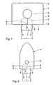
- the hernia mesh shown in FIG. 1 serves to supply a hiatal hernia. It has a base plate 1 of a conventional sheet-like, flexible mesh material, which is knitted from a monofilament polypropylene thread in Atlas lapping.
- the basis weight of the hernia mesh can be between 60 and 65 g / m 2 , but also significantly lower.
- the outer contour of the base plate 1 is substantially rectangular with rounded corner regions 2.
- a passage opening 3 is created, which serves in the case of the hiatal hernia network shown for the passage of the esophagus. Starting from this passage opening 3 extends to a longitudinal side 4 of the base plate 1 towards a straight insertion slot 5, which merges with a curved mouth 6 in this longitudinal side 4 at a central position.
- an integrally attached, substantially rectangular, bridge strap 7 is attached to the blank of the base plate 1.
- the corner regions 2 'of the bridge plate 7 are rounded.
- the width b of the bridge plate 7 corresponds to just under the length of the insertion slot 5. Their length 1 corresponds to about twice the width b.
- the shape of the base plate 1, the passage opening 3, the insertion slot 5 and the sewing bridge 7 shown in solid lines in FIG. 1 is made of a net web material with the aid of a laser cutting beam produced. Due to the laser cutting, the cutting edges are melted clean, so that no pieces of fiber threaten to escape from the hernia mesh.
- the hernia mesh When using the hernia mesh, it is pulled over the esophagus by opening the insertion slot 5 until it comes to lie in the passage opening 3.
- the base plate 1 is smoothly smoothed contiguous with the flanks of the insertion slot 5 and then the bridge tab 7 along the dotted, in alignment with the remaining longitudinal side 4 folding edge 8 turned inside, so that the insertion slot 5 to shortly before the passage opening 3 and in the longitudinal direction on both sides is covered substantially symmetrically.
- the bridge plate 7 is sewn to the underlying parts of the base plate 1 on both sides of the insertion slot 5, so that the slot 5 is stably closed.
- the hernia mesh illustrated in FIG. 2 serves to supply a inguinal hernia.
- Its base plate 1 ' is substantially arched, wherein in the lower, rectangular part of the passage opening 3 and the insertion slot 5 are created in the blank. The latter opens into the short transverse side 9 of the base plate 1 '.
- a bridge strap 7 is attached in one piece. After positioning the hernia mesh so that the spermatic cord passes through the passage opening 3, the insertion slot 5 can be closed as described with reference to Fig. 1 by flipping the bridge flap 7 along the fold edge 8 and stitching to the mutual areas along the slot flanks.
- the hernia net shown in Fig. 3 has over the embodiment shown in Fig. 1 on an enlarged bridge plate 7, which corresponds in length about the entire longitudinal side 4 of the base plate 1 "and in width about half the transverse side 9.
- a semicircular recess 10 in the bridge flap 7. an insertion slot 5 extending in the base plate 1 is again extending to one end of the bridge flap 7 " intended.
- FIG. 3 An enlargement of the bridge flap 7 analogous to FIG. 3 shows the hernia mesh according to FIG. 4. In that regard, reference may be made to further explanations for the description of FIG. 3.
- a closed double seam 12 placed between the folded flap portion 13 and the underlying net material of the blank 11 on a half side of the envelope.
- the positioning of the double seam 12 with an outer seam 14 and an inner seam 15 spaced inwardly therefrom is selected so that there is still room for the passage opening 3 and edge trimming of the blank 11.
- the production of the double seam 12 is indicated in phantom in FIG. 5B.
- separating cut 17 between the passage opening 3 and the folded edge 8 and along the folded edge 8 to the side facing away from the double seam 12.
- This punctured in Fig. 5D indicated separating cut 17 passes only through the base plate 1 "forming layer of the net material, but not by the flap portion 13, so that the left of the separating cut 17 for the insertion slot 5 lying flap of the flap portion 13 as before on the blank 11th gets stuck and after insertion of spermatic cord or esophagus over the insertion slot 5 formed by the separating cut 17 into the passage opening 3, a suturing of this flap 18 with the underlying part of the base plate 1 "can be made by the surgeon.
- the hernia nets according to FIGS. 1 to 4 are, moreover, provided with a continuous titanization covering the entire net surface after being cut from a sheet material by means of a PACVD process known from the prior art.
- This metallization process is for example from the DE 199 45 299 A known and leads to a titanium-containing coating having a thickness in the range of ⁇ 2 microns, preferably from 5 to 700 nm. Practical values of the coating thickness are 20 to 30 nm.
Landscapes
- Health & Medical Sciences (AREA)
- Heart & Thoracic Surgery (AREA)
- Life Sciences & Earth Sciences (AREA)
- Transplantation (AREA)
- Engineering & Computer Science (AREA)
- Biomedical Technology (AREA)
- Cardiology (AREA)
- Vascular Medicine (AREA)
- Oral & Maxillofacial Surgery (AREA)
- Animal Behavior & Ethology (AREA)
- General Health & Medical Sciences (AREA)
- Public Health (AREA)
- Veterinary Medicine (AREA)
- Prostheses (AREA)
- Pharmaceuticals Containing Other Organic And Inorganic Compounds (AREA)
Description
- Die Erfindung betrifft ein Herniennetz zur Versorgung von insbesondere Leisten- oder Hiatushernien mit den im Oberbegriff des Anspruches 1 angegebenen Merkmalen.
- Derartige Herniennetze sind hinsichtlich ihrer grundsätzlichen Konfiguration in der Medizintechnik üblich und Standardprodukte für die Hemienversorgung. Eine spezielle Weiterbildung auf der Basis dieser Grundkonfiguration ist beispielsweise der
WO 00/67663 A1 - Herniennetze werden bei der operativen Reparation von insbesondere Leistenhemien verwendet, um ein spannungsfreies Überdecken des Defektes zur Stabilisierung der Bauchwand zu erzielen. Je nach Art und Lage der Hernie kann es dabei notwendig sein, eine Körperröhre, wie beispielsweise den Samenstrang bei einer Leistenhernie oder die Speiseröhre bei einer Hiatushernie durch das Netz zu führen. Hierzu ist in der so bezeichneten Grundplatte aus einem lagenförmigen, flexiblen Netzmaterial eine Durchlassöffnung angelegt. Da die Körperröhre naturgemäß keinen in die Durchlassöffnung einfädelbaren Anfang besitzt, muss in der Grundplatte ein Einführungsschlitz zwischen dem äußeren Umriss der Grundplatte und der Durchlassöffnung zum Einführen der Körperröhre dorthin angelegt sein.
- In der herkömmlichen Operationstechnik wird dieser Schlitz nach dem Einführen der Körperröhre in die Durchlassöffnung geschlossen, indem die Schlitzflanken in eine Überlapp-Stellung gebracht und miteinander vernäht werden. Dieses Zusammenziehen sorgt allerdings für eine Deformation des Herniennetzes, was eine saubere Lage an der Bauchwand oder am Zwerchfell beeinträchtigen kann.
- Zur Lösung der vorstehenden Problematik ist es laut der
FR-A-2744906 - Problematisch bei diesem Stand der Technik ist die aufwendige Handhabung der separaten Nähbrücke, was einen zusätzlichen Herstellungsaufwand mit sich bringt. Die Erfindung schlägt daher laut kennzeichnungsteil des Anspruches 1 die einstückige Ausbildung der Nähbrücke aus dem Netzmaterial der Grundplatte von Dadurch erübrigt sich eine umständliche Handhabung kleinflächiger Netzteile zum Zuschneiden und Fixieren an dem eigentlichen Herniennetz.
- Weitere bevorzugte Ausbildungen eines solchen Herniennetzes sind in den Unteransprüchen angegeben. Merkmale, Einzelheiten und Vorteile der Erfindung ergeben sich ferner aus der nachfolgenden Beschreibung, in der Ausführungsbeispiele anhand der beigefügten Zeichnungen näher erläutert werden. Es zeigen:
- Fig. 1
- eine Draufsicht auf ein Herniennetz für eine Hiatushernie,
- Fig. 2
- eine Draufsicht auf ein Herniennetz für eine Leistenhernie,
- Fig. 3 und 4
- Draufsichten auf Herniennetze für eine Hiatus- beziehungsweise Leistenhernie in einer zu den Fig. 1 beziehungsweise 2 alternativen Ausführungsform, und
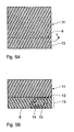
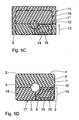
- Fig. 5A-D
- eine schematische Abfolge von Herstellungsschritten für das Herniennetz gemäß Fig. 3.
- Das in Fig. 1 gezeigte Herniennetz dient zur Versorgung einer Hiatushernie. Es weist eine Grundplatte 1 aus einem üblichen lagenförmigen, flexiblen Netzmaterial auf, das aus einem monofilen Polypropylen-Faden in Atlas-Legung gewirkt ist. Das Flächengewicht des Herniennetzes kann zwischen 60 und 65 g/m2 betragen, aber auch deutlich darunter liegen.
- Die äußere Umrissform der Grundplatte 1 ist im Wesentlichen rechteckig mit abgerundeten Eckbereichen 2. Zentral ist eine Durchlassöffnung 3 angelegt, die im Falle des gezeigten Hiatus-Herniennetzes zur Durchführung der Speiseröhre dient. Ausgehend von dieser Durchlassöffnung 3 verläuft zur einen Längsseite 4 der Grundplatte 1 hin ein gerader Einführungsschlitz 5, der mit einer gebogenen Mündung 6 in diese Längsseite 4 an zentraler Position übergeht. Auf einer Seite neben der Mündung 6 ist an der Längsseite 4 der Grundplatte 1 eine einstückig angesetzte, im Wesentlichen etwa rechteckförmige Brückenlasche 7 an den Zuschnitt der Grundplatte 1 angehängt. Auch die Eckbereiche 2' der Brückenlasche 7 sind abgerundet. Die Breite b der Brückenlasche 7 entspricht knapp der Länge des Einführungsschlitzes 5. Ihre Länge 1 entspricht etwa der doppelten Breite b.
- Die in Fig. 1 mit durchgezogenen Linien dargestellte Form der Grundplatte 1, der Durchlassöffnung 3, des Einführungsschlitzes 5 und der Nähbrücke 7 wird mit Hilfe eines Laser-Schneidstrahls aus einem Netz-Bahnmaterial hergestellt. Durch das Laserschneiden sind die Schneidkanten sauber abgeschmolzen, sodass keine Faserstücke aus dem Herniennetz auszutreten drohen.
- Beim Einsatz des Herniennetzes wird es durch Öffnen des Einführungsschlitzes 5 über die Speiseröhre gezogen, bis diese in der Durchlassöffnung 3 zu liegen kommt. Die Grundplatte 1 wird mit den Flanken des Einführungsschlitzes 5 sauber aneinanderliegend geglättet und anschließend die Brückenlasche 7 entlang der punktierten, in der Flucht der verbleibenden Längsseite 4 liegenden Faltkante 8 nach innen umgeschlagen, sodass der Einführungsschlitz 5 bis kurz vor der Durchlassöffnung 3 und in Längsrichtung beiderseits im Wesentlichen symmetrisch überdeckt wird. Anschließend werden - wie nicht näher dargestellt ist - die Brückenlasche 7 mit den darunter befindlichen Teilen der Grundplatte 1 beiderseits des Einführungsschlitzes 5 vernäht, sodass der Schlitz 5 stabil geschlossen ist.
- Das in Fig. 2 dargestellte Herniennetz dient zur Versorgung einer Leistenhernie. Seine Grundplatte 1' ist im Wesentlichen torbogenförmig, wobei im unteren, rechteckigen Teil die Durchlassöffnung 3 und der Einführungsschlitz 5 im Zuschnitt angelegt sind. Letzterer mündet in die kurze Querseite 9 der Grundplatte 1'. Analog der Ausführungsform gemäß Fig. 1 ist wiederum anschließend an die Mündung 6 des Schlitzes 5 eine Brückenlasche 7 einstückig angesetzt. Nach dem Positionieren des Herniennetzes so, dass der Samenstrang durch die Durchlassöffnung 3 verläuft, kann der Einführungsschlitz 5 wie anhand von Fig. 1 beschrieben durch Umlegen der Brückenlasche 7 entlang der Faltkante 8 und Vernähen mit den beiderseitigen Bereichen entlang der Schlitzflanken geschlossen werden.
- Das in Fig. 3 dargestellte Herniennetz weist gegenüber der in Fig. 1 gezeigten Ausführungsform eine vergrößerte Brückenlasche 7 auf, die in ihrer Länge etwa der gesamten Längsseite 4 der Grundplatte 1" und in ihrer Breite etwa der halben Querseite 9 entspricht. Beim Einklappen der Brückenlasche 7 um die Faltkante 8 kommt sie im Bereich der Durchlassöffnung 3 zu liegen. Diesem Umstand wird durch eine halbkreisförmige Aussparung 10 in der Brückenlasche 7 Rechnung getragen. Im Übrigen ist wieder ein sich bis zum einen Ende der Brückenlasche 7 erstreckender Einführungsschlitz 5 in der Grundplatte 1" vorgesehen.
- Eine zu Fig. 3 analoge Vergrößerung der Brückenlasche 7 zeigt das Herniennetz gemäß Fig. 4. Insoweit kann zu weiteren Ausführungen auf die Beschreibung der Fig. 3 verwiesen werden.
- Ein weiterer Unterschied zum Ausführungsbeispiel gemäß Fig. 2 besteht in der Grundform der Grundplatte 1"', die hier wieder im Wesentlichen rechteckig ist.
- Anhand der Fig. 5A bis D wird nun die konstruktiv einfachen und geschickte Herstellung des in Fig. 3 gezeigten Hemiennetzes erläutert.
- Es wird ausgegangen von einem rechteckigen Zuschnitt 11 des eingangs erwähnten Netzmaterials aus Polypropylen. Dieser Zuschnitt wird in einem ersten Schritt entlang einer strichliert gezeigten Falt-Linie 8 gefaltet (Pfeil F), die die Breite des Zuschnittes 11 im Verhältnis von etwas mehr als 2:1 teilt (Fig. 5A).
- Anschließend wird mit Hilfe eines Polypropylen-Fadens, der dem Fadenmaterial des Zuschnittes 11 entspricht, eine geschlossene Doppelnaht 12 zwischen dem umgefalteten Laschenteil 13 und dem darunter befindlichen Netzmaterial des Zuschnittes 11 auf einer Halbseite des Umschlages angelegt. Die Positionierung der Doppelnaht 12 mit einer äußeren Naht 14 und einer mit Abstand davon nach innen versetzten inneren Naht 15 ist so gewählt, dass noch Platz für die Durchlassöffnung 3 und eine Randbesäumung des Zuschnittes 11 verbleibt. Das Herstellen der Doppelnaht 12 ist in Fig. 5B strichpunktiert angedeutet.
- In einem nächsten Fertigungsschritt gemäß Fig. 5C wird- wie bereits angesprochen - durch Lasern oder Stanzen die eigentliche Kontur der Grundplatte 1" aus dem Zuschnitt 11 mit umgeklappten Laschenteil 13 herausgearbeitet, wie dies lang-strichliert angedeutet ist. Dabei ist darauf zu achten, dass die umlaufende, gegenüber dem Zuschnitt 1 etwas verkleinerte und in den Ecken abgerundete Laser- beziehungsweise Stanz-Schnittlinie 16 die Faltkante 8 zwischen Laschenteil 13 und Grundplatte 1" unversehrt lässt (Fig. 5C).
- Das so herausgearbeitete Herniennetz wird noch durch einen Trennschnitt 17 zwischen Durchlassöffnung 3 und Faltkante 8 sowie entlang der Faltkante 8 zu der der Doppelnaht 12 abgewandten Seite hin komplettiert. Dieser in Fig. 5D punktiert angedeutete Trennschnitt 17 geht nur durch die die Grundplatte 1" bildende Lage des Netzmaterials, nicht jedoch durch das Laschenteil 13, sodass der links vom Trennschnitt 17 für den Einführungsschlitz 5 liegende Lappen des Laschenteils 13 nach wie vor am Zuschnitt 11 hängenbleibt und nach dem Einführen von Samenstrang oder Speiseröhre über den durch den Trennschnitt 17 gebildeten Einführungsschlitz 5 in die Durchlassöffnung 3 ein Vernähen dieses Lappens 18 mit dem darunter befindlichen Teil der Grundplatte 1" durch den Chirurgen vorgenommen werden kann.
- Die Herniennetze gemäß den Fig. 1 bis 4 werden im Übrigen nach dem Zuschneiden aus einem Bahnmaterial mittels eines aus dem Stand der Technik bekannten PACVD-Prozesses mit einer die gesamte Netzoberfläche bedeckenden, durchgehenden Titanisierung versehen. Dieser Metallisierungsprozess ist beispielsweise aus der
DE 199 45 299 A bekannt und führt zu einer titanhaltigen Beschichtung einer Dicke im Bereich von < 2 µm, vorzugsweise von 5 bis 700 nm. Praktische Werte der Beschichtungsdicke liegen bei 20 bis 30 nm.
Claims (10)
- Herniennetz zur Versorgung von insbesondere Leisten- oder Hiatushernien, umfassend- eine Grundplatte (1, 1', 1", 1"') aus einem lagenförmigen, flexiblen Netzmaterial,- eine Durchlassöffnung (3) in der Grundplatte (1, 1', 1'', 1''') für eine Körperröhre, insbesondere für den Samenstrang oder die Speiseröhre,- einen Einführungsschlitz (5) zwischen dem Umriss (4, 9) der Grundplatte (1, 1', 1", 1"') und der Durchlassöffnung (3) zum Einführen der Körperröhre in die Durchlassöffnung (3), und- eine im Bereich der Mündung (6) des Einführungsschlitzes (5) liegende Nähbrücke (7), die über den Einführungsschlitz (5) klappbar und beiderseits davon mit dem Netzmaterial der Grundplatte (1, 1', 1",1'") vernähbar ist, dadurch gekennzeichnet, dass die Nähbrücke als einstückig mit dem Netzmaterial der Grundplatte (1, 1', 1", 1"') zugeschnittene Brückenlasche (7) ausgebildet ist.
- Herniennetz nach Anspruch 1, dadurch gekennzeichnet, dass die Brückenlasche (7) eine rechteckige Grundform mit einer solchen Dimensionierung aufweist, dass in ihrem umgeklappten Zustand der Einführungsschlitz (5) bis mindestens kurz vor der Durchlassöffnung (3) überdeckt ist.
- Herniennetz nach Anspruch 1 oder 2, dadurch gekennzeichnet, dass die Brückenlasche (7) den Einführungsschlitz (5) beiderseits im Wesentlichen symmetrisch überdeckt.
- Herniennetz nach einem der Ansprüche 1 bis 3, dadurch gekennzeichnet, dass die Brückenlasche (7) unmittelbar anschließend an die Mündung (6) des Einführungsschlitzes (5) in die Umrisskante (4, 9) der Grundplatte (1, 1', 1'', 1''') einstückig an die Grundplatte (1,1', 1'', 1''') angesetzt ist.
- Herniennetz nach einem der vorgenannten Ansprüche, dadurch gekennzeichnet, dass die Grundplatte (1, 1', 1'', 1''') und/oder die Brückenlasche (7) abgerundete Eckbereiche (2, 2') aufweisen.
- Herniennetz nach einem der vorgenannten Ansprüche, dadurch gekennzeichnet, dass es aus einem Netz-Bahnmaterial vorzugsweise aus Polypropylen mit Hilfe eines Laser-Schneidstrahls zugeschnitten ist.
- Herniennetz nach einem der vorgenannten Ansprüche, gekennzeichnet durch eine metallhaltige, durchgehende, körperverträgliche Beschichtung.
- Herniennetz nach Anspruch 7, dadurch gekennzeichnet, dass die Beschichtung eine Titan-haltige Beschichtung mit einer Dicke von kleiner 2 µm, vorzugsweise von 5 bis 700 nm ist.
- Herniennetz nach einem der vorgenannten Ansprüche, dadurch gekennzeichnet, dass die Brückenlasche (7) in einem Vorkonfektionierungszustand umgeklappt und auf einer Seite des Einführungsschlitzes (5) mit dem Netzmaterial der Grundplatte (1, 1', 1", 1"') vernäht ist.
- Herniennetz nach Anspruch 9, dadurch gekennzeichnet, dass die einseitige Vernähung als Doppelnaht (12) mit einer äußeren Naht (14) und einer mit Abstand davon nach innen versetzten Naht (15) angelegt ist.
Applications Claiming Priority (2)
| Application Number | Priority Date | Filing Date | Title |
|---|---|---|---|
| DE102004009894A DE102004009894A1 (de) | 2004-02-26 | 2004-02-26 | Herniennetz zur Versorgung von Leisten- und Hiatushernien |
| PCT/EP2005/002029 WO2005082274A1 (de) | 2004-02-26 | 2005-02-25 | Herniennetz zur versorgung von leisten-oder hiatushernien |
Publications (2)
| Publication Number | Publication Date |
|---|---|
| EP1718240A1 EP1718240A1 (de) | 2006-11-08 |
| EP1718240B1 true EP1718240B1 (de) | 2007-07-04 |
Family
ID=34853859
Family Applications (1)
| Application Number | Title | Priority Date | Filing Date |
|---|---|---|---|
| EP05707636A Expired - Lifetime EP1718240B1 (de) | 2004-02-26 | 2005-02-25 | Herniennetz zur versorgung von leisten- oder hiatushernien |
Country Status (6)
| Country | Link |
|---|---|
| US (1) | US20080243149A1 (de) |
| EP (1) | EP1718240B1 (de) |
| AT (1) | ATE366092T1 (de) |
| DE (2) | DE102004009894A1 (de) |
| ES (1) | ES2287899T3 (de) |
| WO (1) | WO2005082274A1 (de) |
Families Citing this family (28)
| Publication number | Priority date | Publication date | Assignee | Title |
|---|---|---|---|---|
| RU2303403C1 (ru) * | 2005-10-31 | 2007-07-27 | Евгений Сергеевич Петров | Способ безнатяжной комбинированной пластики пахового канала по петрову-кошеву |
| US8795384B2 (en) * | 2007-01-10 | 2014-08-05 | Cook Biotech Incorporated | Implantable devices useful for reinforcing a surgically created stoma |
| US8317808B2 (en) | 2008-02-18 | 2012-11-27 | Covidien Lp | Device and method for rolling and inserting a prosthetic patch into a body cavity |
| US9044235B2 (en) | 2008-02-18 | 2015-06-02 | Covidien Lp | Magnetic clip for implant deployment device |
| US8808314B2 (en) | 2008-02-18 | 2014-08-19 | Covidien Lp | Device and method for deploying and attaching an implant to a biological tissue |
| US9833240B2 (en) | 2008-02-18 | 2017-12-05 | Covidien Lp | Lock bar spring and clip for implant deployment device |
| US9301826B2 (en) | 2008-02-18 | 2016-04-05 | Covidien Lp | Lock bar spring and clip for implant deployment device |
| CA2715740C (en) | 2008-02-18 | 2014-05-27 | Polytouch Medical Ltd. | A device and method for deploying and attaching a patch to a biological tissue |
| US9398944B2 (en) | 2008-02-18 | 2016-07-26 | Covidien Lp | Lock bar spring and clip for implant deployment device |
| US9034002B2 (en) | 2008-02-18 | 2015-05-19 | Covidien Lp | Lock bar spring and clip for implant deployment device |
| US9393093B2 (en) | 2008-02-18 | 2016-07-19 | Covidien Lp | Clip for implant deployment device |
| US9393002B2 (en) | 2008-02-18 | 2016-07-19 | Covidien Lp | Clip for implant deployment device |
| US8758373B2 (en) | 2008-02-18 | 2014-06-24 | Covidien Lp | Means and method for reversibly connecting a patch to a patch deployment device |
| AU2009305958B9 (en) | 2008-10-20 | 2013-07-11 | Covidien Lp | A device for attaching a patch to a biological tissue |
| AU2010245983B2 (en) * | 2009-05-07 | 2015-07-02 | Covidien Lp | Surgical patch cover and method of use |
| CA2769666C (en) | 2009-08-17 | 2018-02-13 | Arie Levy | Means and method for reversibly connecting an implant to a deployment device |
| WO2011021083A1 (en) | 2009-08-17 | 2011-02-24 | PolyTouch Medical, Inc. | Articulating patch deployment device and method of use |
| KR20090130277A (ko) * | 2009-11-29 | 2009-12-22 | 이정삼 | 단일공을 통한 복강경하 탈장수술에 이용되는 특수 인공막 |
| GB201113303D0 (en) * | 2011-08-02 | 2011-09-14 | Xiros Ltd | Connective tissue repair pad |
| FR2985170B1 (fr) * | 2011-12-29 | 2014-01-24 | Sofradim Production | Prothese pour hernie inguinale |
| EA031521B1 (ru) * | 2012-03-26 | 2019-01-31 | Пфм Медикал, Инк. | Биологически совместимый сетчатый имплант |
| US9820839B2 (en) | 2012-04-10 | 2017-11-21 | Ethicon, Inc. | Single plane tissue repair patch having a locating structure |
| US9820837B2 (en) | 2012-04-10 | 2017-11-21 | Ethicon, Inc. | Single plane tissue repair patch |
| US9820838B2 (en) | 2012-04-10 | 2017-11-21 | Ethicon, Inc. | Single plane tissue repair patch |
| US8603117B2 (en) | 2012-04-23 | 2013-12-10 | Conform, LLC | Prosthetic mesh for laparoscopic repair of inguinal hernia |
| GB201301784D0 (en) | 2013-02-01 | 2013-03-20 | Xiros Ltd | Connective tissue repair technology |
| CA2972008C (en) | 2014-12-24 | 2020-08-11 | C.R. Bard, Inc. | Implantable prosthesis for soft tissue repair |
| WO2016154478A1 (en) | 2015-03-24 | 2016-09-29 | Hexagon Health, Inc. | Gender-specific mesh implant with barrier for inguinal hernia repair |
Family Cites Families (12)
| Publication number | Priority date | Publication date | Assignee | Title |
|---|---|---|---|---|
| GB9415125D0 (en) * | 1994-07-27 | 1994-09-14 | Notaras Mitchell J | Surgical product and its use |
| FR2728776B1 (fr) * | 1994-12-30 | 1997-07-18 | Cogent Sarl | Element prothetique pour le traitement des hernies de l'aine, notamment par voie coelioscopique |
| FR2744906B1 (fr) * | 1996-02-21 | 1998-04-24 | Cousin Biotech | Plaque de refection de hernie |
| US5716409A (en) * | 1996-10-16 | 1998-02-10 | Debbas; Elie | Reinforcement sheet for use in surgical repair |
| DE19832634A1 (de) * | 1998-07-09 | 2000-01-13 | Ethicon Endo Surgery Europe | Mehrschichtiges flächiges Implantat |
| DE19945299A1 (de) * | 1999-09-22 | 2001-03-29 | Gfe Met & Mat Gmbh | Plasmabeschichtungsverfahren und dreidimensionales Kunststoffsubstrat mit einer metallhaltigen Beschichtung auf der Kunststoffoberfläche |
| AU2001245671B8 (en) * | 2000-03-10 | 2006-06-01 | Mast Biosurgery Ag | Resorbable micro-membrane for attenuation of scar tissue |
| FR2807936B1 (fr) * | 2000-04-20 | 2002-08-02 | Sofradim Production | Renfort de paroi abdominale pour le traitement des hernies inguinales par voie anterieure sans tension |
| FR2807937B1 (fr) * | 2000-04-20 | 2002-08-02 | Sofradim Production | Tricot prothetique agrippant, son procede de fabrication et implant de renfort pour le traitement des deficits parietaux |
| IT1318499B1 (it) * | 2000-05-05 | 2003-08-25 | Angiologica B M S R L | Rete anatomica a doppio strato per chirurgia. |
| US6551356B2 (en) * | 2001-03-19 | 2003-04-22 | Ethicon, Inc. | Pocketed hernia repair |
| US6736823B2 (en) * | 2002-05-10 | 2004-05-18 | C.R. Bard, Inc. | Prosthetic repair fabric |
-
2004
- 2004-02-26 DE DE102004009894A patent/DE102004009894A1/de not_active Withdrawn
-
2005
- 2005-02-25 AT AT05707636T patent/ATE366092T1/de not_active IP Right Cessation
- 2005-02-25 EP EP05707636A patent/EP1718240B1/de not_active Expired - Lifetime
- 2005-02-25 US US10/598,047 patent/US20080243149A1/en not_active Abandoned
- 2005-02-25 ES ES05707636T patent/ES2287899T3/es not_active Expired - Lifetime
- 2005-02-25 DE DE502005000981T patent/DE502005000981D1/de not_active Expired - Lifetime
- 2005-02-25 WO PCT/EP2005/002029 patent/WO2005082274A1/de not_active Ceased
Non-Patent Citations (1)
| Title |
|---|
| None * |
Also Published As
| Publication number | Publication date |
|---|---|
| DE102004009894A1 (de) | 2005-09-15 |
| EP1718240A1 (de) | 2006-11-08 |
| ES2287899T3 (es) | 2007-12-16 |
| WO2005082274A1 (de) | 2005-09-09 |
| ATE366092T1 (de) | 2007-07-15 |
| DE502005000981D1 (de) | 2007-08-16 |
| US20080243149A1 (en) | 2008-10-02 |
Similar Documents
| Publication | Publication Date | Title |
|---|---|---|
| WO2005082274A1 (de) | Herniennetz zur versorgung von leisten-oder hiatushernien | |
| DE69413718T2 (de) | Chirurgisches netzwerk mit halbsteifen grenzelementen | |
| EP1673030B1 (de) | Flächiges netzimplantat zur hernienversorgung | |
| DE10120942B4 (de) | Abdominalwand-Verstärkung | |
| DE60117266T2 (de) | Aus einer doppelschicht bestehendes anatomisches netz für die chirurgie | |
| DE69522425T2 (de) | Protheseelement für die Behandlung von Leistenbrüchen, insbesondere für die Coelioskopie | |
| DE60219528T2 (de) | Implantierbare prothese | |
| DE60200984T2 (de) | Prothese zur Herniereparatur und ihre Herstellungsverfahren | |
| DE60212006T2 (de) | Vaskuläres Schutzsystem und Angioplastievorrichtung | |
| DE60006361T2 (de) | Mehrschichtige prothese zur chirurgischen behandlung von inguinalhernia | |
| DE69532556T2 (de) | Doppelschichtige dynamische prothese zur chirurgischen behandlung der inguinalhernia | |
| EP0264952B1 (de) | Verfahren zum Herstellen von auf dem Körper zu tragenden Artikeln | |
| DE69801447T2 (de) | Prothesenimplantat zum verschliessen von körperkanälen sowie mit diesem implantat ausgestattete verschlusseinheit | |
| DE60126172T2 (de) | Prothese für Herniereparatur | |
| DE60107270T2 (de) | Implantierbare prothese | |
| DE60115243T2 (de) | Implantierbare prothese | |
| DE102005004317B3 (de) | Gewebeverbinder und Verfahren zur Herstellung | |
| DE102013004486A1 (de) | Chirurgisches Implantat | |
| DE102012021547A1 (de) | Chirurgisches Implantat | |
| DE102012016090A1 (de) | Chirurgisches Implantat | |
| DE102010008360A1 (de) | Medizinisches Implantat, in welchem beim Crimpen bzw. Falten Lücken verbleiben, Verfahren und Einrichtung zum Verbringen | |
| DE102008013381A1 (de) | Stent, welcher vom expandierten Zustand kontrolliert erneut im Durchmesser verringerbar ist | |
| EP4201377B1 (de) | Embolieschutzvorrichtung, verfahren zu deren faltung und formvorrichtung | |
| DE60315501T2 (de) | Anatomisches verstärkungsimplantat für die bauchwand zur behandlung einer inguinalhernie | |
| EP1455688B1 (de) | Gefässprothese, insbesondere zum ersatz von herznahen bereichen der aorta |
Legal Events
| Date | Code | Title | Description |
|---|---|---|---|
| PUAI | Public reference made under article 153(3) epc to a published international application that has entered the european phase |
Free format text: ORIGINAL CODE: 0009012 |
|
| 17P | Request for examination filed |
Effective date: 20060415 |
|
| AK | Designated contracting states |
Kind code of ref document: A1 Designated state(s): AT BE BG CH CY CZ DE DK EE ES FI FR GB GR HU IE IS IT LI LT LU MC NL PL PT RO SE SI SK TR |
|
| RIN1 | Information on inventor provided before grant (corrected) |
Inventor name: HEINLEIN, MARKUS Inventor name: ZIMMERMANN, HANNGOERG Inventor name: KOECKERLING, FERDINAND |
|
| GRAP | Despatch of communication of intention to grant a patent |
Free format text: ORIGINAL CODE: EPIDOSNIGR1 |
|
| DAX | Request for extension of the european patent (deleted) | ||
| GRAS | Grant fee paid |
Free format text: ORIGINAL CODE: EPIDOSNIGR3 |
|
| GRAA | (expected) grant |
Free format text: ORIGINAL CODE: 0009210 |
|
| AK | Designated contracting states |
Kind code of ref document: B1 Designated state(s): AT BE BG CH CY CZ DE DK EE ES FI FR GB GR HU IE IS IT LI LT LU MC NL PL PT RO SE SI SK TR |
|
| REG | Reference to a national code |
Ref country code: GB Ref legal event code: FG4D Free format text: NOT ENGLISH |
|
| REG | Reference to a national code |
Ref country code: CH Ref legal event code: EP |
|
| GBT | Gb: translation of ep patent filed (gb section 77(6)(a)/1977) |
Effective date: 20070705 |
|
| REG | Reference to a national code |
Ref country code: IE Ref legal event code: FG4D Free format text: LANGUAGE OF EP DOCUMENT: GERMAN |
|
| REF | Corresponds to: |
Ref document number: 502005000981 Country of ref document: DE Date of ref document: 20070816 Kind code of ref document: P |
|
| ET | Fr: translation filed | ||
| REG | Reference to a national code |
Ref country code: ES Ref legal event code: FG2A Ref document number: 2287899 Country of ref document: ES Kind code of ref document: T3 |
|
| NLV1 | Nl: lapsed or annulled due to failure to fulfill the requirements of art. 29p and 29m of the patents act | ||
| PG25 | Lapsed in a contracting state [announced via postgrant information from national office to epo] |
Ref country code: LT Free format text: LAPSE BECAUSE OF FAILURE TO SUBMIT A TRANSLATION OF THE DESCRIPTION OR TO PAY THE FEE WITHIN THE PRESCRIBED TIME-LIMIT Effective date: 20070704 Ref country code: BG Free format text: LAPSE BECAUSE OF FAILURE TO SUBMIT A TRANSLATION OF THE DESCRIPTION OR TO PAY THE FEE WITHIN THE PRESCRIBED TIME-LIMIT Effective date: 20071004 Ref country code: FI Free format text: LAPSE BECAUSE OF FAILURE TO SUBMIT A TRANSLATION OF THE DESCRIPTION OR TO PAY THE FEE WITHIN THE PRESCRIBED TIME-LIMIT Effective date: 20070704 Ref country code: IS Free format text: LAPSE BECAUSE OF FAILURE TO SUBMIT A TRANSLATION OF THE DESCRIPTION OR TO PAY THE FEE WITHIN THE PRESCRIBED TIME-LIMIT Effective date: 20071104 Ref country code: PT Free format text: LAPSE BECAUSE OF FAILURE TO SUBMIT A TRANSLATION OF THE DESCRIPTION OR TO PAY THE FEE WITHIN THE PRESCRIBED TIME-LIMIT Effective date: 20071204 Ref country code: SI Free format text: LAPSE BECAUSE OF FAILURE TO SUBMIT A TRANSLATION OF THE DESCRIPTION OR TO PAY THE FEE WITHIN THE PRESCRIBED TIME-LIMIT Effective date: 20070704 Ref country code: NL Free format text: LAPSE BECAUSE OF FAILURE TO SUBMIT A TRANSLATION OF THE DESCRIPTION OR TO PAY THE FEE WITHIN THE PRESCRIBED TIME-LIMIT Effective date: 20070704 |
|
| PG25 | Lapsed in a contracting state [announced via postgrant information from national office to epo] |
Ref country code: PL Free format text: LAPSE BECAUSE OF FAILURE TO SUBMIT A TRANSLATION OF THE DESCRIPTION OR TO PAY THE FEE WITHIN THE PRESCRIBED TIME-LIMIT Effective date: 20070704 |
|
| REG | Reference to a national code |
Ref country code: IE Ref legal event code: FD4D |
|
| PG25 | Lapsed in a contracting state [announced via postgrant information from national office to epo] |
Ref country code: DK Free format text: LAPSE BECAUSE OF FAILURE TO SUBMIT A TRANSLATION OF THE DESCRIPTION OR TO PAY THE FEE WITHIN THE PRESCRIBED TIME-LIMIT Effective date: 20070704 Ref country code: GR Free format text: LAPSE BECAUSE OF FAILURE TO SUBMIT A TRANSLATION OF THE DESCRIPTION OR TO PAY THE FEE WITHIN THE PRESCRIBED TIME-LIMIT Effective date: 20071005 |
|
| PLBE | No opposition filed within time limit |
Free format text: ORIGINAL CODE: 0009261 |
|
| STAA | Information on the status of an ep patent application or granted ep patent |
Free format text: STATUS: NO OPPOSITION FILED WITHIN TIME LIMIT |
|
| PG25 | Lapsed in a contracting state [announced via postgrant information from national office to epo] |
Ref country code: SK Free format text: LAPSE BECAUSE OF FAILURE TO SUBMIT A TRANSLATION OF THE DESCRIPTION OR TO PAY THE FEE WITHIN THE PRESCRIBED TIME-LIMIT Effective date: 20070704 Ref country code: IE Free format text: LAPSE BECAUSE OF FAILURE TO SUBMIT A TRANSLATION OF THE DESCRIPTION OR TO PAY THE FEE WITHIN THE PRESCRIBED TIME-LIMIT Effective date: 20070704 Ref country code: CZ Free format text: LAPSE BECAUSE OF FAILURE TO SUBMIT A TRANSLATION OF THE DESCRIPTION OR TO PAY THE FEE WITHIN THE PRESCRIBED TIME-LIMIT Effective date: 20070704 |
|
| 26N | No opposition filed |
Effective date: 20080407 |
|
| PG25 | Lapsed in a contracting state [announced via postgrant information from national office to epo] |
Ref country code: RO Free format text: LAPSE BECAUSE OF FAILURE TO SUBMIT A TRANSLATION OF THE DESCRIPTION OR TO PAY THE FEE WITHIN THE PRESCRIBED TIME-LIMIT Effective date: 20070704 Ref country code: SE Free format text: LAPSE BECAUSE OF FAILURE TO SUBMIT A TRANSLATION OF THE DESCRIPTION OR TO PAY THE FEE WITHIN THE PRESCRIBED TIME-LIMIT Effective date: 20071004 |
|
| BERE | Be: lapsed |
Owner name: GFE MEDIZINTECHNIK G.M.B.H. Effective date: 20080228 |
|
| PG25 | Lapsed in a contracting state [announced via postgrant information from national office to epo] |
Ref country code: MC Free format text: LAPSE BECAUSE OF NON-PAYMENT OF DUE FEES Effective date: 20080228 |
|
| PG25 | Lapsed in a contracting state [announced via postgrant information from national office to epo] |
Ref country code: EE Free format text: LAPSE BECAUSE OF FAILURE TO SUBMIT A TRANSLATION OF THE DESCRIPTION OR TO PAY THE FEE WITHIN THE PRESCRIBED TIME-LIMIT Effective date: 20070704 |
|
| PG25 | Lapsed in a contracting state [announced via postgrant information from national office to epo] |
Ref country code: BE Free format text: LAPSE BECAUSE OF NON-PAYMENT OF DUE FEES Effective date: 20080228 |
|
| PG25 | Lapsed in a contracting state [announced via postgrant information from national office to epo] |
Ref country code: AT Free format text: LAPSE BECAUSE OF NON-PAYMENT OF DUE FEES Effective date: 20080225 |
|
| PG25 | Lapsed in a contracting state [announced via postgrant information from national office to epo] |
Ref country code: CY Free format text: LAPSE BECAUSE OF FAILURE TO SUBMIT A TRANSLATION OF THE DESCRIPTION OR TO PAY THE FEE WITHIN THE PRESCRIBED TIME-LIMIT Effective date: 20070704 |
|
| PG25 | Lapsed in a contracting state [announced via postgrant information from national office to epo] |
Ref country code: HU Free format text: LAPSE BECAUSE OF FAILURE TO SUBMIT A TRANSLATION OF THE DESCRIPTION OR TO PAY THE FEE WITHIN THE PRESCRIBED TIME-LIMIT Effective date: 20080105 Ref country code: LU Free format text: LAPSE BECAUSE OF NON-PAYMENT OF DUE FEES Effective date: 20080225 |
|
| PG25 | Lapsed in a contracting state [announced via postgrant information from national office to epo] |
Ref country code: TR Free format text: LAPSE BECAUSE OF FAILURE TO SUBMIT A TRANSLATION OF THE DESCRIPTION OR TO PAY THE FEE WITHIN THE PRESCRIBED TIME-LIMIT Effective date: 20070704 |
|
| REG | Reference to a national code |
Ref country code: CH Ref legal event code: PFA Owner name: PFM MEDICAL TITANIUM GMBH Free format text: GFE MEDIZINTECHNIK GMBH#HOEFENER STRASSE 45#90431 NUERNBERG (DE) -TRANSFER TO- PFM MEDICAL TITANIUM GMBH#HOEFENER STRASSE 45#90431 NUERNBERG (DE) |
|
| REG | Reference to a national code |
Ref country code: FR Ref legal event code: CD |
|
| REG | Reference to a national code |
Ref country code: ES Ref legal event code: PC2A Owner name: PFM MEDICAL TITANIUM GMBH Effective date: 20110318 |
|
| REG | Reference to a national code |
Ref country code: FR Ref legal event code: PLFP Year of fee payment: 12 |
|
| REG | Reference to a national code |
Ref country code: FR Ref legal event code: PLFP Year of fee payment: 13 |
|
| REG | Reference to a national code |
Ref country code: FR Ref legal event code: PLFP Year of fee payment: 14 |
|
| PGFP | Annual fee paid to national office [announced via postgrant information from national office to epo] |
Ref country code: FR Payment date: 20230220 Year of fee payment: 19 Ref country code: ES Payment date: 20230317 Year of fee payment: 19 Ref country code: CH Payment date: 20230307 Year of fee payment: 19 |
|
| PGFP | Annual fee paid to national office [announced via postgrant information from national office to epo] |
Ref country code: IT Payment date: 20230228 Year of fee payment: 19 Ref country code: GB Payment date: 20230221 Year of fee payment: 19 |
|
| PGFP | Annual fee paid to national office [announced via postgrant information from national office to epo] |
Ref country code: DE Payment date: 20230420 Year of fee payment: 19 |
|
| REG | Reference to a national code |
Ref country code: DE Ref legal event code: R119 Ref document number: 502005000981 Country of ref document: DE |
|
| REG | Reference to a national code |
Ref country code: CH Ref legal event code: PL |
|
| PG25 | Lapsed in a contracting state [announced via postgrant information from national office to epo] |
Ref country code: CH Free format text: LAPSE BECAUSE OF NON-PAYMENT OF DUE FEES Effective date: 20240229 |
|
| GBPC | Gb: european patent ceased through non-payment of renewal fee |
Effective date: 20240225 |
|
| PG25 | Lapsed in a contracting state [announced via postgrant information from national office to epo] |
Ref country code: CH Free format text: LAPSE BECAUSE OF NON-PAYMENT OF DUE FEES Effective date: 20240229 |
|
| PG25 | Lapsed in a contracting state [announced via postgrant information from national office to epo] |
Ref country code: DE Free format text: LAPSE BECAUSE OF NON-PAYMENT OF DUE FEES Effective date: 20240903 |
|
| PG25 | Lapsed in a contracting state [announced via postgrant information from national office to epo] |
Ref country code: GB Free format text: LAPSE BECAUSE OF NON-PAYMENT OF DUE FEES Effective date: 20240225 |
|
| PG25 | Lapsed in a contracting state [announced via postgrant information from national office to epo] |
Ref country code: FR Free format text: LAPSE BECAUSE OF NON-PAYMENT OF DUE FEES Effective date: 20240229 |
|
| PG25 | Lapsed in a contracting state [announced via postgrant information from national office to epo] |
Ref country code: GB Free format text: LAPSE BECAUSE OF NON-PAYMENT OF DUE FEES Effective date: 20240225 Ref country code: FR Free format text: LAPSE BECAUSE OF NON-PAYMENT OF DUE FEES Effective date: 20240229 Ref country code: DE Free format text: LAPSE BECAUSE OF NON-PAYMENT OF DUE FEES Effective date: 20240903 |
|
| PG25 | Lapsed in a contracting state [announced via postgrant information from national office to epo] |
Ref country code: IT Free format text: LAPSE BECAUSE OF NON-PAYMENT OF DUE FEES Effective date: 20240225 |
|
| REG | Reference to a national code |
Ref country code: ES Ref legal event code: FD2A Effective date: 20250401 |
|
| PG25 | Lapsed in a contracting state [announced via postgrant information from national office to epo] |
Ref country code: ES Free format text: LAPSE BECAUSE OF NON-PAYMENT OF DUE FEES Effective date: 20240226 |