EP1717066A1 - Anhängekupplung - Google Patents
Anhängekupplung Download PDFInfo
- Publication number
- EP1717066A1 EP1717066A1 EP06001579A EP06001579A EP1717066A1 EP 1717066 A1 EP1717066 A1 EP 1717066A1 EP 06001579 A EP06001579 A EP 06001579A EP 06001579 A EP06001579 A EP 06001579A EP 1717066 A1 EP1717066 A1 EP 1717066A1
- Authority
- EP
- European Patent Office
- Prior art keywords
- coupling
- coupling rod
- head
- trailer
- neck
- Prior art date
- Legal status (The legal status is an assumption and is not a legal conclusion. Google has not performed a legal analysis and makes no representation as to the accuracy of the status listed.)
- Granted
Links
Images

Classifications
-
- B—PERFORMING OPERATIONS; TRANSPORTING
- B60—VEHICLES IN GENERAL
- B60D—VEHICLE CONNECTIONS
- B60D1/00—Traction couplings; Hitches; Draw-gear; Towing devices
- B60D1/01—Traction couplings or hitches characterised by their type
- B60D1/06—Ball-and-socket hitches
Definitions
- the invention relates to a trailer hitch for motor vehicles, which has a coupling rod with end workedem, integrally molded coupling rod neck, to which a spherical coupling head for releasably securing a trailer is attached in one piece.
- hitches are known in many ways. These may be towing hitches with fixed or removably mounted or movable, in particular pivotally mounted coupling rod. In the latter case, the coupling rod between a rear in front of the vehicle projecting position of use and a moved forward, so to speak hidden accommodated non-use position to be moved.
- the present invention is applicable to all of these hitches.
- the coupling rod and in particular its coupling rod neck must be correspondingly stable. It can meet the increasing requirements by using compared to the otherwise used Standard material of higher quality materials are taken into account. However, this results in an increase in material costs and machining costs.
- the present invention seeks to provide a trailer hitch of the type mentioned, which is designed to be stable in a cost effective manner.
- a clamping screw in the integrally continuous material of the coupling rod with the coupling rod neck and the coupling head, and thereby in particular in the region of the coupling rod neck, generates a compressive stress, so that, so to speak receives a material hardening.
- This compressive stress present in the material structure represents a preload that counteracts the external tensile stresses and tensile stress peaks that result from external dynamic stresses (forces and torques). Therefore, when using the same material, larger external tensile stresses than ever can be absorbed, so that no higher grade materials are required are. In other words, the result of the entire tension pattern of the resulting tensile stress (actually too high a tensile stress minus the intentionally generated compressive stress) is thus within the permissible values.
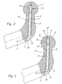
- FIG. 1 a first embodiment and from Figures 2 and 3 show two variants of a second embodiment, wherein in Figures 2 and 3, the same reference numerals as in Figure 1 with the addition of a stroke ( Figure 2) or a double stroke (FIG 3) can be used.
- truncated drawn coupling rod 1, 1 ', 1 is part of a rear arranged on a motor vehicle trailer hitch for coupling a trailer.
- the usually made of metal and in particular made of steel coupling rod 1, 1 ', 1 protrudes in its position of use to the rear over the motor vehicle and has at its rear end an upstanding coupling rod neck 2, 2', 2", to the above a spherical coupling head 3, 3 ', 3 "attached for releasably securing a trailer is.
- the coupling rod 1, 1 ', 1 with the coupling rod neck 2, 2', 2" and the coupling head 3, 3 ', 3 "integrally connected to each other.
- the coupling rod neck 2, 2 ', 2 has a cylindrical shape, its diameter being standardized and currently 29 mm with a tolerance of 2 mm downwards, with the coupling rod neck 2, 2', 2" having a smaller diameter as the coupling head 3, 3 ', 3 "and the coupling rod neck 2, 2', 2" adjacent portion 4, 4 ', 4 "of the coupling rod, so that the coupling rod neck 2, 2', 2", so to speak, the weakest component of Towing hitch is determined and the maximum load capacity of the hitch.
- the coupling rod 1, 1 ', 1 " is in the said area 4, 4', 4" bent from its in the use position backward course up to the coupling rod neck 2, 2 ', 2 "down.
- FIG. 1 In the embodiment of Figure 1 extends, starting from the coupling rod 1 opposite top 5 of the coupling head 3, a bore 6 in the axial direction 7 of the coupling rod neck 2 through the coupling head 3 and the coupling rod neck 2 into the adjoining this coupling rod portion 4, the at least in the adjoining the coupling rod neck coupling rod portion 4 has a threaded portion 8 with an internal thread 9.
- the tension bolt 10 forming the tie rod engages in the bore 6 from the coupling head upper side 5 and is screwed to its threaded portion 8.
- the clamping screw 10 has a radially projecting screw head 11, which is supported on the coupling head 3. The clamping screw 10 is tightened so that the coupling head 3, the coupling rod neck 2 and the subsequent coupling rod portion 4 are clamped together accordingly.
- the clamping screw 10 ', 10 "engages from the underside 12', 12" of the coupling rod portion 4 ', 4 "in the bore 6', 6” and is screwed to the threaded portion 8 ', 8 "”is supported in this case on the coupling rod neck 2 ', 2" adjacent coupling rod portion 4', 4 "from. Again, the clamping screw 10 ', 10 "is tightened so that a corresponding firm clamping takes place. The effect is thus the same as described above in connection with the embodiment of Figure 1.
- the radially projecting with respect to the clamping screw shank screw head 11, 11 ', 11 may also have a different shape than the illustrated countersunk head ( Figure 1) or cylindrical head ( Figures 2 and 3).
- the internal thread 9, 9 ', 9 " is, seen in Figure 1 from the coupling head 3 and in Figures 2 and 3 from the coupling rod neck 2', 2" adjacent coupling rod portion 4 ', 4 ", beyond the coupling rod neck 2, 2' 2 "arranged.
- the clamping screw 10, 10 'receiving bore 6, 6' ends in Figures 1 and 2 in the coupling rod neck 2 adjacent coupling rod portion 4 and the coupling head 3 ', so that the respective bore 6, 6' is a blind bore.
- the bore can also be formed by a through hole, as shown in the variant of Figure 3.
- the bore 6 "extends from the underside 12" of the coupling rod region 4 "to the top side 5" of the coupling head 3 ".
- the tightening screw 10 is shorter than the throughbore 8 ", so that one of the tightening screw 10 can be closed by means of a sealing plug 15 "inserted into it the internal thread 9 "of the through hole 6" be screwed.
- the bore 6 can be extended downwards, so that an opening on the underside of the coupling rod portion 4 through hole is formed.
- clamping screw 10, 10 ', 10 may also be designed as an expansion screw.
- a screwing the clamping screw from bottom to top may be particularly advantageous if the diameter of the screw head, due to a larger diameter of the clamping screw shank, not accommodated geometrically in the standard envelope region of the coupling head can be.
Landscapes
- Engineering & Computer Science (AREA)
- Transportation (AREA)
- Mechanical Engineering (AREA)
- Mutual Connection Of Rods And Tubes (AREA)
- Accessories Of Cameras (AREA)
- Reinforcement Elements For Buildings (AREA)
- Massaging Devices (AREA)
- Percussion Or Vibration Massage (AREA)
- Clamps And Clips (AREA)
Abstract
Description
- Die Erfindung betrifft eine Anhängekupplung für Kraftfahrzeuge, die eine Kupplungsstange mit endseitigem, einstückig angeformtem Kupplungsstangenhals aufweist, an den ein kugeliger Kupplungskopf zum lösbaren Befestigen eines Anhängers einstückig angesetzt ist.
- Derartige Anhängekupplungen sind in vielfältiger Art bekannt. Dabei kann es sich um Anhängekupplungen mit feststehend oder entfernbar montierter oder bewegbar, insbesondere verschwenkbar gelagerter Kupplungsstange handeln. Im letzteren Falle kann die Kupplungsstange zwischen einer hinten vor das Fahrzeug vorstehenden Gebrauchsstellung und einer nach vorne bewegten, sozusagen versteckt untergebrachten Nichtgebrauchsstellung bewegt werden. Die vorliegende Erfindung ist bei allen diesen Anhängekupplungen anwendbar.
- Der hinsichtlich der auftretenden Belastungen kritischste Bereich ist der den Kupplungskopf tragende Kupplungsstangenhals, an dem die Kupplungsstange ihren kleinsten Durchmesser aufweist. Über diesen Kupplungsstangenhals müssen alle vom mit Hilfe der Anhängekupplung an das Zugfahrzeug angehängten Anhänger ausgeübten Kräfte und Momente übertragen werden. Dabei treten beim Anhängerbetrieb auch große dynamische Kräfte auf, die in den Kupplungskopf eingeleitet werden und im Kupplungsstangenhals zu entsprechend großen Biegespannungen führen. Zusätzlich können durch die Verwendung von Spurstabilisierungskupplungen (Schlingerdämpfung für Anhänger) oder wenn im Bereich des Kupplungskopfes ein Fahrradträger oder eine Transportplattform befestigt wird, deren Schwerpunkt verhältnismäßig weit hinter dem Kupplungskopf liegt, erhebliche dynamische Drehmomente entstehen, die in den Kupplungskopf eingeleitet werden und ebenfalls große Biegespannungen und zusätzlich noch Torsionen erzeugen.
- Diese Beanspruchungen der Kupplungsstange und dabei insbesondere des Kupplungsstangenhalses nehmen vor allem aufgrund der immer größer werdenden Fahrzeuggewichte und Anhängelasten und der stärkeren Motorisierungen stetig zu.
- Um den geschilderten Belastungen stand zu halten und einen Bruch der Kupplungsstange zu vermeiden, muss die Kupplungsstange und dabei insbesondere deren Kupplungsstangenhals entsprechend stabil sein. Dabei kann den größer werdenden Anforderungen durch Verwendung von gegenüber dem ansonsten verwendeten Standardmaterial höherwertigen Materialien Rechnung getragen werden. Dies hat jedoch einen Anstieg der Materialkosten und der mechanischen Bearbeitungskosten zur Folge.
- Ausgehend hiervon liegt der Erfindung die Aufgabe zugrunde, eine Anhängekupplung der eingangs genannten Art zu schaffen, die auf kostengünstige Weise stabil ausgebildet ist.
- Diese Aufgabe wird erfindungsgemäß dadurch gelöst, dass der Kupplungsstangenhals mittels eines den Kupplungsstangenhals in seiner axialen Richtung durchziehenden Zugankers zwischen dem Kupplungskopf und dem dem Kupplungsstangenhals benachbarten Bereich der Kupplungsstange verspannt ist.
- Durch den Zuganker, zweckmäßigerweise eine Spannschraube, wird in dem einstückig durchgehenden Material der Kupplungsstange mit dem Kupplungsstangenhals und des Kupplungskopfes, und dabei insbesondere im Bereich des Kupplungsstangenhalses, eine Druckspannung erzeugt, so dass man sozusagen eine Materialverfestigung erhält. Diese im Materialgefüge vorhandene Druckspannung stellt eine Vorspannung dar, die äußeren Zugspannungen und Zugspannungsspitzen, die durch äußere dynamische Beanspruchungen (Kräfte und Drehmomente) entstehen, entgegenwirkt. Daher können bei Verwendung des gleichen Materials größere äußere Zugspannungen als seither aufgenommen werden, so dass keine höherwertigen Materialien erforderlich sind. Oder anders ausgedrückt: Das Ergebnis des gesamten Spannungsbildes der resultierenden Zugspannung (tatsächlich zu hohe Zugspannung abzüglich der absichtlich erzeugten Druckspannung) liegt damit innerhalb der zulässigen Werte.
- Ausführungsbeispiele der Erfindung werden nachstehend anhand der Zeichnung erläutert, deren Figuren jeweils den den Kupplungskopf tragenden Endbereich einer Kupplungsstange, teilweise im Schnitt, zeigen. Dabei geht aus Figur 1 ein erstes Ausführungsbeispiel und aus den Figuren 2 und 3 zwei Varianten eines zweiten Ausführungsbeispiels hervor, wobei in den Figuren 2 und 3 die gleichen Bezugsziffern wie in Figur 1 unter Hinzufügung eines Strichs (Figur 2) bzw. eines Doppelstrichs (Figur 3) verwendet werden.
- Die aus der Zeichnung hervorgehende, abgeschnitten gezeichnete Kupplungsstange 1, 1', 1" ist Bestandteil einer hinten an einem Kraftfahrzeug angeordneten Anhängerkupplung zum Ankuppeln eines Anhängers.
- Die üblicherweise aus Metall und dabei insbesondere aus Stahl bestehende Kupplungsstange 1, 1', 1" ragt in ihrer Gebrauchsstellung nach hinten hin über das Kraftfahrzeug vor und weist an ihrem rückwärtigen Ende einen hochstehenden Kupplungsstangenhals 2, 2', 2" auf, an den oben ein kugeliger Kupplungskopf 3, 3', 3" zum lösbaren Befestigen eines Anhängers angesetzt ist. Dabei sind die Kupplungsstange 1, 1', 1" mit dem Kupplungsstangenhals 2, 2', 2" und der Kupplungskopf 3, 3', 3" einstückig miteinander verbunden.
- Der Kupplungsstangenhals 2, 2', 2" weist eine zylindrische Gestalt auf. Sein Durchmesser ist genormt und beträgt nach den gegenwärtigen Bestimmungen 29 mm mit einer Toleranz von 2 mm nach unten. Dabei weist der Kupplungsstangenhals 2, 2', 2" einen kleineren Durchmesser als der Kupplungskopf 3, 3', 3" und der dem Kupplungsstangenhals 2, 2', 2" benachbarte Bereich 4, 4', 4" der Kupplungsstange auf, so dass der Kupplungsstangenhals 2, 2', 2" sozusagen der schwächste Bestandteil der Anhängekupplung ist und die maximale Belastbarkeit der Anhängekupplung bestimmt.
- Die Kupplungsstange 1, 1', 1" ist in dem genannten Bereich 4, 4', 4" aus ihrem in Gebrauchslage nach hinten gerichteten Verlauf nach oben zum Kupplungsstangenhals 2, 2', 2" hin abgebogen.
- Zur Erhöhung der Festigkeit und Stabilität ist der Kupplungsstangenhals 2, 2', 2" mittels eines Zugankers, zweckmäßigerweise in Gestalt einer Spannschraube 10, 10', 10", zwischen dem Kupplungskopf 3, 3', 3" und dem dem Kupplungsstangenhals 2, 2', 2" an der dem Kupplungskopf 3, 3', 3" entgegengesetzten Seite benachbarten Kupplungsstangenbereich 4, 4', 4" verspannt. Durch dieses Verspannen wird im Kupplungsstangenhals 2, 2', 2" eine Druckspannung aufgebaut, die den Kupplungsstangenhals 2, 2', 2" in sich verfestigt, so dass er größere Belastungen aufnehmen kann.
- Bei dem Ausführungsbeispiel nach Figur 1 erstreckt sich, ausgehend von der der Kupplungsstange 1 entgegengesetzten Oberseite 5 des Kupplungskopfes 3, eine Bohrung 6 in axialer Richtung 7 des Kupplungsstangenhalses 2 durch den Kupplungskopf 3 und den Kupplungsstangenhals 2 bis in den sich an diesen anschließenden Kupplungsstangenbereich 4, die zumindest im sich an den Kupplungsstangenhals anschließenden Kupplungsstangenbereich 4 eine Gewindepartie 8 mit einem Innengewinde 9 aufweist. Die den Zuganker bildende Spannschraube 10 greift von der Kupplungskopf-Oberseite 5 her in die Bohrung 6 ein und ist mit deren Gewindepartie 8 verschraubt. Die Spannschraube 10 weist einen radial vorstehenden Schraubenkopf 11 auf, der sich am Kupplungskopf 3 abstützt. Die Spannschraube 10 ist fest angezogen, so dass der Kupplungskopf 3, der Kupplungsstangenhals 2 und der anschließende Kupplungsstangenbereich 4 entsprechend fest zusammengespannt sind.
- Im Falle der Figuren 2 und 3 ist die Anordnung umgekehrt so getroffen, dass eine von der dem Kupplungskopf 3', 3" entgegengesetzten Unterseite des Kupplungsstangenbereichs 4', 4" ausgehende, sich in axialer Richtung 7', 7" des Kupplungsstangenhalses 2', 2" durch den diesem benachbarten Kupplungsstangenbereich 4', 4" und den Kupplungsstangenhals 2', 2" bis in den Kupplungskopf 3', 3" erstreckende Bohrung 6', 6" vorhanden ist, die zumindest im Kupplungskopf 3', 3" eine Gewindepartie 8', 8" mit einem Innengewinde 9', 9" aufweist. Die Spannschraube 10', 10" greift von der Unterseite 12', 12" des Kupplungsstangenbereichs 4', 4" in die Bohrung 6', 6" ein und ist mit deren Gewindepartie 8', 8" verschraubt. Der Schraubenkopf 11', 11" stützt sich in diesem Falle am dem Kupplungsstangenhals 2', 2" benachbarten Kupplungsstangenbereich 4', 4" ab. Wiederum wird die Spannschraube 10', 10" fest angezogen, so dass ein entsprechend festes Verspannen stattfindet. Die Wirkung ist somit die gleiche wie oben in Zusammenhang mit dem Ausführungsbeispiel nach Figur 1 beschrieben worden ist.
- Bei allen Ausführungsbeispielen ist der dem Schraubenkopf 11, 11', 11" zugewandte Endbereich 13, 13', 13" der Bohrung 6, 6', 6" zur Aufnahme des Schraubenkopfes 11, 11', 11" aufgeweitet, so dass der Schraubenkopf 11, 11', 11" mit Bezug auf die Oberseite 5 des Kupplungskopfes 3 beziehungsweise die Unterseite 12', 12" des Kupplungsstangenbereichs 4', 4" vertieft angeordnet ist.
- Der mit Bezug auf den Spannschraubenschaft radial vorstehende Schraubenkopf 11, 11', 11" kann auch eine andere Gestalt als der dargestellte Senkkopf (Figur 1) oder zylindrische Kopf (Figuren 2 und 3) aufweisen.
- Das Innengewinde 9, 9', 9" ist, in Figur 1 vom Kupplungskopf 3 und in den Figuren 2 und 3 vom dem Kupplungsstangenhals 2', 2" benachbarten Kupplungsstangenbereich 4', 4" aus gesehen, jenseits des Kupplungsstangenhalses 2, 2', 2" angeordnet.
- Die die Spannschraube 10, 10' aufnehmende Bohrung 6, 6' endet in den Figuren 1 und 2 im dem Kupplungsstangenhals 2 benachbarten Kupplungsstangenbereich 4 bzw. im Kupplungskopf 3', so dass die jeweilige Bohrung 6, 6' eine Sackbohrung ist.
- Die Bohrung kann jedoch auch von einer Durchgangsbohrung gebildet werden, wie es bei der Variante nach Figur 3 gezeigt ist. Die Bohrung 6" erstreckt sich von der Unterseite 12" des Kupplungsstangenbereichs 4" bis zur Oberseite 5" des Kupplungskopfes 3". Es versteht sich, dass die Spannschraube 10" kürzer als die durchgehende Bohrung 8" ist, so dass ein von der Spannschraube 10" freier, dem Schraubenkopf 11" entgegengesetzter Endbereich 14" der Durchgangsbohrung 6" vorhanden ist. Dieser nach außen mündende Endbereich 14" kann mittels eines in ihn eingesetzten Verschlussstopfens 15" verschlossen sein. Dabei kann der Verschlussstopfen 15" bei entsprechend langer Gewindepartie 8" in das Innengewinde 9" der Durchgangsbohrung 6" eingeschraubt sein.
- Es versteht sich, dass auch bei der Ausführungsform nach Figur 1 die Bohrung 6 nach unten hin verlängert werden kann, so dass eine an der Unterseite des Kupplungsstangenbereichs 4 ausmündende Durchgangsbohrung gebildet wird.
- Bei allen Ausführungsformen kann die Spannschraube 10, 10', 10" auch als Dehnschraube ausgebildet sein.
- Die aus den Figuren 2 und 3 hervorgehende Lösung, d.h., ein Einschrauben der Spannschraube von unten nach oben, kann insbesondere dann von Vorteil sein, wenn der Durchmesser des Schraubenkopfes, bedingt durch einen größeren Durchmesser des Spannschraubenschaftes, im genormten Hüllbereich des Kupplungskopfes geometrisch nicht untergebracht werden kann.
Claims (10)
- Anhängekupplung für Kraftfahrzeuge, die eine Kupplungsstange mit endseitigem, einstückig angeformtem Kupplungsstangenhals aufweist, an den ein kugeliger Kupplungskopf zum lösbaren Befestigen eines Anhängers einstückig angesetzt ist,
dadurch gekennzeichnet, dass der Kupplungsstangenhals (2, 2', 2") mittels eines den Kupplungsstangenhals (2, 2', 2") in seiner axialen Richtung durchziehenden Zugankers (Spannschraube 10, 10', 10") zwischen dem Kupplungskopf (3, 3', 3") und dem dem Kupplungsstangenhals (2, 2', 2") benachbarten Bereich (4, 4', 4") der Kupplungsstange (1, 1', 1") verspannt ist. - Anhängekupplung nach Anspruch 1, dadurch gekennzeichnet, dass der Zuganker von einer Spannschraube (10, 10', 10") gebildet wird.
- Anhängekupplung nach Anspruch 2, dadurch gekennzeichnet, dass eine von der der Kupplungsstange (1) entgegengesetzten Oberseite (5) des Kupplungskopfes (3) ausgehende, sich in axialer Richtung (7) des Kupplungsstangenhalses (2) durch den Kupplungskopf (3) und den Kupplungsstangenhals (2) bis in den diesem benachbarten Kupplungsstangenbereich (4) erstreckende, zumindest im benachbarten Kupplungsstangenbereich (4) mit einem Innengewinde (9) versehene Bohrung (6) vorhanden ist, in die die Spannschraube (10) eingeschraubt ist, deren Schraubenkopf (11) sich am Kupplungskopf (3) abstützt.
- Anhängekupplung nach Anspruch 2, dadurch gekennzeichnet, dass eine von der dem Kupplungskopf (3', 3") entgegengesetzten Unterseite (12', 12") der Kupplungsstange (1',1") ausgehende, sich in axialer Richtung (7', 7") des Kupplungsstangenhalses (2', 2") durch den diesem benachbarten Kupplungsstangenbereich (4', 4") und den Kupplungsstangenhals (2', 2") bis in den Kupplungskopf (3', 3") erstreckende, zumindest im Kupplungskopf (3', 3") mit einem Innengewinde (9', 9") versehene Bohrung (6', 6") vorhanden ist, in die die Spannschraube (10', 10") eingeschraubt ist, deren Schraubenkopf (11', 11") sich am dem Kupplungsstangenhals (2', 2") benachbarten Kupplungsstangenbereich (4', 4") abstützt.
- Anhängekupplung nach Anspruch 3 oder 4, dadurch gekennzeichnet, dass das Inngewinde (9 bzw. 9', 9") vom Kupplungskopf (3) bzw. vom dem Kupplungsstangenhals (2', 2") benachbarten Kupplungsstangenbereich (4', 4") aus gesehen jenseits des Kupplungsstangenhalses (2, 2', 2") angeordnet ist.
- Anhängekupplung nach einem der Ansprüche 2 bis 5, dadurch gekennzeichnet, dass die Spannschraube (10, 10', 10") eine Dehnschraube ist.
- Anhängekupplung nach einem der Ansprüche 2 bis 6, dadurch gekennzeichnet, dass der dem Schraubenkopf (11, 11', 11") zugewandte Endbereich (13, 13', 13") der Bohrung (6, 6', 6") zur Aufnahme des Schraubenkopfes (11, 11', 11") aufgeweitet ist.
- Anhängekupplung nach einem der Ansprüche 2 bis 7, dadurch gekennzeichnet, dass die Bohrung (6) eine im dem Kupplungsstangenhals (2) benachbarten Kupplungsstangenbereich (4) bzw. im Kupplungskopf endende Sackbohrung ist.
- Anhängekupplung nach einem der Ansprüche 2 bis 7, dadurch gekennzeichnet, dass die Bohrung (6") eine Durchgangsbohrung ist.
- Anhängekupplung nach Anspruch 9, dadurch gekennzeichnet, dass der dem Schraubenkopf (11") entgegengesetzte Endbereich der Durchgangsbohrung (6") mittels eines in ihn eingesetzten Verschlussstopfens (15") verschlossen ist.
Applications Claiming Priority (1)
| Application Number | Priority Date | Filing Date | Title |
|---|---|---|---|
| DE102005020163A DE102005020163A1 (de) | 2005-04-30 | 2005-04-30 | Anhängerkupplung für Kraftfahrzeuge |
Publications (2)
| Publication Number | Publication Date |
|---|---|
| EP1717066A1 true EP1717066A1 (de) | 2006-11-02 |
| EP1717066B1 EP1717066B1 (de) | 2010-04-21 |
Family
ID=36591408
Family Applications (1)
| Application Number | Title | Priority Date | Filing Date |
|---|---|---|---|
| EP06001579A Expired - Lifetime EP1717066B1 (de) | 2005-04-30 | 2006-01-26 | Anhängekupplung |
Country Status (3)
| Country | Link |
|---|---|
| EP (1) | EP1717066B1 (de) |
| AT (1) | ATE465033T1 (de) |
| DE (2) | DE102005020163A1 (de) |
Families Citing this family (2)
| Publication number | Priority date | Publication date | Assignee | Title |
|---|---|---|---|---|
| DE202010008924U1 (de) * | 2010-10-29 | 2012-02-09 | Al-Ko Kober Ag | Anhängekupplung |
| DE102018200819B4 (de) * | 2018-01-18 | 2021-02-25 | Audi Ag | Anhängevorrichtung für ein Kraftfahrzeug |
Citations (4)
| Publication number | Priority date | Publication date | Assignee | Title |
|---|---|---|---|---|
| US5280941A (en) | 1993-05-24 | 1994-01-25 | Guhlin Kjall G | Anti-theft ball assembly for ball and socket trailer hitch |
| DE29609507U1 (de) | 1996-05-29 | 1996-08-14 | Westfalia-Werke Knöbel GmbH & Co., 33378 Rheda-Wiedenbrück | Kupplungskugelträgerarm und mit diesem verbindbarer Kupplungskugel für Fahrzeuganhängerkupplungen |
| DE20120530U1 (de) | 2001-12-19 | 2002-05-23 | WESTFALIA-Automotive GmbH & Co. KG, 33378 Rheda-Wiedenbrück | Anhängervorrichtung für Kraftfahrzeuge |
| US20030034633A1 (en) | 2001-08-16 | 2003-02-20 | Belinky Jacob S. | Releasable ball hitch system |
Family Cites Families (4)
| Publication number | Priority date | Publication date | Assignee | Title |
|---|---|---|---|---|
| DD252031A1 (de) * | 1986-08-05 | 1987-12-02 | Elbe Kraftwerke Veb | Laufschaufel fuer gasturbinen |
| DE3725013A1 (de) * | 1987-07-29 | 1989-02-09 | Schloemann Siemag Ag | Spannvorrichtung fuer ringkoerper auf einer beidseitig gelagerten welle |
| DE19733313A1 (de) * | 1997-08-01 | 1999-02-18 | Oris Fahrzeugteile Riehle H | Anhängevorrichtung |
| DE29716355U1 (de) * | 1997-09-11 | 1999-01-28 | AL-KO Kober AG, 89359 Kötz | Anhängevorrichtung, insbesondere für Kraftfahrzeuge |
-
2005
- 2005-04-30 DE DE102005020163A patent/DE102005020163A1/de not_active Withdrawn
-
2006
- 2006-01-26 EP EP06001579A patent/EP1717066B1/de not_active Expired - Lifetime
- 2006-01-26 DE DE502006006750T patent/DE502006006750D1/de not_active Expired - Lifetime
- 2006-01-26 AT AT06001579T patent/ATE465033T1/de not_active IP Right Cessation
Patent Citations (4)
| Publication number | Priority date | Publication date | Assignee | Title |
|---|---|---|---|---|
| US5280941A (en) | 1993-05-24 | 1994-01-25 | Guhlin Kjall G | Anti-theft ball assembly for ball and socket trailer hitch |
| DE29609507U1 (de) | 1996-05-29 | 1996-08-14 | Westfalia-Werke Knöbel GmbH & Co., 33378 Rheda-Wiedenbrück | Kupplungskugelträgerarm und mit diesem verbindbarer Kupplungskugel für Fahrzeuganhängerkupplungen |
| US20030034633A1 (en) | 2001-08-16 | 2003-02-20 | Belinky Jacob S. | Releasable ball hitch system |
| DE20120530U1 (de) | 2001-12-19 | 2002-05-23 | WESTFALIA-Automotive GmbH & Co. KG, 33378 Rheda-Wiedenbrück | Anhängervorrichtung für Kraftfahrzeuge |
Also Published As
| Publication number | Publication date |
|---|---|
| EP1717066B1 (de) | 2010-04-21 |
| DE502006006750D1 (de) | 2010-06-02 |
| DE102005020163A1 (de) | 2006-11-02 |
| ATE465033T1 (de) | 2010-05-15 |
Similar Documents
| Publication | Publication Date | Title |
|---|---|---|
| EP3191722A2 (de) | Mutter für eine klemmvorrichtung einer vulkanisierpresse, eine klemmvorrichtung, eine vulkanisierpresse und eine tragevorrichtung für bauteile einer vulkanisierpresse | |
| DE102016102133A1 (de) | Achseinheit | |
| WO2018060228A1 (de) | Anhängekupplung mit einem stützelement | |
| DE102009030633A1 (de) | Achseinbindung für gefederte Fahrzeugachsen sowie Platte zum Einbinden einer Fahrzeugachse | |
| EP4299501B1 (de) | Verbindungsvorrichtung zur verbindung von auslegersegmenten eines auslegers eines turmdrehkrans | |
| EP2795019B1 (de) | Gegenseitige, lösbare verbindung zweier stützenabschnitte einer längenveränderlichen baustütze | |
| EP1717066B1 (de) | Anhängekupplung | |
| DE19748117C2 (de) | Kugelzapfen | |
| DE102013006240A1 (de) | Radträger für die Radaufhängung eines Fahrzeugs | |
| EP3379091A1 (de) | Befestigungsvorrichtung für ein spannband | |
| DE4429821C2 (de) | Heckgepäckträger | |
| EP1900592B1 (de) | Zugeinrichtung für Schienenfahrzeuge | |
| DE202022002881U1 (de) | Gegen Lösen gesicherter Zurrhaken für eine Spannvorrichtung und Fahrzeugsicherheitsspannvorrichtung mit einem derartigen Zurrhaken | |
| DE102008009639B4 (de) | Fahrradpedal | |
| DE10107965B4 (de) | Schleppvorrichtung für ein Fahrzeug mit einer Zugstange | |
| EP3825202B1 (de) | Zugstange, insbesondere für eine mittelpufferkupplung eines schienenfahrzeugs, und mutter zur verbindung eines zugankers einer zugstange mit einem zugrohr der zugstange | |
| DE19636186C1 (de) | Manuell längenveränderliche Zugvorrichtung für mehrachsige Anhänger | |
| DE3611245A1 (de) | Blechverbindung mit einem verbindungselement mit schaft und kopf | |
| DE20305197U1 (de) | Spanneinrichtung zum Verzurren von Containern | |
| DE2815503C2 (de) | Zuggabellagerung für Anhänger von Kraftfahrzeugen | |
| DE69705290T2 (de) | Getriebegehäuse für einen Schlepper | |
| AT408409B (de) | Schubkastenausziehvorrichtung | |
| EP3611083B2 (de) | Kupplungsplatte für eine sattelkupplung | |
| DE3334250C2 (de) | ||
| EP1279843B1 (de) | Metall-Trägerteil mit einer angeschweissten Lagerbuchse |
Legal Events
| Date | Code | Title | Description |
|---|---|---|---|
| PUAI | Public reference made under article 153(3) epc to a published international application that has entered the european phase |
Free format text: ORIGINAL CODE: 0009012 |
|
| 17P | Request for examination filed |
Effective date: 20060921 |
|
| AK | Designated contracting states |
Kind code of ref document: A1 Designated state(s): AT BE BG CH CY CZ DE DK EE ES FI FR GB GR HU IE IS IT LI LT LU LV MC NL PL PT RO SE SI SK TR |
|
| AX | Request for extension of the european patent |
Extension state: AL BA HR MK YU |
|
| AKX | Designation fees paid |
Designated state(s): AT BE BG CH CY CZ DE DK EE ES FI FR GB GR HU IE IS IT LI LT LU LV MC NL PL PT RO SE SI SK TR |
|
| 17Q | First examination report despatched |
Effective date: 20070806 |
|
| GRAP | Despatch of communication of intention to grant a patent |
Free format text: ORIGINAL CODE: EPIDOSNIGR1 |
|
| GRAS | Grant fee paid |
Free format text: ORIGINAL CODE: EPIDOSNIGR3 |
|
| GRAA | (expected) grant |
Free format text: ORIGINAL CODE: 0009210 |
|
| AK | Designated contracting states |
Kind code of ref document: B1 Designated state(s): AT BE BG CH CY CZ DE DK EE ES FI FR GB GR HU IE IS IT LI LT LU LV MC NL PL PT RO SE SI SK TR |
|
| REG | Reference to a national code |
Ref country code: GB Ref legal event code: FG4D Free format text: NOT ENGLISH |
|
| REG | Reference to a national code |
Ref country code: CH Ref legal event code: EP |
|
| REG | Reference to a national code |
Ref country code: IE Ref legal event code: FG4D Free format text: LANGUAGE OF EP DOCUMENT: GERMAN |
|
| REF | Corresponds to: |
Ref document number: 502006006750 Country of ref document: DE Date of ref document: 20100602 Kind code of ref document: P |
|
| REG | Reference to a national code |
Ref country code: NL Ref legal event code: VDEP Effective date: 20100421 |
|
| LTIE | Lt: invalidation of european patent or patent extension |
Effective date: 20100421 |
|
| PG25 | Lapsed in a contracting state [announced via postgrant information from national office to epo] |
Ref country code: LT Free format text: LAPSE BECAUSE OF FAILURE TO SUBMIT A TRANSLATION OF THE DESCRIPTION OR TO PAY THE FEE WITHIN THE PRESCRIBED TIME-LIMIT Effective date: 20100421 Ref country code: SE Free format text: LAPSE BECAUSE OF FAILURE TO SUBMIT A TRANSLATION OF THE DESCRIPTION OR TO PAY THE FEE WITHIN THE PRESCRIBED TIME-LIMIT Effective date: 20100421 Ref country code: NL Free format text: LAPSE BECAUSE OF FAILURE TO SUBMIT A TRANSLATION OF THE DESCRIPTION OR TO PAY THE FEE WITHIN THE PRESCRIBED TIME-LIMIT Effective date: 20100421 Ref country code: ES Free format text: LAPSE BECAUSE OF FAILURE TO SUBMIT A TRANSLATION OF THE DESCRIPTION OR TO PAY THE FEE WITHIN THE PRESCRIBED TIME-LIMIT Effective date: 20100801 |
|
| REG | Reference to a national code |
Ref country code: IE Ref legal event code: FD4D |
|
| PG25 | Lapsed in a contracting state [announced via postgrant information from national office to epo] |
Ref country code: FI Free format text: LAPSE BECAUSE OF FAILURE TO SUBMIT A TRANSLATION OF THE DESCRIPTION OR TO PAY THE FEE WITHIN THE PRESCRIBED TIME-LIMIT Effective date: 20100421 Ref country code: IS Free format text: LAPSE BECAUSE OF FAILURE TO SUBMIT A TRANSLATION OF THE DESCRIPTION OR TO PAY THE FEE WITHIN THE PRESCRIBED TIME-LIMIT Effective date: 20100821 Ref country code: LV Free format text: LAPSE BECAUSE OF FAILURE TO SUBMIT A TRANSLATION OF THE DESCRIPTION OR TO PAY THE FEE WITHIN THE PRESCRIBED TIME-LIMIT Effective date: 20100421 Ref country code: SI Free format text: LAPSE BECAUSE OF FAILURE TO SUBMIT A TRANSLATION OF THE DESCRIPTION OR TO PAY THE FEE WITHIN THE PRESCRIBED TIME-LIMIT Effective date: 20100421 |
|
| PG25 | Lapsed in a contracting state [announced via postgrant information from national office to epo] |
Ref country code: PL Free format text: LAPSE BECAUSE OF FAILURE TO SUBMIT A TRANSLATION OF THE DESCRIPTION OR TO PAY THE FEE WITHIN THE PRESCRIBED TIME-LIMIT Effective date: 20100421 Ref country code: CY Free format text: LAPSE BECAUSE OF FAILURE TO SUBMIT A TRANSLATION OF THE DESCRIPTION OR TO PAY THE FEE WITHIN THE PRESCRIBED TIME-LIMIT Effective date: 20100505 Ref country code: GR Free format text: LAPSE BECAUSE OF FAILURE TO SUBMIT A TRANSLATION OF THE DESCRIPTION OR TO PAY THE FEE WITHIN THE PRESCRIBED TIME-LIMIT Effective date: 20100722 |
|
| PG25 | Lapsed in a contracting state [announced via postgrant information from national office to epo] |
Ref country code: IE Free format text: LAPSE BECAUSE OF FAILURE TO SUBMIT A TRANSLATION OF THE DESCRIPTION OR TO PAY THE FEE WITHIN THE PRESCRIBED TIME-LIMIT Effective date: 20100421 Ref country code: PT Free format text: LAPSE BECAUSE OF FAILURE TO SUBMIT A TRANSLATION OF THE DESCRIPTION OR TO PAY THE FEE WITHIN THE PRESCRIBED TIME-LIMIT Effective date: 20100823 Ref country code: DK Free format text: LAPSE BECAUSE OF FAILURE TO SUBMIT A TRANSLATION OF THE DESCRIPTION OR TO PAY THE FEE WITHIN THE PRESCRIBED TIME-LIMIT Effective date: 20100421 Ref country code: EE Free format text: LAPSE BECAUSE OF FAILURE TO SUBMIT A TRANSLATION OF THE DESCRIPTION OR TO PAY THE FEE WITHIN THE PRESCRIBED TIME-LIMIT Effective date: 20100421 |
|
| PLBE | No opposition filed within time limit |
Free format text: ORIGINAL CODE: 0009261 |
|
| STAA | Information on the status of an ep patent application or granted ep patent |
Free format text: STATUS: NO OPPOSITION FILED WITHIN TIME LIMIT |
|
| PG25 | Lapsed in a contracting state [announced via postgrant information from national office to epo] |
Ref country code: SK Free format text: LAPSE BECAUSE OF FAILURE TO SUBMIT A TRANSLATION OF THE DESCRIPTION OR TO PAY THE FEE WITHIN THE PRESCRIBED TIME-LIMIT Effective date: 20100421 Ref country code: RO Free format text: LAPSE BECAUSE OF FAILURE TO SUBMIT A TRANSLATION OF THE DESCRIPTION OR TO PAY THE FEE WITHIN THE PRESCRIBED TIME-LIMIT Effective date: 20100421 Ref country code: CZ Free format text: LAPSE BECAUSE OF FAILURE TO SUBMIT A TRANSLATION OF THE DESCRIPTION OR TO PAY THE FEE WITHIN THE PRESCRIBED TIME-LIMIT Effective date: 20100421 |
|
| 26N | No opposition filed |
Effective date: 20110124 |
|
| PG25 | Lapsed in a contracting state [announced via postgrant information from national office to epo] |
Ref country code: IT Free format text: LAPSE BECAUSE OF FAILURE TO SUBMIT A TRANSLATION OF THE DESCRIPTION OR TO PAY THE FEE WITHIN THE PRESCRIBED TIME-LIMIT Effective date: 20100421 |
|
| BERE | Be: lapsed |
Owner name: WESTFALIA - AUTOMOTIVE G.M.B.H. Effective date: 20110131 |
|
| PG25 | Lapsed in a contracting state [announced via postgrant information from national office to epo] |
Ref country code: MC Free format text: LAPSE BECAUSE OF NON-PAYMENT OF DUE FEES Effective date: 20110131 |
|
| REG | Reference to a national code |
Ref country code: CH Ref legal event code: PL |
|
| GBPC | Gb: european patent ceased through non-payment of renewal fee |
Effective date: 20110126 |
|
| PG25 | Lapsed in a contracting state [announced via postgrant information from national office to epo] |
Ref country code: CH Free format text: LAPSE BECAUSE OF NON-PAYMENT OF DUE FEES Effective date: 20110131 Ref country code: LI Free format text: LAPSE BECAUSE OF NON-PAYMENT OF DUE FEES Effective date: 20110131 |
|
| PG25 | Lapsed in a contracting state [announced via postgrant information from national office to epo] |
Ref country code: BE Free format text: LAPSE BECAUSE OF NON-PAYMENT OF DUE FEES Effective date: 20110131 Ref country code: GB Free format text: LAPSE BECAUSE OF NON-PAYMENT OF DUE FEES Effective date: 20110126 |
|
| REG | Reference to a national code |
Ref country code: AT Ref legal event code: MM01 Ref document number: 465033 Country of ref document: AT Kind code of ref document: T Effective date: 20110126 |
|
| PG25 | Lapsed in a contracting state [announced via postgrant information from national office to epo] |
Ref country code: AT Free format text: LAPSE BECAUSE OF NON-PAYMENT OF DUE FEES Effective date: 20110126 |
|
| PG25 | Lapsed in a contracting state [announced via postgrant information from national office to epo] |
Ref country code: LU Free format text: LAPSE BECAUSE OF NON-PAYMENT OF DUE FEES Effective date: 20110126 |
|
| PG25 | Lapsed in a contracting state [announced via postgrant information from national office to epo] |
Ref country code: BG Free format text: LAPSE BECAUSE OF FAILURE TO SUBMIT A TRANSLATION OF THE DESCRIPTION OR TO PAY THE FEE WITHIN THE PRESCRIBED TIME-LIMIT Effective date: 20100721 Ref country code: TR Free format text: LAPSE BECAUSE OF FAILURE TO SUBMIT A TRANSLATION OF THE DESCRIPTION OR TO PAY THE FEE WITHIN THE PRESCRIBED TIME-LIMIT Effective date: 20100421 |
|
| PG25 | Lapsed in a contracting state [announced via postgrant information from national office to epo] |
Ref country code: HU Free format text: LAPSE BECAUSE OF FAILURE TO SUBMIT A TRANSLATION OF THE DESCRIPTION OR TO PAY THE FEE WITHIN THE PRESCRIBED TIME-LIMIT Effective date: 20100421 |
|
| PGFP | Annual fee paid to national office [announced via postgrant information from national office to epo] |
Ref country code: DE Payment date: 20131122 Year of fee payment: 9 |
|
| PGFP | Annual fee paid to national office [announced via postgrant information from national office to epo] |
Ref country code: FR Payment date: 20140124 Year of fee payment: 9 |
|
| REG | Reference to a national code |
Ref country code: DE Ref legal event code: R082 Ref document number: 502006006750 Country of ref document: DE Representative=s name: BREGENZER, MICHAEL, DIPL.-ING., DE Ref country code: DE Ref legal event code: R082 Ref document number: 502006006750 Country of ref document: DE Representative=s name: PATENTANWAELTE BREGENZER UND REULE PARTNERSCHA, DE |
|
| REG | Reference to a national code |
Ref country code: DE Ref legal event code: R082 Ref document number: 502006006750 Country of ref document: DE Representative=s name: PATENTANWAELTE BREGENZER UND REULE PARTNERSCHA, DE |
|
| REG | Reference to a national code |
Ref country code: DE Ref legal event code: R119 Ref document number: 502006006750 Country of ref document: DE |
|
| PG25 | Lapsed in a contracting state [announced via postgrant information from national office to epo] |
Ref country code: DE Free format text: LAPSE BECAUSE OF NON-PAYMENT OF DUE FEES Effective date: 20150801 |
|
| REG | Reference to a national code |
Ref country code: FR Ref legal event code: ST Effective date: 20150930 |
|
| PG25 | Lapsed in a contracting state [announced via postgrant information from national office to epo] |
Ref country code: FR Free format text: LAPSE BECAUSE OF NON-PAYMENT OF DUE FEES Effective date: 20150202 |