EP1716885A2 - Verbindungsanordnungen, Fluidsysteme und Methoden zum Erstellen einer Verbindung - Google Patents
Verbindungsanordnungen, Fluidsysteme und Methoden zum Erstellen einer Verbindung Download PDFInfo
- Publication number
- EP1716885A2 EP1716885A2 EP06076411A EP06076411A EP1716885A2 EP 1716885 A2 EP1716885 A2 EP 1716885A2 EP 06076411 A EP06076411 A EP 06076411A EP 06076411 A EP06076411 A EP 06076411A EP 1716885 A2 EP1716885 A2 EP 1716885A2
- Authority
- EP
- European Patent Office
- Prior art keywords
- fitting
- aperture
- cap
- stem
- male
- Prior art date
- Legal status (The legal status is an assumption and is not a legal conclusion. Google has not performed a legal analysis and makes no representation as to the accuracy of the status listed.)
- Withdrawn
Links
Images


Classifications
-
- A—HUMAN NECESSITIES
- A61—MEDICAL OR VETERINARY SCIENCE; HYGIENE
- A61M—DEVICES FOR INTRODUCING MEDIA INTO, OR ONTO, THE BODY; DEVICES FOR TRANSDUCING BODY MEDIA OR FOR TAKING MEDIA FROM THE BODY; DEVICES FOR PRODUCING OR ENDING SLEEP OR STUPOR
- A61M39/00—Tubes, tube connectors, tube couplings, valves, access sites or the like, specially adapted for medical use
- A61M39/10—Tube connectors; Tube couplings
- A61M39/1011—Locking means for securing connection; Additional tamper safeties
-
- A—HUMAN NECESSITIES
- A61—MEDICAL OR VETERINARY SCIENCE; HYGIENE
- A61M—DEVICES FOR INTRODUCING MEDIA INTO, OR ONTO, THE BODY; DEVICES FOR TRANSDUCING BODY MEDIA OR FOR TAKING MEDIA FROM THE BODY; DEVICES FOR PRODUCING OR ENDING SLEEP OR STUPOR
- A61M39/00—Tubes, tube connectors, tube couplings, valves, access sites or the like, specially adapted for medical use
- A61M39/10—Tube connectors; Tube couplings
- A61M39/14—Tube connectors; Tube couplings for connecting tubes having sealed ends
-
- A—HUMAN NECESSITIES
- A61—MEDICAL OR VETERINARY SCIENCE; HYGIENE
- A61M—DEVICES FOR INTRODUCING MEDIA INTO, OR ONTO, THE BODY; DEVICES FOR TRANSDUCING BODY MEDIA OR FOR TAKING MEDIA FROM THE BODY; DEVICES FOR PRODUCING OR ENDING SLEEP OR STUPOR
- A61M39/00—Tubes, tube connectors, tube couplings, valves, access sites or the like, specially adapted for medical use
- A61M39/10—Tube connectors; Tube couplings
- A61M39/16—Tube connectors; Tube couplings having provision for disinfection or sterilisation
- A61M39/18—Methods or apparatus for making the connection under sterile conditions, i.e. sterile docking
-
- F—MECHANICAL ENGINEERING; LIGHTING; HEATING; WEAPONS; BLASTING
- F16—ENGINEERING ELEMENTS AND UNITS; GENERAL MEASURES FOR PRODUCING AND MAINTAINING EFFECTIVE FUNCTIONING OF MACHINES OR INSTALLATIONS; THERMAL INSULATION IN GENERAL
- F16L—PIPES; JOINTS OR FITTINGS FOR PIPES; SUPPORTS FOR PIPES, CABLES OR PROTECTIVE TUBING; MEANS FOR THERMAL INSULATION IN GENERAL
- F16L37/00—Couplings of the quick-acting type
- F16L37/08—Couplings of the quick-acting type in which the connection between abutting or axially overlapping ends is maintained by locking members
- F16L37/084—Couplings of the quick-acting type in which the connection between abutting or axially overlapping ends is maintained by locking members combined with automatic locking
- F16L37/098—Couplings of the quick-acting type in which the connection between abutting or axially overlapping ends is maintained by locking members combined with automatic locking by means of flexible hooks
- F16L37/0985—Couplings of the quick-acting type in which the connection between abutting or axially overlapping ends is maintained by locking members combined with automatic locking by means of flexible hooks the flexible hook extending radially inwardly from an outer part and engaging a bead, recess or the like on an inner part
-
- F—MECHANICAL ENGINEERING; LIGHTING; HEATING; WEAPONS; BLASTING
- F16—ENGINEERING ELEMENTS AND UNITS; GENERAL MEASURES FOR PRODUCING AND MAINTAINING EFFECTIVE FUNCTIONING OF MACHINES OR INSTALLATIONS; THERMAL INSULATION IN GENERAL
- F16L—PIPES; JOINTS OR FITTINGS FOR PIPES; SUPPORTS FOR PIPES, CABLES OR PROTECTIVE TUBING; MEANS FOR THERMAL INSULATION IN GENERAL
- F16L47/00—Connecting arrangements or other fittings specially adapted to be made of plastics or to be used with pipes made of plastics
- F16L47/14—Flanged joints
-
- A—HUMAN NECESSITIES
- A61—MEDICAL OR VETERINARY SCIENCE; HYGIENE
- A61M—DEVICES FOR INTRODUCING MEDIA INTO, OR ONTO, THE BODY; DEVICES FOR TRANSDUCING BODY MEDIA OR FOR TAKING MEDIA FROM THE BODY; DEVICES FOR PRODUCING OR ENDING SLEEP OR STUPOR
- A61M39/00—Tubes, tube connectors, tube couplings, valves, access sites or the like, specially adapted for medical use
- A61M39/02—Access sites
-
- F—MECHANICAL ENGINEERING; LIGHTING; HEATING; WEAPONS; BLASTING
- F16—ENGINEERING ELEMENTS AND UNITS; GENERAL MEASURES FOR PRODUCING AND MAINTAINING EFFECTIVE FUNCTIONING OF MACHINES OR INSTALLATIONS; THERMAL INSULATION IN GENERAL
- F16L—PIPES; JOINTS OR FITTINGS FOR PIPES; SUPPORTS FOR PIPES, CABLES OR PROTECTIVE TUBING; MEANS FOR THERMAL INSULATION IN GENERAL
- F16L2201/00—Special arrangements for pipe couplings
- F16L2201/40—Special arrangements for pipe couplings for special environments
- F16L2201/44—Special arrangements for pipe couplings for special environments sterile
-
- Y—GENERAL TAGGING OF NEW TECHNOLOGICAL DEVELOPMENTS; GENERAL TAGGING OF CROSS-SECTIONAL TECHNOLOGIES SPANNING OVER SEVERAL SECTIONS OF THE IPC; TECHNICAL SUBJECTS COVERED BY FORMER USPC CROSS-REFERENCE ART COLLECTIONS [XRACs] AND DIGESTS
- Y10—TECHNICAL SUBJECTS COVERED BY FORMER USPC
- Y10S—TECHNICAL SUBJECTS COVERED BY FORMER USPC CROSS-REFERENCE ART COLLECTIONS [XRACs] AND DIGESTS
- Y10S285/00—Pipe joints or couplings
- Y10S285/915—Mastic
-
- Y—GENERAL TAGGING OF NEW TECHNOLOGICAL DEVELOPMENTS; GENERAL TAGGING OF CROSS-SECTIONAL TECHNOLOGIES SPANNING OVER SEVERAL SECTIONS OF THE IPC; TECHNICAL SUBJECTS COVERED BY FORMER USPC CROSS-REFERENCE ART COLLECTIONS [XRACs] AND DIGESTS
- Y10—TECHNICAL SUBJECTS COVERED BY FORMER USPC
- Y10S—TECHNICAL SUBJECTS COVERED BY FORMER USPC CROSS-REFERENCE ART COLLECTIONS [XRACs] AND DIGESTS
- Y10S604/00—Surgery
- Y10S604/905—Aseptic connectors or couplings, e.g. frangible, piercable
-
- Y—GENERAL TAGGING OF NEW TECHNOLOGICAL DEVELOPMENTS; GENERAL TAGGING OF CROSS-SECTIONAL TECHNOLOGIES SPANNING OVER SEVERAL SECTIONS OF THE IPC; TECHNICAL SUBJECTS COVERED BY FORMER USPC CROSS-REFERENCE ART COLLECTIONS [XRACs] AND DIGESTS
- Y10—TECHNICAL SUBJECTS COVERED BY FORMER USPC
- Y10T—TECHNICAL SUBJECTS COVERED BY FORMER US CLASSIFICATION
- Y10T137/00—Fluid handling
- Y10T137/8593—Systems
- Y10T137/87917—Flow path with serial valves and/or closures
- Y10T137/87925—Separable flow path section, valve or closure in each
- Y10T137/87933—Common joint and valve seat faces, or sections joined by closing members
-
- Y—GENERAL TAGGING OF NEW TECHNOLOGICAL DEVELOPMENTS; GENERAL TAGGING OF CROSS-SECTIONAL TECHNOLOGIES SPANNING OVER SEVERAL SECTIONS OF THE IPC; TECHNICAL SUBJECTS COVERED BY FORMER USPC CROSS-REFERENCE ART COLLECTIONS [XRACs] AND DIGESTS
- Y10—TECHNICAL SUBJECTS COVERED BY FORMER USPC
- Y10T—TECHNICAL SUBJECTS COVERED BY FORMER US CLASSIFICATION
- Y10T29/00—Metal working
- Y10T29/49—Method of mechanical manufacture
- Y10T29/49826—Assembling or joining
- Y10T29/49863—Assembling or joining with prestressing of part
- Y10T29/4987—Elastic joining of parts
- Y10T29/49872—Confining elastic part in socket
Definitions
- the present invention relates to connector assemblies, fluid systems or devices including a connector assembly, and methods for making a connection. More particularly, the invention relates to connector assemblies and fluid systems or devices, which maintain the sterility of a fluid which passes through them, and methods for making a sterile connection.
- Connector assemblies have been developed to handle fluids, e.g., biological fluids, while preserving their condition. More particularly, connectors have been developed to preserve the condition of a fluid, or maintain a fluid free of contaminants. Freedom from contaminants refers to a relative amount of contaminants and is variously defined according to a specific industry, fluid and/or intended use. For example, a biological fluid is considered free of contaminants if it is substantially free of viable microorganisms and is typically referred to as "sterile". Connector assemblies for use with biological fluids, for example, have been fashioned to preserve sterility of the fluid.
- connector assemblies which isolate a fluid from the ambient environment of the connector, and from contaminants entrained in the ambient environment. Such connectors typically define a fluid conduit, the interior of which is isolated from the ambient environment.
- Some conventional connector assemblies include mating male and female connectors having opposing surfaces and a removable protective cover on each opposing surface to be contacted. These covers must be removed prior to actually coupling the connectors.
- a problem associated with these conventional connector assemblies in which protective covers must be removed prior to coupling is that removing the covers may not sufficiently protect the fluid flowing through these assemblies.
- a technician To unfasten and remove a cover, a technician must manually manipulate the removable cover in intimate proximity to the protected region under the cover, risking incidental contact and the transmission of contaminants to the protected region.
- the protected regions are exposed to the contaminant-laden ambient environment.
- dust, micro-organisms, and other airborne contaminants may contact the protected regions, even if the connectors are quickly mated.
- Another type of conventional connector assembly comprises mating male and female fittings, each fitting having a protective cover attached to a connecting end of the fitting, and a piercing member inside the male fitting to pierce the protective covers and join the interiors of the mating fittings.
- One problem with these fittings is that the piercing member may prematurely pierce the cover before the fittings are coupled together. As a result, contaminants may enter the connector and it must either be resterilized or discarded.
- the piercing member may sever a portion of one or both of the covers between the connecting ends of the male and female fittings when the fittings are coupled together.
- the severed portion of the membrane may enter a fluid flow path defined by the interior region of the fittings and contaminate the system or interfere with the flow of fluid through the connector.
- a connector assembly comprises a first fitting, a second fitting, a socket, a resilient sealing member, and a stem.
- the first fitting includes an aperture and the second fitting, which is capable of being coupled to the first fitting, also includes an aperture.
- the socket which includes a side wall, is cooperatively arranged with the first fitting or the second fitting.
- the resilient sealing member is disposed in the socket.
- the resilient sealing member includes a first portion which contacts the side wall of the socket and a second portion which is spaced from the side wall of the socket.
- the stem which includes a head, is disposed in the first fitting. The stem is axially movable through the socket and the resilient sealing member into the aperture of the second fitting.
- a connector assembly comprises a first fitting, a second fitting, a socket, a resilient sealing member, and a stem.
- the first fitting includes an aperture and the second fitting, which is capable of being coupled to the first fitting, also includes an aperture.
- the socket is cooperatively arranged with the first fitting or the second fitting.
- the resilient sealing member which is disposed in the socket, includes a first portion and a second portion having a thinner wall than the first portion.
- the stem which includes a head, is disposed in the first fitting. The stem is axially movable through the socket and the resilient sealing member into the aperture of the second fitting.
- a connector assembly comprises a first fitting, a second fitting, a stem, a socket, a resilient sealing member, and a sealing layer.
- the first fitting has an aperture and the second fitting, which is capable of being coupled to the first fitting, also has an aperture.
- the stem is disposed in the first fitting.
- the socket which includes an open end, is cooperatively arranged with the first fitting or the second fitting.
- the resilient sealing member is disposed in the socket, and the sealing layer is joined to the open end of the socket.
- a connector assembly comprises a first fitting, a second fitting, a socket, a resilient sealing member, a sealing layer, and a stem.
- the first fitting has an aperture and the second fitting, which is capable of being coupled to the first fitting, also has an aperture.
- the socket which includes a continuous cylindrical wall, is cooperatively arranged with the first fitting or the second fitting.
- the resilient sealing member is disposed in the socket, and the sealing layer covers the resilient sealing member.
- the stem which includes a head, is disposed in the first fitting. The stem is axially movable through the socket and the resilient sealing member into the aperture of the second fitting.
- a connector assembly comprises a first fitting, a second fitting, a first resilient sealing member, a second resilient sealing member, a sealing layer, and a stem.
- the first fitting has an aperture and the second fitting, which is coupleable to the first fitting, also has an aperture.
- the first resilient sealing member is coupled to the first fitting at the aperture of the first fitting, and the second resilient sealing member is coupled to the second fitting at the aperture of the second fitting.
- the sealing layer is disposed between the first and second resilient sealing members, and the stem is disposed in the first fitting.
- a connector assembly comprises a first fitting, a second fitting, a stem, and a deformable locking device.
- the first fitting has an aperture
- the second fitting which is capable of being coupled to the first fitting, also has an aperture.
- the stem which includes a head, is disposed in the first fitting.
- the stem is axially movable into the aperture of the second fitting.
- the deformable locking device includes an axially extending member arranged between the first fitting and the stem to prevent the head from moving through the aperture of the first fitting.
- a connector assembly comprises first and second fittings, a first cap and a stem.
- the first fitting has an aperture and a proximal end.
- the second fitting is coupleable to the first fitting and has an aperture and a proximal end.
- the first cap is operatively associated with the proximal end of one of the first and second fittings, and protects the proximal end of the one of the first and second fittings.
- the stem includes a head, and is disposed in the first fitting and axially movable through the aperture of the first fitting into the aperture of the second fitting.
- a fluid system or device comprises any of the previous connector assemblies and a fluid container or conduit.
- the container or conduit is coupled to either one of the first and second fittings of the connector assembly.
- a method for making a connection comprises mating a first fitting having an aperture and a second fitting having an aperture without fluid within the first and second fittings, establishing a fluid flowpath through the first and second fittings by advancing a stem having a head through the aperture of the first fitting into the aperture of the second fitting, and establishing fluid flow through the first and second fittings by opening a fluid blocking mechanism.
- a method for making a connection comprises removing a cap operatively associated with a proximal end of one of a first fitting and a second fitting, each of which has an aperture, mating the first fitting and the second fitting, removing stripout layers covering respectively the apertures of the first and second fittings, and establishing a fluid flowpath through the first and second fittings by advancing a stem having a head through the aperture of the first fitting into the aperture of the second fitting.
- a connector assembly includes mating connectors which can be coupled to connect different fluid conduit sections defining a fluid flow path, e.g., a liquid flow path.
- the connector assembly isolates the fluid flow path from the ambient environment and from contaminants present in the ambient environment and is preferably sterile. Consequently, a connector assembly according to the present invention is suitable for use in an open system, a closed system, or a closed sterile system.
- the connector assembly comprises two connectors, preferably a female connector 100 and a male connector 200.
- Each connector may be attached to or formed as part of any suitable fluid container or conduit, for example, a section of tubing, an inlet or outlet of a housing, such as a filter housing or drip chamber housing, or a flexible bag such as a blood bag.
- Each connector may comprise any structure suitable for fluid communication, preferably liquid communication, e.g. a housing of any form capable of containing fluid.
- the exemplary female connector 100 generally comprises a fitting 120, preferably of unitary construction.
- An exemplary male connector 200 generally comprises a stem 210 and a fitting 220.
- the fittings 120,220 of the female and male connectors 100,200 are preferably formed from a polymeric material.
- the fittings 120,220 may be molded from a polymeric material such as polycarbonate or polypropylene.
- each connector has a proximal end, nearest the opposing connector, and a distal end furthest from the opposing connector.
- exemplary connectors 100, 200 in Figure 1 comprise generally elongated bodies, the term axial denotes disposition along their axes.
- the female and male connectors 100, 200 may also comprise an interlocking mechanism adapted to interlock the female connector 100 in predetermined relation with the male connector 200.
- the interlocking mechanism may have any suitable configuration, such as interlocking sleeves or threaded connections.
- the portion of the interlocking mechanism on the female fitting 120 may include a bracket 140.
- the bracket 140 may be variously configured.
- the bracket 140 may comprise a socket 145 or cup having any suitable plan form, e.g. rectangular or circular.
- the bracket 140 comprises a generally C-shaped member.
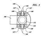
- the representative bracket 140 may include a flange 142 and a generally cylindrical sidewall 144 defining a socket 145.
- the flange 142 may assume a radially extending annular plan form, for example, as best seen in Figure 5.
- the sidewall 144 extends from and is concentric with the flange 142 and includes an annular proximal end surface 143 facing the male connector 200.
- One or more forks 146 may extend from the flange 142.
- the forks 146 may be formed integrally with the flange 142.
- the forks 146 When the female connector 100 is coupled to the male connector 200, the forks 146 preferably register in slots 240 formed in an upper flange 242 of the male connector 200. While in the illustrated embodiment, the forks 146 extend from the female connector 100 and the slots 240 are in the male connector 200, the forks and slots may instead be associated with the male and female connectors, respectively.
- the forks 146 are best illustrated in Figure 5.
- the slots 240 are best illustrated in Figure 4.
- Each fork 146 preferably comprises first and second prongs 147 which are preferably flexible to allow the prongs 147 to enter and lock in the slots 240.
- Catches 148 can be formed on the prongs 147 of the forks 146 which pass through the slots 240 and abut a distal surface of the upper flange 242. In this manner, the forks 146 extend through the slots 240 and engage the upper flange 242 of the male connector 200 to interlock the connectors 100, 200.
- the female connector 100 is preferably adapted to contain fluid and conduct fluid communication and preferably defines an isolated portion of the fluid flow path, e.g., containing or conducting isolated fluid communication.
- the female fitting 120 may define an internal chamber or aperture 132 which may have any suitable configuration and preferably has an open proximal end.
- the distal end 126 of the female fitting 120 may be connected to any suitable fluid container or conduit as best shown on Figures 11-14.
- the distal end 126 of the female fitting 120 may be bonded to a section of tubing 10 or to the top, the bottom or the wall of a container using any suitable bonding technique.
- the female fitting 120 may be molded integrally with the tubing 10 or the container.
- the fluid conduit or container may be connected in fluid communication with the internal chamber 132 of the female fitting 120.
- the internal chamber 132 may comprise a bore 134 relieved at its proximal end into a counterbore 136 having a larger inner diameter than the bore 134.
- the cylindrical sidewall 144 surrounds the proximal end of the chamber 132 and defines the counterbore 136.
- the female connector 100 preferably further comprises a sealing layer sealing the open proximal end of the aperture 132 in the female fitting 120.
- the sealing layer preferably comprises a removable sealing layer, such as a female stripout layer 300 removably attached to the proximal end of the female fitting 120.
- the female stripout layer 300 is attached to the open proximal end of the sidewall 144.
- the female stripout layer 300 may be bonded to the proximal end surface 143 of the female fitting 120 through any suitable technique, for example, ultrasonic welding.
- the stripout sealing layer 300 preferably seals the chamber 132 of the female connector 100 from the ambient atmosphere.
- the female stripout sealing layer 300 preferably includes a pull tab that extends beyond the periphery of the connectors 100, 200 to allow removal when the connectors 100, 200 are joined.
- the male connector 100 also preferably comprises a sealing layer which seals the open proximal end of an aperture 232 in the male fitting 220.
- the sealing layer preferably comprises a removable sealing layer such as a male stripout layer 310 removably attached to the proximal end of the male fitting 220.
- the male stripout layer 310 is attached to the proximal end surface 243 at the open end of a generally cylindrical sidewall 244 at the proximal end of the male fitting 220.
- the inner and outer diameters of the male sidewall 244 may be approximately equal to those of the female sidewall 144.
- the male stripout sealing layer 310 may be bonded to the proximal end surface 243 of the male connector through any suitable technique, for example, ultrasonic welding.
- the male stripout sealing layer 310 preferably seals the interior of the male connector 200 from the ambient environment.
- the male stripout sealing layer 310 preferably includes a pull tab that extends beyond the periphery of the connectors 100, 200 to allow removal when the connectors 100, 200 are joined.
- the female and male stripout sealing layers 300, 310 preferably abut one another in face-to-face contact.
- the diameters and locations of the female and male sidewalls 144, 244 and the lengths of the forks 146 and the sidewalls 144, 244 may be arranged to provide face-to-face contact of the stripout layers 300, 310 between the end surfaces 143, 243 of the sidewalls 144, 244 when the connectors 100, 200 are coupled.
- the dimensions may be arranged to provide not only contact but also a slight compression of the stripout layers 300, 310 between the end surfaces 143, 243.
- the compression is preferably not so large as to interfere with the removal of the stripout layers 300, 310 from between the sidewalls 144, 244.
- the compression may be somewhat larger.
- the dimensions and locations of the forks 146 and the sidewalls 144, 244 may be arranged to provide a slight space between the female and male stripout layers 300, 310.
- the combined length of the sidewalls 144, 244 may be less than the distance between the flanges 142, 242.
- the space is sufficiently small to prevent significant axial movement of the connectors 100, 200 when they are connected to one another.
- the stripout layers 300, 310 may comprise impermeable materials, such as glassine paper, metal foils, or impermeable polymeric films, or permeable materials, including papers such as TyvekTM paper or porous polymeric films, which preclude the passage of bacterial contaminants.
- a preferred impermeable material is an aluminum foil which is removably sealed to the fitting 120,220.
- Permeable or porous materials offer the advantage, if desired, of allowing sterilizing gases, including ethylene oxide gas, to penetrate therethrough and spread to the interior of the female and male connectors 100, 200, thereby sterilizing them without having to remove the stripout layers 300, 310. Either permeable or impermeable materials may be suitable for gamma or heat sterilization.
- a bacteriostatic or bacteriocidal compound or layer may be disposed on either or both stripout layers 300, 310.
- the female stripout layer 300 may be the same as or different from the male stripout layer 310.
- one or both of the connectors 100, 200 may additionally include a separate sealing layer, such as a pierceable membrane layer, which is not removable and is sealed to the connector under the stripout layer to provide an added level of sterility assurance.
- the connectors 100, 200 may both include proximal ends sealed by sealing layers which are not removable, and the stripout layers may be omitted; or one connector may include only a stripout sealing layer while the other connector includes only a non-removable sealing layer.
- One, preferably both, of the connectors 100, 200 may also include a device which protects the proximal end of the connector 100, 200 and prevents the stripout layer 300, 310 from being inadvertently punctured or removed prior to assembly of the connectors 100, 200.
- the device is operatively associated with the proximal end of the connector 100, 200 and can be easily removed prior to the assembly of the connectors 100, 200.
- an exemplary embodiment of the device may be a cap 183, 283 which may include a cover 189, 289, a tab 186, 286 attached to the cover, a cylindrical sleeve 184, 284, and a plurality of ribs 185, 285.
- the cover 189, 289 has a dome-shaped configuration, although the cover 189, 289 may have any other suitable configuration such as a cylindrical configuration.
- One of the ends of the sleeve 184, 284 is attached to the inner surface of the cover 189, 289.
- the cap 183, 283 is mounted to the proximal end of the connector 100, 200
- the other end of the sleeve 184, 284 bears against the end 143, 243 of the sidewall 144, 244, and the ribs 185, 285 engage the flange 142, 242 of the connector 100, 200.
- the sleeve 184, 284 and the ribs 185, 285 allow the cap 183, 283 to be securely mounted to the proximal end of the connector 100, 200. Further, the sleeve 184, 284 presses the stripout layer 300, 310 against the end 143, 243 of the sidewall 144, 244, holding the stripout layer 300, 310 in place and preventing it from being torn off.
- the height of the cover 189, 289 and the length of the sleeve 184, 284 are chosen such that the parts of the connector 100, 200 at the proximal end of the connector 100, 200, such as the stripout layers 300, 310 and the forks 146, can be contained in and protected by the cap 183, 283.
- the cap 183, 283 may include a strip 187, 287 defined by perforations 188, 288 and connected to the tab 186, 286. Therefore, the cap 183, 283 can be easily removed from the connector 100, 200 by pulling the tab 186, 286 and tearing the strip 187, 287 along the perforations 188, 288. Once the strip 187, 287 is torn but may still be attached to the cap 183, 283, the cap 183, 283 can be easily removed from the connector 100, 200.
- the cap 183, 283 may be formed from any suitable material which provides the cap 183, 283 with sufficient structural integrity and is sufficiently pliable such that the strip 187, 287 can be easily torn along the perforations 188, 288.
- the cap 183, 283 is formed from a plastic material or a metallic material, such as aluminum or aluminum alloy. More preferably the cap 183, 283 is formed from a polymeric material such as polycarbonate or polypropylene.
- the connector assembly includes at least one resilient sealing member, such as a male sealing member 270 disposed at the proximal end of male connector 200.
- the male sealing member may be enclosed in a socket 245 formed on the proximal end of the male connector 200 and having an open end.
- the socket 245 is defined by the annular sidewall 244 at the connecting end of the male connector 200, and the open end comprises the proximal end surface 243 of the side wall 244.
- the socket 245 preferably completely surrounds the male sealing member 270; e.g., the side wall 244 preferably comprises a continuous, unbroken cylindrical wall which completely surrounds the male sealing member 270.
- the socket 245 and the male sealing layer 310 preferably sealingly contain the resilient sealing member.
- the male sealing member 270 can be variously configured.
- the male sealing member 270 may comprise a resiliently compressible and expandable member including a hollow body having opposite open ends and an interior passage extending between the open ends, as illustrated in Figures 2, 3, and 6.
- the male sealing member 270 preferably comprises an annular base portion 271, neck portion 272, and head portion 273.
- the base portion 271 preferably comprises an annular rim having a slightly larger outer diameter than the inner diameter of the sidewall 244 and being adapted to form a tight frictional fit with the sidewall 244 when it is inserted in the socket 245 of the male connector 200.
- the base portion 271 may include a beveled surface 275 along its outer diameter to allow the base portion 271 to be inserted in and slide to the bottom of the socket 245.
- the neck portion 272 of the male sealing member 270 preferably forms an annular wall joining the base portion 271 and the head portion 273.
- the length of the male sealing member 270 is greater than the length of the male sidewall 244 and the thin wall neck portion 272 has an inner diameter equal to, and an outer diameter less than, those of the base portion 271 and the head portion 273.
- the neck portion 272 resiliently collapses, e.g., bends radially outwardly, to allow the sealing member 270 to be compressed within the socket 245 of the male connector 200.
- Alternative structures for the neck portion 272 are within the scope of the present invention.
- the neck portion 272 may have a larger inner diameter than those of the base portion 271 and head portion 273 and may bend radially inward, or the neck portion 272 may comprise a bellows-like member having multiple bends when the male sealing member 270 is compressed.
- the head portion 273 preferably comprises a beveled inner surface 277 and an annular rim which is formed on an end of the male sealing member 270 opposing the base member 271. Further, the head portion 273, as well as the neck portion 272, preferably has an outer diameter which is smaller than the outer diameter of the base portion 271 and is smaller than the inner diameter of the side wall 244 forming the socket 245. Because the outer diameters of the head portion 273 and the neck portion 272 are smaller than the inner diameter of the socket 245 and are spaced from the side wall 244 of the socket 245, they easily expand axially within the socket 245 without seizing or catching against the side wall 244. Thus, the head portion 273 and the neck portion 272 may resiliently expand from within the socket 245 to form a tight seal with the female connector 100 when the stripout layers 300, 310 are removed.
- the male sealing member 470 shown in Figure 9 is similar to the male sealing member 270 shown in Figure 6 but has a head portion 473 and a base portion 471, which have substantially the same outer diameter.
- the socket 445 has a continuous cylindrical wall including an interior step in which the inner diameter of the distal portion of the socket wall 444 is smaller than that of the proximal portion of the socket wall 444.
- the inner diameter of the distal portion of the socket wall is slightly less than the outer diameter of the base portion 471 and is adapted to form a tight frictional fit with the base portion 471 when the male sealing member 470 is inserted in the socket 445.
- the inner diameter of the proximal portion of the socket wall 444 preferably is larger than the outer diameters of the head portion 471 and the neck portion 472 such that the head and the neck portions 471, 472 can easily expand axially within the socket 445 without seizing or catching against the proximal portion of the socket wall 444.
- the male sealing member 270, 470 depicts the male sealing member 270, 470 as having a constant inner diameter and a varying outer diameter
- a male sealing member with a constant outer diameter and variable inner diameter is within the scope of the invention.
- the male sealing member may have a varying inner diameter rather than a varying outer diameter.
- the male sealing member may have a varying inner diameter and a varying outer diameter or a constant inner diameter and a constant outer diameter.
- a second sealing member for example, a female sealing member 170
- the socket 145 which also has an open end, includes the sidewall 144, which is preferably continuous and completely surrounds the female sealing member 170, and the proximal end surface 143 of the female fitting 120.
- the female sealing member is preferably sealingly contained within the socket 145 and the female stripout layer 300.
- the female sealing member 170 may be variously configured.
- the female sealing member 170 may also comprise a resiliently compressible and expandable member including a hollow body having opposite open ends and an interior passage extending between the open ends, as shown in Figures 2, 3, and 7.
- the female sealing member 170 preferably comprises a base portion 171 and a head portion 173.
- the base portion 171 preferably comprises an annular rim having an outer diameter larger than the inner diameter of the sidewall 144 and being adapted to form a tight frictional fit with the socket 145 of the female connector 100.
- the base portion 171 preferably also includes a beveled outer surface 175 to facilitate insertion of the female sealing member 170 into the bottom of the socket 145.
- the head portion 173, as well as the base portion 171, preferably comprises a resiliently compressible material to allow the female sealing member 170 to be compressed within the socket 145 of the female connector 100.
- the head portion 173 preferably has an outer diameter which is smaller than the outer diameter of the base portion 171 and is smaller than the inner diameter of the side wall 144 forming the socket 145. Because the outer diameter of the head portion 173 is smaller than the inner diameter of the socket 145 and is spaced from the side wall 144 of the socket 145, the head portion 173 easily moves axially within the socket 145 without seizing or catching against the side wall 144.
- the head portion 173 may resiliently expand within the socket 145 to form a tight seal with the male connector 200 when the stripout layers 300, 310 are removed.
- the head portion 173 preferably comprises an inner diameter and a beveled inner surface 177 which mirror the inner diameter and the beveled inner surface 277 of the male sealing member 270 to form an annular indention 163 in an inner surface of the joined sealing members 170, 270 when the stripout layers are removed.
- the head portion 173 may have a thinner wall than that of the base portion 171.
- the female sealing member may be configured in any alternative ways. Shown in Figure 9, for example, is an alternative configuration.
- the female sealing member 370 shown in Figure 9 is similar to the female sealing member 170 shown in Figure 7 but has a uniform outer diameter.
- the socket 345 has a continuous cylindrical wall including an interior step in which the inner diameter of the distal portion of the socket wall 344 is smaller than that of the proximal portion of the socket wall 344.
- the inner diameter of the distal portion of the socket wall 344 is slightly less than the outer diameter of the female sealing member 370 and is adapted to form a tight frictional fit with the female sealing member 370 when the female sealing member 370 is inserted in the socket 345.
- the inner diameter of the proximal portion of the socket wall 344 preferably is larger than the outer diameter of the female sealing member 370 such that the female sealing member 370 can easily expand axially within the socket 345 without seizing or catching against the proximal portion of the socket wall 344.
- each sealing member 170, 270 may be formed from a different material than the material forming the fittings 120, 220.
- each sealing member may be formed from a material which is more resilient, e.g., more resiliently compressible and expandable, than the more rigid material forming the fittings 120, 220.
- Exemplary materials for the sealing members include resiliently compressible and expandable polymeric materials or elastomeric materials.
- a preferred material is a TPE (thermoplastic elastomer), such as a Santoprene TPE.
- the end surface of the head portion 173, 273 may be formed very evenly, providing an excellent seal.
- the end surfaces of the head portions 173, 273 of the contained sealing members 170, 270 abut but are not joined to the stripout layers 300, 310, i.e., the stripout layers are joined only to the end surfaces 143, 243 of the cylindrical walls 144, 244.
- the stripout layers may be joined to both the sidewalls and the sealing members or only to the sealing members.
- the illustrated embodiment depicts the female sealing member 170 being sealed in the socket 145 of the female connector 100 by the female stripout layer 300, and the male sealing member being compressed and sealed within the socket 245 of the male connector 200 by the male stripout layer 310
- the male sealing member 270 may be disposed in the socket 145 of the female connector 100
- the female sealing member 170 may be disposed in the socket 245 of the male connector 200.
- the female sealing member 170 may be omitted.
- the male sealing member 270 may be disposed within the socket of either connector by a stripout layer or a non-removable sealing layer.
- the sealing member when the stripout layer is removed, the sealing member may abut a surface on the connecting end of the opposing connector to seal the connector assembly.
- the male sealing member 270 is disposed in the socket 245 of the male connector 200, the head portion 273 of the connector may contact a surface 135 in the counterbore 136 of the female connector 100.
- the sidewall 144 of the female connector may be thickened in a radially inward direction to extend inwardly beyond the sidewall 244 of the male connector and provide a contact surface for the male sealing member 270.
- the male connector 200 preferably includes a stem 210 telescopically housed in a generally cylindrical body 221 defining the aperture 232 in the male fitting 220.
- the male connector 200 is also preferably adapted to contain and conduct fluid communication and preferably defines an isolated portion of the fluid flow path, e.g., containing or conducting isolated fluid communication. Accordingly, the stem 210 is preferably sealed within the aperture 232 defined by the fitting 220.
- the stem 210 includes a seal 252 coupled between a distal end 226 of the stem 210 and the body 221 of the male connector 200.
- the seal 252 may comprise an o-ring disposed around the stem 210.
- the seal 252 may be disposed in a groove in the interior wall of the body of the male connector 200.
- the seal 252 preferably sealingly and slidably engages an interior wall to seal the aperture 232 from the ambient environment and allow the stem 210 to move axially.
- the stem 210 may be arranged to move axially only with respect to the female connector 100 and to be stationary with respect to the male fitting 220
- the stem 210 is preferably arranged to move axially both with respect to the female connector 100 and the male fitting 220.
- the stem 210 preferably moves axially through the male fitting 220; e.g., through the aperture 232 and the open proximal end of the aperture 232, through the socket 245 and the open end of the socket 245, through the male sealing member 270 including the open ends and the interior passage, and/or through any non-removable sealing layer.
- the stem 210 preferably moves axially into the female connector 100; e.g., through any non-removable sealing layer, through the female sealing member 170 including the open ends and the interior passage, through the open end of the socket 145 and the socket 145, through the open end of the aperture 132, and/or into the aperture 132. Because the stem 210 moves through the female and/or male sealing members, the largest outer diameter of the stem 210 is preferably smaller than the smallest inner diameter of the interior passages of the sealing members 170, 270. Further, the proximal portion of the stem 210 preferably is tapered and has a bullet-shaped configuration, as shown in Figure 9. This facilitates axial movement of the stem 210 without disturbing the seal formed by the sealing members 170, 270. Alternatively, the diameters may be approximately equal to create a seal between the stem 210 and the sealing member or members 170,270.
- the stem 210 is preferably hollow, defining a lumen (not shown) therein.
- the proximal end of the stem 210 may have a head 250 formed thereon.
- the head 250 may have an aperture providing fluid access between the lumen and the exterior of the stem 210.
- the head 250 may comprise a blunt member or a piercing member, depending on whether or not the sealing layers include non-removable layers.
- the head 250 preferably comprises a piercing member to pierce the non-removable layers and provide fluid communication between the interior regions of the male and female connectors 200, 100.
- the head 250 may comprise a blunt member.
- the head 250 may be blunt because once the stripout members are removed, there are no obstructions which require piercing between the male and female connectors 200, 100.
- the stem 210 may also be connected to a fluid container or conduit 20 as best shown on Figures 11, 12, and 14.
- a conduit 20 such as a section of tubing, may be connected to the distal end 226 of the stem 210 in any suitable manner, e.g., by using solvents, bonding agents, hose clamps, ultrasonic welding, threaded connectors, or friction fitting.
- the tubing 20 or container may be molded integrally with the stem 210.
- the stem 210 may include a locking device.
- the locking device 260 may be of any configuration that restricts the accidental or inadvertent axial advancement of the stem 210.
- the locking device comprises two locking tabs 260 rigidly extending axially from a lower flange 224 of the body 221 to a flange 228 on the stem 210.
- the number of locking tabs 260 is not critical to the invention. For example, a single locking tab 260 may be included, or more than two locking tabs 260 may be included. If multiple locking tabs 260 are included, they are preferably located at equally spaced circumferential locations about the stem 210 to uniformly distribute force applied to the stem 210.
- the locking tabs 260 comprise radially projecting fins which extend axially between the flanges 224, 228.
- the locking tabs 260 may be deformable, e.g., may be arranged to bend out of the way or to break away from one or both of the flanges 224, 228.
- the locking tabs 260 may be attached at bendable or frangible joints 262 to the flange 228 and/or the barrel of the stem 210.
- the locking tabs 260 are preferably not attached to the distal flange 224 of the male fitting 220.
- each locking tab 260 may be easily grasped and bent in a direction perpendicular to the plane of the tab 260, breaking the frangible joint and freeing the stem 210 to move axially.
- the locking device may comprise a permanently attached, non-breakable arrangement, such as a radially extending key on the stem 210 and a keyway on the body 221 which allows the axial movement of the key, and stem 210 after the key is aligned with the keyway.
- the stem 210 may include one or more keyways and the body 221 may include one or more keys.
- the locking device 460 may comprise one or more wings 461 extending radially from the surface of the stem 210, although the locking device 460 shown in Figures 9 and 10 comprises two wings 461.
- the wings 461 extend radially beyond the inner diameter of the male fitting 220 and may abut the distal surface of the flange 224, thus preventing the stem 210 from being inadvertently advanced within the male fitting 220.
- the stem 210 may be rotated. The rotation of the stem 210 pushes the wings 461 tangentially against a structure that can apply a tangential force to the wings 461.
- each of the wings 461 bend tangentially and fold away from the distal surface of the flange 224, thus allowing the stem 210 to advance within the male fitting 220.
- each of the wings 461 is disposed within a slot 464 on the distal surface of the flange 224.
- the distal surface of the flange may include protrusions instead of slots, and the rotation of the stem pushes the wings against the protrusions and bends the wings tangentially, thus allowing the stem to advance within the male fitting.
- the locking device shown in Figures 9 and 10 is preferred because nothing needs to be broken off and, therefore, there are no loose pieces associated with the locking device.
- a purpose of the locking devices is to restrict the accidental or inadvertent axial advancement of the stem 210.
- an operator does not unlock the locking device until the male connector 200 and the female connector 100 are joined and the stripout layers 300, 310 are removed. If the locking device is unlocked before the connectors 100, 200 are joined and the stripout layers 300, 310 are removed, the stem 210 may damage the stripout layer 300 and compromise the sterility of the male connector 200.
- the male connector 200 may also comprise a ratchet structure.
- the stem 210 may comprise first and second sets of beveled annular ribs 212, 214 circumfusing the external surface of the stem 210.
- the ribs 212, 214 may be beveled such that they project from the surface of the stem 210, extending distally toward the flange 228 of the stem 210 and forming an acute angle with the external surface of the stem 210.
- the first set of ribs 212 is preferably spaced from the second set of ribs 214 by a smooth surface 216 formed on the stem 210.
- a catching member 280 is preferably coupled to the inner wall of the body 221 of the male connector 200.
- a distal end of the catching member 280 includes a catch 282 which rests on the outer surface of the stem 210.
- a similar ratchet structure is shown in Figure 9 and disclosed in Matkovich United States Patent No. 5,393,101 , which is incorporated by reference to support this and other features of the present invention.
- the ratchet structure shown in Figure 9 comprises a single set of annular ribs and preferably does not include a smooth surface section.
- the ratchet structure in U.S. Patent 5,393,101 is preferred because the stem is not retractable once the head is advanced toward the female fitting and can only move toward the female fitting.
- the stem 210 may further include a device disposed between the male fitting 220 and the stem 210, which stabilizes the stem 210 when the stem 210 is advanced within the male fitting 220.
- An exemplary embodiment of the device may include a plurality of axially extending ribs 480.
- the ribs 480 may be mounted, for example, on the stem 210 between the O-ring 252 and the flange 228 and preferably are equally spaced circumferentially around the stem 210.
- the outer surfaces 481 of the ribs 480 may define a cylinder that has a diameter similar to the inner diameter of the male fitting 220.
- interlocking the connectors comprises sliding the forks 146 in the female connector 100 into the slots 240 in the male connector 200 until the catches 148 abut against the distal surface of the flange 242. As shown in Figure 1, the forks 146 may bend slightly as the catches 148 at the ends of the forks 146 move through the slots 240.
- the interlocking mechanism may be configured to ensure that the tabs of the stripout layers 300, 310 both extend in the same direction when the connectors 100, 200 are interconnected.
- the forks 146 and slots 240 may be arranged in sets such that the forks 146 only engage the slots 240 when the tabs extend in the same direction.
- one set of forks and slots are closely spaced while the other set of forks and slots are more distantly spaced.
- the tabs, forks, and slots are all arranged such that the connectors 200 will interconnect only when the closely spaced forks engage the closely spaced slots, the distantly spaced forks engage the distantly spaced slots, and the tabs extend in the same direction from the stem.
- the stripout layers 300, 310 are removed, which in the illustrated embodiment places the apertures 132, 232 of the connectors 100, 200 in fluid communication with each other. Any contaminants entrained on the external surfaces of the stripout layers 300, 310 may be removed with the stripout layers 300, 310.
- each stripout layer 300, 310 is removed, one or both of the male and female sealing members 270, 170, which were compressed in the male and female sockets 245, 145, expand to contact each other and seal the connectors 100, 200.
- the sealing members preferably maintain the seal throughout the process of removing the stripout layers 300, 310. More particularly, as the stripout layers are withdrawn the exposed portions of the sealing members 170, 270 expand and contact one another, creating a seal between the contacting exposed portions. Because contact between the sealing members follows the withdrawing stripout layers, the seal is immediately created behind the stripout layers 300, 210 as the stripout layers are withdrawn.
- the resiliently compressible head portion 273 and/or neck portion 272 of the male sealing member 270 axially expands from a compressed state to an expanded state where the distance between the base 271 and head 273 portions is increased.
- the head portion 173 of the female sealing member 170 may also expand.
- the head portion 273 of the male sealing member 270 abuts against the head portion 173 of the female sealing member 170 to form the seal.
- the male sealing member 270 and the female sealing member 170 each comprise a resiliently compressible and expandable member, movement of the male connector 200 or the female connector 100 once they are coupled does not reduce the seal.
- the male and female sealing members 270, 170 expand or compress to counteract any movement of the connectors 100, 200 and tightly maintain the seal.
- the annular groove 163 may decrease the surface area of the contact between the sealing members and thus increase the axial pressure exerted on one sealing member by the other, thereby strengthening the seal. Thus, a tight, sterile connection is created and maintained.
- the head 250 of the stem 210 is preferably extended into the female connector 100.
- an operator unlocks the locking device, for example, by grasping and breaking the locking tabs 260 away from the flange 228 of the stem 210 in the case of the embodiment shown in Figure 1, or by rotating the stem 210 to deform the wings 480 tangentially in the case of the embodiment shown in Figures 9 and 10.
- the operator slides the flange 228 of the stem 210 axially towards the lower flange 224 of the male connector 200.
- the stem 210 including the head 250, moves through the male fitting 220 and the female connector 100 as previously described.
- the seal 252 slides along the inner wall of the male connector 200; the catching member 280 slides along the first ribbed surface 212 and the smooth surface 216 and then latches along the second ribbed surface 214; and the head 250 then lodges in the bore 134 of the female connector 100.
- the bore 134 is preferably tapered so the head 250 lodges in frictional sealing engagement with the wall of the bore 134. Fluid may then flow freely without contamination through the aperture 132 in the female connector 100 and the lumen in the stem 250 via the sterile connection of the female and male connectors 100, 200.
- the connector assembly may be utilized in conjunction with various fluid systems or devices, such as those including flexible and/or rigid fluid containers, a syringe, a drip chamber, a filtration device, an intravenous (IV) device, or any combination thereof.
- the connector assembly may be combined with intravenous (IV) devices and used to supply fluids, for example, parenteral and biological fluids.
- a parenteral fluid is a physiologically acceptable fluid, which is preferably sterile.
- parenteral fluids include saline solution, i.e., isotonic (about 0.9%) sterile saline solution, and an electrolyte solution, including for example, dextrose 5% in water (D5W).
- Biological fluids as used herein, are fluids originating from a living organism, for example, blood and blood components. Examples of biological fluids for which the present invention may be suitable include whole blood, packed red cells, platelet rich plasma, platelets and plasma.
- FIG 11 An exemplary embodiment of a fluid system including a connector assembly is illustrated in Figure 11, where analogous components have the same reference numbers as the connector assembly of Figures 1-7.
- the female connector 100 of a connector assembly is connected to a container 600 via a conduit 10.
- the conduit 10, as described previously, may be connected to the female connector 100, for example, at the distal end 126, in any suitable manner, e.g., by utilizing solvents, bonding agents, hose clamps, ultrasonic welding, threaded connectors, or friction fitting.
- the conduit 10 may be molded to the female connector 100 as an integral part thereof.
- the conduit 10 may be connected to the container 600 through a fitment (not shown in Figure 11) which allows fluid communication between the conduit 10 and the container 600.
- the fitment (not shown in Figure 11) may include a valve such as a transfer leg closure which controls fluid flow to or from the container 600.
- the female connector 100, the conduit 10, and the container 600 may be constructed as a single, integral unit.
- the conduit 20 connected to the male connector 200 of the connector assembly may be connected to other components comprising the fluid system (not illustrated).
- the conduit 20 may be connected to a syringe, to a drip chamber, to a patient, or to a filtration device.
- the male connector 200 of the connector assembly may be connected to the container 600, i.e., the positions of the male and female connectors 200, 100 may be reversed.
- the male connector 200, the conduit 20, and the container 600 may be constructed as a single, integral unit.
- the container 600 as well as the conduits 10, 20, which may be utilized in accordance with the connector assembly of the present invention, may be constructed of any material compatible with parenteral and biological fluids.
- the composition of the container 600 and the conduits 10, 20 may vary with the nature of the particular fluid utilized.
- a wide variety of suitable containers 600 and conduits 10, 20 are already known in the art.
- Exemplary containers 600 include but are not limited to syringes, flexible bags, and rigid containers.
- the container 600 may be formed from various materials such as metallic materials, glass, and plastics, including polyvinyl chloride (PVC).
- PVC polyvinyl chloride
- the container 600 preferably comprises plasticized PVC for flexibility and strength.
- Typical conduits 10, 20 include tubing comprising flexible plastics, such as plasticized PVC, for ease of use. It is intended that the invention should not be limited by the type or composition of the container 600 and/or conduits 10, 20 being employed.
- the fluid system illustrated in Figure 12 is similar to the fluid system illustrated in Figure 11 and analogous components have the same reference numbers.
- the female connector 100 may be connected directly to the container 600.
- the female connector 100 may be fitted with a fitment such as a transfer leg closure.
- the connector 100 may be mounted directly to the fitment 602 of the container 600.
- the female connector 100 and the container 600 may be constructed as a single, integral unit.
- the fluid conduit 20 connected to the male connector 200 of the connector assembly may be connected to other components in the fluid system.
- the conduit 20 may be connected to a syringe, to a drip chamber, to a patient, or to a filtration device.
- the male connector 200 of the connector assembly may be connected directly to the container 600.
- the male and female connectors 200,100 of the fluid systems of Figures 11 and 12 may be interlocked as previously described. Once interlocked, the stripout layers 300,310 are removed, the stem 210 is moved through the male fitting 200 and sealing member 270, through the female sealing member 170 and into the aperture 132 of the female fitting 120, thereby forming a sterile fluid path through the fluid system.
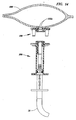
- Figures 13 and 14 illustrate an exemplary embodiment of a fluid system wherein a modified female connector 100 of the connector assembly is mounted directly to the wall of a container 600.
- the female connector 100 is different from the previously described female connectors 100.
- the female fitting 120 includes only the bracket 140.
- the bracket 140 may be variously configured.
- the bracket 140 may comprise a socket 145 or cup having any suitable plan form, for example, the representative bracket 140 in the illustrated embodiment comprises a generally C-shaped member.
- a female sealing member 170 may be disposed within the socket 145 of the bracket 140 to aid the sterile connection of the connection assembly as previously described.
- the proximal end of the female connector 100 may have a sealing layer, such as the previously described female stripout layer 300, to further aid the sterile connection of the connector assembly.
- the bracket 140 may also include a flange 142 with forks 146, as previously described, in order to aid the interlocking of the female connector 100 with the male connector 200.
- Alternative arrangements for the connection of the female and male connectors 100, 200 are also possible, and may include, for example, threaded connectors.
- the fitting 120 of the female connector 100 may extend beyond the container wall into the interior of the container 600.
- the female connector 100 may be connected to the wall of the container 600 by a variety of means. In the exemplary embodiment illustrated in Figure 13, the female connector 100 is connected to a major surface of the container 600.
- the female connector 100 may be bonded or welded to the container 600 or may be formed integrally therewith.
- the area of the wall where the female connector 100 is connected may be reinforced so that the female connector 100 will not tear away a portion of the wall.
- the reinforcement may be in the form of a grommet or any other suitable reinforcement means.
- the male and female connectors 200, 100 of the fluid system of Figures 13 and 14 may be interlocked as previously described. Once interlocked, the stripout layers 300, 310 are removed, and the stem 210 is moved through the male fitting 220 and sealing member 270, through the female sealing member 170 and an aperture 132a in the female fitting 120, and through the wall of the container 600, thereby forming a sterile fluid path therethrough.
- the head 250 of the stem 210 may include a piercing member.
- the aperture 132a may be sized to seal against the head 250 of the stem 210, which is preferably tapered to provide an increasingly snug fit and seal at the walls of the bracket 140 defining the aperture 132a.
- the female connector 100 may comprise an O-ring to provide a fluid tight seal between the head 250 and the aperture 132a.
- the connector assembly of any of the previous embodiments can be used to make either a wet connection or a dry connection, although preferably it is used to make a dry connection.
- a wet connection is one in which the male and female connectors 100, 200 are joined while there is liquid in one or both of the connectors 100, 200.
- a dry connection is one in which the connectors 100, 200 are joined without liquid in the connectors 100, 200, and the fluid flow through the connectors 100, 200 is established after the connectors 100, 200 are joined.
- a fluid blocking mechanism may be used to block fluid flow from a fluid source to a connector 100, 200 before the connectors 100, 200 are joined and to open fluid flow after the connectors 100, 200 are joined.
- the fluid blocking mechanism may be any device which can block and open fluid flow to a connector 100, 200.
- the fluid blocking mechanism may be operatively associated with the connector 100, 200, disposed between the connector 100, 200 and the fluid source, or operatively associated with the fluid source. If only one connector 100, 200 is connected to a fluid source, only one fluid blocking mechanism may be used. On the other hand, if both connectors 100, 200 are connected to a fluid source, two fluid blocking mechanisms may be used.
- a flow blocking mechanism 710, 720 is associated with the tubing 10, 20 attached to each of the male and the female connectors 100, 200.
- the flow blocking mechanism 710, 720 is preferably placed a short distance from the male and the female connectors 100, 200, e.g., within about 5 inches or more.
- the flow blocking mechanism 710, 720 can be any device which can selectively open and block the fluid flow to the connectors 100, 200, such as a valve or a clamp mounted to the exterior of the tubing 10, 20 and pinching the tubing 10, 20 closed. More preferably, the flow blocking mechanism 710, 720 is a breakaway type mechanism disposed in the interior of the tubing 10, 20.
- the breakaway type mechanism normally blocks fluid flow. However, when it is pinched, bent or otherwise manipulated by an operator, a portion of the mechanism moves, e.g., breaks away, and allows fluid flow through the mechanism.
- a breakaway type mechanism is disclosed in United States Patent No. 4,586,928 , which is incorporated by reference to support this and other features of the present invention.
- the flow blocking mechanism 710, 720 is arranged such that no liquid flows past the mechanism 710, 720 to the connector 100, 200. Consequently, neither the male nor the female connector 100, 200 has any liquid in it as they are joined.
- the connectors 100, 200 are joined as previously described such that they are locked together with the head 250 of the stem 210 securely inserted within the aperture 132 of the female fitting 100.
- the flow blocking mechanism 710, 720 is then opened to allow fluid flow through the connector assembly.
Applications Claiming Priority (3)
| Application Number | Priority Date | Filing Date | Title |
|---|---|---|---|
| US4605197P | 1997-05-09 | 1997-05-09 | |
| EP98921143A EP0981389B1 (de) | 1997-05-09 | 1998-05-08 | Verbindungsanordnung, fluidsysteme und methode zum erstellen einer verbindung |
| EP02079936A EP1297861B1 (de) | 1997-05-09 | 1998-05-08 | Verbindungsanordnungen, Fluidsysteme |
Related Parent Applications (1)
| Application Number | Title | Priority Date | Filing Date |
|---|---|---|---|
| EP02079936A Division EP1297861B1 (de) | 1997-05-09 | 1998-05-08 | Verbindungsanordnungen, Fluidsysteme |
Publications (2)
| Publication Number | Publication Date |
|---|---|
| EP1716885A2 true EP1716885A2 (de) | 2006-11-02 |
| EP1716885A3 EP1716885A3 (de) | 2006-11-15 |
Family
ID=21941317
Family Applications (4)
| Application Number | Title | Priority Date | Filing Date |
|---|---|---|---|
| EP06076411A Withdrawn EP1716885A3 (de) | 1997-05-09 | 1997-05-09 | Verbindungsanordnungen, Fluidsysteme und Methoden zum Erstellen einer Verbindung |
| EP02077861A Withdrawn EP1260245A3 (de) | 1997-05-09 | 1998-05-08 | Verbindungsanordnungen, Fluidsysteme, und Methoden zum Erstellen einer Verbindung |
| EP02079936A Expired - Lifetime EP1297861B1 (de) | 1997-05-09 | 1998-05-08 | Verbindungsanordnungen, Fluidsysteme |
| EP98921143A Expired - Lifetime EP0981389B1 (de) | 1997-05-09 | 1998-05-08 | Verbindungsanordnung, fluidsysteme und methode zum erstellen einer verbindung |
Family Applications After (3)
| Application Number | Title | Priority Date | Filing Date |
|---|---|---|---|
| EP02077861A Withdrawn EP1260245A3 (de) | 1997-05-09 | 1998-05-08 | Verbindungsanordnungen, Fluidsysteme, und Methoden zum Erstellen einer Verbindung |
| EP02079936A Expired - Lifetime EP1297861B1 (de) | 1997-05-09 | 1998-05-08 | Verbindungsanordnungen, Fluidsysteme |
| EP98921143A Expired - Lifetime EP0981389B1 (de) | 1997-05-09 | 1998-05-08 | Verbindungsanordnung, fluidsysteme und methode zum erstellen einer verbindung |
Country Status (8)
| Country | Link |
|---|---|
| US (5) | US6655655B1 (de) |
| EP (4) | EP1716885A3 (de) |
| JP (1) | JP2002510996A (de) |
| AT (2) | ATE255934T1 (de) |
| AU (1) | AU751476B2 (de) |
| CA (3) | CA2683227C (de) |
| DE (2) | DE69835967T2 (de) |
| WO (1) | WO1998050105A1 (de) |
Cited By (2)
| Publication number | Priority date | Publication date | Assignee | Title |
|---|---|---|---|---|
| US8671964B2 (en) | 2010-04-05 | 2014-03-18 | Daniel Py | Aseptic connector with deflectable ring of concern and method |
| US10426701B2 (en) | 2016-01-19 | 2019-10-01 | Medinstill Development Llc | Single use connectors |
Families Citing this family (105)
| Publication number | Priority date | Publication date | Assignee | Title |
|---|---|---|---|---|
| EP1716885A3 (de) * | 1997-05-09 | 2006-11-15 | Pall Corporation | Verbindungsanordnungen, Fluidsysteme und Methoden zum Erstellen einer Verbindung |
| SE0001278L (sv) * | 2000-04-06 | 2001-10-08 | Peter Unger Med P U Med Konsul | Sterilkoppling |
| ATE349239T1 (de) | 2002-04-26 | 2007-01-15 | Gl Tool And Mfg Co Inc | Ventil |
| US7507226B2 (en) | 2002-10-22 | 2009-03-24 | Baxter International Inc. | Access port with safety tab and fluid container employing same |
| US7942861B2 (en) | 2002-10-22 | 2011-05-17 | Baxter International Inc. | Fluid container with access port and safety cap |
| JP2004355987A (ja) * | 2003-05-30 | 2004-12-16 | Nec Corp | 防水型モジュラコネクタ |
| US8636721B2 (en) | 2003-11-20 | 2014-01-28 | Henry M. Jackson Foundation For The Advancement Of Military Medicine, Inc. | Portable hand pump for evacuation of fluids |
| US7293477B2 (en) | 2003-12-23 | 2007-11-13 | Millipore Corporation | Disposable, pre-sterilized fluid receptacle sampling device |
| ATE540721T1 (de) * | 2004-03-26 | 2012-01-15 | Cook Medical Technologies Llc | Verfahren und gerät für eine verbesserte luer- verbindung |
| BRPI0510291A (pt) * | 2004-04-27 | 2007-10-30 | Baxter Int | sistema de reator com tanque agitado |
| US7520919B2 (en) * | 2004-06-22 | 2009-04-21 | Gambro Lundia Ab | Transducer-protector device for medical apparatus |
| US8337475B2 (en) | 2004-10-12 | 2012-12-25 | C. R. Bard, Inc. | Corporeal drainage system |
| US7396051B2 (en) * | 2005-01-14 | 2008-07-08 | Baxa Corporation | Swabable fluid connectors and fluid connector pairs |
| SE527050C2 (sv) * | 2005-03-04 | 2005-12-13 | Novaseptic Ab | Metod och don för kontaminationssäker och/eller steril tätning mellan åtminstone två med varandra hopkopplingsbara kopplingsorgan |
| DK1893253T3 (da) * | 2005-03-23 | 2010-08-16 | Biosafe Sa | Integreret system til opsamling, forarbejdning og transplantation af celledelmængder, omfattende voksenstamceller til regenerativ medicin |
| US7261559B2 (en) * | 2005-04-01 | 2007-08-28 | Ultradent Products, Inc. | Syringe delivery system for dispensing a dental composite or other highly viscous material |
| DE102005020648A1 (de) | 2005-05-03 | 2006-11-16 | Sartorius Ag | Verbinder, Verbindersystem und Verwendung |
| WO2007038643A1 (en) | 2005-09-26 | 2007-04-05 | C.R. Bard, Inc. | Catheter connection systems |
| DE102006001623B4 (de) * | 2006-01-11 | 2009-05-07 | Sartorius Stedim Biotech Gmbh | Behälter und Verfahren zum Mischen von Medien |
| US9895526B2 (en) | 2006-03-08 | 2018-02-20 | Ivaxis, Llc | Anti-contamination cover for fluid connections |
| US7780794B2 (en) | 2006-07-21 | 2010-08-24 | Ivera Medical Corporation | Medical implement cleaning device |
| US8221363B2 (en) | 2006-10-18 | 2012-07-17 | Baxter Healthcare S.A. | Luer activated device with valve element under tension |
| US7981090B2 (en) | 2006-10-18 | 2011-07-19 | Baxter International Inc. | Luer activated device |
| US7753338B2 (en) | 2006-10-23 | 2010-07-13 | Baxter International Inc. | Luer activated device with minimal fluid displacement |
| FR2911493B1 (fr) * | 2007-01-24 | 2009-03-13 | Technoflex Sa | Procede et set de transfert d'un fluide entre deux recipients. |
| US7918243B2 (en) * | 2007-02-01 | 2011-04-05 | Saint-Gobain Performance Plastics Corporation | Connector assembly |
| US8899267B2 (en) * | 2007-02-01 | 2014-12-02 | Saint-Gobain Performance Plastics Corporation | Connector assembly |
| US9259284B2 (en) | 2007-02-12 | 2016-02-16 | 3M Innovative Properties Company | Female Luer connector disinfecting cap |
| US8469931B2 (en) | 2007-03-12 | 2013-06-25 | Gambro Lundia Ab | Medical product, and a method of handling a medical system |
| US8357143B2 (en) | 2007-03-12 | 2013-01-22 | Gambro Lundia Ab | Medical product, and a method of sterilizing a medical product |
| EP2167637B1 (de) * | 2007-06-16 | 2016-08-10 | Pall Technology UK Limited | Bioreaktorsondenverbindungssystem |
| FR2923541B1 (fr) * | 2007-11-13 | 2009-12-11 | Snecma | Vanne de decharge dans une turbomachine |
| SG153002A1 (en) | 2007-11-16 | 2009-06-29 | Millipore Corp | Fluid transfer device |
| US8323251B2 (en) | 2008-01-14 | 2012-12-04 | Fenwal, Inc. | Phlebotomy needle assembly and frangible cover |
| US20090204080A1 (en) * | 2008-02-12 | 2009-08-13 | Baxter International Inc. | Two-way valve connector |
| EP2586470B1 (de) * | 2008-02-14 | 2020-07-15 | KCI Licensing, Inc. | Vorrichtungen zur Behandlung von geschädigtem Gewebe |
| US8079492B2 (en) * | 2008-03-25 | 2011-12-20 | Meissner Filtration Products, Inc. | Disposable containers and method of making the same |
| EP2110149B1 (de) * | 2008-03-28 | 2017-05-03 | Fenwal, Inc. | Flügelnadelanordnung und zerbrechliche Hülle |
| US8435217B2 (en) * | 2008-04-11 | 2013-05-07 | Applied Silicone Corporation | Gas sterilizable two-part polymer delivery system |
| US8172823B2 (en) | 2008-07-03 | 2012-05-08 | Baxter International Inc. | Port assembly for use with needleless connector |
| US7905873B2 (en) | 2008-07-03 | 2011-03-15 | Baxter International Inc. | Port assembly for use with needleless connector |
| US7959192B2 (en) | 2008-07-09 | 2011-06-14 | Pall Corporation | Disconnectable connector assembly |
| FR2934337B1 (fr) | 2008-07-23 | 2010-09-17 | Millipore Corp | Dispositifs de raccordement et systeme de raccordement male-femelle les comportant |
| US8062280B2 (en) | 2008-08-19 | 2011-11-22 | Baxter Healthcare S.A. | Port assembly for use with needleless connector |
| US8145652B2 (en) * | 2008-10-09 | 2012-03-27 | International Business Machines Corporation | Automated propagation of non-conflicting queries in distributed databases |
| FR2940439B1 (fr) | 2008-12-18 | 2011-02-11 | Millipore Corp | Dispositif pour le transfert d'un milieu |
| FR2940440B1 (fr) | 2008-12-18 | 2010-12-24 | Millipore Corp | Dispositif pour le transfert d'un milieu |
| CN102405369B (zh) * | 2009-03-16 | 2016-04-20 | 考尔得产品公司 | 无菌联接装置 |
| US8394080B2 (en) | 2009-05-14 | 2013-03-12 | Baxter International Inc. | Needleless connector with slider |
| US8544497B2 (en) | 2009-10-30 | 2013-10-01 | Emd Millipore Corporation | Fluid transfer device and system |
| WO2011108679A1 (ja) * | 2010-03-03 | 2011-09-09 | 株式会社 エクセル電子 | 電子機器の接続器具及び接続装置 |
| EP2552496A4 (de) * | 2010-03-26 | 2013-12-04 | Ge Healthcare Bio Sciences | Sterilisierungsverfahren |
| DE102010028592B4 (de) * | 2010-05-05 | 2014-11-13 | Lisa Dräxlmaier GmbH | Tülle sowie Verfahren zur Herstellung einer solchen Tülle |
| US8454059B2 (en) | 2010-09-13 | 2013-06-04 | Pall Corporation | Connector assemblies, fluid systems including connector assemblies, and procedures for making fluid connections |
| JP2013540564A (ja) * | 2010-10-25 | 2013-11-07 | ユニバーシティ・オブ・カンザス | 薬剤容器の汚染防止用薬剤接触器材 |
| US8608369B2 (en) | 2011-01-07 | 2013-12-17 | Hyclone Laboratories, Inc. | Methods and systems for heating and mixing fluids |
| US9314751B2 (en) | 2011-01-07 | 2016-04-19 | Life Technologies Corporation | Methods and apparatus for mixing and shipping fluids |
| GB201103068D0 (en) | 2011-02-22 | 2011-04-06 | The Technology Partnership | Aseptic sampling system |
| CN102261361B (zh) * | 2011-04-14 | 2013-03-13 | 北京民海生物科技有限公司 | 一种玻璃接头用固定装置 |
| JP6121994B2 (ja) | 2011-06-08 | 2017-04-26 | ネクステージ メディカル インコーポレイテッド | 流体結合システム |
| CN103687790B (zh) | 2011-07-11 | 2016-04-13 | 海克隆实验室公司 | 流体歧管系统 |
| US9891080B2 (en) | 2011-10-28 | 2018-02-13 | Ge Healthcare Bio-Sciences Corp. | Probe assembly |
| WO2013067011A1 (en) | 2011-11-01 | 2013-05-10 | Indrani Deo | Aseptic connector for a free-flowing food |
| SG192310A1 (en) | 2012-02-02 | 2013-08-30 | Becton Dickinson Holdings Pte Ltd | Adaptor for coupling to a medical container |
| CN107261318B (zh) * | 2012-02-15 | 2020-12-08 | 可得制品公司 | 无菌性联结装置 |
| WO2013158312A1 (en) | 2012-04-18 | 2013-10-24 | Hyclone Laboratories, Inc. | Methods and apparatus for gas stream mass transfer with a liquid |
| US9364653B2 (en) | 2012-04-27 | 2016-06-14 | Colder Products Company | Aseptic coupling devices |
| WO2013184716A1 (en) | 2012-06-04 | 2013-12-12 | Ivera Medical Corporation | Male medical implement cleaning device |
| WO2014042827A2 (en) | 2012-09-17 | 2014-03-20 | Hyclone Laboratories, Inc. | Fluid manifold system with rotatable port assembly |
| JP5958861B2 (ja) * | 2013-01-18 | 2016-08-02 | エイブル株式会社 | 培養装置 |
| US9907617B2 (en) | 2013-03-15 | 2018-03-06 | 3M Innovative Properties Company | Medical implement cleaning device |
| CA2983222C (en) | 2013-03-29 | 2019-05-07 | Emd Millipore Corporation | Sterile connection/disconnection coupling and method |
| FR3007816B1 (fr) * | 2013-06-28 | 2016-02-05 | Sartorius Stedim Biotech | Connecteur fluidique asexue avec collier et protection. |
| WO2015013188A1 (en) | 2013-07-23 | 2015-01-29 | Colder Products Company | Aseptic coupling devices |
| CN105682732B (zh) * | 2013-11-07 | 2019-06-07 | 通用电气健康护理生物科学股份公司 | 用于无菌连接的连接器 |
| US8979357B1 (en) | 2014-03-17 | 2015-03-17 | Advanced Scientifics, Inc. | Transportable mixing system for biological and pharmaceutical materials |
| US9186493B2 (en) | 2014-04-15 | 2015-11-17 | Advanced Scientific, Inc. | Aseptic connector |
| US9346578B2 (en) | 2014-05-30 | 2016-05-24 | Finesse Solutions, Inc. | Aseptic connectors for bio-processing containers |
| SG11201610017SA (en) | 2014-05-30 | 2016-12-29 | Finesse Solutions Inc | Aseptic connectors for bio-processing containers |
| GB201415636D0 (en) | 2014-08-08 | 2014-10-22 | Ge Healthcare Bio Sciences | Sterile sensor insertion |
| US9731239B2 (en) | 2014-12-15 | 2017-08-15 | W. L. Gore & Associates, Inc. | Fluoropolymer article for bacterial filtration |
| US9987416B2 (en) * | 2015-01-09 | 2018-06-05 | BioQuiddity Inc. | Sterile assembled liquid medicament dosage control and delivery device |
| WO2016122732A1 (en) * | 2015-01-30 | 2016-08-04 | Emd Millipore Corporation | Fluid transfer device, system and method |
| US20180161568A1 (en) * | 2015-07-17 | 2018-06-14 | Parker-Hannifin Corporation | Sterile fluid connection |
| US10655768B2 (en) | 2015-08-13 | 2020-05-19 | Site Saver, Inc. | Breakaway connector |
| US10350400B2 (en) | 2015-09-20 | 2019-07-16 | Erbi Biosystems, Inc. | Apparatus and methods for aseptic fluid interconnects |
| WO2017210161A1 (en) * | 2016-06-01 | 2017-12-07 | Jerry Shevitz | Device for aseptically connecting large bore tubing |
| AU2017299466B2 (en) | 2016-07-18 | 2022-07-14 | Merit Medical Systems, Inc. | Inflatable radial artery compression device |
| DE102016120699B3 (de) | 2016-10-28 | 2018-03-08 | Trace Analytics Gmbh | Sonde mit zwei Entnahmeöffnungen |
| KR101830593B1 (ko) | 2017-01-09 | 2018-02-21 | 최형찬 | 카테터 안전 고정장치 |
| US20190076325A1 (en) * | 2017-09-14 | 2019-03-14 | Mikael NAYGAUZ | Devices and systems with an internal displacement mechanism for contaminant-free engagement of medical vessels and devices |
| US11633584B2 (en) * | 2017-09-20 | 2023-04-25 | Miltenyi Biotec Gmbh | Sterile connector |
| DK3502229T3 (da) | 2017-12-22 | 2022-08-08 | Evologic Tech Gmbh | Inokuleringsbeholder og bioreaktor til hårrodskulturer |
| USD851759S1 (en) | 2018-01-17 | 2019-06-18 | Site Saver, Inc. | Breakaway connector for medical lines |
| US11293003B2 (en) | 2018-01-17 | 2022-04-05 | Life Technologies Corporation | Configurable fluid mixing system housing and support hardware |
| EP3740273A4 (de) | 2018-01-19 | 2021-10-20 | Site Saver, Inc. | Abreissbarer medizinischer schlauchverbinder |
| US11590333B2 (en) | 2018-01-22 | 2023-02-28 | Saint-Gobain Performance Plastics Corporation | Tubular coupling |
| EP3539596A1 (de) * | 2018-03-15 | 2019-09-18 | Tecpharma Licensing AG | Anordnung für eine injektions- oder infusionsvorrichtung |
| EP3539592A1 (de) * | 2018-03-15 | 2019-09-18 | Tecpharma Licensing AG | Injektions- oder infusionsvorrichtung mit einem verbesserten gehäuse und trennschicht zur beseitigung von sterilen barrierefolien unter verwendung der trennschicht |
| CN114585411A (zh) | 2019-08-27 | 2022-06-03 | 考尔得产品公司 | 一次性无性无菌流体联接器 |
| US11415255B1 (en) * | 2020-03-31 | 2022-08-16 | Colder Products Company | Aseptic fluid couplings |
| WO2022005512A1 (en) | 2020-06-29 | 2022-01-06 | Colder Products Company | Aseptic fluid couplings |
| US11965613B2 (en) * | 2020-10-27 | 2024-04-23 | Zeta Gmbh | System and a method for providing a sterile fluid connection between a first fluid channel and a second fluid channel |
| AT524366A1 (de) * | 2020-10-27 | 2022-05-15 | Zeta Gmbh | System und verfahren zur bereitstellung einer sterilen fluidverbindung zwischen einem ersten fluidkanal und einem zweiten fluidkanal |
| FR3117569B1 (fr) * | 2020-12-16 | 2022-11-25 | Parker Hannifin Emea Sarl | Dispositif de raccordement aseptique d’un tube |
Citations (6)
| Publication number | Priority date | Publication date | Assignee | Title |
|---|---|---|---|---|
| US4019512A (en) * | 1975-12-04 | 1977-04-26 | Tenczar Francis J | Adhesively activated sterile connector |
| US4030494A (en) * | 1973-11-05 | 1977-06-21 | Francis Tenczar | Fluid connectors |
| DE3210964A1 (de) * | 1982-03-25 | 1983-10-06 | Wolf Dipl Ing Henning | Sterile verschluss- und kupplungseinheit |
| US4636204A (en) * | 1982-04-13 | 1987-01-13 | Gambro Lundia Ab | Coupling for the connection of flexible tubes and the like |
| US5492147A (en) * | 1995-01-17 | 1996-02-20 | Aeroquip Corporation | Dry break coupling |
| WO1996030076A1 (en) * | 1995-03-31 | 1996-10-03 | Pall Corporation | Connector assembly |
Family Cites Families (127)
| Publication number | Priority date | Publication date | Assignee | Title |
|---|---|---|---|---|
| US3202442A (en) | 1961-05-19 | 1965-08-24 | Aeroquip Corp | Coupling |
| DE1929522U (de) | 1962-08-29 | 1965-12-23 | Herbert Dr Med Makowsky | Zahnbuerste. |
| FR1380396A (fr) | 1964-01-30 | 1964-11-27 | Chatleff Controls | Dispositif d'accouplement pour tuyaux |
| US3306563A (en) * | 1964-07-31 | 1967-02-28 | Soto Ricardo Hurtado | Aseptic draining and support means for flexible bags |
| ES319553A1 (es) | 1964-11-17 | 1966-05-01 | Projecteurs Cibiei | Un conjunto de acoplamientos para elementos de circuito hidraulico. |
| US3685795A (en) | 1970-07-06 | 1972-08-22 | Baxter Laboratories Inc | Fluid flow valve |
| US3784235A (en) | 1971-10-08 | 1974-01-08 | Us Navy | Tubular adhesive joint with snap lock |
| GB1428391A (en) | 1972-06-23 | 1976-03-17 | Avon Medicals | Couplings |
| US3909910A (en) * | 1973-03-29 | 1975-10-07 | Union Carbide Corp | Method of joining the ends of two conduits together in a sterile manner |
| US3865411A (en) * | 1973-03-29 | 1975-02-11 | Union Carbide Corp | Sterile connector for conduits |
| US3986508A (en) | 1973-08-22 | 1976-10-19 | Abcor, Inc. | Sterilizable, medical connector for blood processing |
| US3890971A (en) | 1973-10-23 | 1975-06-24 | Thomas A Leeson | Safety syringe |
| US4022205A (en) | 1973-11-05 | 1977-05-10 | Tenczar Francis J | Fluid connectors |
| US3968195A (en) | 1974-06-17 | 1976-07-06 | Marilyn Bishop | Method for making sterile connections |
| US4022496A (en) | 1975-03-31 | 1977-05-10 | Aeroquip Corporation | Frangible diaphragm refrigeration coupling |
| US4080965A (en) | 1976-09-30 | 1978-03-28 | Baxter Travenol Laboratories, Inc. | In-line cannula valve assembly |
| US4191225A (en) | 1976-10-20 | 1980-03-04 | Ims Limited | Pharmaceutical cocktail package |
| US4048997A (en) * | 1976-11-01 | 1977-09-20 | Mpl, Inc. | Syringe with actinic radiation protection |
| JPS5397293A (en) | 1977-02-04 | 1978-08-25 | Terumo Corp | Aseptic connector |
| US4149534A (en) * | 1977-05-06 | 1979-04-17 | Tenczar Francis J | Sterile film connectors |
| US4161949A (en) | 1977-10-27 | 1979-07-24 | Pennwalt Corporation | Aseptic connector |
| US4201208A (en) | 1977-11-30 | 1980-05-06 | Abbott Laboratories | Sterile connecting device |
| US4195632A (en) | 1978-05-03 | 1980-04-01 | Cutter Laboratories, Inc. | Fluid flow valve |
| US4508367A (en) | 1979-01-09 | 1985-04-02 | Oreopoulos Dimitrios G | Connector |
| US4265280A (en) | 1979-01-23 | 1981-05-05 | Baxter Travenol Laboratories, Inc. | Connector member for sealed conduits |
| US4256106A (en) | 1979-04-30 | 1981-03-17 | Becton, Dickinson And Company | Resealable device |
| US4334551A (en) | 1979-04-30 | 1982-06-15 | Becton Dickinson & Company | Connector |
| US4289337A (en) | 1979-05-23 | 1981-09-15 | Baxter Travenol Laboratories, Inc. | Tubing connection for containers generally utilizing dissimilar materials |
| US4336802A (en) | 1980-07-28 | 1982-06-29 | Baxter Travenol Laboratories, Inc. | Parenteral solution container for aseptic mixing |
| US4346833A (en) * | 1980-08-05 | 1982-08-31 | Daniel Bernhardt | Replaceable multiple seal package |
| US4368729A (en) | 1980-10-14 | 1983-01-18 | Baxter Travenol Laboratories, Inc. | Aseptic system for total parenteral nutrition and the like |
| US4418945A (en) | 1981-06-08 | 1983-12-06 | International Business Machines Corporation | Sterile connectors |
| US4458733A (en) | 1982-04-06 | 1984-07-10 | Baxter Travenol Laboratories, Inc. | Mixing apparatus |
| US4410321A (en) | 1982-04-06 | 1983-10-18 | Baxter Travenol Laboratories, Inc. | Closed drug delivery system |
| US4457749A (en) | 1982-04-19 | 1984-07-03 | Baxter Travenol Laboratories, Inc. | Shield for connectors |
| US4475548A (en) * | 1982-06-01 | 1984-10-09 | Rudolph Muto | Fitting for endotracheal tube apparatus and method of making the fitting |
| US4516971A (en) | 1982-07-06 | 1985-05-14 | Spencer Dudley W C | Sterile docking process, apparatus and system |
| US4507119A (en) | 1982-07-06 | 1985-03-26 | E. I. Du Pont De Nemours And Company | Sterile docking process, apparatus and system |
| US4443215A (en) | 1982-07-06 | 1984-04-17 | E. I. Du Pont De Nemours & Company | Sterile docking process, apparatus and system |
| US4521263A (en) | 1982-08-16 | 1985-06-04 | E. I. Du Pont De Nemours And Company | Automatic splicing device and process |
| US4680025A (en) | 1982-08-24 | 1987-07-14 | Baxter Travenol Laboratories, Inc. | Blood component collection systems and methods |
| US4488961A (en) | 1982-09-29 | 1984-12-18 | E. I. Du Pont De Nemours And Company | One-way filter unit |
| US4511359A (en) | 1982-09-29 | 1985-04-16 | Manresa, Inc. | Sterile connection device |
| US4531768A (en) | 1982-12-02 | 1985-07-30 | Forerank, Inc. | Pipe coupling |
| US4512766A (en) * | 1982-12-08 | 1985-04-23 | Whitman Medical Corporation | Catheter valve |
| US4752292A (en) | 1983-01-24 | 1988-06-21 | Icu Medical, Inc. | Medical connector |
| US5688254A (en) | 1983-01-24 | 1997-11-18 | Icu Medical, Inc. | Medical connector |
| NL8300386A (nl) | 1983-02-02 | 1984-09-03 | Steritech Bv | Inrichting voor het steriel met elkaar in verbinding stellen van twee kamers. |
| CA1215945A (en) | 1983-03-20 | 1986-12-30 | Bengt Gustavsson | Fluid transfer system |
| US4610670A (en) | 1983-06-13 | 1986-09-09 | E. I. Du Pont De Nemours And Company | Sterile connection process, apparatus and system |
| US4591049A (en) * | 1984-01-16 | 1986-05-27 | Kidde, Inc. | Hermetically sealed two-component mixing system |
| US4573978A (en) | 1984-03-15 | 1986-03-04 | Medrad, Inc. | Angiographic syringe and connector for joining a catheter thereto |
| US4828557A (en) | 1984-04-06 | 1989-05-09 | Persidsky Maxim D | Sterile connector and method |
| US4619640A (en) * | 1984-08-17 | 1986-10-28 | Potolsky Abraham I | Blood transfusion connector assembly |
| US4586928A (en) | 1984-10-09 | 1986-05-06 | Miles Laboratories, Inc. | Pivoting frangible valve for plastic bags |
| US4879098A (en) | 1985-01-25 | 1989-11-07 | Becton, Dickinson And Company | Device for the separation of the lighter fraction from the heavier fraction of a liquid sample |
| US4619642A (en) | 1985-03-12 | 1986-10-28 | E. I. Du Pont De Nemours And Company | Sterile, cold cut connection process, apparatus and system |
| DE3564191D1 (en) | 1985-07-05 | 1988-09-15 | Npbi Bv | Sterile docking process and apparatus for plastic tube portions or the like |
| ZA865673B (en) * | 1985-08-08 | 1988-03-30 | Pall Corp | Apparatus and method for reducing risk of contamination in delivering to a patient pharmaceutically acceptable material |
| US4617012A (en) | 1985-10-29 | 1986-10-14 | Manresa, Inc. | Sterile connector with movable connection member |
| EP0258579A1 (de) | 1986-08-01 | 1988-03-09 | Societe Des Produits Nestle S.A. | Vorrichtung zum Anschliessen und Entleeren von Verpackungen |
| US4840690A (en) | 1986-08-25 | 1989-06-20 | Becton, Dickinson And Company | Method of constructing a blood flow conduit |
| FR2606643A1 (fr) | 1986-11-17 | 1988-05-20 | Congio Gerard | Seringue rendue hors d'usage apres la premiere utilisation |
| US4816221A (en) | 1986-12-08 | 1989-03-28 | Baxter Travenol Laboratories, Inc. | Method of simultaneously assembling and sterilizing a unitary container and a fluid transfer set |
| FR2608250B1 (fr) | 1986-12-16 | 1989-02-24 | Peugeot | Raccord a fixation rapide |
| US4864101A (en) | 1987-01-09 | 1989-09-05 | Denco, Inc. | Hybrid welding wafer |
| US4753697A (en) | 1987-02-24 | 1988-06-28 | Denco, Inc. | Total-containment sterile process and system |
| FR2614386B1 (fr) | 1987-04-24 | 1989-08-18 | Lustig Cie Mecanique Serrureri | Dispositif de securite pour raccordement de tuyaux souples |
| US4792163A (en) | 1987-05-13 | 1988-12-20 | Baxter Travenol Laboratories, Inc. | Secondary lock for medical tube coupling |
| US4897138A (en) | 1987-05-18 | 1990-01-30 | Denco, Inc. | Sealing of plastic tubes |
| US4793880A (en) | 1987-05-18 | 1988-12-27 | Denco, Inc. | Sterile welding of plastic tubes |
| FR2617943B1 (fr) | 1987-07-06 | 1990-10-05 | Inventa Ag | Raccord rapide destine a relier une conduite flexible ou rigide |
| US4768568A (en) | 1987-07-07 | 1988-09-06 | Survival Technology, Inc. | Hazardous material vial apparatus providing expansible sealed and filter vented chambers |
| US4978446A (en) | 1987-08-26 | 1990-12-18 | Cobe Laboratories, Inc. | Sterile blood component collection |
| US4913756A (en) | 1987-09-22 | 1990-04-03 | Denco, Inc. | Techniques for welding thermoplastic tubes |
| US4933036A (en) | 1987-09-22 | 1990-06-12 | Denco, Inc. | Techniques for welding thermoplastic tubes |
| US4832773A (en) | 1987-09-22 | 1989-05-23 | Denco, Inc. | Techniques for welding thermoplastic tubes |
| US4770735A (en) | 1987-09-22 | 1988-09-13 | Denco, Inc. | Techniques for welding thermoplastic tubes |
| US4767400A (en) | 1987-10-27 | 1988-08-30 | Cordis Corporation | Porous ventricular catheter |
| US4838875A (en) | 1987-12-09 | 1989-06-13 | Somor Andrew T | Method and apparatus for dealing with intravenous fluids |
| ATE111339T1 (de) | 1988-06-02 | 1994-09-15 | Piero Marrucchi | Verfahren und vorrichtung zum behandeln und uebertragen von stoffen zwischen abgeschlossenen räumen. |
| US5104390A (en) * | 1988-09-01 | 1992-04-14 | Alza Corporation | Fluid receiving receptacle comprising biocide delivery system contacting outside of receptacle |
| US4898209A (en) * | 1988-09-27 | 1990-02-06 | Baxter International Inc. | Sliding reconstitution device with seal |
| US5017259A (en) | 1988-10-13 | 1991-05-21 | Terumo Kabushiki Kaisha | Preparation of catheter including bonding and then thermoforming |
| US4944728A (en) | 1988-10-17 | 1990-07-31 | Safe Medical Devices, Inc. | Intravenous catheter placement device |
| US4941517A (en) | 1988-10-20 | 1990-07-17 | Galloway Trust | Aseptic fluid transfer apparatus and methods |
| JPH0674875B2 (ja) | 1988-12-07 | 1994-09-21 | エムス − インヴエンタ・アクチエンゲゼルシヤフト | 迅速断ち継ぎ継手 |
| IT1233374B (it) | 1988-12-21 | 1992-03-27 | Mccarthy Martin M | Siringa monouso per iniezioni percutanee |
| CH677964A5 (en) | 1989-01-05 | 1991-07-15 | Inventa Ag | Rapid connection for pipe or hose - consists of core and housing with seal between and ring with pipe socket |
| US5374256A (en) * | 1989-06-16 | 1994-12-20 | Science Incorporated | Fluid container for use with a fluid delivery apparatus |
| US4998927A (en) | 1989-08-18 | 1991-03-12 | Vaillancourt Vincent L | Connector |
| US4950260A (en) | 1989-11-02 | 1990-08-21 | Safetyject | Medical connector |
| US4998921A (en) | 1989-11-20 | 1991-03-12 | Vickroy Harold C | Intermittent I.V. therapy needle sheath |
| US4998713A (en) | 1990-01-10 | 1991-03-12 | Vaillancourt Vincent L | Needle connector |
| DE4000764A1 (de) * | 1990-01-12 | 1991-07-18 | Braun Melsungen Ag | Ansatzstueck |
| JP2599011B2 (ja) | 1990-01-17 | 1997-04-09 | 株式会社大塚製薬工場 | コネクタ |
| US5122129A (en) | 1990-05-09 | 1992-06-16 | Olson Donald J | Sampler coupler device useful in the medical arts |
| GB2245670A (en) | 1990-06-27 | 1992-01-08 | Ford Motor Co | A pipe coupling |
| US5279591A (en) | 1990-07-16 | 1994-01-18 | Simon Alexander Z | Protector for needle catheter |
| US5067950A (en) | 1990-07-30 | 1991-11-26 | Johnson & Johnson Medical, Inc. | Wound drainage tube/reservoir connector |
| US5232454A (en) | 1990-08-01 | 1993-08-03 | Smiths Industries Medical Systems, Inc. | Safety needle container |
| US5195993A (en) | 1990-08-30 | 1993-03-23 | Arthur Gianakos | Needle protecting assembly |
| US5065783A (en) | 1990-09-20 | 1991-11-19 | George Braddock Ogle, II | Valve with self-sealing internal cannula |
| JPH0642676Y2 (ja) | 1990-11-15 | 1994-11-09 | 昭和電工株式会社 | 輸液バック |
| US5122123A (en) | 1991-01-30 | 1992-06-16 | Vaillancourt Vincent L | Closed system connector assembly |
| IT221835Z2 (it) | 1991-04-16 | 1994-12-06 | Mc Carthy Martin Charles | Siringa monouso autobloccante |
| AR243387A1 (es) | 1991-10-03 | 1993-08-31 | Cesar Gabriel Corsich | Jeringa hipodermica con embolo trabable para evitar su recarga y reutilizacion. |
| US5267972A (en) | 1992-07-20 | 1993-12-07 | Anderson Wayne W | Hypodermic syringe with needle guard |
| US5295972A (en) | 1992-08-04 | 1994-03-22 | Metatech Corporation | Hypodermic syringe with protective cap |
| US5279583A (en) | 1992-08-28 | 1994-01-18 | Shober Jr Robert C | Retractable injection needle assembly |
| US5393101A (en) * | 1992-10-02 | 1995-02-28 | Pall Corporation | Connector assembly |
| US5224936A (en) | 1992-10-15 | 1993-07-06 | Brian Gallagher | Automatic self-protecting hypodermic needle assembly |
| US5334180A (en) | 1993-04-01 | 1994-08-02 | Abbott Laboratories | Sterile formed, filled and sealed flexible container |
| ATA164293A (de) | 1993-08-17 | 1995-09-15 | Dieringer Franz A | Kupplung für die verbindung von schlauchleitungen |
| US5549568A (en) | 1994-08-22 | 1996-08-27 | Shields; Jack W. | Elastomeric needle shield and hub-cap |
| US5437639A (en) | 1994-09-19 | 1995-08-01 | Malenchek; Robert | Needle protective sheath device |
| US5653698A (en) | 1995-01-13 | 1997-08-05 | Sanofi Winthrop, Inc. | Coupling systems for saftey cannula |
| US5628726A (en) | 1995-02-16 | 1997-05-13 | Duxbury Scientific, Inc. | Blood collection system |
| US5839715A (en) | 1995-05-16 | 1998-11-24 | Alaris Medical Systems, Inc. | Medical adapter having needleless valve and sharpened cannula |
| IT1285266B1 (it) | 1996-02-26 | 1998-06-03 | Borla Ind | Connettore con valvola di protezione per linee medicali di infusione/ trasfusione e simili. |
| US5848997A (en) | 1996-03-15 | 1998-12-15 | Becton Dickinson And Company | Disconnect for medical access devices |
| US5738671A (en) | 1996-07-30 | 1998-04-14 | Bracco Diagnostics Inc. | Flexible plastic container for the containment and delivery of diagnostic contrast media and parenteral drug formulations |
| EP1716885A3 (de) * | 1997-05-09 | 2006-11-15 | Pall Corporation | Verbindungsanordnungen, Fluidsysteme und Methoden zum Erstellen einer Verbindung |
| SE512489C2 (sv) | 1997-07-14 | 2000-03-27 | Arom Pak Ab | Aseptisk anslutningsanordning |
| US6162206A (en) | 1997-12-23 | 2000-12-19 | Baxter International Inc. | Resealable access site |
| US5989240A (en) * | 1998-02-27 | 1999-11-23 | Becton, Dickson And Company | Adaptor for mounting a fluid handling device on a catheter tubing |
| US6517526B1 (en) * | 2000-12-29 | 2003-02-11 | Yehuda Tamari | Container for lyophilizing biological products |
-
1997
- 1997-05-09 EP EP06076411A patent/EP1716885A3/de not_active Withdrawn
-
1998
- 1998-05-08 EP EP02077861A patent/EP1260245A3/de not_active Withdrawn
- 1998-05-08 EP EP02079936A patent/EP1297861B1/de not_active Expired - Lifetime
- 1998-05-08 CA CA2683227A patent/CA2683227C/en not_active Expired - Lifetime
- 1998-05-08 DE DE69835967T patent/DE69835967T2/de not_active Expired - Lifetime
- 1998-05-08 EP EP98921143A patent/EP0981389B1/de not_active Expired - Lifetime
- 1998-05-08 AT AT98921143T patent/ATE255934T1/de not_active IP Right Cessation
- 1998-05-08 WO PCT/US1998/009653 patent/WO1998050105A1/en active Search and Examination
- 1998-05-08 US US09/423,374 patent/US6655655B1/en not_active Expired - Lifetime
- 1998-05-08 JP JP54858498A patent/JP2002510996A/ja active Pending
- 1998-05-08 AT AT02079936T patent/ATE339986T1/de not_active IP Right Cessation
- 1998-05-08 AU AU73818/98A patent/AU751476B2/en not_active Expired
- 1998-05-08 DE DE69820433T patent/DE69820433T2/de not_active Expired - Lifetime
- 1998-05-08 CA CA2655564A patent/CA2655564C/en not_active Expired - Lifetime
- 1998-05-08 CA CA002289230A patent/CA2289230C/en not_active Expired - Lifetime
-
2003
- 2003-10-16 US US10/685,431 patent/US6880801B2/en not_active Expired - Lifetime
-
2004
- 2004-08-31 US US10/929,769 patent/US7090191B2/en not_active Expired - Lifetime
-
2006
- 2006-04-28 US US11/412,981 patent/US7523918B2/en not_active Expired - Fee Related
-
2007
- 2007-10-31 US US11/931,047 patent/US8607432B2/en not_active Expired - Fee Related
Patent Citations (6)
| Publication number | Priority date | Publication date | Assignee | Title |
|---|---|---|---|---|
| US4030494A (en) * | 1973-11-05 | 1977-06-21 | Francis Tenczar | Fluid connectors |
| US4019512A (en) * | 1975-12-04 | 1977-04-26 | Tenczar Francis J | Adhesively activated sterile connector |
| DE3210964A1 (de) * | 1982-03-25 | 1983-10-06 | Wolf Dipl Ing Henning | Sterile verschluss- und kupplungseinheit |
| US4636204A (en) * | 1982-04-13 | 1987-01-13 | Gambro Lundia Ab | Coupling for the connection of flexible tubes and the like |
| US5492147A (en) * | 1995-01-17 | 1996-02-20 | Aeroquip Corporation | Dry break coupling |
| WO1996030076A1 (en) * | 1995-03-31 | 1996-10-03 | Pall Corporation | Connector assembly |
Cited By (3)
| Publication number | Priority date | Publication date | Assignee | Title |
|---|---|---|---|---|
| US8671964B2 (en) | 2010-04-05 | 2014-03-18 | Daniel Py | Aseptic connector with deflectable ring of concern and method |
| US9726314B2 (en) | 2010-04-05 | 2017-08-08 | Dr. Py Institute Llc | Aseptic connector with deflectable ring of concern and method |
| US10426701B2 (en) | 2016-01-19 | 2019-10-01 | Medinstill Development Llc | Single use connectors |
Also Published As
| Publication number | Publication date |
|---|---|
| CA2683227C (en) | 2013-01-29 |
| EP1260245A3 (de) | 2002-12-11 |
| CA2655564C (en) | 2010-10-19 |
| CA2289230A1 (en) | 1998-11-12 |
| US6880801B2 (en) | 2005-04-19 |
| US20060192165A1 (en) | 2006-08-31 |
| EP0981389A1 (de) | 2000-03-01 |
| DE69835967D1 (de) | 2006-11-02 |
| DE69820433T2 (de) | 2004-12-02 |
| ATE255934T1 (de) | 2003-12-15 |
| EP1297861B1 (de) | 2006-09-20 |
| US20080048436A1 (en) | 2008-02-28 |
| EP1260245A2 (de) | 2002-11-27 |
| DE69835967T2 (de) | 2007-09-20 |
| CA2289230C (en) | 2009-07-14 |
| JP2002510996A (ja) | 2002-04-09 |
| EP0981389B1 (de) | 2003-12-10 |
| US8607432B2 (en) | 2013-12-17 |
| ATE339986T1 (de) | 2006-10-15 |
| CA2683227A1 (en) | 1998-11-12 |
| AU751476B2 (en) | 2002-08-15 |
| EP1297861A1 (de) | 2003-04-02 |
| AU7381898A (en) | 1998-11-27 |
| US7090191B2 (en) | 2006-08-15 |
| US20050054238A1 (en) | 2005-03-10 |
| CA2655564A1 (en) | 1998-11-12 |
| EP1716885A3 (de) | 2006-11-15 |
| US20040171302A1 (en) | 2004-09-02 |
| US7523918B2 (en) | 2009-04-28 |
| WO1998050105A1 (en) | 1998-11-12 |
| DE69820433D1 (de) | 2004-01-22 |
| US6655655B1 (en) | 2003-12-02 |
Similar Documents
| Publication | Publication Date | Title |
|---|---|---|
| US6655655B1 (en) | Connector assemblies, fluid systems, and methods for making a connection | |
| US6341802B1 (en) | Fluid delivery systems and methods and assemblies for making connections | |
| KR101378877B1 (ko) | 커넥터 조립체, 커넥터 조립체를 포함하는 유체 시스템, 및 유체 연결을 이루기 위한 방법 | |
| CA2101826C (en) | Connector assembly | |
| CN107255198B (zh) | 无菌性联结装置 | |
| EP0858589B1 (de) | Vorrichtung zur einführung und/oder entnahme eines mediums in einen/aus einem behälter | |
| JPS62155862A (ja) | 汚染防止接続装置 | |
| AU734259B2 (en) | connector assembly | |
| AU733299B2 (en) | Connector assembly |
Legal Events
| Date | Code | Title | Description |
|---|---|---|---|
| PUAI | Public reference made under article 153(3) epc to a published international application that has entered the european phase |
Free format text: ORIGINAL CODE: 0009012 |
|
| PUAL | Search report despatched |
Free format text: ORIGINAL CODE: 0009013 |
|
| AC | Divisional application: reference to earlier application |
Ref document number: 1297861 Country of ref document: EP Kind code of ref document: P Ref document number: 0981389 Country of ref document: EP Kind code of ref document: P |
|
| AK | Designated contracting states |
Kind code of ref document: A2 Designated state(s): AT BE CH DE DK ES FI FR GB IE IT LI NL PT SE |
|
| AK | Designated contracting states |
Kind code of ref document: A3 Designated state(s): AT BE CH DE DK ES FI FR GB IE IT LI NL PT SE |
|
| 17P | Request for examination filed |
Effective date: 20070213 |
|
| 17Q | First examination report despatched |
Effective date: 20070316 |
|
| AKX | Designation fees paid |
Designated state(s): AT BE CH DE DK ES FI FR GB IE IT LI NL PT SE |
|
| STAA | Information on the status of an ep patent application or granted ep patent |
Free format text: STATUS: THE APPLICATION IS DEEMED TO BE WITHDRAWN |
|
| 18D | Application deemed to be withdrawn |
Effective date: 20071201 |