EP1716043B1 - Procede et systeme de test d'un systeme de commande d'un batiment de mer - Google Patents
Procede et systeme de test d'un systeme de commande d'un batiment de mer Download PDFInfo
- Publication number
- EP1716043B1 EP1716043B1 EP04808880A EP04808880A EP1716043B1 EP 1716043 B1 EP1716043 B1 EP 1716043B1 EP 04808880 A EP04808880 A EP 04808880A EP 04808880 A EP04808880 A EP 04808880A EP 1716043 B1 EP1716043 B1 EP 1716043B1
- Authority
- EP
- European Patent Office
- Prior art keywords
- control system
- signals
- vessel
- control
- test
- Prior art date
- Legal status (The legal status is an assumption and is not a legal conclusion. Google has not performed a legal analysis and makes no representation as to the accuracy of the status listed.)
- Not-in-force
Links
- 238000000034 method Methods 0.000 title claims abstract description 93
- 238000012360 testing method Methods 0.000 title claims description 227
- 230000004044 response Effects 0.000 claims abstract description 83
- 238000005259 measurement Methods 0.000 claims description 59
- 238000004891 communication Methods 0.000 claims description 48
- 238000004422 calculation algorithm Methods 0.000 claims description 30
- 230000008859 change Effects 0.000 claims description 17
- 230000001133 acceleration Effects 0.000 claims description 15
- 238000004088 simulation Methods 0.000 claims description 15
- 230000006870 function Effects 0.000 claims description 13
- 238000009826 distribution Methods 0.000 claims description 6
- 238000012544 monitoring process Methods 0.000 claims description 6
- 108010076504 Protein Sorting Signals Proteins 0.000 claims description 4
- 230000015556 catabolic process Effects 0.000 claims description 2
- 230000005540 biological transmission Effects 0.000 claims 1
- 238000001914 filtration Methods 0.000 claims 1
- 238000005553 drilling Methods 0.000 description 41
- 230000033001 locomotion Effects 0.000 description 39
- 238000004519 manufacturing process Methods 0.000 description 11
- 238000012986 modification Methods 0.000 description 11
- 230000004048 modification Effects 0.000 description 11
- 238000011989 factory acceptance test Methods 0.000 description 9
- 230000008569 process Effects 0.000 description 9
- 239000003208 petroleum Substances 0.000 description 8
- 230000010354 integration Effects 0.000 description 6
- 230000009471 action Effects 0.000 description 4
- 230000008439 repair process Effects 0.000 description 4
- 230000008672 reprogramming Effects 0.000 description 4
- 238000001228 spectrum Methods 0.000 description 4
- 238000013016 damping Methods 0.000 description 3
- 238000013461 design Methods 0.000 description 3
- 238000009434 installation Methods 0.000 description 3
- 239000003921 oil Substances 0.000 description 3
- RZVHIXYEVGDQDX-UHFFFAOYSA-N 9,10-anthraquinone Chemical compound C1=CC=C2C(=O)C3=CC=CC=C3C(=O)C2=C1 RZVHIXYEVGDQDX-UHFFFAOYSA-N 0.000 description 2
- 238000013459 approach Methods 0.000 description 2
- 230000006399 behavior Effects 0.000 description 2
- 239000000498 cooling water Substances 0.000 description 2
- 238000005520 cutting process Methods 0.000 description 2
- 230000001934 delay Effects 0.000 description 2
- 230000000694 effects Effects 0.000 description 2
- 238000012423 maintenance Methods 0.000 description 2
- 230000001360 synchronised effect Effects 0.000 description 2
- XLYOFNOQVPJJNP-UHFFFAOYSA-N water Substances O XLYOFNOQVPJJNP-UHFFFAOYSA-N 0.000 description 2
- 101000666657 Homo sapiens Rho-related GTP-binding protein RhoQ Proteins 0.000 description 1
- 102100038339 Rho-related GTP-binding protein RhoQ Human genes 0.000 description 1
- 230000005534 acoustic noise Effects 0.000 description 1
- 238000004590 computer program Methods 0.000 description 1
- 238000005094 computer simulation Methods 0.000 description 1
- 238000010276 construction Methods 0.000 description 1
- 238000012937 correction Methods 0.000 description 1
- 238000011161 development Methods 0.000 description 1
- 230000018109 developmental process Effects 0.000 description 1
- 230000005284 excitation Effects 0.000 description 1
- 238000012949 factory acceptance testing Methods 0.000 description 1
- 239000012530 fluid Substances 0.000 description 1
- 239000011888 foil Substances 0.000 description 1
- 239000000446 fuel Substances 0.000 description 1
- 230000036541 health Effects 0.000 description 1
- 230000002706 hydrostatic effect Effects 0.000 description 1
- 238000013101 initial test Methods 0.000 description 1
- 238000007689 inspection Methods 0.000 description 1
- 230000007774 longterm Effects 0.000 description 1
- 239000010687 lubricating oil Substances 0.000 description 1
- 238000013178 mathematical model Methods 0.000 description 1
- 238000005086 pumping Methods 0.000 description 1
- 230000008054 signal transmission Effects 0.000 description 1
- 238000012546 transfer Methods 0.000 description 1
- 238000012795 verification Methods 0.000 description 1
Images


Classifications
-
- B—PERFORMING OPERATIONS; TRANSPORTING
- B63—SHIPS OR OTHER WATERBORNE VESSELS; RELATED EQUIPMENT
- B63H—MARINE PROPULSION OR STEERING
- B63H25/00—Steering; Slowing-down otherwise than by use of propulsive elements; Dynamic anchoring, i.e. positioning vessels by means of main or auxiliary propulsive elements
-
- G—PHYSICS
- G05—CONTROLLING; REGULATING
- G05B—CONTROL OR REGULATING SYSTEMS IN GENERAL; FUNCTIONAL ELEMENTS OF SUCH SYSTEMS; MONITORING OR TESTING ARRANGEMENTS FOR SUCH SYSTEMS OR ELEMENTS
- G05B23/00—Testing or monitoring of control systems or parts thereof
- G05B23/02—Electric testing or monitoring
- G05B23/0205—Electric testing or monitoring by means of a monitoring system capable of detecting and responding to faults
- G05B23/0218—Electric testing or monitoring by means of a monitoring system capable of detecting and responding to faults characterised by the fault detection method dealing with either existing or incipient faults
- G05B23/0256—Electric testing or monitoring by means of a monitoring system capable of detecting and responding to faults characterised by the fault detection method dealing with either existing or incipient faults injecting test signals and analyzing monitored process response, e.g. injecting the test signal while interrupting the normal operation of the monitored system; superimposing the test signal onto a control signal during normal operation of the monitored system
-
- B—PERFORMING OPERATIONS; TRANSPORTING
- B63—SHIPS OR OTHER WATERBORNE VESSELS; RELATED EQUIPMENT
- B63B—SHIPS OR OTHER WATERBORNE VESSELS; EQUIPMENT FOR SHIPPING
- B63B71/00—Designing vessels; Predicting their performance
-
- G—PHYSICS
- G05—CONTROLLING; REGULATING
- G05B—CONTROL OR REGULATING SYSTEMS IN GENERAL; FUNCTIONAL ELEMENTS OF SUCH SYSTEMS; MONITORING OR TESTING ARRANGEMENTS FOR SUCH SYSTEMS OR ELEMENTS
- G05B23/00—Testing or monitoring of control systems or parts thereof
- G05B23/02—Electric testing or monitoring
-
- G—PHYSICS
- G05—CONTROLLING; REGULATING
- G05D—SYSTEMS FOR CONTROLLING OR REGULATING NON-ELECTRIC VARIABLES
- G05D1/00—Control of position, course, altitude or attitude of land, water, air or space vehicles, e.g. using automatic pilots
- G05D1/02—Control of position or course in two dimensions
- G05D1/0206—Control of position or course in two dimensions specially adapted to water vehicles
Definitions
- the present invention relates to a system for acquiring a verifiable control system signature after approval of a marine vessel by testing and / or certification by a class society. Further the invention relates to remote testing of a vessel, and a combination of the two methods, i.e. remote acquisition of a control system signature. Further, a system for remotely controlled testing and vessel simulation is provided.
- a control system can generally be seen as a system that provides control signals to a physical process, and that receives measurements from a device or a physical process or possibly from other physical processes. The measurements and an algorithm are used to compute the control signals so that the physical system responds as desired. If the physical process is a motorized vessel, then the control system may receive measurements in the form of a vessel position, course and velocity, and can thereby calculate the control signals to propellers and rudders so that one or more of vessel position, course and velocity are achieved or maintained.
- the physical process in this case in the form of a vessel, may be influenced by external events like a change in wind, waves and current, or by unexpected events like loss of motor power for one or more propellers, or failure in the function of a rudder. It is desired and expected that the control system for the vessel can handle external influence and external events so that the vessel can maintain a safe state.
- a safe state may for example be that that the vessel maintains the desired position or velocity, or that it avoids undesired positions (to avoid collision or grounding), that it avoids a situation of uncontrolled drift, that it maintains a desired course, etc.
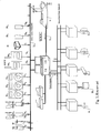
- a control system for a ship with inputs from instruments that give measurements, and with outputs to actuators, like propelling devices, control surfaces and other control devices that are to be given control signals, is shown in Fig. 1 and in Fig. 3 .
- This type of control system can receive measurements in the form of sensor signals from a number of sources:
- the control system is to give control signals to actuators like propulsors, control surfaces and other control devices.
- the propulsors may be ordinary propellers, tunnel thrusters, azimuth thrusters and water jets, and for some vessels also a mooring system that is designed to pull the vessel to the right position.
- Control surfaces include rudders for steering and active foils for damping or counteracting of wave motion.
- Control signals can also be given to other control devices like ballast pumps and associated valves to correct the roll angle or the pitch angle.
- the control system may also receive measurements of the heave motion from a heave accelerometer, and output a control signal to an active heave compensation system for a riser, a drill string, cranes, etc. where mechanical equipment can be connected to the seafloor and where it can be important to compensate for the motion of the vessel, in particular heave.
- a normal use of control systems for petroleum activity at sea is for dynamic positioning of the vessel, that is, that the vessel uses actuators like azimuth thrusters to maintain desired position during drilling or during production of petroleum.
- a vessel that is moored and may rotate about a rotating turret with mooring lines to the seafloor can also have a control system that gives a varying control signal to propellers or thrusters to assist in keeping the desired position when the vessel is rotated because the direction of the weather or current changes, so that the thrusters contribute with forces to compensate for changes in the tension of mooring lines when the forces turn.
- the control system can give control signals to increase or decrease tension in the mooring lines of the same reason.
- a ship inspector can visit a vessel and make an on-board test of the control system.
- the on-board test may be conducted by disconnecting or connecting sensor systems and monitoring the response of the system in different failure situations.
- Such kind of tests will normally not be performed.
- Such interconnecting and testing could be conducted on the vessel, but a disadvantage of visiting the vessel to be tested is often related to a long way of travel for the ship inspector, that the ship inspector must bring equipment for interconnection to the control system inputs for measurements, and equipment for interconnection to the control system outputs for response in the form of control signals that are normally sent to the actuators of the vessel, and in addition a data library that at least has to include the configuration of the actual vessel to be tested.
- the travel time from one vessel that is to be tested and certified to a next vessel can make it difficult for the inspector to perform inspections at a sufficiently high rate, so that the next vessel will have to wait, with the economic disadvantages caused by the waiting, if the vessel cannot be taken into use without being tested and properly certified. It may also cause a concealed physical danger to use a vessel where lack of testing of the control system does not reveal possible errors.
- FAT factory acceptance test
- the manufacturer feeds simulated sensor data to the control system and monitors which control signals the control system gives as a response to the simulated data.
- This type of FAT can only reveal errors where measurements from sources that the manufacturer has foreseen to exist, and where the control signals are only related equipment that the manufacturer have foreseen.
- the control system will not be tested in the connection where the control system is installed and connected for use on the vessel.
- the vessel In dynamic positioning of a vessel (4) that is held in desired position of propellers, rudders or thrusters of the tunnel or azimuth type, it may be essential for the operation that the vessel keeps its position within a very small radius from the desired position, e.g. a radius of 2 m.
- Several events may be undesired.
- the vessel may experience loss of motor power for one or more propellers or rudders, and have to increase the motor power on the remaining propellers and/or thrusters and perhaps rotate the still functioning remaining rudders or thrusters.
- One may also experience serious error situations in which the control system loses some of the signals from the connected sensors so that an undesired incident may occur.
- the inventors have knowledge of an instance in which a vessel, in the actual case a drilling platform, was to be located at a fixed position in the open sea and was drilling to make a petroleum well in the seafloor.
- the drilling platform was to maintain the desired fixed position by means of so-called dynamic positioning or "DP", that is, the control system was arranged to keep the vessel in the desired position by means of position measurements and motor power, without the use of mooring lines to the seafloor.
- the drilling platform was equipped with a double set of DGPS receivers that calculate the geographic position of the vessel based on radio signals received from a number of navigation satellites.
- the drilling platform was equipped with a double set of hydroacoustic position sensors that measured the position of the vessel with respect to transponders at fixed points on the seafloor.
- the vessel having riser connection to a wellhead and drill string connection to the drilling hole and actively drilling, an event took place so that the DGPS receivers showed a sudden change in position of about 75 meters, although no such change in position actually had occurred.
- Such an error may be called a "step change" error.
- the hydroacoustic sensors continued to indicate a stable position at the desired position over the drill hole.
- the control system continued to control propellers and rudders so that the drilling platform without interruption was held at the correct dynamic position on basis of the hydroacoustic sensor measurement signals. However, it turned out that after 5 minutes the drilling platform suddenly started to move off towards the desired position according to the then erroneous DGPS signals.
- the loss of the DGPS signal may have been ignored by the control system because of quality conditions in the software of the control system requiring that such a calculated position must have been stable during the preceding 5 minutes to be considered to be real. In this way, the designer of the control system may have believed to prevented undesired sudden changes in position due to erroneous signals.
- the new and changed, but nevertheless stable, false position calculated from the DGPS receivers may after 5 minutes have been regarded as stable and was thus considered to be reliable according to the logical program of the control system, and may have been given a higher priority than the measurements provided by the hydroacoustic transponders.
- Marine operations related to oil and gas exploration and production are done by vessels with cranes for installation and intervention on modules on the seafloor.
- This type of cranes has control systems that compensates for the vertical motion of the vessel.
- the mode of operation and the function of the crane in safety-critical situations will to a large extent depend on the detailed design of the software of the control system, which will vary from one crane to another.
- Procedures have been established for the testing of the mechanical design of such cranes. In contrast to this there are no established systems or methods for the testing of the software of the crane control systems.
- the reason for this is that the response of the crane will depend on the sea state and the motion of the vessel in addition to the mechanical design and the control system of the crane.
- a required detailed testing of a crane system on a vessel should therefore involve both the dynamics of the vessel including the relevant control systems of the vessel, and in addition, the dynamics of the crane including the control system of the crane.
- sensors for a control system When sensors for a control system are replaced or modified, there is a need for adjustment of alarm limits, for limits for acceptable variations in the sensor signals. It is customary for a control system to have redundant sensor systems so that several sensors may be used to measure the same physical quantity.
- the position of a vessel can be measured by inertial sensors, two or more GPS-receivers and two hydroacoustic sensor systems. From these measurement data the position of the vessel is determined by means of an algorithm in the control system. This algorithm will depend on the properties of the various sensors with respect to accuracy and properties like long term stability versus accuracy under rapid position variations. Replacement or modification of a sensor introduces the need for testing of the total sensor system to investigate whether the resulting new combination of sensors gives acceptable position measurements for use in a control system.
- a control system may give a significantly different response for the vessel.
- the reason for this is that a new or modified actuator may give a different control action to the vessel than what was assumed during the development of the control system.
- An example of this is in the use of thrusters for dynamic positioning, where the relation between the shaft speed of the thruster and the thrust must be known when the control system is tuned. If a thruster is changed, then the relation between the shaft speed of the thruster and the thrust may be changed, and it will be necessary to test the vessel with the control system to investigate if the system still performs according to specifications.
- the US-Patent 6 298 318 "Real-time IMU signal emulation method for test of guidance navigation and control systems" describes an emulation method for testing of a plane by emulating the motion using a so-called 6 degrees-of-freedom (6 DOF) flight simulator and where signals from a so-called inertial navigation module to a "guidance, navigation and control" system on board the aircraft are generated by simulation.
- 6 DOF 6 degrees-of-freedom
- This US patent does not discuss problems related to dynamic positioning of a vessel in drilling operations or some other form of stationary operation, it does not mention the use of cranes, navigation of connected underwater equipment, integration of hydroacoustic positioning equipment, problems related to ballasting, and does not consider ocean waves.
- the US-patent 5023791 "Automated test apparatus for aircraft flight controls" describes an automated test apparatus for the testing of flight control systems of an aircraft as part of an integrated system for testing a plurality of flight control systems.
- the automated test apparatus includes a system controller having memory for storing programmed instructions that control operation of the automated test apparatus, and for storing resulting flight controls system test data.
- the automated test apparatus includes a keyboard, a touch-screen, and a tape drive for entering programmed instructions and other information into the automated test apparatus, and for outputting test data from the system controller.
- Instruments included in the automated test apparatus and controlled by the system controller generate test signals that are input to the aircraft's flight controls system, and monitor resulting test data signals that are produced by the flight controls system.
- the automated test apparatus is connected by an interface cable to an onboard central maintenance computer included in the aircraft.
- the central maintenance computer includes a non-volatile memory that is programmed to run onboard tests of the flight controls system, and is controlled by the system controller during testing in accordance with the programmed instructions to run the onboard tests.
- US-patent 5260874 Aircraft flight emulation test system
- the aircraft test system includes a number of instruments for generating the number of processor-controllable instruments for generating stimuli received by an aircraft when in flight.
- the system also includes a number of instruments that monitor the response of the various aircraft components to the stimuli to which the aircraft is exposed.
- a processor in response to the output signal from the aircraft components directs the stimuli generating instruments to produce stimuli that emulate those received by the aircraft as it moves through the air.
- the system thus generates an initial set of stimuli similar to what an aircraft would be exposed to when in flight; monitors the response of the aircraft to the stimuli to which it is exposed; and, in response generates an updated set of stimuli to the aircraft.
- the system also records the response of the output responses of aircraft components so that they could be monitored by personnel charged with insuring that the aircraft is functioning properly.
- the system can also be used to train flight crews since it can be used to place the aircraft "in the loop" during a flight emulation.
- US-patent 6505574 "A vertical motion compensation for a crane's load” describes a method and a system for reducing sea state induced vertical motion of a shipboard crane's load using winch encoders, boom angle sensor, turning angle sensor and motion sensor that all feed measurements into a central processor that controls the crane on basis of the measurements and the commands from a crane operator.
- a solution to some of the problems described above is a method for verifying a control system of a vessel, in which said control system in its operative state is arranged for receiving sensor signals from sensors and command signals from one or more command input devices, and in which said control system as a response to said measurements and command signals, provides control signals to said vessel's actuators in order to maintain a desired position, velocity, course or other state of said vessel; in which the method comprises the following novel steps:
- the invention includes a system for and a method for testing of a control system (2) on a vessel (4), e.g. a ship, a drilling platform, a petroleum production platform, in real time over a communication channel (6), as shown in an overview in Fig. 4a and in more detail in Fig. 4b and 4c .
- the control system (2) may include control and monitoring of the vessel (4). Testing of the control system (2) may include the simulation of normal states and extreme states and normal changes to such normal and extreme states for the vessel (4), for example ordinary movement in a simulated calm sea state (H1).
- the system according to the invention is arranged for the testing a control system (2) in a vessel (4), of which the control system (2) is arranged to control and monitor the vessel (4).
- the system comprises the following features:
- the control signals (13) include signals (13a, 13b, 13c) in the form of shaft speed (13a, 13b) for one or more propellers (16) or thrusters (17), and rotation angles (13c) for rudders (18) or thruster (17) and possibly other actuators like ballast pumps, or cranes.
- the sensors (8) may comprise one ore more devices selected from numerous different devices, of which some are mentioned below:
- the system is provided with a switch (15a) arranged to disconnect one or more sensor signals (7) from the signal line (12) to the control system (2).
- the system according to the invention can be equipped with a second switch (15b) arranged to disconnect one or more of the command signals (10) from the signal line (11) to the control system (2), and also equipped with a third switch (15c) arranged to disconnect one or more of the control signals (13) from the signal line (14) from the control system.
- the switches (15) can be used to fully or partially isolate the control system (2) from signals to and from the rest of the vessel.
- the control system (2) should of course still be connected to the regular electrical power supply on board.
- the system implies in the normal manner that the dynamic parameters (5) of the vessel may enter into the algorithm (31) of the control system (2) for the computation of the control signals (13) to the actuators (3).
- the system may be arranged so that the remote test laboratory (40) is equipped with a simulator (30R) with an algorithm (32) arranged to simulate the state of a vessel on basis of an initial state represented by completely or partially simulated measurements (7, 7') and control signals (13, 13') from the control system (2), but an equivalent simulator (30L) may be arranged locally on board the ship to prevent communication delay problems.
- a simulator (30R) with an algorithm (32) arranged to simulate the state of a vessel on basis of an initial state represented by completely or partially simulated measurements (7, 7') and control signals (13, 13') from the control system (2), but an equivalent simulator (30L) may be arranged locally on board the ship to prevent communication delay problems.
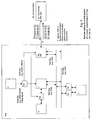
- the communication line (6) may be arranged for sending of one or more simulated sensor signals (7') from the remote test laboratory (40) which is further arranged to be connected to and disconnected from a first real-time interface (6a), on the remote test laboratory (40). Similarly, the communication line (6) is arranged to be connected to, and disconnected from, a second real-time interface (6b) on the vessel (4). The second real-time interface is arranged for being connected through the switch (15a) to the signal line (11) to the control system (2).
- the communication interface (6b) is connected via a local vessel simulator computer (30L) to said switch (15a), as illustrated in Fig. 9 , and also in Fig. 4c .
- the test system may comprise the use of a remotely arranged simulator computer (30R) in said remote test laboratory (40) for transmitting said simulated sensor signals (7') and said simulated command signals (9') via said communication line (6) to said local simulator (30L) on said vessel, and receiving said control signals (13') from said local simulator computer (30L) via said communication line (6).
- a remotely arranged simulator computer (30R) in said remote test laboratory (40) for transmitting said simulated sensor signals (7') and said simulated command signals (9') via said communication line (6) to said local simulator (30L) on said vessel, and receiving said control signals (13') from said local simulator computer (30L) via said communication line (6).
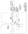
- the test system may also comprise the use of a remotely arranged test manager (33) in said remote test laboratory (40) for transmitting an initial value of said simulated state (50'), a time sequence of said simulated command signals (9'), and simulated values for sea state, current, wind speed and wind direction via said communication line (6) to said local simulator (30L) on said vessel, and receiving said control signals (13') from said local simulator computer (30L) via said communication line (6), where said local simulator (30L) is connected to said control system (2) so that said control system acquires said simulated sensor signals (9') and said simulated command signals (9') from said local simulator (30L) and outputs said control signals (13') to the local simulator (30L).
- a remotely arranged test manager (33) in said remote test laboratory (40) for transmitting an initial value of said simulated state (50'), a time sequence of said simulated command signals (9'), and simulated values for sea state, current, wind speed and wind direction via said communication line (6) to said local simulator (30L) on said vessel, and receiving said
- a simulated command input device (10') may be arranged remotely for sending of simulated command signals (9') from the remote test laboratory (40) over the real-time interface (6a), and over the communication line (6) and over the real-time interface (6b) to the control system (2).
- a simulated or test command input device (10', 43) may be arranged locally on board the ship for generating and sending of simulated command signals (9') directly to the control system (2).
- simulated command signals (9') may be included in a test series (T0) comprising simulated sensor signals (7') and simulated command signals (9') as explained below.
- a local test signal source (41 L) may be arranged at or near the vessel (4) to be tested, for providing said artificial measurements (7') or artificial commands (9') to the control system (2).
- a control signal logger (42) is used for recording a response (S0) from the control system (2) upon the given artificial measurement signal sequence (T0).
- the same control signal logger (42) may also be used for recording a later response (S1, S2, S3, ...) to said given sequence (T0), or, of course, other measurement sequences (T1, T2, T3, ..) being real or artificial.
- a memory (44) may be connected to the test signal source (41 R/41 L) for storing the test sequence (T0) used for establishing said control system signature response (SO), or/and for storing later test sequences (T1, T2, T3, ..)
- the system may be arranged so that all of or parts of the algorithm (31) in the control system (2) can be modified, calibrated, or replaced, locally or over a communication line (6) from a remote test laboratory.
- the ship and / or the test laboratory includes a data logger (15) for logging of the response (13', 19') from the control system (2) to the measurements (7, 7').
- the system described above may be arranged to be used in a method for testing of a control system (2) in a vessel (4).
- the control system (2) includes control and monitoring of the vessel (4) with control signals (13) to one or more actuators (3).
- the method for testing the control system may comprise the following steps:
- the method will then include simulation in a remote simulator (30R) in the test laboratory (40) or in a local simulator (30L) by means of an algorithm (32) of a new dynamic state of a vessel model (4') on basis of the control signals (13').
- a test on the control system (2) can be performed from the remote test laboratory (40) on a vessel independently of where the vessel is placed in the world.
- the simulation algorithm must take into account the time delay caused by the use of the communication line (6).
- the remote computer (30R) may transmit the data (7', 9') to be used for a simulation via the communication line (6) to the local simulation computer (30L) at the vessel, as shown in Fig.
- the remote computer (30R) commands the local computer (30L) to start disconnecting the real sensor and command signals (7, 9) and replace these signals by the artificial sensor and command signals (7', 9') to the control system (2), and to similarly disconnect real output control signals (13) with the test output (13') and store these locally and using the test output (13') online in a simulating algorithm (32) to simulate the dynamic behaviour of the vessel model (4') as described above, as well as transmitting the test output (13') back to the remotely arranged computer (30R) at the remote test laboratory (40).
- the test output (13') need not be transmitted in an online manner to the remote test laboratory, but may be returned to the remote test laboratory in one or more batches during or after the test has been conducted.
- the test output (13') may then be recorded and analysed at the remote test laboratory (40).
- the remote test laboratory (40) that is involved in the testing of the control system can be located on land, and the vessel (4a, 4b, 4c, ...) that is tested is a long distance from the test laboratory, typically between 1 and 20000 km, and where the vessel (4a, 4b, 4c, ..) that is tested may be situated in a nearby harbour, in a distant harbour, in a dock or in a yard, at anchor, or in the open sea.
- the communication line between the vessel and the remote laboratory is disconnected, and the regular sensor signals and the regular command signals to the control system are reconnected, and the control signals from the control system are reconnected to the actuators, for normal operation of the control system in the vessel.
- the sensor signals (7) includes one or more of the following sensor parameter from sensor (8):
- control signals (13) include signals (13a, 13b, 13c) in the form of shaft speed of one or more propellers (16) or thrusters (17), and angles for rudders (13c) or thrusters (17) and possibly other control devices to achieve one or more of desired position (9a), course (9b), velocity (9c).
- the method can be used to calculate control signals to one or more propellers (16a, 16b, 16c, ..), and control devices (18) may include one or more rudders (18a, 18b), and it may include one or more thrusters (17).
- the command input device (10) will include one or more of the following items: a position specification device (10a), a steering wheel (10b), a velocity specification device (10c), or a device for specification of desired inclination angle, pitch angle, heave compensation, etc. (10x) that give a command signal (9) of one or more of desired position (9a), desired course (9b), and desired velocity (9c) or another desired state (9x), e.g. desired roll angle, desired pitch angle, desired heave compensation, etc.
- the method may include that the remote test laboratory (40) is used to verify that the control system (2) on basis of the simulated sensor signals (7') in the test, and possibly remaining real sensor signals (7), the simulated command signals (9') and possibly remaining real command signals (9) gives control signals (13, 13') that will lead to an acceptable response (S) and resulting in the control system (2) being certified on basis of the test.
- the remote test laboratory (40) is used to verify that the control system (2) on basis of the simulated sensor signals (7') in the test, and possibly remaining real sensor signals (7), the simulated command signals (9') and possibly remaining real command signals (9) gives control signals (13, 13') that will lead to an acceptable response (S) and resulting in the control system (2) being certified on basis of the test.
- the dynamic parameters (5) of the vessel may involve the mass (m), the axial moments of inertia, the mass distribution of the vessel, and the hull parameters that describe the geometry of the hull, as explained below.
- Disconnection of the sensor signals (7) from the sensors (8) to the control system (2) can be done by means of a switch (15a) on the signal line (12).
- the disconnection of command signals (9) from the command input devices (10) to the control system (2) can be done by means of a switch (15b) on the signal line (11).
- Failure situations could be tested by disconnection of one or more of selected sensor signals (7) or command signals (9) at the time to simulate breakdown of components, and where the response of the control system (2) in the form of control signals (13, 13') and status signals (19, 19') are logged in a logger (15), either locally or in the test laboratory (40).
- a logger either locally or in the test laboratory (40).
- testing would be laborious and difficult to repeat at a later occasion for verification.
- Failure situations can also be tested by changing measurements or by generating disturbances in selected sensor signals (7'), or by generating external disturbances like weather, wind, electrical noise, atmospheric noise or acoustic noise to the measurements (7').
- Such disturbances may be sent from the remote test laboratory (40) to the control system (2) in the vessel (4), and where the response of the control system (2) in the form of control signals (13, 13') and status signals (19, 19') are logged on a logger (15) in the test laboratory (40).
- new software for the control system (2) in the vessel (4) can be transmitted from the test laboratory (40) over the communication line (6).
- test laboratory (40) on basis of the test of the control system (2) and the test results can approve the control system (2)
- the test laboratory (40) can certify the control system (2) for use in regular operation of the vessel (4).
- One of the advantages of the proposed remote testing according to the invention is that one will have a much larger flexibility in the testing of the software and the control system (2) in its entirety under simulated failure situations and under a simulated extensive spectrum of weather loads than what would be the case under conventional testing and certification.
- the proposed invention it is possible to test and certify far more vessels than previously, with a lower number of operators.
- the quality of the testing will be improved as the automatic test execution improves the repeatability of the tests.
- the present invention can be used to test if a control system as mentioned above will indeed function in a safe and reliable way.
- a control system (2) in a drilling vessel (4) as illustrated in Fig. 7 . Drilling is terminated before the test so that potential errors in position under the test with simulated dynamically positioned drilling will not have negative consequences.
- the drilling vessel (4) includes a control system (2) that corresponds to what is illustrated in Fig. 4a, b and c , and is in the same way connected through a real-time interface (6b) and a communication line (6) and through a real-time interface (6a) to a remote test laboratory (4) as shown in the drawings.
- the control system (2) comprises control and monitoring of the drilling vessel (4) with propulsion devices (16) like propeller (16a, 16b, 16c, ..) or thrusters (17), and control devices (18) like rudders (18), thrusters (17) in the form of tunnel thrusters and azimuth thrusters.
- the thrusters (17) can act both as propulsion devices (16) and control devices (18).
- Under the simulated drilling it is desirable that the drilling vessel (4) is at a stationary position (9a) with a smallest possible position deviation, and with a course (7b) and velocity (7c) that only compensate for the weather in the form of its influence on wind, waves and current.
- the method for dynamic positioning in agreement with known methods may comprise the following steps that can be executed sequentially:
- the control system (2) may then be regarded as a "black box” (2) where a change is simulated in at least one of the sensor signals (7) to the "black box” (2), and where the "black box” (2) responds with a control signal (13).
- a control signal 13
- the control system (2) would suddenly attempt to control the propellers, thrusters and rudders of the vessel (4) in order to move the vessel to a new position that the control system would suddenly regard as correct because it had been given as stable and wrong for 5 minutes.
- the motion of a vessel (4) is described in terms of the velocity of the ship in surge, sway and yaw, by the position of the centre of mass, and by angles in roll, pitch and yaw, see Fig. 5 .
- the set of variables (velocities, positions, angles of rotation, etc.) that uniquely describe the motion of the vessel is said to be the state (50) of the vessel.
- a vessel will be exposed to forces and moments that influence the motion of the vessel.
- the following procedure can be used to compute the motion of a vessel (4, 4') as given by the state (50, 50') over a time interval from u 0 to u N :
- the motion of the vessel is given in terms of the state (50') at the initial time instant u 0 , and the fo rces and moments are calculated at this time instant.
- the acceleration and angular accelerations of the vessel at time u 0 can then be computed from the equations of motion for the vessel (4, 4').
- the time step h will typically be in the range 0.1 - 1 s.
- the motion (50, 50') of the vessel (4, 4') at time u 1 is computed, the forces and moments at time u 1 can be computed, and the acceleration and angular acceleration at u 1 are found from the equations of motion.
- the waves that act on a vessel are described as a sum of wave components where one wave compoment is a sinusoidal long-crested wave with a given frequency, amplitude and direction.
- one wave compoment is a sinusoidal long-crested wave with a given frequency, amplitude and direction.
- the prevalent distribution of amplitude and frequency of the wave components will be given by known wave spectra like the JONSWAP or ITTC spectra, where the intensity of the wave spectrum is parameterised in terms of the significant wave height.
- the resulting forces and moments acting on the vessel will be a function of the amplitude, frequency and direction of the waves, and of the velocity and course of the vessel.
- Forces and moments from wind will be given by wind speed, wind direction, vessel velocity and the projected area of the ship above the sea surface as a function of the vessel course relative to the wind direction.
- Forces and moments from current will be given by the current speed, current direction, the projected area of the hull under the sea surface, and by the vessel velocity and course relative to
- DP the vessel (4) is controlled in three degrees of freedom (DOF).
- DOF degrees of freedom
- the desired position in x and y and in course are given as inputs from an operator using keyboard, roller ball, mouse or joystick on a control panel (10).
- a control system (2) is used to compute the required actuator forces in the surge and sway directions, and the actuator moment about the yaw axis so that the vessel achieves the desired position and course.
- the control system (2) also includes actuator allocation, which involves the computation of propeller forces, rudder forces and thruster forces corresponding to the commanded actuator forces and moments.
- the control system (2) is implemented through the running of an algorithm (31) on a computer on board the vessel (4).
- This algorithm (31) compares the desired position (9a) and course (9b) with the measured position and course (7a, 7b), and of basis of this the algorithm computes the required actuator forces and moments using control theory and found in textbooks.
- the algorithm includes an allocation module where propeller forces, rudder forces and thruster forces are computed.
- the position and course are measured by DGPS sensors, gyrocompasses, hydro-acoustic sensor systems where transponders are laced on the sea floor, and taut-wires where the inclination of a taut wire fixed on the sea-floor is measured.
- Another example is the sudden loss of an acceleration measurement signal in heave compensation, in which case the system cannot give an accurate compensation of the heave motion of the vessel and potentially difficult situations can occur if the load is in the wave zone or close to the sea floor during installation of the load at a specific place at the seafloor, or in heave compensation of a drilling riser with a rotating drilling string arranged between the vessel and a well through the seafloor.
- a proposed approach according to an embodiment of the invention is to test a control system (2) for a given vessel by running the control system with inputs in the form of simulated sensor signals (7a', 7b', ..) and simulated command input signals (9a', 9b' ..), and in which the outputs of the control system (2) in the form of control signals (13a, 13b, ..) are used as control signals to the simulated vessel model (30).
- a test scenario for the control system is generated in the form of a sequence of test cases that are to be tested for the given vessel.
- Each test case is given by a specified sea state, specified wind speed (7d') and wind direction (7d'), specified water current speed (7k) and current direction (7l), and a predetermined sequence of command input signals (9a', 9b', 9c', ..).
- each test case may involve a sequence of predetermined errors that are added to the simulated sensor signals (7a', 7b', 7c', ..), e.g. an additional step change of 75 m in one or more DGPS receivers (see Fig.
- the input sensor signals, the input command signals and the resulting control signals are logged, and based on analysis of the logged test data it is decided if the control system performed satisfactorily in the test, and on basis of this the control system may be approved or not approved, and possibly certified on basis of this.
- a signature S0 is established according to a preferred embodiment of the invention by generating a preferably predetermined sequence T0 of one or more artificial sensor signals (7a', 7b', ..) and input command signals (9a', 9b', ...) for use as inputs to the control system (2) instead of the real sensor signals (7a, 7b, 7c, ..) and real input command signals (9a, 9b, 9c, ..), and recording the resulting output from the control system (2) as a signature (S0) in the form of control signals (13a, 13b, 13c, ..), that in this case preferably may not be sent to the actuators (17, 18, 19).
- this original signature (S0) is then a complete time section history of the control signals.
- control system (2) To test whether a control system (2) has been modified, the same input sequence T0 is input to the control system (2) at some later times (t1, t2, t3, ...), and resulting output in the form of control signals (13a, 13b, 13c, ..) are recorded as new system responses or "signatures" (S1, S2, S3, ..). For determining whether said control system (2) has changed or been modified, a comparison must be made between the original signature (S0) and the new signatures (S1, S2, S3, ..).
- a preferred embodiment of the invention comprises a method for verifying a control system (2) of a vessel (4).
- the control system (2) in its operative state is arranged for receiving sensor signals (7) from sensors (8) and command signals (9) from one or more command input devices (10).
- the control system (2) as a response to said measurements (7) and command signals (9), provides control signals (13) to the actuators (3) of said vessel in order to maintain a desired position, velocity, course or other state of said vessel (4).
- the method is characterised by the following steps:
- the method has the purpose of, at a later time (t1, t2, t3, ..), using the same given test seq uence (T0) input to said control system (2), and recording a later response (S1, S2, S3, ..) from said control system (2), and determining whether said later response (S1, S2, S3, ..) is generally similar to said signature response (S0) to verify that said control system (2) is unchanged, or whether said later response (S1, S2, S3, ..) is significantly different from said signature response (S0) to indicate that said control system (2) has been changed.
- the later acquired system response S1 is, according to the invention, compared to the original system response or "signature" S0. If there is little difference between S0 and S1, then the systems is considered to be unchanged, and there is no need for a new test for renewed approval or certification. If there is a significant difference between S0 and S1, then it is concluded that the control system has been modified, the approval or certification is no longer valid, and a new approval / certification test should be conducted. To determine what is a significant difference one must consider several limitations realistically: The signatures S0 and S1, and later system responses, may contain some noise and high frequency components, as will the test sequence T0, so acquired system responses will never be exactly equal. Below follows an outline of a method to compute the difference.
- the following computation method may in a preferred embodiment of the invention be used to determine the difference between said control system's original response (S0) recorded at time t 0 , and a later response (S1) recorded at t 1 , which may be on the order of week, months or years after to.
- the control signals are recorded at time instants u 1 , u 2 , ..u n ..., u N , with intervals in the order of seconds during the test initiated at time to to establish the original response S0, or during the test initiated at time t 1 to establish the response S1.
- control system For each time instant u 1 , u 2 , ..u n ..., u N , the control system will output several control signal comprising control channel signals like (13a, 13b, 13c, ....13K), which we may call a multidimensional signal.
- the multidimensional values of the sequence S0 at time u n is denoted S ⁇ 0 u n , 1 u n , 2 u n , 3 u n , 4 .. u n , m .. u n , K , in which the first subscript n in u n is one time instant, and the second subscript 1, 2, 3, 4, ...m, ..
- the multidimensional values of S1 at the time instant u n is S ⁇ 1 u n , 1 u n , 2 u n , 3 u n , 4 .. u n , m .. u n , K .
- the sequences S0 and S1 are low pass filtered.
- the filtered version of S0 is called SF0 , at a time u n denoted S ⁇ 0 u n , 1 u n , 2 u n , 3 u n , 4 .. u n , m .. u n , K
- the filtered version of S1 is called SF1 at the time u n denoted S ⁇ F ⁇ 1 u n , 1 u n , 2 u n , 3 u n , 4 .. u n , m .. u n , K .
- the difference between S0 and S1 is then characterized in terms of RMS value for the difference between SF0 and SF1.
- the RMS can be viewed as a weighted mean value of the difference between the two sequences SF0 and SF1. If the RMS(S0, S1) is larger than some threshold value, e.g. 0.01 or 1 %, then there may be a significant probability that the control system has been modified or altered, and a new test should be conducted for approval or certification. Else, if RMS(S0, S1) is less than the threshold value, then the system is considered to be unchanged, and the approval and / or certification may be considered to be valid. To further improve the quality of the comparison, the alarm and event lists associated with S0 and S1 may be analysed qualitatively.
- some threshold value e.g. 0.01 or 1 %
- the method described above for the generation of a signature can be used to generate a signature for an entire control system, or expanded to a set of integrated control systems.
- An alternative approach is to generate a set of signatures where each signature is related to the performance of the control system in relation to a specific set of sen sors or to a specific function of the control system.
- the procedure is then to generate a predetermined sequence TG10 of artificial sensor signals (7a', 7b', 7c' ..) from sensor group 1 of one or more sensors and recording the resulting output as a signature SG10 in the form of control signals (13a, 13b, 13c, ..), where the signature SG10 related to sensor group G1.
- a set of input sequences TC10, TC20, TC30, .... of artificial command input signals (9a', 9b', ...) are generated to test the system with respect to different combinations C1, C2, C3 ... of command input signals.
- the resulting outputs are recorded as the signatures SC10, SC20, SC30, .... in the form of control signals (13a, 13b, 13c, ..), where the signatures SC10, SC20, SC30, .... are related to the combinations C1, C2, C3 ... of command input signals.
- the control system can be tested at a later times (t1, t2, t3, ).
- n there will be input sequences TG1n, TG2n, TG3n, .... and TC1n, TC2n, TC3n, .... leading to responses SG1n, SG2n, SG3n,.... and SC1n, SC2n, SC3n, ...
Landscapes
- Engineering & Computer Science (AREA)
- Physics & Mathematics (AREA)
- General Physics & Mathematics (AREA)
- Automation & Control Theory (AREA)
- Chemical & Material Sciences (AREA)
- Combustion & Propulsion (AREA)
- Mechanical Engineering (AREA)
- Ocean & Marine Engineering (AREA)
- Aviation & Aerospace Engineering (AREA)
- Radar, Positioning & Navigation (AREA)
- Remote Sensing (AREA)
- Testing Or Calibration Of Command Recording Devices (AREA)
- Testing And Monitoring For Control Systems (AREA)
- Examining Or Testing Airtightness (AREA)
- Steering-Linkage Mechanisms And Four-Wheel Steering (AREA)
- Control Of Vehicle Engines Or Engines For Specific Uses (AREA)
- Navigation (AREA)
- Cyclones (AREA)
Claims (38)
- Méthode qui consiste à vérifier un système de régulation (2) à bord d'un bâtiment de surface de la marine (4), dans lequel le système de régulation (2) reçoit, lorsqu'il est opérationnel, des signaux de mesure (7) rovenant de plusieurs capteurs (8) ainsi que des signaux de commande (9) provenant d'un ou de plusieurs unités d'introduction des commandes (10), et dans lequel le système de régulation (2), réagissant aux signaux de mesure (7) et aux signaux de commande (9), transmet des signaux de régulation (13) aux organes de commande (3) du navire afin d'en maintenir la position, la vitesse, le cap ou toute autre variable requise pour le navire (4);
la méthode étant caractérisée par les étapes suivantes :* au cours d'un premier moment (t0), cette méthode sert à déconnecter la réception d'un ou de plusieurs signaux réels de capteurs (7a, 7b, 7c, ...) se rendant au système de régulation (2), et elle remplace un ou plusieurs de ces signaux réels de capteurs par une première séquence de test (TO) comprenant une ou plusieurs mesures artificielles (7a', 7b', 7c', ...) qui proviennent d'une source de signaux de test (41) et qui se rendent au système de régulation (2) ;* sur la base de signaux réels et / ou artificiels de capteurs (7, 7'), elle permet au système de régulation (2) de générer des signaux de régulation (13') qui seront enregistrés, en tant que signaux de régulation (13) du système de régulation (2) en tant que réponse (S0) à la première séquence de test (TO) pour le premier moment (t0), sur un enregistreur de signaux de régulation (42);• elle permet de ranger en mémoire la réponse (S0) du système de régulation (2) à la première séquence de test (TO) pour le premier moment (t0) en tant que réponse "signature" (S0) du système de régulation (2) ;cette méthode ayant pour but, à un moment ultérieur (t1, t2, t3, ...), d'employer la même séquence de test (TO) introduite dans le système de régulation (2) et d'enregistrer une réponse ultérieure (S1, S2, S3, ...) provenant du système de régulation (2), et aussi de déterminer si cette réponse ultérieure (S1, S2, S3,...) est généralement similaire à la réponse signature (S0) afin de vérifier si le système de régulation (2) reste inchangé, ou bien si cette réponse ultérieure (S1, S2, S3,...) est sensiblement différente de la réponse signature (S0), ce qui indiquerait que le système de régulation (2) a fait l'objet d'une modification. - Méthode selon la revendication 1, caractérisée en ce que le remplacement d'un ou de plusieurs signaux réels de capteurs (7a, 7b, 7c, ...) par des signaux artificiels de capteurs (7a', 7b', 7c', ...) comporte une ou plusieurs conditions pour les signaux:* la simple absence ou présence d'un ou de plusieurs signaux artificiels de capteurs (7a', 7b', 7c', ...) ;• le changement indiciel d'un ou de plusieurs signaux artificiels de capteurs (7a', 7b', 7c', ...) dans une plage réaliste;• une dérive ou une variation lente d'un ou de plusieurs signaux artificiels de capteurs (7a', 7b', 7c', ...) dans une plage réaliste du signal réel correspondant (7a, 7b, 7c, ...) ;• du bruit « blanc »; ou• la superposition du bruit sur des signaux réels de mesure (7) ou sur des signaux artificiels de mesure (7').
- Méthode selon la revendication 1, caractérisée en ce que la séquence de test (TO) comporte un ou plusieurs signaux de mesure réels enregistrés (7a ou 7a', 7b ou 7b', 7c ou 7c', 7d ou 7d', ...).
- Méthode selon la revendication 1, caractérisée en ce que la séquence de test (TO) est rangée dans une mémoire (44) qui est connectée à la source de signaux de test (41).
- Méthode selon la revendication 1, caractérisée en ce que la séquence de signaux de capteurs (7') comporte des signaux de capteurs prédéterminés (7').
- Méthode selon la revendication 1, caractérisée en ce que cette méthode est employée pour tester un système de régulation (2) servant à assurer le positionnement dynamique du navire (4) qui maintiendra alors une certaine position requise (7a) dans un rayon d'action donné à partir de la position (7a) du navire.
- Méthode selon la revendication 1, caractérisée en ce que cette méthode est employée pour tester un système de régulation (2) pour un navire (4) qui navigue en mer, comme par exemple un navire à passagers, un ferry-boat, un cargo, un navire-citerne, ou un autre navire similaire naviguant entre différents ports de destination ou bien entre un point de cheminement et un autre.
- Méthode selon la revendication 1, qui consiste par ailleurs à transmettre au système de régulation (2) sur une ligne de communication la séquence de signaux de test (TO) comportant les mesures artificielles (7a', 7b', 7c', 7d',...) (6) en provenance d'un laboratoire de test à distance (40).
- Méthode selon la revendication 1 ou 8, qui consiste par ailleurs à transmettre la séquence de signaux de régulation (S0, S1, S2) à partir du système de régulation (2) sur une ligne de communication (6) en direction d'un laboratoire de test (40).
- Méthode selon la revendication 8 ou 9, qui consiste par ailleurs à utiliser un ordinateur de simulation (30R) situé dans le laboratoire de test à distance (40), et servant à transmettre les signaux simulés de capteurs (7') et les signaux de commande simulés (9') sur la ligne de communication (6) en direction de l'ordinateur de simulation local (30L) à bord du navire, et servant aussi à recevoir sur cette ligne de communication (6) les signaux de régulation (13') provenant de l'ordinateur de simulation local (30L).
- Méthode selon la revendication 8 ou 9, caractérisée en ce qu'un gestionnaire de test (33) est prévu dans le laboratoire de test à distance (40), et il sert à transmettre une valeur initiale de l'état simulé (50'), une séquence temporelle des signaux de commande simulés (9'), ainsi que des valeurs simulées pour l'état de la mer, le courant, la vitesse du vent et la direction du vent sur la ligne de communication (6) en direction du simulateur local (30L) à bord du navire, et aussi à recevoir les signaux de régulation (13') provenant de l'ordinateur de simulation local (30L) sur cette ligne de communication (6), l'ordinateur de simulation local (30L) étant connecté au système de régulation (2) de telle manière que le système de régulation reçoit les signaux simulés de capteur (9') et les signaux de commande simulés (9') en provenance du simulateur local (30L), et transmet ces signaux de régulation (13') au simulateur local (30L).
- Méthode selon la revendication 1, caractérisée en ce que la séquence de test (TO) comporte des signaux de mesure artificiels (7a', 7b', 7c', 7d', ...) transmis au système de régulation (2), ces signaux de mesure artificiels étant du même type que les signaux de mesure réels, c'est-à-dire qu'ils présentent des valeurs similaires pour la plage de tension des signaux, la plage de courant des signaux, la plage logique ou booléenne, la plage numérique et le format.
- Méthode selon la revendication 1, caractérisée en ce que l'un ou plusieurs des signaux de mesure artificiels (7a', 7b', 7c', 7d', ...) représentent des mesures artificielles superposées sur les signaux de mesure réels (7a, 7b, 7c, 7d, ...).
- Méthode selon la revendication 1, caractérisée en ce que l'un ou plusieurs des signaux de mesure artificiels (7a', 7b', 7c', 7d', ...) représentent du bruit superposé sur les signaux de mesure réels (7a, 7b, 7c, 7d, ...).
- Méthode selon la revendication 1, caractérisée en ce que les signaux de mesure artificiels (7a', 7b', 7c', 7d', ...) transmis au système de regulation (2) sont d'une amplitude déterminée qui varie avec le temps, cette variation d'amplitude étant comprise dans une plage donnée.
- Méthode selon la revendication 1, comportant par ailleurs les étapes suivantes:* outre le fait d'interrompre la réception des signaux de capteurs (7), la méthode sert à interrompre la réception d'un ou de plusieurs signaux de commande (9a, 9b, 9c,...) partant de l'unité d'introduction des commandes (10) et se rendant au système de régulation (2), et à remplacer l'un ou plusieurs des signaux de commande (9a, 9b, 9c, ...) par un ou plusieurs signaux de commande artificiels (9a', 9b', 9c', ...) qui sont générés par un dispositif de commande de test (43), ces signaux faisant alors partie de la séquence de test (T0) transmise au système de régulation (2);* sur la base des signaux réels et / ou artificiels (ou bien omis) des capteurs (7, 7') et / ou des signaux de commande artificiels (9a', 9b', 9c', ...), elle permet au système de régulation (2) de générer des signaux de régulation (13') qui seront enregistrés, en tant que signal de régulation (13) du système de régulation (2) en réponse (S0) à la séquence de test (TO), sur un enregistreur de signaux de régulation (42).
- Méthode selon la revendication 1, qui cherche à déterminer si la réponse (S1) est généralement similaire à la réponse signature (S0) en procédant par les étapes suivantes :* elle produit une différence (D0-1) en tant que fonction du temps qui sépare la première réponse, qui est la réponse signature (S0) de la deuxième réponse (S1);* elle produit une différence uni-dimensionnelle ou multi-dimensionnelle de valeur efficace à partir de la première différence, cela en fonction du temps;* elle détermine si cette différence (D0-1) est suffisamment faible, c'est-à-dire plus petite qu'une grandeur déterminée donnée, pour que les réponses soient suffisamment similaires, afin de vérifier si le système de régulation (2) reste inchangé, ou bien si, au contraire, cette différence (D0-1) dépasse la grandeur déterminée donnée, ce qui indiquerait que le système de régulation (2) a fait l'objet d'une modification au moment du deuxième test ou avant ce moment.
- Méthode selon la revendication 16, indiquant les valeurs multidimensionnelles de la séquence S0 au moment un

où le premier indice inférieur n indique les moments u1, u2, .... un,...., uN, et où le deuxième indice inférieur 1, 2, 3, 4, ... m, ...., K correspond aux signaux de régulation, comme par exemple (13a, 13b, 13c, ..., 13m, ..., 13K), et de la même façon les valeurs multidimensionnelles de S1 au moment un sont les suivantes
- Méthode selon la revendication 17, caractérisée en ce qu'elle élimine les composantes haute fréquence des séquences S0 et S1 en soumettant ces séquences à un filtrage passe-bas et en ce qu'elle indique la version filtrée de S0:

et aussi en ce qu'elle indique la version filtrée de S1:
- Méthode selon la revendication 17, qui consiste à calculer la différence entre S0 et S1 en termes des valeurs efficaces pour la différence entre les séries temporelles S0 et S1 non filtrées :

et à indiquer la différence entre les séries temporelles comme étant (D0-1) = Valeur efficace (S0, S1). - Méthode selon la revendication 17, qui consiste à calculer la différence entre S0 et S1 en termes des valeurs efficaces pour la différence entre les séries temporelles filtrées SF0 et SF1 :

et à indiquer la différence entre les séries temporelles comme étant (D0-1) = Valeur efficace (S0, S1). - Méthode selon la revendication 1, portant sur un système de régulation (2) à bord du bâtiment de surface de la marine (4), dans lequel le système de régulation (2) assure la régulation et le contrôle du navire (4) au moyen de signaux de régulation (13) transmis à un ou plusieurs organes de commande (3), la méthode comportant en outre les étapes séquentielles suivantes :• acquisition en temps réel des signaux de capteurs (7) transmis au système de régulation (2) par ou un plusieurs capteurs (8) sur une première ligne de transmission de signaux des capteurs (12);
* acquisition des signaux de commande (9) transmis au système de régulation (2) par une unité d'introduction des commandes (10) sur une deuxième ligne de transmission de signaux des capteurs ou une ligne de transmission de signaux de commande (11);• calcul dans un algorithme de régulation (31) à l'intérieur du système de régulation (2), sur la base d'un ou de plusieurs signaux des capteurs (7) et de signaux de commande (9), et transmission de ces signaux de régulation (13) sur une troisième ligne de transmission de signaux (14) en direction des organes de commande (3), méthode caractérisée par• la coupure d'un ou de plusieurs signaux de capteurs (7) provenant d'un ou de plusieurs capteurs (8), ou bien la coupure des signaux de commande (9) provenant des unités d'introduction des commandes (10), conduisant au fait que les signaux de capteurs sélectionnés (7) ou les signaux de commande (9) ne parviennent pas au système de régulation (2), et aussi le remplacement d'un ou de plusieurs signaux de capteurs (7) ou d'un ou de plusieurs signaux de commande (9) par des signaux correspondants de capteurs simulés (7') ou des signaux correspondants de commande simulés (9') qui sont générés dans un laboratoire de test à distance (40) par rapport au navire (4), et sont transmis sur une ligne de communication (6) comportant une ou plusieurs lignes de transmission des signaux (12, 14) en direction du système de régulation (2);• le calcul continu, dans le système de régulation (2) sur la base des signaux de capteurs réels et/ou simulés (7a ou 7a, 7b ou 7b', 7c ou 7c', ...) ou des signaux de commande réels et/ou simulés (9a ou 9a', 9b ou 9b', 9c ou 9c', ...), des signaux de régulation (13'), et la simulation dans un premier simulateur local (30L) au moyen d'un algorithme (32) d'un nouvel état dynamique (50') du modèle de navire (4') sur la base de ces signaux de régulation (13');• la transmission de ces signaux de régulation (13') sur la ligne de communication (6) en direction du laboratoire de test à distance (40). - Méthode selon la revendication 21, qui consiste par ailleurs à utiliser un ordinateur de simulation (30R) situé dans le laboratoire de test à distance (40), et servant à transmettre les signaux simulés de capteurs (7') et les signaux de commande simulés (9') sur la ligne de communication (6) en direction du simulateur local (30L) à bord du navire, et servant aussi à recevoir les signaux de régulation (13') provenant de l'ordinateur de simulation local (30L) sur cette ligne de communication (6).
- Méthode selon la revendication 21, caractérisée en ce que les signaux de capteurs (7) portent sur l'un ou plusieurs des paramètres suivants provenant des capteurs (8):* une position (7a) pour le navire indiquée par les capteurs de position (8a), comme par exemple les récepteurs GPS (8a), les capteurs de position hydro-acoustiques (8h), les capteurs d'accélération à intégration, etc.;* un cap (7b) indiqué par les capteurs de cap (8b), comme par exemple un compas gyroscopique ou autre type de compas;* une vitesse (7c) indiquée par un capteur de vitesse (8c) ou un capteur d'accélération à intégration;* une vitesse du vent (7d) et une direction du vent (7e) indiquées par un anémomètre (8d, 8e);* un angle de roulis (7f) indiqué par un capteur d'angle de roulis (8f);* un angle de tangage (7g) indiqué par un capteur d'angle de tangage (8g).
- Méthode selon la revendication 21, caractérisée en ce que les signaux de régulation (13) comportent des signaux (13a, 13b, 13c) sous forme de vitesse de rotation d'arbre (13a, 13b) pour une ou plusieurs hélices (16) ou pour un ou plusieurs propulseurs d'étrave (17), et sous forme d'angles (13c) pour le gouvernail (18) ou les propulseurs d'étrave (17) et peut-être aussi pour d'autres dispositifs de régulation éventuels en vue de réaliser les conditions requises de position (9a), de cap (9b), de vitesse (9c).
- Méthode selon la revendication 21, caractérisée en ce que le groupe d'hélices (16) comprend effectivement une ou plusieurs hélices (16a, 16b, 16c, ...).
- Méthode selon la revendication 21, caractérisée en ce que les dispositifs de régulation (18) comportent un ou plusieurs gouvernails (18a, 18b).
- Méthode selon la revendication 21, caractérisée en ce que les dispositifs de régulation (18) comportent un ou plusieurs propulseurs d'étrave (17).
- Méthode selon la revendication 21, caractérisée en ce que l'unité d'introduction des commandes (10) comporte au moins un dispositif qui précise la position (10a), une roue (10b), un dispositif qui précise la vitesse (10c), ou un dispositif qui précise les valeurs requises pour l'angle de roulis, l'angle de tangage, la compensation de houle, etc. 10x) qui transmet un signal de commande pour une ou plusieurs des variables suivantes: position requise (9a), cap requis (9b) , et vitesse requise (9c) ou bien quelque autre variable voulue (9x), comme par exemple l'angle de roulis requis, l'angle de tangage requis, la compensation de houle requise, etc.
- Méthode selon la revendication 21, caractérisée en ce que le laboratoire de test à distance (40) sert à vérifier que les signaux de régulation (13, 13') provenant du système de régulation (2) sur la base des signaux simulés de capteurs (7') et des signaux de commande simulés (9') au cours d'un test, et peut-être aussi le reste des signaux réels de capteurs (7) et le reste des signaux de commande réels (9), sont d'une telle valeur que les signaux de régulation (13, 13') permettront d'obtenir l'état requis pour le navire (4), et de certifier par conséquent le système de régulation (2).
- Méthode selon la revendication 21, caractérisée en ce que le calcul effectué dans l'algorithme de régulation (31) du système de régulation (2) emploie des paramètres dynamiques (5) pour le navire, entre autres la masse (m), les moments d'inertie axiaux du navire, la répartition de masse du navire, et les paramètres de la coque qui déterminent la géométrie de la coque.
- Méthode selon la revendication 21, caractérisée en ce que la coupure des signaux de capteurs (7) provenant de ces capteurs (8) et se rendant au système de régulation (2) se fait au moyen d'un interrupteur (15a) placé dans la ligne de transmission des signaux (12).
- Méthode selon la revendication 21, caractérisée en ce que la coupure des signaux de commande (8) provenant de l'unité d'introduction des commandes (10) et se rendant au système de régulation (2) se fait au moyen d'un interrupteur (15b) placé dans cette ligne de transmission des signaux (11).
- Méthode selon la revendication 21, caractérisée en ce que le laboratoire de test à distance (40) est situé à terre, en ce que le navire (4a, 4b, 4c, ...) qui est testé se trouve très loin du laboratoire de test (40), à une distance typique comprise entre 1 et 20.000 km, et aussi en ce que le navire testé se trouve dans un port, dans un dock ou un chantier naval, qu'il est amarré ou bien qu'il navigue en grande mer.
- Méthode selon la revendication 21, caractérisée en ce que les situations de défaillance sont testées par la coupure d'un ou de plusieurs signaux sélectionnés qui seront des signaux de capteurs (7) ou des signaux de commande (9), ceci pour simuler la défaillance des composants, et caractérisée aussi en ce que la réponse du système de régulation, qui se présente sous forme de signaux de régulation (13, 13') et de signaux indiquant l'état (19, 19'), est relevée sur un enregistreur (15) qui se trouve dans le laboratoire de test à distance (40).
- Méthode selon la revendication 21, caractérisée en ce que les situations de défaillance sont testées par le changement ou la production de perturbations dans un nombre sélectionné de signaux simulés de capteurs (7'), ou par la production de perturbations, comme par exemple les conditions météorologiques, le vent, le bruit électrique, agissant sur les signaux simulés de capteurs (7'), qui sont transmises par le laboratoire de test à distance (40) en direction du système de régulation (2) à bord du navire (4), et caractérisée aussi en ce que la réponse du système de régulation (2), qui se présente sous forme de signaux de régulation (13, 13') et de signaux indiquant l'état (19, 19'), est relevée sur l'enregistreur (15) qui se trouve dans le laboratoire de test à distance (40).
- Méthode selon la revendication 21, caractérisée en ce que le nouveau logiciel destiné au système de régulation (2) à bord du navire (4) est transmis à partir du laboratoire de test à distance (40) sur la ligne de communicaton (6).
- Méthode selon la revendication 21, caractérisée en ce que, sur la base d'un test du système de régulation (2) et du résultat de ce test, le laboratoire de test à distance (40) sert à approuver le système de régulation (2) et à certifier l'utilisation normale du système de régulation (2) à bord du navire (4).
Applications Claiming Priority (2)
| Application Number | Priority Date | Filing Date | Title |
|---|---|---|---|
| NO20040674A NO320465B1 (no) | 2004-02-16 | 2004-02-16 | Fremgangsmate og system for testing av et reguleringssystem tilhorende et marint fartoy |
| PCT/NO2004/000386 WO2005077754A1 (fr) | 2004-02-16 | 2004-12-14 | Procede et systeme de test d'un systeme de commande d'un batiment de mer |
Publications (2)
| Publication Number | Publication Date |
|---|---|
| EP1716043A1 EP1716043A1 (fr) | 2006-11-02 |
| EP1716043B1 true EP1716043B1 (fr) | 2010-10-20 |
Family
ID=34793426
Family Applications (1)
| Application Number | Title | Priority Date | Filing Date |
|---|---|---|---|
| EP04808880A Not-in-force EP1716043B1 (fr) | 2004-02-16 | 2004-12-14 | Procede et systeme de test d'un systeme de commande d'un batiment de mer |
Country Status (10)
| Country | Link |
|---|---|
| US (1) | US20060058929A1 (fr) |
| EP (1) | EP1716043B1 (fr) |
| JP (1) | JP4732367B2 (fr) |
| KR (1) | KR101237683B1 (fr) |
| CN (1) | CN100534859C (fr) |
| AT (1) | ATE485215T1 (fr) |
| DE (1) | DE602004029720D1 (fr) |
| DK (1) | DK1716043T3 (fr) |
| NO (1) | NO320465B1 (fr) |
| WO (1) | WO2005077754A1 (fr) |
Cited By (1)
| Publication number | Priority date | Publication date | Assignee | Title |
|---|---|---|---|---|
| US20220073172A1 (en) * | 2018-12-20 | 2022-03-10 | Kongsberg Maritime As | Vessel environment condition assessment system and method |
Families Citing this family (82)
| Publication number | Priority date | Publication date | Assignee | Title |
|---|---|---|---|---|
| NO320692B1 (no) * | 2002-12-30 | 2006-01-16 | Stiftelsen Det Norske Veritas | Fremgangsmate og system for testing av datamaskinbaserte styre- og overvakningssystemer i et fartoy via en kommunikasjonskanal |
| NO320841B1 (no) * | 2004-06-08 | 2006-01-30 | Marine Cybernetics As | Fremgangsmate for testing av et kombinert dynamisk posisjonerings- og kraftreguleringssystem |
| US7757579B2 (en) * | 2004-08-30 | 2010-07-20 | Sauer-Danfoss Inc. | Joystick device with redundant sensor processing |
| JP5774265B2 (ja) * | 2005-06-14 | 2015-09-09 | ゲーコーエヌ エアロスペース スウェーデン アーベー | 乗物の操縦中に人を訓練する方法 |
| CA2654305C (fr) * | 2006-06-02 | 2014-03-25 | Cwf Hamilton & Co Limited | Ameliorations relatives au controle des navires |
| US8028660B2 (en) * | 2006-10-10 | 2011-10-04 | Hawaii Oceanic Technology, Inc. | Automated positioning and submersible open ocean platform |
| DE602006007151D1 (de) * | 2006-10-24 | 2009-07-16 | Abb Research Ltd | Simulation von Feldgeräten in einem computerbasierten Steuersystem |
| FR2901616A1 (fr) * | 2006-12-13 | 2007-11-30 | Siemens Vdo Automotive Sas | Systeme de diagnostics et procede de simulation pour un tel systeme |
| KR101234502B1 (ko) * | 2007-02-16 | 2013-02-18 | 현대중공업 주식회사 | 멀티형 통합 항해 시스템 성능 검사장치 |
| US20110208466A1 (en) * | 2007-11-29 | 2011-08-25 | Airbus Operations Gmbh | Test equipment and method for testing an aircraft oxygen system control device |
| RU2469371C2 (ru) * | 2007-11-29 | 2012-12-10 | Эрбюс Операсьон (Сас) | Способ проверки работоспособности блока управления поворотом носового колеса шасси воздушного судна |
| KR101242617B1 (ko) * | 2008-04-02 | 2013-03-19 | 현대중공업 주식회사 | 선박 조종 시뮬레이터를 위한 데이터 처리 방법 |
| NO333473B1 (no) * | 2008-06-09 | 2013-06-17 | Ship Manoeuvring Simulator Centre | System for å trene en fører av et fartøy |
| KR100987022B1 (ko) * | 2008-07-15 | 2010-10-12 | 대우조선해양 주식회사 | 복수의 해상크레인을 연결하는 동기화 작업 시스템 |
| US8832579B2 (en) * | 2008-08-12 | 2014-09-09 | Rockwell Automation Technologies, Inc. | System for creation and management of industrial automation and information solutions and services |
| DK2161542T3 (da) | 2008-09-05 | 2011-04-18 | Converteam Technology Ltd | Arkitektur til dynamisk positionering |
| US8983780B2 (en) * | 2009-08-20 | 2015-03-17 | Osaka University | Unmanned drifting substance monitoring buoy, drifting substance monitoring system, and drifting substance monitoring method |
| KR101115168B1 (ko) * | 2009-09-04 | 2012-02-24 | 대우조선해양 주식회사 | 해상 크레인의 운용 방법 |
| CN102298384B (zh) * | 2010-06-25 | 2013-11-13 | 中船重工远舟(北京)科技有限公司 | 一种船舶主机遥控系统测试台 |
| US11480965B2 (en) | 2010-11-19 | 2022-10-25 | Maid Ip Holdings Pty/Ltd | Automatic location placement system |
| US9778657B2 (en) | 2010-11-19 | 2017-10-03 | Bradley Tyers | Automatic location placement system |
| US8265812B2 (en) | 2010-11-24 | 2012-09-11 | William M Pease | System and method for a marine vessel autopilot |
| KR101470489B1 (ko) * | 2010-12-10 | 2014-12-08 | 유장욱 | 요트 조정장치 |
| US8793114B2 (en) | 2010-12-29 | 2014-07-29 | Athens Group Holdings Llc | Method and system for drilling rig testing using virtualized components |
| DE102011102025A1 (de) * | 2011-05-19 | 2012-11-22 | Liebherr-Werk Nenzing Gmbh | Kransteuerung |
| FI123871B (sv) | 2011-06-21 | 2013-11-29 | Baltic Instr Ab Oy | Förfarande och system för mätning av rörelser i sex frihetsgrader |
| SE1130084A1 (sv) * | 2011-09-16 | 2013-03-12 | Tagg R & D Ab Q | Metod och anordning för undvikande och dämpning av ett fartygs rullning |
| CN102424096B (zh) * | 2011-11-17 | 2013-12-25 | 中国海洋石油总公司 | 预测深水半潜式钻井平台慢漂运动的方法 |
| US10495014B2 (en) | 2011-12-29 | 2019-12-03 | Ge Global Sourcing Llc | Systems and methods for displaying test details of an engine control test |
| KR101529378B1 (ko) * | 2012-05-30 | 2015-06-29 | 주식회사 싸이트로닉 | 실시간 해양 구조물에 대한 유체역학적 환경 내외력, 선체 응력, 6자유도 운동 및 운용 위치를 예측 모니터링 및 제어함을 통한 연료절감, 안전운용 및 유지보수정보 제공 방법 |
| KR20130135024A (ko) * | 2012-05-30 | 2013-12-10 | 주식회사 싸이트로닉 | 항해 또는 계류 중인 선박의 공기역학적 환경 내-외력, 선체 응력, 6자유도운동 및 표류 위치를 실시간 모니터링 및 제어 함을 통한 선박의 연료절감 및 안전운항 방법 |
| KR101383823B1 (ko) * | 2012-05-30 | 2014-04-10 | 인하대학교 산학협력단 | 콴다 효과를 적용한 고정식 핀 안정기 |
| AU2013268170B2 (en) * | 2012-05-30 | 2017-09-28 | Cytroniq Co., Ltd. | System and method for providing information on fuel savings, safe operation, and maintenance by real-time predictive monitoring and predictive controlling of aerodynamic and hydrodynamic environmental internal/external forces, hull stresses, motion with six degrees of freedom, and the location of marine structure |
| EP2669630A1 (fr) * | 2012-06-01 | 2013-12-04 | ABB Technology AG | Procédé et système de détermination d'un itinéraire pour navire |
| CA2881767A1 (fr) * | 2012-10-05 | 2014-04-10 | Halliburton Energy Services, Inc. | Detection de venues et de pertes lors de forage a partir d'un batiment flottant |
| IL224273B (en) * | 2013-01-17 | 2018-05-31 | Cohen Yossi | Delay compensation during remote sensor control |
| CN103129729A (zh) * | 2013-01-28 | 2013-06-05 | 中交天津航道局有限公司 | 一种挖泥船动力定位系统推力分配的寻优方法 |
| US9513326B2 (en) * | 2013-03-15 | 2016-12-06 | Juan Andujar | System and method for monitoring electrical ground condition between a marine vessel and a loading-offloading facility |
| KR102160478B1 (ko) * | 2013-09-06 | 2020-09-28 | 대우조선해양 주식회사 | Dps의 성능 평가 시스템 및 방법 |
| CN103984251B (zh) * | 2014-05-12 | 2016-06-08 | 南通中远船务自动化有限公司 | 自动舵便携调试器 |
| EP2952994A1 (fr) * | 2014-06-03 | 2015-12-09 | GE Energy Power Conversion Technology Ltd | Système et procédé de positionnement dynamique |
| JP2016055772A (ja) * | 2014-09-10 | 2016-04-21 | 古野電気株式会社 | 自船周囲表示装置及び自船周囲情報表示方法 |
| JP2016074247A (ja) * | 2014-10-02 | 2016-05-12 | ヤマハ発動機株式会社 | 操船システム |
| US9783199B2 (en) | 2015-03-12 | 2017-10-10 | Transocean Sedco Forex Ventures Limited | Dynamic positioning (DP) drive-off (DO) mitigation with inertial navigation system |
| WO2016159429A1 (fr) * | 2015-04-01 | 2016-10-06 | 주식회사 파나시아 | Système de vérification et procédé pour système de commande de positionnement dynamique de navire, système de vérification à interface d'entrées/sorties intégrée |
| CN104764403B (zh) * | 2015-04-10 | 2018-05-01 | 华北电力大学(保定) | 分布式架空导线脱冰跳跃实验系统 |
| USD800739S1 (en) | 2016-02-16 | 2017-10-24 | General Electric Company | Display screen with graphical user interface for displaying test details of an engine control test |
| EP3436347A4 (fr) * | 2016-03-29 | 2019-11-13 | Bradley Tyers | Système de positionnement d'emplacement automatique |
| CN105867171A (zh) * | 2016-05-23 | 2016-08-17 | 哈尔滨工程大学 | 船舶多桨推进模拟系统 |
| KR102559177B1 (ko) * | 2016-09-02 | 2023-07-26 | 한화오션 주식회사 | 시스템 발판의 안전성 평가 장치 |
| RU2648547C1 (ru) * | 2016-11-11 | 2018-03-26 | Федеральное государственное унитарное предприятие "Крыловский государственный научный центр" | Движительно-рулевая колонка со встроенной системой комплексного мониторинга |
| CN106768852B (zh) * | 2017-02-27 | 2019-04-16 | 广州文冲船厂有限责任公司 | 波浪补偿实验装置和系统 |
| CN106970628A (zh) * | 2017-05-19 | 2017-07-21 | 苏州寅初信息科技有限公司 | 一种智能无人船自动交易的控制方法及其无人船 |
| GB2566731A (en) * | 2017-09-25 | 2019-03-27 | Focal Point Positioning Ltd | System for determining a physical metric such as position |
| CN108519108B (zh) * | 2018-04-13 | 2022-08-09 | 国家海洋技术中心 | 一种水下滑翔器导航性能的模拟测试方法 |
| US10955833B2 (en) | 2018-05-29 | 2021-03-23 | Uop Llc | Cloud based control for remote engineering |
| CN110927619B (zh) * | 2018-09-19 | 2021-01-22 | 西安高压电器研究院有限责任公司 | 海洋电器的短路开断试验系统 |
| CN108919790A (zh) * | 2018-09-29 | 2018-11-30 | 中国舰船研究设计中心 | 一种船用高精度便携式联调试验测试装置 |
| US10926855B2 (en) | 2018-11-01 | 2021-02-23 | Brunswick Corporation | Methods and systems for controlling low-speed propulsion of a marine vessel |
| US11198494B2 (en) | 2018-11-01 | 2021-12-14 | Brunswick Corporation | Methods and systems for controlling propulsion of a marine vessel to enhance proximity sensing in a marine environment |
| US11794865B1 (en) | 2018-11-21 | 2023-10-24 | Brunswick Corporation | Proximity sensing system and method for a marine vessel |
| US11443637B2 (en) | 2018-11-21 | 2022-09-13 | Brunswick Corporation | Proximity sensing system and method for a marine vessel |
| US11436927B2 (en) | 2018-11-21 | 2022-09-06 | Brunswick Corporation | Proximity sensing system and method for a marine vessel with automated proximity sensor location estimation |
| US11403955B2 (en) | 2018-12-14 | 2022-08-02 | Brunswick Corporation | Marine propulsion control system and method with proximity-based velocity limiting |
| US11373537B2 (en) | 2018-12-21 | 2022-06-28 | Brunswick Corporation | Marine propulsion control system and method with collision avoidance override |
| NL2022366B1 (en) * | 2019-01-10 | 2020-08-13 | Boskalis Bv Baggermaatschappij | Supervisory control arrangement for a vessel |
| US11702178B2 (en) | 2019-01-31 | 2023-07-18 | Brunswick Corporation | Marine propulsion control system, method, and user interface for marine vessel docking and launch |
| US11257378B2 (en) | 2019-01-31 | 2022-02-22 | Brunswick Corporation | Marine propulsion control system and method |
| CN110426492B (zh) * | 2019-08-01 | 2022-04-19 | 无锡格林通安全装备有限公司 | 一种气体探测器的测试方法、装置及系统 |
| CN111045424B (zh) * | 2019-11-28 | 2023-08-11 | 青岛海狮网络科技有限公司 | 一种智能船舶决策指令解读模块的测试系统 |
| CN111337027B (zh) * | 2019-12-27 | 2022-03-01 | 北京海兰信数据科技股份有限公司 | 一种船舶随动操作辅助驾驶方法及系统 |
| DE102020200471B4 (de) | 2020-01-16 | 2024-01-04 | Thyssenkrupp Ag | Militärisches Wasserfahrzeug mit Sensoren |
| KR102247165B1 (ko) * | 2020-02-28 | 2021-04-30 | 한국해양대학교 산학협력단 | 머신러닝 기반 선박 에너지-전력제어 관리시스템 |
| US11480966B2 (en) | 2020-03-10 | 2022-10-25 | Brunswick Corporation | Marine propulsion control system and method |
| CN111290298B (zh) * | 2020-03-18 | 2023-05-02 | 智慧航海(青岛)科技有限公司 | 一种智能船舶自动离泊功能的仿真测试系统及方法 |
| CN111498055B (zh) * | 2020-05-09 | 2022-05-06 | 智慧航海(青岛)科技有限公司 | 用于对智能船舶自动靠离泊测试的测试装置及测试方法 |
| RU2741669C1 (ru) * | 2020-08-18 | 2021-01-28 | Акционерное общество "Кронштадт Технологии" | Система координированного управления движением судна в режимах автоматического и дистанционного управления |
| CN112925289B (zh) * | 2021-01-20 | 2022-03-11 | 大连海事大学 | 一种智慧船厂的智能化船舶建造检验与试验系统 |
| WO2023019358A1 (fr) * | 2021-08-17 | 2023-02-23 | Brancato Jacob | Système et procédé de navigation par mappage d'ondes 4d |
| CN113888853A (zh) * | 2021-10-25 | 2022-01-04 | 哈尔滨工程大学 | 一种多船运动姿态实时监测系统 |
| US12065230B1 (en) | 2022-02-15 | 2024-08-20 | Brunswick Corporation | Marine propulsion control system and method with rear and lateral marine drives |
| CN115334097B (zh) * | 2022-07-13 | 2024-08-02 | 中海油田服务股份有限公司 | 一种海上作业能源优化方法 |
Family Cites Families (43)
| Publication number | Priority date | Publication date | Assignee | Title |
|---|---|---|---|---|
| US3622680A (en) * | 1969-10-10 | 1971-11-23 | Joseph Palmieri | Doppler radio direction finding, testing and teaching device |
| IT1009574B (it) * | 1974-01-21 | 1976-12-20 | Saipem Spa | Metodo perfezionato per il posizio namento di un natante in particola re di una nave di perforazione e relativi dispositvi |
| JPS5760411A (en) * | 1980-09-29 | 1982-04-12 | Toyoda Mach Works Ltd | Status display device of sequence controller |
| JPS58214497A (ja) * | 1982-06-05 | 1983-12-13 | Yokogawa Hokushin Electric Corp | 自動操舵装置 |
| US4448568A (en) | 1982-06-22 | 1984-05-15 | Mobil Oil Corporation | Marine surface facility work station for subsea equipment handling |
| DE3632569A1 (de) * | 1986-09-25 | 1988-04-07 | Bosch Gmbh Robert | Pruefverfahren zur ueberpruefung von elektrischen schaltungen und pruefeinrichtung zu dessen durchfuehrung |
| JPH0776725B2 (ja) * | 1988-02-18 | 1995-08-16 | 富士重工業株式会社 | 車輌診断装置 |
| US5307290A (en) * | 1988-10-18 | 1994-04-26 | Fiat Auto S.P.A. | System for the automatic testing, preferably on a bench, of electronic control systems which are intended to be fitted in vehicles |
| FR2641085B1 (fr) * | 1988-12-22 | 1991-05-03 | Actia | |
| US5018069A (en) * | 1989-07-13 | 1991-05-21 | Howell Instruments, Inc. | Reference system and method for diagnosing aircraft engine conditions |
| US5034895A (en) * | 1990-01-03 | 1991-07-23 | Sperry Marine Inc. | Enhanced performance bias integrator for marine automatic pilot system |
| US5023791A (en) * | 1990-02-12 | 1991-06-11 | The Boeing Company | Automated test apparatus for aircraft flight controls |
| US5260874A (en) * | 1990-09-05 | 1993-11-09 | The Boeing Company | Aircraft flight emulation test system |
| US5214582C1 (en) * | 1991-01-30 | 2001-06-26 | Edge Diagnostic Systems | Interactive diagnostic system for an automobile vehicle and method |
| US5523951A (en) * | 1991-09-06 | 1996-06-04 | The United States Of America As Represented By The Secretary Of The Navy | System and method for automatic ship steering |
| US5541840A (en) * | 1993-06-25 | 1996-07-30 | Chrysler Corporation | Hand held automotive diagnostic service tool |
| DE4400079C2 (de) * | 1994-01-04 | 1997-01-30 | Bosch Gmbh Robert | Verfahren zur Prüfung von elektronischen Steuergeräten |
| US5491636A (en) * | 1994-04-19 | 1996-02-13 | Glen E. Robertson | Anchorless boat positioning employing global positioning system |
| US5541863A (en) * | 1994-09-30 | 1996-07-30 | Rockwell International | Virtual integrated software testbed for avionics |
| US5610614A (en) * | 1995-09-13 | 1997-03-11 | Trimble Navigation Limited | Real-time kinematic initialization test system |
| FR2742232B1 (fr) * | 1995-12-08 | 1998-02-06 | Sextant Avionique | Procede et dispositif pour le test d'instruments de radio-navigation utilisant des appareils de mesure et de generation de signaux standards |
| JPH10141986A (ja) * | 1996-11-12 | 1998-05-29 | Yokogawa Denshi Kiki Kk | 航法支援装置 |
| US6119064A (en) * | 1997-05-15 | 2000-09-12 | Nissan Motor Co., Ltd. | Vehicular control apparatus arranged for undergoing initial failure test after burn-in and method arranged therefor |
| JP3488365B2 (ja) * | 1997-07-07 | 2004-01-19 | ジヤトコ株式会社 | 海洋移動体および海洋移動体管理システム |
| DE19732669C2 (de) * | 1997-07-29 | 1999-09-23 | Bosch Gmbh Robert | Verfahren zur Simulation von Steuerfunktionen eines Steuergeräts und entsprechendes Steuergerät |
| US6298318B1 (en) * | 1998-07-01 | 2001-10-02 | Ching-Fang Lin | Real-time IMU signal emulation method for test of Guidance Navigation and Control systems |
| US6450112B1 (en) * | 1999-04-02 | 2002-09-17 | Nautronix, Inc. | Vessel control force allocation optimization |
| US6421214B1 (en) * | 2000-03-03 | 2002-07-16 | Pass & Seymour, Inc. | Arc fault or ground fault detector with self-test feature |
| JP4703839B2 (ja) | 2000-11-24 | 2011-06-15 | ヤマハ発動機株式会社 | 船外機、船外機の診断支援システム、およびコンピュータを船外機の診断支援システムとして動作させるプログラムを記録した記録媒体 |
| JP4703840B2 (ja) | 2000-11-24 | 2011-06-15 | ヤマハ発動機株式会社 | 船外機、船外機の診断支援システム、およびコンピュータを船外機の診断支援システムとして動作させるプログラムを記録した記録媒体 |
| US20020007237A1 (en) * | 2000-06-14 | 2002-01-17 | Phung Tam A. | Method and system for the diagnosis of vehicles |
| US6732296B1 (en) * | 2000-07-14 | 2004-05-04 | Rockwell Automation Technologies, Inc. | Object oriented scaleable test executive |
| DE10037396A1 (de) * | 2000-08-01 | 2002-02-14 | Daimler Chrysler Ag | Element zur Duchführung eines Programm- bzw. Testablaufs |
| JP2002182737A (ja) * | 2000-12-14 | 2002-06-26 | Auto Network Gijutsu Kenkyusho:Kk | 検査プログラム内蔵車載用制御ユニットとその検査装置、及び検査方法 |
| US20020120421A1 (en) * | 2001-02-27 | 2002-08-29 | Crawford Daniel A. | Controller having internal durability test cycle driver |
| US6526356B1 (en) * | 2001-06-19 | 2003-02-25 | The Aerospace Corporation | Rocket engine gear defect monitoring method |
| US6505574B1 (en) * | 2001-09-05 | 2003-01-14 | The United States Of America As Represented By The Secretary Of The Navy | Vertical motion compensation for a crane's load |
| JP2003084998A (ja) * | 2001-09-12 | 2003-03-20 | Denso Corp | 故障診断システム及び電子制御装置 |
| JP2003110483A (ja) * | 2001-09-26 | 2003-04-11 | Sanshin Ind Co Ltd | 船舶の管理装置、船舶の管理システム |
| US7027968B2 (en) * | 2002-01-18 | 2006-04-11 | Conocophillips Company | Method for simulating subsea mudlift drilling and well control operations |
| US6745151B2 (en) * | 2002-05-16 | 2004-06-01 | Ford Global Technologies, Llc | Remote diagnostics and prognostics methods for complex systems |
| US7363567B2 (en) * | 2003-08-28 | 2008-04-22 | Agilent Technologies, Inc. | System and method for electronic device testing using random parameter looping |
| US7251550B2 (en) * | 2003-10-01 | 2007-07-31 | Honeywell International Inc. | Aircraft accessory monitor |
-
2004
- 2004-02-16 NO NO20040674A patent/NO320465B1/no unknown
- 2004-12-14 WO PCT/NO2004/000386 patent/WO2005077754A1/fr not_active Application Discontinuation
- 2004-12-14 EP EP04808880A patent/EP1716043B1/fr not_active Not-in-force
- 2004-12-14 DE DE602004029720T patent/DE602004029720D1/de active Active
- 2004-12-14 CN CNB2004800414637A patent/CN100534859C/zh not_active Expired - Fee Related
- 2004-12-14 JP JP2006553074A patent/JP4732367B2/ja not_active Expired - Fee Related
- 2004-12-14 AT AT04808880T patent/ATE485215T1/de not_active IP Right Cessation
- 2004-12-14 KR KR1020067016469A patent/KR101237683B1/ko active IP Right Grant
- 2004-12-14 DK DK04808880.1T patent/DK1716043T3/da active
- 2004-12-16 US US11/012,352 patent/US20060058929A1/en not_active Abandoned
Cited By (2)
| Publication number | Priority date | Publication date | Assignee | Title |
|---|---|---|---|---|
| US20220073172A1 (en) * | 2018-12-20 | 2022-03-10 | Kongsberg Maritime As | Vessel environment condition assessment system and method |
| US11919612B2 (en) * | 2018-12-20 | 2024-03-05 | Kongsberg Maritime As | Vessel environment condition assessment system and method |
Also Published As
| Publication number | Publication date |
|---|---|
| US20060058929A1 (en) | 2006-03-16 |
| JP4732367B2 (ja) | 2011-07-27 |
| KR20060110366A (ko) | 2006-10-24 |
| NO20040674L (no) | 2005-08-17 |
| KR101237683B1 (ko) | 2013-02-26 |
| NO20040674D0 (no) | 2004-02-16 |
| DK1716043T3 (da) | 2011-02-07 |
| CN1914087A (zh) | 2007-02-14 |
| EP1716043A1 (fr) | 2006-11-02 |
| WO2005077754A1 (fr) | 2005-08-25 |
| CN100534859C (zh) | 2009-09-02 |
| NO320465B1 (no) | 2005-12-12 |
| JP2007522470A (ja) | 2007-08-09 |
| ATE485215T1 (de) | 2010-11-15 |
| DE602004029720D1 (de) | 2010-12-02 |
Similar Documents
| Publication | Publication Date | Title |
|---|---|---|
| EP1716043B1 (fr) | Procede et systeme de test d'un systeme de commande d'un batiment de mer | |
| EP1579281B1 (fr) | Dispositif et procede de verification d'un systeme de regulation pour un navire | |
| JP2007522470A6 (ja) | 船舶の制御システムを検査するための方法及びシステム | |
| AU2005307189B2 (en) | Test method and system for dynamic positioning systems | |
| CN100524132C (zh) | 用于对结合的动态定位和电力管理系统进行测试的方法 | |
| Wang et al. | Design and implementation of a triple-redundant dynamic positioning control system for deepwater drilling rigs | |
| NO318712B1 (no) | System og fremgangsmate for testing av et reguleringssystem i et fartoy | |
| Jalving et al. | Program philosophy and software architecture for the HUGIN seabed surveying UUV | |
| Grimble | Ship steering control systems modelling and control design | |
| Strand et al. | 3.1 Marine Positioning Systems |
Legal Events
| Date | Code | Title | Description |
|---|---|---|---|
| PUAI | Public reference made under article 153(3) epc to a published international application that has entered the european phase |
Free format text: ORIGINAL CODE: 0009012 |
|
| 17P | Request for examination filed |
Effective date: 20060801 |
|
| AK | Designated contracting states |
Kind code of ref document: A1 Designated state(s): AT BE BG CH CY CZ DE DK EE ES FI FR GB GR HU IE IS IT LI LT LU MC NL PL PT RO SE SI SK TR |
|
| DAX | Request for extension of the european patent (deleted) | ||
| GRAP | Despatch of communication of intention to grant a patent |
Free format text: ORIGINAL CODE: EPIDOSNIGR1 |
|
| GRAS | Grant fee paid |
Free format text: ORIGINAL CODE: EPIDOSNIGR3 |
|
| GRAA | (expected) grant |
Free format text: ORIGINAL CODE: 0009210 |
|
| AK | Designated contracting states |
Kind code of ref document: B1 Designated state(s): AT BE BG CH CY CZ DE DK EE ES FI FR GB GR HU IE IS IT LI LT LU MC NL PL PT RO SE SI SK TR |
|
| REG | Reference to a national code |
Ref country code: GB Ref legal event code: FG4D |
|
| REG | Reference to a national code |
Ref country code: CH Ref legal event code: EP |
|
| REG | Reference to a national code |
Ref country code: IE Ref legal event code: FG4D |
|
| REF | Corresponds to: |
Ref document number: 602004029720 Country of ref document: DE Date of ref document: 20101202 Kind code of ref document: P |
|
| REG | Reference to a national code |
Ref country code: DK Ref legal event code: T3 |
|
| REG | Reference to a national code |
Ref country code: NL Ref legal event code: T3 |
|
| LTIE | Lt: invalidation of european patent or patent extension |
Effective date: 20101020 |
|
| PG25 | Lapsed in a contracting state [announced via postgrant information from national office to epo] |
Ref country code: LT Free format text: LAPSE BECAUSE OF FAILURE TO SUBMIT A TRANSLATION OF THE DESCRIPTION OR TO PAY THE FEE WITHIN THE PRESCRIBED TIME-LIMIT Effective date: 20101020 |
|
| PG25 | Lapsed in a contracting state [announced via postgrant information from national office to epo] |
Ref country code: SI Free format text: LAPSE BECAUSE OF FAILURE TO SUBMIT A TRANSLATION OF THE DESCRIPTION OR TO PAY THE FEE WITHIN THE PRESCRIBED TIME-LIMIT Effective date: 20101020 Ref country code: IS Free format text: LAPSE BECAUSE OF FAILURE TO SUBMIT A TRANSLATION OF THE DESCRIPTION OR TO PAY THE FEE WITHIN THE PRESCRIBED TIME-LIMIT Effective date: 20110220 Ref country code: AT Free format text: LAPSE BECAUSE OF FAILURE TO SUBMIT A TRANSLATION OF THE DESCRIPTION OR TO PAY THE FEE WITHIN THE PRESCRIBED TIME-LIMIT Effective date: 20101020 Ref country code: SE Free format text: LAPSE BECAUSE OF FAILURE TO SUBMIT A TRANSLATION OF THE DESCRIPTION OR TO PAY THE FEE WITHIN THE PRESCRIBED TIME-LIMIT Effective date: 20101020 Ref country code: PT Free format text: LAPSE BECAUSE OF FAILURE TO SUBMIT A TRANSLATION OF THE DESCRIPTION OR TO PAY THE FEE WITHIN THE PRESCRIBED TIME-LIMIT Effective date: 20110221 Ref country code: BG Free format text: LAPSE BECAUSE OF FAILURE TO SUBMIT A TRANSLATION OF THE DESCRIPTION OR TO PAY THE FEE WITHIN THE PRESCRIBED TIME-LIMIT Effective date: 20110120 |
|
| PG25 | Lapsed in a contracting state [announced via postgrant information from national office to epo] |
Ref country code: GR Free format text: LAPSE BECAUSE OF FAILURE TO SUBMIT A TRANSLATION OF THE DESCRIPTION OR TO PAY THE FEE WITHIN THE PRESCRIBED TIME-LIMIT Effective date: 20110121 Ref country code: BE Free format text: LAPSE BECAUSE OF FAILURE TO SUBMIT A TRANSLATION OF THE DESCRIPTION OR TO PAY THE FEE WITHIN THE PRESCRIBED TIME-LIMIT Effective date: 20101020 |
|
| PG25 | Lapsed in a contracting state [announced via postgrant information from national office to epo] |
Ref country code: CZ Free format text: LAPSE BECAUSE OF FAILURE TO SUBMIT A TRANSLATION OF THE DESCRIPTION OR TO PAY THE FEE WITHIN THE PRESCRIBED TIME-LIMIT Effective date: 20101020 Ref country code: MC Free format text: LAPSE BECAUSE OF NON-PAYMENT OF DUE FEES Effective date: 20101231 Ref country code: EE Free format text: LAPSE BECAUSE OF FAILURE TO SUBMIT A TRANSLATION OF THE DESCRIPTION OR TO PAY THE FEE WITHIN THE PRESCRIBED TIME-LIMIT Effective date: 20101020 Ref country code: ES Free format text: LAPSE BECAUSE OF FAILURE TO SUBMIT A TRANSLATION OF THE DESCRIPTION OR TO PAY THE FEE WITHIN THE PRESCRIBED TIME-LIMIT Effective date: 20110131 |
|
| REG | Reference to a national code |
Ref country code: CH Ref legal event code: PL |
|
| PLBE | No opposition filed within time limit |
Free format text: ORIGINAL CODE: 0009261 |
|
| STAA | Information on the status of an ep patent application or granted ep patent |
Free format text: STATUS: NO OPPOSITION FILED WITHIN TIME LIMIT |
|
| PG25 | Lapsed in a contracting state [announced via postgrant information from national office to epo] |
Ref country code: PL Free format text: LAPSE BECAUSE OF FAILURE TO SUBMIT A TRANSLATION OF THE DESCRIPTION OR TO PAY THE FEE WITHIN THE PRESCRIBED TIME-LIMIT Effective date: 20101020 Ref country code: RO Free format text: LAPSE BECAUSE OF FAILURE TO SUBMIT A TRANSLATION OF THE DESCRIPTION OR TO PAY THE FEE WITHIN THE PRESCRIBED TIME-LIMIT Effective date: 20101020 Ref country code: SK Free format text: LAPSE BECAUSE OF FAILURE TO SUBMIT A TRANSLATION OF THE DESCRIPTION OR TO PAY THE FEE WITHIN THE PRESCRIBED TIME-LIMIT Effective date: 20101020 |
|
| REG | Reference to a national code |
Ref country code: FR Ref legal event code: ST Effective date: 20110831 |
|
| 26N | No opposition filed |
Effective date: 20110721 |
|
| PG25 | Lapsed in a contracting state [announced via postgrant information from national office to epo] |
Ref country code: CH Free format text: LAPSE BECAUSE OF NON-PAYMENT OF DUE FEES Effective date: 20101231 Ref country code: FR Free format text: LAPSE BECAUSE OF NON-PAYMENT OF DUE FEES Effective date: 20110103 Ref country code: IE Free format text: LAPSE BECAUSE OF NON-PAYMENT OF DUE FEES Effective date: 20101214 Ref country code: LI Free format text: LAPSE BECAUSE OF NON-PAYMENT OF DUE FEES Effective date: 20101231 |
|
| REG | Reference to a national code |
Ref country code: DE Ref legal event code: R097 Ref document number: 602004029720 Country of ref document: DE Effective date: 20110721 |
|
| PG25 | Lapsed in a contracting state [announced via postgrant information from national office to epo] |
Ref country code: CY Free format text: LAPSE BECAUSE OF FAILURE TO SUBMIT A TRANSLATION OF THE DESCRIPTION OR TO PAY THE FEE WITHIN THE PRESCRIBED TIME-LIMIT Effective date: 20101020 |
|
| PG25 | Lapsed in a contracting state [announced via postgrant information from national office to epo] |
Ref country code: LU Free format text: LAPSE BECAUSE OF NON-PAYMENT OF DUE FEES Effective date: 20101214 Ref country code: HU Free format text: LAPSE BECAUSE OF FAILURE TO SUBMIT A TRANSLATION OF THE DESCRIPTION OR TO PAY THE FEE WITHIN THE PRESCRIBED TIME-LIMIT Effective date: 20110421 |
|
| PG25 | Lapsed in a contracting state [announced via postgrant information from national office to epo] |
Ref country code: TR Free format text: LAPSE BECAUSE OF FAILURE TO SUBMIT A TRANSLATION OF THE DESCRIPTION OR TO PAY THE FEE WITHIN THE PRESCRIBED TIME-LIMIT Effective date: 20101020 |
|
| PGFP | Annual fee paid to national office [announced via postgrant information from national office to epo] |
Ref country code: DK Payment date: 20141013 Year of fee payment: 11 |
|
| PGFP | Annual fee paid to national office [announced via postgrant information from national office to epo] |
Ref country code: FI Payment date: 20141205 Year of fee payment: 11 |
|
| PGFP | Annual fee paid to national office [announced via postgrant information from national office to epo] |
Ref country code: NL Payment date: 20141010 Year of fee payment: 11 |
|
| PGFP | Annual fee paid to national office [announced via postgrant information from national office to epo] |
Ref country code: IT Payment date: 20141127 Year of fee payment: 11 |
|
| REG | Reference to a national code |
Ref country code: DK Ref legal event code: EBP Effective date: 20151231 |
|
| REG | Reference to a national code |
Ref country code: NL Ref legal event code: MM Effective date: 20160101 |
|
| PG25 | Lapsed in a contracting state [announced via postgrant information from national office to epo] |
Ref country code: NL Free format text: LAPSE BECAUSE OF NON-PAYMENT OF DUE FEES Effective date: 20160101 |
|
| PG25 | Lapsed in a contracting state [announced via postgrant information from national office to epo] |
Ref country code: IT Free format text: LAPSE BECAUSE OF NON-PAYMENT OF DUE FEES Effective date: 20151214 |
|
| PG25 | Lapsed in a contracting state [announced via postgrant information from national office to epo] |
Ref country code: DK Free format text: LAPSE BECAUSE OF NON-PAYMENT OF DUE FEES Effective date: 20151231 |
|
| PG25 | Lapsed in a contracting state [announced via postgrant information from national office to epo] |
Ref country code: FI Free format text: LAPSE BECAUSE OF NON-PAYMENT OF DUE FEES Effective date: 20151214 |
|
| PGFP | Annual fee paid to national office [announced via postgrant information from national office to epo] |
Ref country code: GB Payment date: 20181015 Year of fee payment: 15 |
|
| PGFP | Annual fee paid to national office [announced via postgrant information from national office to epo] |
Ref country code: DE Payment date: 20190220 Year of fee payment: 15 |
|
| REG | Reference to a national code |
Ref country code: DE Ref legal event code: R119 Ref document number: 602004029720 Country of ref document: DE |
|
| GBPC | Gb: european patent ceased through non-payment of renewal fee |
Effective date: 20191214 |
|
| PG25 | Lapsed in a contracting state [announced via postgrant information from national office to epo] |
Ref country code: GB Free format text: LAPSE BECAUSE OF NON-PAYMENT OF DUE FEES Effective date: 20191214 Ref country code: DE Free format text: LAPSE BECAUSE OF NON-PAYMENT OF DUE FEES Effective date: 20200701 |