EP1715316A1 - Dispositif de sonde - Google Patents
Dispositif de sonde Download PDFInfo
- Publication number
- EP1715316A1 EP1715316A1 EP06450039A EP06450039A EP1715316A1 EP 1715316 A1 EP1715316 A1 EP 1715316A1 EP 06450039 A EP06450039 A EP 06450039A EP 06450039 A EP06450039 A EP 06450039A EP 1715316 A1 EP1715316 A1 EP 1715316A1
- Authority
- EP
- European Patent Office
- Prior art keywords
- sensor
- arrangement according
- sensor arrangement
- resistance path
- temperature
- Prior art date
- Legal status (The legal status is an assumption and is not a legal conclusion. Google has not performed a legal analysis and makes no representation as to the accuracy of the status listed.)
- Granted
Links
- 239000000919 ceramic Substances 0.000 claims abstract description 9
- 238000010438 heat treatment Methods 0.000 claims description 43
- 239000000523 sample Substances 0.000 claims description 7
- 230000001419 dependent effect Effects 0.000 claims description 6
- 238000002161 passivation Methods 0.000 claims description 6
- 238000005516 engineering process Methods 0.000 claims description 5
- 239000002241 glass-ceramic Substances 0.000 claims description 4
- 239000011810 insulating material Substances 0.000 claims description 3
- 238000009413 insulation Methods 0.000 claims description 3
- 239000002184 metal Substances 0.000 claims description 3
- 230000005855 radiation Effects 0.000 claims description 3
- 230000003014 reinforcing effect Effects 0.000 claims description 3
- 239000012858 resilient material Substances 0.000 claims description 3
- 230000007704 transition Effects 0.000 claims description 3
- 239000000463 material Substances 0.000 abstract description 3
- 239000012774 insulation material Substances 0.000 abstract description 2
- 229910000831 Steel Inorganic materials 0.000 abstract 1
- 239000011888 foil Substances 0.000 abstract 1
- 239000010959 steel Substances 0.000 abstract 1
- 230000036760 body temperature Effects 0.000 description 4
- 230000035945 sensitivity Effects 0.000 description 3
- 238000009529 body temperature measurement Methods 0.000 description 2
- 238000005259 measurement Methods 0.000 description 2
- 238000000034 method Methods 0.000 description 2
- 239000011248 coating agent Substances 0.000 description 1
- 238000000576 coating method Methods 0.000 description 1
- 238000010276 construction Methods 0.000 description 1
- 230000008878 coupling Effects 0.000 description 1
- 238000010168 coupling process Methods 0.000 description 1
- 238000005859 coupling reaction Methods 0.000 description 1
- 238000009826 distribution Methods 0.000 description 1
- 230000000694 effects Effects 0.000 description 1
- 244000144980 herd Species 0.000 description 1
- 239000012212 insulator Substances 0.000 description 1
- 238000002955 isolation Methods 0.000 description 1
- 238000004519 manufacturing process Methods 0.000 description 1
- 238000003825 pressing Methods 0.000 description 1
- 230000001681 protective effect Effects 0.000 description 1
- 238000007650 screen-printing Methods 0.000 description 1
- 239000007787 solid Substances 0.000 description 1
- 229910001220 stainless steel Inorganic materials 0.000 description 1
- 239000010935 stainless steel Substances 0.000 description 1
- 238000003860 storage Methods 0.000 description 1
- 239000000126 substance Substances 0.000 description 1
- 238000006467 substitution reaction Methods 0.000 description 1
- 230000002123 temporal effect Effects 0.000 description 1
Images


Classifications
-
- D—TEXTILES; PAPER
- D06—TREATMENT OF TEXTILES OR THE LIKE; LAUNDERING; FLEXIBLE MATERIALS NOT OTHERWISE PROVIDED FOR
- D06M—TREATMENT, NOT PROVIDED FOR ELSEWHERE IN CLASS D06, OF FIBRES, THREADS, YARNS, FABRICS, FEATHERS OR FIBROUS GOODS MADE FROM SUCH MATERIALS
- D06M15/00—Treating fibres, threads, yarns, fabrics, or fibrous goods made from such materials, with macromolecular compounds; Such treatment combined with mechanical treatment
- D06M15/19—Treating fibres, threads, yarns, fabrics, or fibrous goods made from such materials, with macromolecular compounds; Such treatment combined with mechanical treatment with synthetic macromolecular compounds
- D06M15/21—Macromolecular compounds obtained by reactions only involving carbon-to-carbon unsaturated bonds
- D06M15/356—Macromolecular compounds obtained by reactions only involving carbon-to-carbon unsaturated bonds of other unsaturated compounds containing nitrogen, sulfur, silicon or phosphorus atoms
- D06M15/3562—Macromolecular compounds obtained by reactions only involving carbon-to-carbon unsaturated bonds of other unsaturated compounds containing nitrogen, sulfur, silicon or phosphorus atoms containing nitrogen
-
- G—PHYSICS
- G01—MEASURING; TESTING
- G01K—MEASURING TEMPERATURE; MEASURING QUANTITY OF HEAT; THERMALLY-SENSITIVE ELEMENTS NOT OTHERWISE PROVIDED FOR
- G01K1/00—Details of thermometers not specially adapted for particular types of thermometer
- G01K1/14—Supports; Fastening devices; Arrangements for mounting thermometers in particular locations
-
- H—ELECTRICITY
- H05—ELECTRIC TECHNIQUES NOT OTHERWISE PROVIDED FOR
- H05B—ELECTRIC HEATING; ELECTRIC LIGHT SOURCES NOT OTHERWISE PROVIDED FOR; CIRCUIT ARRANGEMENTS FOR ELECTRIC LIGHT SOURCES, IN GENERAL
- H05B3/00—Ohmic-resistance heating
- H05B3/68—Heating arrangements specially adapted for cooking plates or analogous hot-plates
- H05B3/74—Non-metallic plates, e.g. vitroceramic, ceramic or glassceramic hobs, also including power or control circuits
- H05B3/748—Resistive heating elements, i.e. heating elements exposed to the air, e.g. coil wire heater
-
- D—TEXTILES; PAPER
- D06—TREATMENT OF TEXTILES OR THE LIKE; LAUNDERING; FLEXIBLE MATERIALS NOT OTHERWISE PROVIDED FOR
- D06M—TREATMENT, NOT PROVIDED FOR ELSEWHERE IN CLASS D06, OF FIBRES, THREADS, YARNS, FABRICS, FEATHERS OR FIBROUS GOODS MADE FROM SUCH MATERIALS
- D06M2200/00—Functionality of the treatment composition and/or properties imparted to the textile material
Definitions
- the invention relates to a sensor arrangement for determining the temperature conditions in the region of a heated by a heat source heating surface, such. a glass-ceramic heating plate, which is arranged between the heat source and the heating surface substantially parallel to the heating surface, wherein the sensor arrangement comprises a first sensor comprising a first support body, in particular comprising ceramic, and at least one arranged on the first support body temperature-dependent first resistance path, and the first resistance path of the first sensor faces the heating surface and is electrically contacted outside of a temperature-sensitive region at a contacting point.
- an electromechanical protective temperature limiter for limiting the maximum temperature are available per heater. If the hob is controlled by electronics, a substitution of the mechanical temperature limiter by electronic temperature sensors is possible because the necessary circuit breakers (relays) are already present. In the electronic control units used, a sensor is often arranged in the field of electronics of an electric range.
- the object of the invention is therefore to provide a sensor arrangement of the type mentioned, which supports the electronic control circuits and supplied with accurate and meaningful for the control of the temperature of a heating surface or for the regulation of heating power temperature data, thereby improving the efficiency of a heating surface or to reduce power consumption.
- a second sensor which comprises a second support body, in particular comprising ceramic, and at least one arranged on the second support body temperature-dependent second resistance path which is electrically contacted outside of the temperature-sensitive area at a contact point, and second resistance path of the second sensor facing the heat source.
- the temperatures in the entire boiler room are known. This results in additional safety in the temperature control, such as failure of a sensor or at a faulty control. In addition, this improves the accuracy of the temperature measurement.
- Knowing the temperature of the heat source can be closed before reaching the corresponding temperature at the heating surface on this expected temperature and the regulation of the temperature or the control of the heat source to be adjusted and refined accordingly.
- the desired temperature is achieved more quickly at the heating surface, or substantially saved energy while holding a temperature, since the Schu perennialtemperatur and the heat source temperature can be optimally matched. Since the temperature sensors used are very inexpensive, resulting from the use of two temperature sensors no disadvantage in terms of cost.
- the temperature of the hob surface and the heat source at all times during operation.
- the knowledge of these two temperatures when stored in a suitable arithmetic unit, allows the determination of a temperature characteristic field within the heating unit. This in turn can be used for calibration and self-adjustment of the heating unit.
- the first resistance path and / or the second resistance path have a meandering shape, and are preferably implemented in thick-film technology.
- the most suitable resistance profile for the specific application can be achieved in a simple manner.
- the first measuring sensor and / or the second measuring sensor are designed substantially identical or that the second measuring sensor is designed to be larger than the first measuring sensor.
- the second sensor is larger than the first one, it shades it from the heat of the heat source, making the measurements of the first more accurate.
- the second sensor is designed to absorb radiation. This shadows the first sensor from the heat of the heat source, making the measurements of the first more accurate.
- the first resistance path and / or the second resistance path between the contacting point and the temperature-sensitive area have a larger, in particular double, cross-section than in the temperature-sensitive area. So is the electric Resistance per length of the resistance path in this area significantly reduced and thus kept the influence on the temperature measurement in this area low.
- the measuring sensor arrangement tapers to improve the mechanical stability against the free end facing away from the contacting point.
- sufficient mechanical stability of the support body can be kept as light and material-saving, especially at the end facing away from the contacting shading of the heating coil can be minimized by the support body, or but can be selected large and site-specific dimensioned to the hob or To set the heating surface desired temperature gradient.
- the sensor arrangement has a widened region in the region of the contacting point, wherein the transition to the remaining, narrower region of the sensor arrangement, preferably concave, is rounded.
- the length of the first resistance path and / or the second resistance path in the temperature-sensitive region is at least 200 mm.
- At least one contacting piece of elastically resilient material is provided, which is connected to the support body, preferably riveted.
- the resistance path of the first measuring sensor and / or of the second measuring sensor is insulated with a closed, thermally conductive passivation layer.
- the resistance path is reliably protected against chemical influences and retains its thermoelectric properties for a longer time, so that a temporal drift of the measuring range is minimized.
- rivets can also be covered or covered.
- a holding element is arranged between the first measuring sensor and the second measuring sensor. This can be a defined distance can be maintained.
- a retaining element also serves to isolate the first sensor.
- the holding element is designed as a bracket and / or trough-shaped, wherein preferably in the space spanned by the bracket and / or in the tub an insulating material is arranged.
- a bottom of the trough comprises reinforcing grooves, the cavities formed thereby serving for insulation. This improves the insulation easily and effectively.
- a variant of the invention may consist in that the second sensor is at least partially connected to the holding element, and / or that the holding element has a receptacle for the first sensor.
- the second sensor is at least partially connected to the holding element, and / or that the holding element has a receptacle for the first sensor.
- the first sensor in particular the first support body, in the region of the contact point by means of at least one elastically resilient connecting means, preferably a spring, in particular a metal spring, especially a U-spring or Z-spring with the second sensor and / or the holding element is connected.
- a spring in particular a metal spring, especially a U-spring or Z-spring with the second sensor and / or the holding element is connected.
- the elastically resilient connecting means are thermally stable connected to the first measuring sensor, the second measuring sensor and / or the holding element, in particular by means of screws and / or rivets. In this way it can be ensured that the elastically resilient connecting means are firmly connected in the permanently high temperatures in the space between the heating surface and the heat source.
- the first sensor in the region of the contact point has a stepped reduction, which is lower than the means of the thermally stable connection, wherein when completely arranged in the receptacle of the holding element first sensor, the first resistance path is arranged substantially parallel to the second resistance path.
- the first support body is designed in several parts in the region of the step-shaped lowering. As a result, a particularly simple carrier body can be formed.
- Another possible embodiment may consist in that a substantially angle-shaped retaining clip is provided, which is connected, in particular riveted or screwed, to the second measuring sensor and / or the retaining element. This allows a simple and flexible connection to the environment or the boiler room or the furnace can be created.
- the first resistance path rests flat on the heating surface and / or rests substantially flat and includes a conditional by the heads of the rivets wedge gap. This achieves the most direct possible coupling of the first sensor to the heating surface and the most accurate possible temperature indication.
- a variant of the invention may consist in that the headband has a receptacle, in particular a slide-in receptacle, for the second measuring sensor. This allows the second sensor to be easily picked up and replaced if necessary.
- a, in the use position vertical surface of the retaining clip has a vertically extending slot for mounting and adjustment.
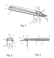
- a sensor arrangement for determining the temperature conditions in the region of a heated by a heat source 16 heating surface 15, such as a glass ceramic heating plate, which between the heat source 16 and the heating surface 15 substantially parallel is arranged to the heating surface 15,
- the sensor arrangement comprises a first sensor 1, which comprises a first support body, in particular comprising ceramic, and at least one disposed on the first support body temperature-dependent first resistance path 23, and the first resistance path 23 of the first sensor 1 of the heating surface 15th facing and is electrically contacted outside of a temperature-sensitive area at a contact point 8, wherein at least one second sensor 2 is provided, which comprises a second support body, in particular comprising ceramic, and at least one disposed on the second support body temperature-dependent second resistance path, which is electrically contacted outside the temperature-sensitive area at a contact point 8, and the second resistance path of the second Sensor of the heat source 16 faces.
- a first measuring sensor 1 is arranged such that, when the measuring sensor arrangement is installed, it comes to lie as flat as possible and directly on the underside of a heating surface 15.
- the use is provided in conjunction with glass ceramic surfaces in kitchen stoves.
- the preferred dimensions therefore depend on the use in such herds.
- the first resistor track 23 and / or the second resistor track have a meandering shape, and are preferably implemented in thick-film technology. Any type of meander shape can be provided. Due to the shape of the meander, the area which is to be resolved particularly sensitively temperature can be determined. It can also be provided no meander. Instead of thick-film technology, which is preferably produced by the screen-printing method, it is also possible to use thin-layer technology or another method.
- first sensor 1 and / or the second sensor 2 are designed substantially identical, resulting in a special savings in terms of parts diversity.
- the second measuring sensor 2 is made larger than the first measuring sensor 1, whereby it shadows the first measuring sensor 1 against the radiant heat of the heat source. This is still positively supported if the second sensor 2 is designed to absorb radiation.
- the temperature measuring range can furthermore be adapted by virtue of the fact that the first resistance path 23 and / or the second resistance path between the contacting point 8 and the temperature-sensitive region have a larger, in particular double, cross section 23a than in the temperature-sensitive region. Larger cross-section means less resistance and lower temperature sensitivity, which may be in demand at the edge.
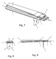
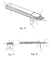
- the probe assembly against the free, facing away from the contact point 8 end rejuvenate. This is the case in the illustrated preferred embodiments. As a result, only a small part of the heat source 16 is shaded with respect to the heating surface 15. In addition, this effect can be assisted by the fact that the sensor arrangement has a widened region 25 in the region of the contact point 8, wherein the transition to the remaining, narrower region 24 of the sensor arrangement is rounded, preferably concave.
- the temperature sensitivity can be adjusted. Therefore, it may be advantageous for a high temperature sensitivity if the length of the first resistance path 23 and / or the second resistance path in the temperature-sensitive region is at least 200 mm.
- the resistance paths must be permanently electrically contacted under strongly changing thermal conditions. It has proven to be particularly advantageous if at least one contacting piece of elastically resilient material is provided for contacting the first resistance path 23 and / or the second resistance path, which is connected to the support body, preferably riveted.
- the resistance path 23 of the first measuring sensor 1 and / or of the second measuring sensor 2 is insulated with a closed, thermally conductive passivation layer.
- a passivation layer can, if it is made thick enough and any bumps such as screw heads and / or rivets 6, 7 hide or cover and thus contribute to a better flatness, especially the first sensor 1, especially on the heating surface 15.
- a holding element 3, 4 can be arranged between the first measuring sensor 2 and the second measuring sensor 3.
- This holding element 3, 4 can be designed as a bracket and / or trough-shaped, wherein preferably in the space spanned by the bracket and / or in the tub 4, an insulating material is arranged.
- the holding element 3, 4 may be made of any thermally stable material, preferably ceramic or stainless steel.
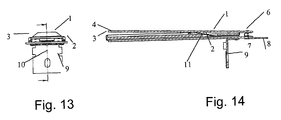
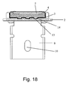
- the pressing of the first probe 1 to the heating surface 15 is supported in a simple manner by a against the first probe 1 supporting the spring tongue 11, 12 which the second sensor 2 and / or the holding element 3, 4 is arranged. Such an arrangement is shown approximately in FIGS. 13 to 17.
- the second sensor 2 is at least partially connected to the holding element 3, 4. This plan is preferably applied to the holding element 3, 4.
- the holding element 3, 4 preferably has the shape of a trapezoidal frame on or a trough 4, wherein the trough 4 may have a trapezoidal or rectangular outline and the bottom and the inside of the trough 4 may preferably be plane-parallel plates.
- the measuring sensors 1, 2 nestle particularly well and advantageously against the holding element 3.
- the holding element 3, 4 preferably has a receptacle for the first measuring sensor 1. This can be provided both in the embodiment as a frame as well as in the tub 4.
- the first measuring sensor 1 rests as flat as possible on the heating surface 15, it can be provided that the first measuring sensor 1, in particular the first supporting body, in the region of the contacting point 8 by means of at least one elastically resilient connecting means, preferably a spring 5, in particular a metal spring, in particular a U-spring or Z-spring, with the second sensor 2 and / or the holding element 3, 4 is connected.
- a spring 5 in particular a metal spring, in particular a U-spring or Z-spring
- thermally stable connecting means are provided, in particular screws and / or rivets 6, 7.
- Rivets to use, as they are permanently solid, thermally stable, cheap and can be mounted automatically.
- the first sensor 1 in the region of the contacting point 8 has a stepped depression, which is lower than the means the thermally stable connection, wherein when completely in the receptacle of the holding member 3, 4 arranged first sensor 1, the first resistance path 23 is arranged substantially parallel to the second resistance path. Due to the stepped reduction, the first sensor 1 can rest flat on the heating surface 15 without this being hindered by the heads of the rivets 6, 7.
- the first support body is designed in several parts in the region of the step-shaped lowering.
- the metrologically important part can be designed as a planar part, which is connected to a further part, and thereby forms a step, as shown for example in FIGS. 7 and 9.
- a substantially angle-shaped retaining clip 9 is preferably provided, which is connected, in particular riveted or screwed, to the second measuring sensor 2 and / or the retaining element 3, 4. If the retaining clip 9 is connected to the retaining element 3, 4, it may be provided in particularly preferred embodiments that the retaining clip 9 has a receptacle, in particular a slide-in receptacle, for the second measuring probe 2, whereby a second measuring probe can be applied in a particularly simple manner.
- a vertically extending slot 10 is preferably provided in a vertical position in use position of the retaining clip 9.
Landscapes
- Chemical & Material Sciences (AREA)
- Engineering & Computer Science (AREA)
- Chemical Kinetics & Catalysis (AREA)
- Textile Engineering (AREA)
- Physics & Mathematics (AREA)
- General Physics & Mathematics (AREA)
- Ceramic Engineering (AREA)
- Measuring Temperature Or Quantity Of Heat (AREA)
Priority Applications (1)
| Application Number | Priority Date | Filing Date | Title |
|---|---|---|---|
| PL06450039T PL1715316T3 (pl) | 2005-04-19 | 2006-03-20 | Układ czujników pomiarowych |
Applications Claiming Priority (1)
| Application Number | Priority Date | Filing Date | Title |
|---|---|---|---|
| AT0024105U AT8257U1 (de) | 2005-04-19 | 2005-04-19 | Messfühleranordnung |
Publications (2)
| Publication Number | Publication Date |
|---|---|
| EP1715316A1 true EP1715316A1 (fr) | 2006-10-25 |
| EP1715316B1 EP1715316B1 (fr) | 2011-01-05 |
Family
ID=35070933
Family Applications (1)
| Application Number | Title | Priority Date | Filing Date |
|---|---|---|---|
| EP06450039A Expired - Lifetime EP1715316B1 (fr) | 2005-04-19 | 2006-03-20 | Dispositif de sonde |
Country Status (5)
| Country | Link |
|---|---|
| US (1) | US7534032B2 (fr) |
| EP (1) | EP1715316B1 (fr) |
| AT (2) | AT8257U1 (fr) |
| DE (2) | DE202005011147U1 (fr) |
| PL (1) | PL1715316T3 (fr) |
Cited By (1)
| Publication number | Priority date | Publication date | Assignee | Title |
|---|---|---|---|---|
| WO2008117909A1 (fr) | 2007-03-28 | 2008-10-02 | Lg Electronics Inc. | Dispositif de détection de la chaleur, appareil de cuisson utilisant ledit dispositif et procédé de régulation de l'appareil de cuisson |
Families Citing this family (8)
| Publication number | Priority date | Publication date | Assignee | Title |
|---|---|---|---|---|
| DE102006016956B4 (de) * | 2006-04-11 | 2009-10-08 | Electrolux Home Products Corp. N.V. | Verfahren zum Bestimmen der von einem Gargut aufgenommenen Wärme in einem Gargerät und Gargerät zur Durchführung des Verfahrens |
| CH701673B1 (de) * | 2010-12-13 | 2014-05-15 | V Zug Ag | Gargerät mit Temperatursicherungseinheit. |
| US8702303B2 (en) | 2011-06-29 | 2014-04-22 | Schneider Electric USA, Inc. | Sensor mounting methodology |
| FR3017457A1 (fr) * | 2014-02-11 | 2015-08-14 | Turbomeca | Dispositif de fixation d'un capteur sur une piece |
| US10018514B2 (en) * | 2014-02-17 | 2018-07-10 | Haier Us Appliance Solutions, Inc. | Cooktop temperature sensors and methods of operation |
| US20160227609A1 (en) * | 2015-01-30 | 2016-08-04 | Schott Corporation | Multi function glass or glass-ceramic cooktop system and method of cooking thereon |
| KR101724499B1 (ko) * | 2015-12-11 | 2017-04-07 | 현대자동차 주식회사 | 입자상 물질 센서 및 이를 이용한 측정방법 |
| CN107889300A (zh) * | 2016-09-29 | 2018-04-06 | 浙江久康电器有限公司 | 插接式红外线电热炉盘及装用该电热炉盘的电加热灶 |
Citations (3)
| Publication number | Priority date | Publication date | Assignee | Title |
|---|---|---|---|---|
| US5258736A (en) * | 1990-07-18 | 1993-11-02 | Schott Glaswerke | Temperature sensor or temperature sensor arrangement made from glass ceramic and bonding film resistors |
| EP1489479A1 (fr) * | 2003-06-16 | 2004-12-22 | Ceramaspeed Limited | Appareil et méthode pour la détection de montée anormale en température dans un appareil de cuisson |
| WO2004111589A1 (fr) * | 2003-06-13 | 2004-12-23 | Ceramaspeed Limited | Ensemble capteur de temperature pour agencement de chauffage electrique |
Family Cites Families (9)
| Publication number | Priority date | Publication date | Assignee | Title |
|---|---|---|---|---|
| DE2913866C2 (de) * | 1979-04-06 | 1987-03-12 | Robert Bosch Gmbh, 7000 Stuttgart | Meßfühler für die Bestimmung von Bestandteilen in strömenden Gasen |
| DE3934157C2 (de) | 1989-10-12 | 1999-01-28 | Bosch Siemens Hausgeraete | Kochmulde |
| DE19906115C1 (de) * | 1999-02-13 | 2000-08-31 | Schott Glas | Verfahren zum Erkennen des Leerkochens von Geschirr bei Kochfeldern mit einer Glaskeramik-Kochfläche und zugehörige Vorrichtung |
| US6746586B2 (en) * | 2000-07-31 | 2004-06-08 | Ngk Spark Plug Co., Ltd. | Multi-layer gas sensor element and gas sensor comprising the same |
| US6588253B2 (en) * | 2001-08-17 | 2003-07-08 | Delphi Technologies, Inc. | Fuel volatitlity sensor and method based on capacitance measurement |
| US6634210B1 (en) * | 2002-04-17 | 2003-10-21 | Delphi Technologies, Inc. | Particulate sensor system |
| ATE332493T1 (de) * | 2004-02-24 | 2006-07-15 | Electrovac | Temperaturmessfühler |
| US7069770B2 (en) * | 2004-08-02 | 2006-07-04 | Delphi Technologies, Inc. | Ammonia sensor element, heater, and method for making the same |
| GB0426467D0 (en) * | 2004-12-02 | 2005-01-05 | Ceramaspeed Ltd | Apparatus for detecting abnormal temperature rise associated with a cooking arrangement |
-
2005
- 2005-04-19 AT AT0024105U patent/AT8257U1/de not_active IP Right Cessation
- 2005-07-15 DE DE202005011147U patent/DE202005011147U1/de not_active Expired - Lifetime
-
2006
- 2006-03-20 AT AT06450039T patent/ATE494533T1/de active
- 2006-03-20 PL PL06450039T patent/PL1715316T3/pl unknown
- 2006-03-20 EP EP06450039A patent/EP1715316B1/fr not_active Expired - Lifetime
- 2006-03-20 DE DE502006008638T patent/DE502006008638D1/de not_active Expired - Lifetime
- 2006-04-18 US US11/379,108 patent/US7534032B2/en not_active Expired - Fee Related
Patent Citations (3)
| Publication number | Priority date | Publication date | Assignee | Title |
|---|---|---|---|---|
| US5258736A (en) * | 1990-07-18 | 1993-11-02 | Schott Glaswerke | Temperature sensor or temperature sensor arrangement made from glass ceramic and bonding film resistors |
| WO2004111589A1 (fr) * | 2003-06-13 | 2004-12-23 | Ceramaspeed Limited | Ensemble capteur de temperature pour agencement de chauffage electrique |
| EP1489479A1 (fr) * | 2003-06-16 | 2004-12-22 | Ceramaspeed Limited | Appareil et méthode pour la détection de montée anormale en température dans un appareil de cuisson |
Cited By (2)
| Publication number | Priority date | Publication date | Assignee | Title |
|---|---|---|---|---|
| WO2008117909A1 (fr) | 2007-03-28 | 2008-10-02 | Lg Electronics Inc. | Dispositif de détection de la chaleur, appareil de cuisson utilisant ledit dispositif et procédé de régulation de l'appareil de cuisson |
| EP2137461B1 (fr) * | 2007-03-28 | 2017-08-16 | LG Electronics Inc. | Appareil de cuisson utilisant un dispositif de détection de chaleur |
Also Published As
| Publication number | Publication date |
|---|---|
| DE202005011147U1 (de) | 2005-09-29 |
| AT8257U1 (de) | 2006-04-15 |
| US20060231546A1 (en) | 2006-10-19 |
| PL1715316T3 (pl) | 2011-06-30 |
| ATE494533T1 (de) | 2011-01-15 |
| US7534032B2 (en) | 2009-05-19 |
| EP1715316B1 (fr) | 2011-01-05 |
| DE502006008638D1 (de) | 2011-02-17 |
Similar Documents
| Publication | Publication Date | Title |
|---|---|---|
| DE4022844C1 (fr) | ||
| EP1715316B1 (fr) | Dispositif de sonde | |
| DE102004059730A1 (de) | Temperaturmesseinrichtung | |
| EP0467133B1 (fr) | Capteur de températures ou dispositif de mesure de la température en céramique de verre pourvu de résistances en couches minces | |
| EP1243904A1 (fr) | Sonde sensible à la température | |
| EP1568980B2 (fr) | Capteur de température | |
| US20060237438A1 (en) | Temperature sensor assembly for an electrical heating arrangement | |
| DE10006974A1 (de) | Kochfeld mit Temperaturfühler | |
| FI57509C (fi) | Temperaturbegraensare | |
| DE602005001501T2 (de) | Elektrische heizanordnung | |
| DE202005008402U1 (de) | Temperatursensoranordnung | |
| DE10006954A1 (de) | Kochfeld mit Temperaturfühler | |
| DE69814877T2 (de) | Elektrischer flussigkeitsheizvorrichtung | |
| EP2775792B1 (fr) | Appareil de cuisson | |
| EP1303169A1 (fr) | Capteur de température utilisant un élément sensible ainsi que son utilisation | |
| DE212011100126U1 (de) | Verbesserter elektronischer und elektro-mechanischer Thermostat | |
| EP2649860B1 (fr) | Dispositif de chauffage pour un appareil électroménager et appareil électroménager équipé de ce dispositif de chauffage | |
| EP3430324B1 (fr) | Système de corps de thermorégulation aux modes de fonctionnement flexibles | |
| DE3033605C2 (de) | Raumthermostat | |
| EP2183758A1 (fr) | Capteur de température | |
| EP2775787B1 (fr) | Appareil de cuisson | |
| DE102013102107A1 (de) | Kocheinrichtung und Verfahren zum Betreiben | |
| AT404923B (de) | Prüfstrahler zur kalibrierung von infrarotdetektoren | |
| JP2007506067A (ja) | 沸騰レベルを制御する方法 | |
| DE102013102112A1 (de) | Kocheinrichtung |
Legal Events
| Date | Code | Title | Description |
|---|---|---|---|
| PUAI | Public reference made under article 153(3) epc to a published international application that has entered the european phase |
Free format text: ORIGINAL CODE: 0009012 |
|
| AK | Designated contracting states |
Kind code of ref document: A1 Designated state(s): AT BE BG CH CY CZ DE DK EE ES FI FR GB GR HU IE IS IT LI LT LU LV MC NL PL PT RO SE SI SK TR |
|
| AX | Request for extension of the european patent |
Extension state: AL BA HR MK YU |
|
| 17P | Request for examination filed |
Effective date: 20070425 |
|
| 17Q | First examination report despatched |
Effective date: 20070524 |
|
| AKX | Designation fees paid |
Designated state(s): AT BE BG CH CY CZ DE DK EE ES FI FR GB GR HU IE IS IT LI LT LU LV MC NL PL PT RO SE SI SK TR |
|
| RAP1 | Party data changed (applicant data changed or rights of an application transferred) |
Owner name: ELECTROVAC AG |
|
| GRAP | Despatch of communication of intention to grant a patent |
Free format text: ORIGINAL CODE: EPIDOSNIGR1 |
|
| GRAS | Grant fee paid |
Free format text: ORIGINAL CODE: EPIDOSNIGR3 |
|
| GRAA | (expected) grant |
Free format text: ORIGINAL CODE: 0009210 |
|
| AK | Designated contracting states |
Kind code of ref document: B1 Designated state(s): AT BE BG CH CY CZ DE DK EE ES FI FR GB GR HU IE IS IT LI LT LU LV MC NL PL PT RO SE SI SK TR |
|
| REG | Reference to a national code |
Ref country code: GB Ref legal event code: FG4D Free format text: NOT ENGLISH |
|
| REG | Reference to a national code |
Ref country code: CH Ref legal event code: EP |
|
| REG | Reference to a national code |
Ref country code: IE Ref legal event code: FG4D Free format text: LANGUAGE OF EP DOCUMENT: GERMAN |
|
| REF | Corresponds to: |
Ref document number: 502006008638 Country of ref document: DE Date of ref document: 20110217 Kind code of ref document: P |
|
| REG | Reference to a national code |
Ref country code: DE Ref legal event code: R096 Ref document number: 502006008638 Country of ref document: DE Effective date: 20110217 |
|
| REG | Reference to a national code |
Ref country code: NL Ref legal event code: VDEP Effective date: 20110105 |
|
| PG25 | Lapsed in a contracting state [announced via postgrant information from national office to epo] |
Ref country code: SI Free format text: LAPSE BECAUSE OF FAILURE TO SUBMIT A TRANSLATION OF THE DESCRIPTION OR TO PAY THE FEE WITHIN THE PRESCRIBED TIME-LIMIT Effective date: 20110105 |
|
| PGFP | Annual fee paid to national office [announced via postgrant information from national office to epo] |
Ref country code: AT Payment date: 20110331 Year of fee payment: 6 |
|
| REG | Reference to a national code |
Ref country code: FR Ref legal event code: CD |
|
| LTIE | Lt: invalidation of european patent or patent extension |
Effective date: 20110105 |
|
| REG | Reference to a national code |
Ref country code: PL Ref legal event code: T3 |
|
| PG25 | Lapsed in a contracting state [announced via postgrant information from national office to epo] |
Ref country code: IS Free format text: LAPSE BECAUSE OF FAILURE TO SUBMIT A TRANSLATION OF THE DESCRIPTION OR TO PAY THE FEE WITHIN THE PRESCRIBED TIME-LIMIT Effective date: 20110505 Ref country code: PT Free format text: LAPSE BECAUSE OF FAILURE TO SUBMIT A TRANSLATION OF THE DESCRIPTION OR TO PAY THE FEE WITHIN THE PRESCRIBED TIME-LIMIT Effective date: 20110505 Ref country code: LV Free format text: LAPSE BECAUSE OF FAILURE TO SUBMIT A TRANSLATION OF THE DESCRIPTION OR TO PAY THE FEE WITHIN THE PRESCRIBED TIME-LIMIT Effective date: 20110105 Ref country code: GR Free format text: LAPSE BECAUSE OF FAILURE TO SUBMIT A TRANSLATION OF THE DESCRIPTION OR TO PAY THE FEE WITHIN THE PRESCRIBED TIME-LIMIT Effective date: 20110406 Ref country code: SE Free format text: LAPSE BECAUSE OF FAILURE TO SUBMIT A TRANSLATION OF THE DESCRIPTION OR TO PAY THE FEE WITHIN THE PRESCRIBED TIME-LIMIT Effective date: 20110105 Ref country code: LT Free format text: LAPSE BECAUSE OF FAILURE TO SUBMIT A TRANSLATION OF THE DESCRIPTION OR TO PAY THE FEE WITHIN THE PRESCRIBED TIME-LIMIT Effective date: 20110105 Ref country code: ES Free format text: LAPSE BECAUSE OF FAILURE TO SUBMIT A TRANSLATION OF THE DESCRIPTION OR TO PAY THE FEE WITHIN THE PRESCRIBED TIME-LIMIT Effective date: 20110416 |
|
| PGFP | Annual fee paid to national office [announced via postgrant information from national office to epo] |
Ref country code: GB Payment date: 20110331 Year of fee payment: 6 Ref country code: FR Payment date: 20110414 Year of fee payment: 6 |
|
| REG | Reference to a national code |
Ref country code: IE Ref legal event code: FD4D |
|
| PG25 | Lapsed in a contracting state [announced via postgrant information from national office to epo] |
Ref country code: BG Free format text: LAPSE BECAUSE OF FAILURE TO SUBMIT A TRANSLATION OF THE DESCRIPTION OR TO PAY THE FEE WITHIN THE PRESCRIBED TIME-LIMIT Effective date: 20110405 Ref country code: FI Free format text: LAPSE BECAUSE OF FAILURE TO SUBMIT A TRANSLATION OF THE DESCRIPTION OR TO PAY THE FEE WITHIN THE PRESCRIBED TIME-LIMIT Effective date: 20110105 Ref country code: NL Free format text: LAPSE BECAUSE OF FAILURE TO SUBMIT A TRANSLATION OF THE DESCRIPTION OR TO PAY THE FEE WITHIN THE PRESCRIBED TIME-LIMIT Effective date: 20110105 Ref country code: CY Free format text: LAPSE BECAUSE OF FAILURE TO SUBMIT A TRANSLATION OF THE DESCRIPTION OR TO PAY THE FEE WITHIN THE PRESCRIBED TIME-LIMIT Effective date: 20110105 |
|
| PGFP | Annual fee paid to national office [announced via postgrant information from national office to epo] |
Ref country code: PL Payment date: 20110404 Year of fee payment: 6 |
|
| BERE | Be: lapsed |
Owner name: ELECTROVAC AG Effective date: 20110331 |
|
| PGFP | Annual fee paid to national office [announced via postgrant information from national office to epo] |
Ref country code: DE Payment date: 20110526 Year of fee payment: 6 |
|
| PG25 | Lapsed in a contracting state [announced via postgrant information from national office to epo] |
Ref country code: IE Free format text: LAPSE BECAUSE OF FAILURE TO SUBMIT A TRANSLATION OF THE DESCRIPTION OR TO PAY THE FEE WITHIN THE PRESCRIBED TIME-LIMIT Effective date: 20110105 Ref country code: MC Free format text: LAPSE BECAUSE OF NON-PAYMENT OF DUE FEES Effective date: 20110331 Ref country code: DK Free format text: LAPSE BECAUSE OF FAILURE TO SUBMIT A TRANSLATION OF THE DESCRIPTION OR TO PAY THE FEE WITHIN THE PRESCRIBED TIME-LIMIT Effective date: 20110105 Ref country code: EE Free format text: LAPSE BECAUSE OF FAILURE TO SUBMIT A TRANSLATION OF THE DESCRIPTION OR TO PAY THE FEE WITHIN THE PRESCRIBED TIME-LIMIT Effective date: 20110105 |
|
| REG | Reference to a national code |
Ref country code: CH Ref legal event code: PL |
|
| PLBE | No opposition filed within time limit |
Free format text: ORIGINAL CODE: 0009261 |
|
| STAA | Information on the status of an ep patent application or granted ep patent |
Free format text: STATUS: NO OPPOSITION FILED WITHIN TIME LIMIT |
|
| PG25 | Lapsed in a contracting state [announced via postgrant information from national office to epo] |
Ref country code: RO Free format text: LAPSE BECAUSE OF FAILURE TO SUBMIT A TRANSLATION OF THE DESCRIPTION OR TO PAY THE FEE WITHIN THE PRESCRIBED TIME-LIMIT Effective date: 20110105 Ref country code: SK Free format text: LAPSE BECAUSE OF FAILURE TO SUBMIT A TRANSLATION OF THE DESCRIPTION OR TO PAY THE FEE WITHIN THE PRESCRIBED TIME-LIMIT Effective date: 20110105 Ref country code: CZ Free format text: LAPSE BECAUSE OF FAILURE TO SUBMIT A TRANSLATION OF THE DESCRIPTION OR TO PAY THE FEE WITHIN THE PRESCRIBED TIME-LIMIT Effective date: 20110105 |
|
| 26N | No opposition filed |
Effective date: 20111006 |
|
| PG25 | Lapsed in a contracting state [announced via postgrant information from national office to epo] |
Ref country code: BE Free format text: LAPSE BECAUSE OF NON-PAYMENT OF DUE FEES Effective date: 20110331 Ref country code: IT Free format text: LAPSE BECAUSE OF FAILURE TO SUBMIT A TRANSLATION OF THE DESCRIPTION OR TO PAY THE FEE WITHIN THE PRESCRIBED TIME-LIMIT Effective date: 20110105 |
|
| PG25 | Lapsed in a contracting state [announced via postgrant information from national office to epo] |
Ref country code: CH Free format text: LAPSE BECAUSE OF NON-PAYMENT OF DUE FEES Effective date: 20110331 Ref country code: LI Free format text: LAPSE BECAUSE OF NON-PAYMENT OF DUE FEES Effective date: 20110331 |
|
| REG | Reference to a national code |
Ref country code: DE Ref legal event code: R097 Ref document number: 502006008638 Country of ref document: DE Effective date: 20111006 |
|
| GBPC | Gb: european patent ceased through non-payment of renewal fee |
Effective date: 20120320 |
|
| REG | Reference to a national code |
Ref country code: AT Ref legal event code: MM01 Ref document number: 494533 Country of ref document: AT Kind code of ref document: T Effective date: 20120320 |
|
| REG | Reference to a national code |
Ref country code: FR Ref legal event code: ST Effective date: 20121130 |
|
| PG25 | Lapsed in a contracting state [announced via postgrant information from national office to epo] |
Ref country code: FR Free format text: LAPSE BECAUSE OF NON-PAYMENT OF DUE FEES Effective date: 20120402 Ref country code: AT Free format text: LAPSE BECAUSE OF NON-PAYMENT OF DUE FEES Effective date: 20120320 Ref country code: GB Free format text: LAPSE BECAUSE OF NON-PAYMENT OF DUE FEES Effective date: 20120320 |
|
| REG | Reference to a national code |
Ref country code: DE Ref legal event code: R119 Ref document number: 502006008638 Country of ref document: DE Effective date: 20121002 |
|
| PG25 | Lapsed in a contracting state [announced via postgrant information from national office to epo] |
Ref country code: PL Free format text: LAPSE BECAUSE OF NON-PAYMENT OF DUE FEES Effective date: 20120320 Ref country code: LU Free format text: LAPSE BECAUSE OF NON-PAYMENT OF DUE FEES Effective date: 20110320 |
|
| REG | Reference to a national code |
Ref country code: PL Ref legal event code: LAPE |
|
| PG25 | Lapsed in a contracting state [announced via postgrant information from national office to epo] |
Ref country code: TR Free format text: LAPSE BECAUSE OF FAILURE TO SUBMIT A TRANSLATION OF THE DESCRIPTION OR TO PAY THE FEE WITHIN THE PRESCRIBED TIME-LIMIT Effective date: 20110105 |
|
| PG25 | Lapsed in a contracting state [announced via postgrant information from national office to epo] |
Ref country code: HU Free format text: LAPSE BECAUSE OF FAILURE TO SUBMIT A TRANSLATION OF THE DESCRIPTION OR TO PAY THE FEE WITHIN THE PRESCRIBED TIME-LIMIT Effective date: 20110105 |
|
| PG25 | Lapsed in a contracting state [announced via postgrant information from national office to epo] |
Ref country code: DE Free format text: LAPSE BECAUSE OF NON-PAYMENT OF DUE FEES Effective date: 20121002 |