EP0621739B1 - Système de cuisson - Google Patents
Système de cuisson Download PDFInfo
- Publication number
- EP0621739B1 EP0621739B1 EP19940105554 EP94105554A EP0621739B1 EP 0621739 B1 EP0621739 B1 EP 0621739B1 EP 19940105554 EP19940105554 EP 19940105554 EP 94105554 A EP94105554 A EP 94105554A EP 0621739 B1 EP0621739 B1 EP 0621739B1
- Authority
- EP
- European Patent Office
- Prior art keywords
- cooking
- temperature
- thermostat
- reed
- cookware
- Prior art date
- Legal status (The legal status is an assumption and is not a legal conclusion. Google has not performed a legal analysis and makes no representation as to the accuracy of the status listed.)
- Expired - Lifetime
Links
Images

Classifications
-
- H—ELECTRICITY
- H05—ELECTRIC TECHNIQUES NOT OTHERWISE PROVIDED FOR
- H05B—ELECTRIC HEATING; ELECTRIC LIGHT SOURCES NOT OTHERWISE PROVIDED FOR; CIRCUIT ARRANGEMENTS FOR ELECTRIC LIGHT SOURCES, IN GENERAL
- H05B1/00—Details of electric heating devices
- H05B1/02—Automatic switching arrangements specially adapted to apparatus ; Control of heating devices
- H05B1/0202—Switches
- H05B1/0208—Switches actuated by the expansion or evaporation of a gas or liquid
-
- A—HUMAN NECESSITIES
- A47—FURNITURE; DOMESTIC ARTICLES OR APPLIANCES; COFFEE MILLS; SPICE MILLS; SUCTION CLEANERS IN GENERAL
- A47J—KITCHEN EQUIPMENT; COFFEE MILLS; SPICE MILLS; APPARATUS FOR MAKING BEVERAGES
- A47J27/00—Cooking-vessels
- A47J27/002—Construction of cooking-vessels; Methods or processes of manufacturing specially adapted for cooking-vessels
-
- H—ELECTRICITY
- H05—ELECTRIC TECHNIQUES NOT OTHERWISE PROVIDED FOR
- H05B—ELECTRIC HEATING; ELECTRIC LIGHT SOURCES NOT OTHERWISE PROVIDED FOR; CIRCUIT ARRANGEMENTS FOR ELECTRIC LIGHT SOURCES, IN GENERAL
- H05B6/00—Heating by electric, magnetic or electromagnetic fields
- H05B6/02—Induction heating
- H05B6/10—Induction heating apparatus, other than furnaces, for specific applications
- H05B6/12—Cooking devices
Definitions
- the invention relates to a cooking system consisting of a Hob and cookware.
- the object of the invention is to provide an induction cooking system create, which ensures that a temperature sensitive Cooking surface (e.g. made of wood, plastic, ceramic, Slate, marble or granite) no impermissibly high temperatures assumes.
- a temperature sensitive Cooking surface e.g. made of wood, plastic, ceramic, Slate, marble or granite
- cookware should be available be made with the induction cooker according to the invention a temperature-controlled cooking process is possible.
- FR-A-2 417 725 discloses a Induction hob, where an induction coil is located directly on the underside of the hob is arranged. Between the underside of the hob with the induction coil and for the induction heating necessary switching and control elements is a gap in which a cooling air flow is caused by a fan.
- Cookware is also known, which has an insulating Layer on the floor or on the walls are covered (DE 2453169, A1, DE 2906912 A1). This will save energy as well also causes the temperature transfer to the hob is reduced, making it particularly temperature-sensitive Cooking surfaces should be protected. With these known However, systems can still overheat the hob occur because, on the one hand, effective heat dissipation Cooling the cooking surface is not provided, on the other hand Cookware can be overheated because of the insulating layer temperature control via the cooktop is not possible.
- the first part of the invention task overheating the temperature sensitive This excludes the cooking surface solved that a heat insulating layer between the top the cooking surface and the heating base of the cookware is arranged, and between induction coil and bottom there is a gap in the cooktop in which a Cooling air flow is caused by a powerful blower that directly connected to the open center of the induction coil is.
- the thermal conductivity of the insulating layer should be as possible be smaller than that of the cooking surface itself, so that the largest Part of the heat gradient between the bottom of the cookware and the cooled one Cooking surface underside lies in the heat-insulating layer.
- Such an arrangement is the cooking surface, effective cooling provided that they are lukewarm even when roasting. Furthermore energy is saved, an advantage that also with inductive cooking can be used on ceramic hobs.
- the heat-insulating layer can be on the top of the hob be upset. It then marks the cooking area at the same time. It is advantageous that no special cookware is required becomes. But you can also at least on the ground from the outside, if necessary also be applied to the walls of the cookware. This has the Advantage that the cooking surface is seamless with the kitchen worktop continuous, smooth surface forms, the cooking area through color marking, sandblasting, small spacer knobs or the like. can be marked. Such a coated cookware is also particularly table-friendly. The heat transfer to the Table top is greatly reduced, scratches are excluded. You can touch anywhere without getting burned.
- the arrangement of the cooling on the suction side has the advantage that the cooling air first the cooking surface cools and then the heat loss of the Blower motor leads away, so that the results in the lowest possible cooling air temperature. It can save space the drive motor of the cooling fan as an external rotor motor trained and closed in the central suction opening of the Fan wheel can be arranged.
- the outlet side of the cooling fan can then still be used in the power supply for the induction coil, so that no own cooling fan is required.
- the cooking surface which is only approx. 2-4 mm Starch, it can be provided with ribs on its underside radial, the cooling air gap of approx. 2-3 mm Bridge the thickness and connect or glue it to the induction coil are.
- the Solution in a cookware temperature control device starting from the bottom of the cookware consists, under the hob at least one magnetically operable contact (reed contact) is arranged as a switching point for the power supply, and a liquid-filled temperature sensor is provided, the side of the floor or in a horizontal hole in the Bottom of the cookware is arranged and when heated over the set temperature beyond an expansion body a permanent magnet on the side of the cookware moved, e.g. raises and so operates the contact that the Cooking power switches off, and when the set value is undershot Temperature moved the permanent magnet back again, e.g. lowers so that the contact switches the cooking power on again.
- a permanent magnet on the side of the cookware moved, e.g. raises and so operates the contact that the Cooking power switches off, and when the set value is undershot Temperature moved the permanent magnet back again, e.g. lowers so that the contact switches the cooking power on again.
- This part of the invention can be applied to all cooking systems be, whose cooking surfaces for magnetic and / or electrical Fields are permeable.
- the temperature of the food has already been proposed (US Pat. No. 4,617,441) to regulate with a light signal through the cooking surface.
- US Pat. No. 4,617,441 to regulate with a light signal through the cooking surface.
- the temperature of the bottom of the cookware is not measured, but a skewer as a temperature sensor in the food stuck, a process that is due to the residual heat in the cookware bottom a lower control accuracy results and also no dry-running protection offers.
- a special device for automatic Closing the light passage opening in the cooking surface if the optical signal transmitter is removed and its own power supply required while the subject of the invention is full Offers dry-run protection as well as purely mechanical and on a continuous basis Cooktop works.
- There are already heating outputs for Dine with permanent magnets and responsive contacts been switched (WO 89/04543).
- the permanent magnet moved by hand for purely switching purposes and not as in the invention, by the temperature of the bottom of the cookware for the purpose of temperature control.
- the liquid-filled expansion body or temperature sensor can be on the outside of the cookware jacket near the floor or in a floor hole attached and with the permanent magnet to a structural Unit can be summarized so that such cookware with temperature control as a unit, without and with lid, full is operational.
- the temperature control device on the cookware and the reed contact can also be carried out with the reverse mode of action, i.e. so that the permanent magnet switches off the cooking power when it the cooking surface above the reed contact is approximated. Also a continuous control can be provided instead of a clock control become.
- Temperature sensor switching magnet and temperature setting device existing thermostat no longer as a handle of the cookware, but designed as an autonomous permanent unit so that it can be used for cookware various sizes and types (pots, casseroles, pans) can be used, and preferably on the cookware by a rigidly attached to the thermostat and containing the temperature sensor Cladding tube attached that in about to the center of the cookware extensive or even continuous horizontal drilling can be plugged into the bottom of the cookware (plug-in thermostat).
- Detachable fasteners (permanent magnets, Snap mechanisms, screw mechanisms and the like) are provided, the plug-in thermostats on the cookware hold firmly, the fastening means can be designed so that they act as a switch-on lock so that the temperature-dependent Lateral movement or rotary movement of the switching magnet or the reed contact is only influenced by the switching magnet is possible if the plug-in thermostat is properly connected to the cookware is attached.
- the temperature sensor arranged in the cladding tube can also be used as an expansion rod be formed that the switching magnet temperature-dependent moves and their coefficient of thermal expansion is different from that of the cladding tube differs.
- the magnetic excitation in the Reed contact can be changed. This can be done either through change the distance of the switching magnet to the reed contact (lateral movement) or by changing the angle between the north-south axis of the switching magnet and the axis of the reed contact (rotary movement) or by a combination of both types of movement. in the In the case of the rotary movement, space and energy are required for the movement of the switching magnet in the plug-in thermostat compared to the lateral movement somewhat reduced.
- switching magnet instead of the switching magnet, one can also be inserted in the plug-in thermostat ferromagnetic shielding between switching magnet and reed contact be moved depending on the temperature.
- the plug-in thermostat is attached to the cookware, as long as the bottom of the cookware is ferromagnetic, the simplest and most conveniently by two to the right and left of the cladding tube permanent magnets attached to the housing of the plug-in thermostat, which also secure the plug-in thermostat against twisting.
- other detachable ones must Fasteners such as snap mechanisms, screw mechanisms and the like are used.
- the Fasteners are designed so that they e.g. by Blocking the movement of the switching magnet, as a switch-on lock act as long as the plug-in thermostat does not comply with the regulations is attached to the cookware. This lockout will not needed when the hob, as is often the case today, is equipped with a pot detection device, which the The cooking power switches off automatically when the cookware is removed from the Cooktop is removed.
- the plug-in thermostat When it comes to practical handling in the kitchen, it must work of the cooking system, that the plug-in thermostat is placed sufficiently precisely over the reed contact whose button is marked on the hob.
- the cooktop over the Reed contact must also be provided with a hump that fits into a appropriate recess in the bottom of the plug-in thermostat engages.
- An even better, but also somewhat more expensive solution consists of pushing the reed contact button through several, side by side arranged, electrically connected reed contacts to enlarge. Then it comes down to an exact placement of the plug-in thermostat no more.
- the reed contact as a reed relay and by a timer located under the ICochfeld causes that as Interval switch works and periodically an electrical DC voltage for a certain period of time to the coil of the Reed relays apply their direct current as weak magnetic Counterexcitation to the field of the switching magnet acts on the reed contact, which, however, is not enough to operate the reed contact. It works in connection with the field of the switching magnet switching off the cooking power when the switching magnet is too only slightly from the switch-on position towards the switch-off position has moved.
- the reed contacts are connected in parallel arranged side by side and are designed as reed relays, then the reed contacts with their axis absolutely perpendicular to the hob so that only one connecting lug of each reed contact is in the effective range of the switching magnet. Only then is it guaranteed that the field of the switching magnet, regardless of its placement, always runs in the same direction in all reed contacts, and against the direction of the periodically applied DC excitation in the coils of the reed relays.
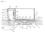
- the kitchen worktop 1 schematically shows an example of a system structure according to the invention.
- the kitchen worktop 1 has a cutout 2 from below, into which the induction coil 3 with the yoke body 4 for the induction field is inserted on a common carrier, not shown.
- the milling 2 is completed at the top by the standing cooking surface 5.
- the cookware 6 consisting of material suitable for inductive heating stands on the cooking surface 5.
- the heat-insulating layer 7 is applied to the bottom and walls of the cookware 6 from the outside. This tableware-friendly cookware, which keeps the food warm for a long time and no longer scratches the surface, can be touched anywhere without being burned.
- the cooling air flow indicated by arrows is drawn in from the center of the induction coil 3 through the closed radial fan wheel 8 of the fan 9.
- the cooling air enters from the periphery into the narrow gap 10 between the induction coil 3 and the underside of the cooking surface 5.
- the blow-out opening 11 of the cooling fan 9 is led to the induction power supply 12, to which the induction coil 3 is connected, so that the components located therein are also cooled by the same fan 9.
- the milling 2 can be carried out such that radially extending ribs (not shown) remain on the underside of the cooking surface 5, which bridge the air gap 10 and are connected or glued to the induction coil 3.
- This firm connection between the cooking surface 5 and the induction coil 3 increases the stability of the cooking surface 5 without the cooling air flow (arrows) being appreciably impaired thereby.
- the ribs even improve the cooling effect.
- the induction power supply 12th can switch on and off.
- the permanent magnet above it in the handle 15 of the cookware 6 16 which, depending on the distance, closes the reed contact 14 or opens.
- the cookware 6 has one for inductive heating suitable floor 17, in a manner known per se for uniformity the temperature is particularly thick (up to approx. 10 mm) is executed.
- the horizontal is in the bottom 17 Bore 18 introduced into which the liquid-filled temperature sensor 19 is inserted over the capillary 20 onto the expansion body 21 acts.
- the permanent magnet 16 is from the expansion body 21 raised above the linkage 22 and actuates the Reed contact 14 as soon as the temperature exceeds the setpoint. This temperature setpoint is set by the rotary knob 23, the preload of the compression spring 25 via the eccentric disk 24 certainly.
- the entire mechanism is in the side of the cookware 6 attached handle 15 housed, which is also from the heat insulating Layer 7 is coated.
- the temperature cycle control of the achievable with this arrangement Cooked food is particularly sensitive because it is on the underside of the Cookware base 17 generated heat the temperature sensor 19 earlier reached as the cookware.
- a magnetic field measuring device (not shown) is also arranged be the cooking power when lifting the permanent magnet 16 reduced proportionally with increasing distance and when lowering accordingly proportionally increased again.
- the resulting steady Temperature control is unsurpassed accuracy.
- Fig. 2 shows an embodiment of the subject of the invention with conventional heating and plug-in thermostat.
- the cookware 32 On the ceramic hob 31 is the cookware 32 with the cookware base 33, which is designed in the usual way as a relatively thick sandwich construction and has a bore 34 for receiving the cladding tube 35 of the plug-in thermostat.
- the cladding tube 35 is itself designed as a temperature sensor and divided on the inside by a partition wall 36 such that only the front part contains liquid 37 and the capillary 38 already begins inside the cladding tube 35 on the partition wall 36.
- the capillary 38 guides the liquid 37, which expands when the temperature rises, into the expansion box 39, which is supported on the ball 40 and via which lever mechanism 41, which strongly converts the expansion movement of the box 39, raises and lowers the switching magnet 42 in a temperature-dependent manner.
- the target temperature is set on the rotary knob 43.
- the ball 40 is provided with a spring 44 so that it can deflect in the event of an overload.
- the casing tube 35 is rigidly anchored, for example soldered, in the housing 45 of the plug-in thermostat, which can be made watertight to be dishwasher-proof.
- a permanent magnet 46 is attached to its housing 45 on both sides of the cladding tube 35 for detachable mounting of the plug-in thermostat on the cookware 32 and as protection against rotation.
- Underneath is the electric heater 47 of the hob 31 with the reflector 48, which adjusts the cooking power of the heater 47 directs above.
- the heating 47 is switched on and off by the power relay 49 switched off, which is actuated by the reed contacts 50, the are electrically connected in parallel.
- To enlarge the reed contact button three reed contacts 50 are arranged side by side, and you can tell by the roughly scaled figure, that the switching magnet 42 is shifted about 1.5 cm in all directions can be made without its influence on the reed contacts 50 to lose.
- the button can be enlarged as required.
- the three reed contacts 50 are vertically next to each other underneath arranged the hob 31 and designed as a reed relay, i.e. she contain electrical coils 51 through which to influence the Switching behavior can be sent a direct current, the one weak, the magnetic field of the switching magnet 42 opposite Magnetic field generated. This happens periodically through the interval switch operating time relay 52, the contact of which e.g. each closed for 10 sec and open for 15 sec. These time constants are based on the design-related thermal inertia behavior the hob 31 with heater 47 and reflector 48 to coordinate. Each the hob 31 is slower, i.e. the longer the after-heat is effective is, the greater should be those set at interval switch 52 Periods of time.
- the level of the direct current in the coils 51 and thus the strength of the opposing magnetic field can depend on the variable resistor 53 are regulated and must be set so that already with a slight lifting of the switching magnet 42, the reed contacts 50 open, with further removal of the switching magnet 42 from the opposing field alone cannot be closed again.
- the circuit can of course be used in the frame the electronics mostly present in the stove anyway with even less Effort can also be set up without contact.
Claims (10)
- Système de cuisson, composé d'une zone de cuisson à induction dont la surface de cuisson (5) se compose de matériau sensible à la température, de préférence du bois, du plastique, de la céramique, de l'ardoise, du marbre ou du granit, et qui est refroidie par le dessous, ainsi qu'un récipient de cuisson (6) adapté au chauffage par induction, caractérisé par le fait qu'une couche d'isolation thermique (7) est disposée entre le dessus de la surface de cuisson (5) et le fond chauffé du récipient de cuisson (6), et entre la bobine d'induction (3) et le dessous de la surface de cuisson (5) se trouve un espace (10) dans lequel est provoqué un courant d'air de refroidissement par un ventilateur (8, 9) à haute pression, lequel est relié directement au centre ouverte de la bobine d'induction (3), le ventilateur (8, 9) ventant de préférence se raccorder au centre ouverte de la bobine d'induction (3) par son orifice d'aspiration.
- Système de cuisson selon la revendication 1, caractérisé par le fait que le côté soufflage (11) du ventilateur (8, 9) est acheminé dans l'alimentation électrique (12) de la bobine d'induction (3) et le dessous de la surface de cuisson (5) est muni de rainures qui s'étendent dans le sens radial et qui sont reliées à la bobine d'induction (3).
- Système de cuisson selon les revendications 1 et 2, caractérisé par le fait qu'au moins un contact magnétique (14) (contact Reed) est prévu sous la zone de cuisson qui fait office de point de commutation pour une arrivée de puissance, et qu'il est prévu un capteur de température (19) qui est disposé latéralement sur le fond ou dans un orifice horizontal (18) dans le fond du récipient de cuisson (6) et qui, lorsqu'il s'échauffe au-dessus d'une température donnée, déplace par le biais d'un corps de dilatation (21) un aimant permanent (16) disposé sur le côté du récipient de cuisson (6) et actionne ainsi le contact (14) qui coupe la puissance de cuisson, et qui déplace à nouveau l'aimant permanent (16) lorsque la température devient inférieure à la température réglée de manière à ce que le contact (14) rétablisse la puissance de cuisson.
- Système de cuisson selon la revendication 3, caractérisé par le fait que l'aiment permanent (16) du dispositif de régulation de la température de cuisson, suivant la position rotative du récipient de cuisson (6), agit sur différents contacts (14) qui commutent les différents étages de puissance de l'alimentation électrique.
- Système de cuisson selon la revendication 3, caractérisé par le fait qu'un thermostat, composé essentiellement d'un capteur de température (35), d'un aimant de commutation (42) et d'un dispositif de réglage de la température (40, 43), est réalisé sous la forme d'une unité autonome de manière à pouvoir être utilisé pour des récipients de cuisson de différentes tailles et natures, et il est monté sur le récipient de cuisson (32), de préférence par un tube de gainage (35) fixé à demeure au thermostat et contenant le capteur de température, lequel peut être fiché dans l'orifice horizontal (34) qui s'éxtend environ jusqu'au centre ou même jusqu'au fond du récipient de cuisson (33), et que sont prévus des moyens de fixation amovibles qui maintiennent le thermostat enfichable sur le récipient de cuisson (32), les moyens de fixation pouvant être réalisés de telle façon qu'ils agissent comme des dispositifs de blocage de la mise sous tension de manière à ce que le mouvement latéral ou le mouvement rotatif de l'aimant de commutation (42) en fonction de la température ou l'influence du contact Reed (50) par l'aimant de commutation (42) n'est possible que si le thermostat enfichable est fixé au récipient de cuisson (32) conformément aux instructions.
- Système de cuisson selon la revendication 5, caractérisé par un tube de gainage (35) qui est lui-même réalisé sous la forme d'un capteur de température et qui est séparé à l'intérieur par un paroi de séparation (36) de manière à ce que seule la partie avant contienne du liquide (37) et le capillaire (38) commence déjà à l'intérieur du tube de gainage (35) au niveau de la paroi de séparation (36).
- Système de cuisson selon la revendication 5, caractérisé par le fait que le capteur de température logé dans le tube de gainage (35) est réalisé sous la forme d'une tige de dilatation qui déplace l'aimant de commutation (42) en fonction de la température et dont le coefficient de dilatation thermique est différent de celui du tube de gainage (35).
- Système de cuisson selon la revendication 5, caractérisé par le fait que ce n'est pas l'aimant de commutation (42) qui est déplacé dans le thermostat en fonction de la température, mais un blindage ferromagnétique entre l'aimant de commutation (42) et le contact Reed (50).
- Système de cuisson selon la revendication 5, caractérisé par le fait que pour faciliter le positionnement correct du thermostat enfichable sur la surface de commutation du contact Reedsoit la zone de cuisson (31) au-dessus du contact Reed (50) est munie d'une bosse qui pénètre dans un évidement correspondant dans le fond du thermostat enfichable,soit la surface de commutation du contact Reed est agrandie par plusieurs contacts Reed (50) disposés les uns à côté des autres et branchés en parallèle.
- Système de cuisson selon la revendication 5, caractérisé par la configuration du contact Reed (50) sous la forme d'un relais Reed et un commutateur temporisé (52) disposé sous la zone de cuisson (31), lequel fonctionne comme un commutateur cyclique et applique périodiquement une tension électrique continue pendant une période donnée à la bobine (51) du relais Reed, dont le courant continu agit sur le contact Reed (50) comme une faible contre-excitation magnétique au champ d'aimant permanent (42), lequel n'est cependant pas suffisant à lui tout seul pour actionner le contact Reed (50).
Applications Claiming Priority (4)
| Application Number | Priority Date | Filing Date | Title |
|---|---|---|---|
| DE4312975 | 1993-04-21 | ||
| DE4312975A DE4312975C1 (de) | 1993-04-21 | 1993-04-21 | Induktions-Koch-System mit Kochgeschirr |
| DE4410263 | 1994-03-24 | ||
| DE4410263A DE4410263A1 (de) | 1993-04-21 | 1994-03-24 | Kochsystem mit Kochgeschirr |
Publications (3)
| Publication Number | Publication Date |
|---|---|
| EP0621739A2 EP0621739A2 (fr) | 1994-10-26 |
| EP0621739A3 EP0621739A3 (fr) | 1994-11-30 |
| EP0621739B1 true EP0621739B1 (fr) | 1999-11-03 |
Family
ID=25925110
Family Applications (1)
| Application Number | Title | Priority Date | Filing Date |
|---|---|---|---|
| EP19940105554 Expired - Lifetime EP0621739B1 (fr) | 1993-04-21 | 1994-04-11 | Système de cuisson |
Country Status (2)
| Country | Link |
|---|---|
| EP (1) | EP0621739B1 (fr) |
| ES (1) | ES2141175T3 (fr) |
Cited By (1)
| Publication number | Priority date | Publication date | Assignee | Title |
|---|---|---|---|---|
| CN105144535A (zh) * | 2013-07-17 | 2015-12-09 | 皇家飞利浦有限公司 | 具有接收器的温度控制的无线感应功率输送 |
Families Citing this family (6)
| Publication number | Priority date | Publication date | Assignee | Title |
|---|---|---|---|---|
| DE19604436A1 (de) * | 1996-02-07 | 1997-08-14 | Bosch Siemens Hausgeraete | Muldenplatteninduktor |
| DE19754851A1 (de) | 1997-12-10 | 1999-06-17 | Herchenbach Wolfgang | Kochsystem |
| DE102005030164B3 (de) * | 2005-06-29 | 2006-08-10 | Herchenbach, Wolfgang, Dr. | Kochsystem |
| DE102009043246B3 (de) * | 2009-09-28 | 2011-05-05 | Herchenbach, Wolfgang, Dr. | Kochsystem |
| DE102011000278A1 (de) * | 2011-01-21 | 2012-07-26 | DESIGNquadrat GbR (vertretungsberechtigte Gesellschafter Alexander Christ, 50679 Köln, Guido Endert, 42799 Leichlingen, Horst Wergen, 42105 Wuppertal) | Induktionsherd |
| ES2633612B1 (es) * | 2016-03-21 | 2018-07-04 | Bsh Electrodomésticos España, S.A. | Dispositivo de campo de cocción |
Family Cites Families (12)
| Publication number | Priority date | Publication date | Assignee | Title |
|---|---|---|---|---|
| US3384195A (en) * | 1955-04-15 | 1968-05-21 | Sunbeam Corp | Electric frying pan |
| DE1920778A1 (de) * | 1969-04-24 | 1970-12-17 | Licentia Gmbh | Ferneinstellbarer Temperaturregler |
| DE2306037A1 (de) * | 1973-02-08 | 1974-08-15 | Environment One Corp | Elektrischer kuechenherd |
| GB2010054A (en) * | 1977-08-12 | 1979-06-20 | Ti Group Services Ltd | Electric cooker |
| DE2806794C2 (de) * | 1978-02-17 | 1984-10-25 | Bosch-Siemens Hausgeräte GmbH, 7000 Stuttgart | Kochherd |
| DE2906912A1 (de) | 1979-02-22 | 1980-09-04 | Sachs Systemtechnik Gmbh | Kochgefaess fuer ein induktions-kochgeraet |
| US4617441A (en) | 1983-07-08 | 1986-10-14 | Sanyo Electric Co., Ltd. | Temperature controlled induction heating and cooking apparatus |
| FR2588711A1 (fr) * | 1985-10-11 | 1987-04-17 | Cableco Sa | Plaque pour foyer de cuisson a chauffage a induction et ustensile de cuisine utilisable avec un tel foyer |
| JPS6472490A (en) * | 1987-09-11 | 1989-03-17 | Toshiba Corp | Table with electromagnetic cooker |
| GB8725737D0 (en) | 1987-11-03 | 1987-12-09 | Electrolux Ab | Control apparatus |
| DE3817438A1 (de) | 1988-05-21 | 1989-11-30 | Schock & Co Gmbh | Induktionskochfeld |
| DE3828714A1 (de) | 1988-08-24 | 1990-04-26 | Rudi Redmer | Vorrichtung zum erwaermen von speisen und/oder getraenken |
-
1994
- 1994-04-11 ES ES94105554T patent/ES2141175T3/es not_active Expired - Lifetime
- 1994-04-11 EP EP19940105554 patent/EP0621739B1/fr not_active Expired - Lifetime
Cited By (2)
| Publication number | Priority date | Publication date | Assignee | Title |
|---|---|---|---|---|
| CN105144535A (zh) * | 2013-07-17 | 2015-12-09 | 皇家飞利浦有限公司 | 具有接收器的温度控制的无线感应功率输送 |
| CN105144535B (zh) * | 2013-07-17 | 2017-07-11 | 皇家飞利浦有限公司 | 无线功率输送系统及其功率接收器和操作方法 |
Also Published As
| Publication number | Publication date |
|---|---|
| ES2141175T3 (es) | 2000-03-16 |
| EP0621739A2 (fr) | 1994-10-26 |
| EP0621739A3 (fr) | 1994-11-30 |
Similar Documents
| Publication | Publication Date | Title |
|---|---|---|
| EP3196175B1 (fr) | Plaque de cuisson en vitrocéramique comprenant un capteur infrarouge | |
| US4778978A (en) | Cooking unit with radiant heaters | |
| EP0637898B1 (fr) | Plan de travail et de cuisson | |
| DE4004129A1 (de) | Einrichtung zum erkennen eines in einer heizzone eines koch- oder waermegeraetes aufgestellten kochgefaesses | |
| EP0853444A2 (fr) | Système à cuire avec une plaque de cuisson électrique, transférant la chaleur par conduction | |
| DE4312975C1 (de) | Induktions-Koch-System mit Kochgeschirr | |
| EP0621739B1 (fr) | Système de cuisson | |
| CH654397A5 (de) | Elektrischer kochherd. | |
| WO1987001794A1 (fr) | Dispositif de chauffage uniforme de locaux | |
| EP1715316B1 (fr) | Dispositif de sonde | |
| DD141330A5 (de) | Buegeleinrichtung fuer industrielle verwendung und zugehoeriges buegeleisen | |
| DE3117205A1 (de) | Optoelektronische kochfeldsteuerung | |
| EP1421326A1 (fr) | Appareil menager | |
| DE3739943A1 (de) | Thermische schutzanordnung fuer ein kochfeld mit massiver glasscheibe | |
| CH695817A5 (de) | Bratgerät. | |
| EP0922424B1 (fr) | Système de cuisson | |
| EP1255420A2 (fr) | Dispositif d'affichage | |
| EP1458003B1 (fr) | Capteur de température | |
| DE10242099B4 (de) | Kochfeld | |
| CN210511793U (zh) | 集成灶控制装置 | |
| DD251496A5 (de) | Gargefaess | |
| EP0079483A1 (fr) | Dispositif de commande pour une plaque de cuisson électrique | |
| EP0813031B1 (fr) | Plaque de cuisson à connecteur électrique | |
| EP2237640B1 (fr) | Tiroir chauffant | |
| EP0727618B1 (fr) | Four de cuisson et rôtissage avec un ventilateur réglé par thermostat |
Legal Events
| Date | Code | Title | Description |
|---|---|---|---|
| PUAI | Public reference made under article 153(3) epc to a published international application that has entered the european phase |
Free format text: ORIGINAL CODE: 0009012 |
|
| PUAL | Search report despatched |
Free format text: ORIGINAL CODE: 0009013 |
|
| AK | Designated contracting states |
Kind code of ref document: A2 Designated state(s): BE DE ES FR GB IT NL SE |
|
| AK | Designated contracting states |
Kind code of ref document: A3 Designated state(s): BE DE ES FR GB IT NL SE |
|
| 17P | Request for examination filed |
Effective date: 19950519 |
|
| GRAG | Despatch of communication of intention to grant |
Free format text: ORIGINAL CODE: EPIDOS AGRA |
|
| GRAG | Despatch of communication of intention to grant |
Free format text: ORIGINAL CODE: EPIDOS AGRA |
|
| GRAG | Despatch of communication of intention to grant |
Free format text: ORIGINAL CODE: EPIDOS AGRA |
|
| GRAH | Despatch of communication of intention to grant a patent |
Free format text: ORIGINAL CODE: EPIDOS IGRA |
|
| 17Q | First examination report despatched |
Effective date: 19990406 |
|
| GRAH | Despatch of communication of intention to grant a patent |
Free format text: ORIGINAL CODE: EPIDOS IGRA |
|
| GRAA | (expected) grant |
Free format text: ORIGINAL CODE: 0009210 |
|
| AK | Designated contracting states |
Kind code of ref document: B1 Designated state(s): BE DE ES FR GB IT NL SE |
|
| REF | Corresponds to: |
Ref document number: 59408869 Country of ref document: DE Date of ref document: 19991209 |
|
| ITF | It: translation for a ep patent filed |
Owner name: CON LOR S.R.L. |
|
| ET | Fr: translation filed | ||
| GBT | Gb: translation of ep patent filed (gb section 77(6)(a)/1977) |
Effective date: 20000202 |
|
| REG | Reference to a national code |
Ref country code: ES Ref legal event code: FG2A Ref document number: 2141175 Country of ref document: ES Kind code of ref document: T3 |
|
| PLBE | No opposition filed within time limit |
Free format text: ORIGINAL CODE: 0009261 |
|
| STAA | Information on the status of an ep patent application or granted ep patent |
Free format text: STATUS: NO OPPOSITION FILED WITHIN TIME LIMIT |
|
| 26N | No opposition filed | ||
| REG | Reference to a national code |
Ref country code: GB Ref legal event code: IF02 |
|
| PGFP | Annual fee paid to national office [announced via postgrant information from national office to epo] |
Ref country code: GB Payment date: 20050407 Year of fee payment: 12 |
|
| PGFP | Annual fee paid to national office [announced via postgrant information from national office to epo] |
Ref country code: NL Payment date: 20050418 Year of fee payment: 12 |
|
| PGFP | Annual fee paid to national office [announced via postgrant information from national office to epo] |
Ref country code: FR Payment date: 20050419 Year of fee payment: 12 |
|
| PGFP | Annual fee paid to national office [announced via postgrant information from national office to epo] |
Ref country code: ES Payment date: 20050421 Year of fee payment: 12 Ref country code: BE Payment date: 20050421 Year of fee payment: 12 |
|
| PGFP | Annual fee paid to national office [announced via postgrant information from national office to epo] |
Ref country code: SE Payment date: 20050422 Year of fee payment: 12 |
|
| PG25 | Lapsed in a contracting state [announced via postgrant information from national office to epo] |
Ref country code: GB Free format text: LAPSE BECAUSE OF NON-PAYMENT OF DUE FEES Effective date: 20060411 |
|
| PG25 | Lapsed in a contracting state [announced via postgrant information from national office to epo] |
Ref country code: SE Free format text: LAPSE BECAUSE OF NON-PAYMENT OF DUE FEES Effective date: 20060412 Ref country code: ES Free format text: LAPSE BECAUSE OF NON-PAYMENT OF DUE FEES Effective date: 20060412 |
|
| PG25 | Lapsed in a contracting state [announced via postgrant information from national office to epo] |
Ref country code: BE Free format text: LAPSE BECAUSE OF NON-PAYMENT OF DUE FEES Effective date: 20060430 |
|
| PGFP | Annual fee paid to national office [announced via postgrant information from national office to epo] |
Ref country code: IT Payment date: 20060430 Year of fee payment: 13 |
|
| PG25 | Lapsed in a contracting state [announced via postgrant information from national office to epo] |
Ref country code: NL Free format text: LAPSE BECAUSE OF NON-PAYMENT OF DUE FEES Effective date: 20061101 |
|
| EUG | Se: european patent has lapsed | ||
| GBPC | Gb: european patent ceased through non-payment of renewal fee |
Effective date: 20060411 |
|
| NLV4 | Nl: lapsed or anulled due to non-payment of the annual fee |
Effective date: 20061101 |
|
| REG | Reference to a national code |
Ref country code: FR Ref legal event code: ST Effective date: 20061230 |
|
| PGFP | Annual fee paid to national office [announced via postgrant information from national office to epo] |
Ref country code: DE Payment date: 20070531 Year of fee payment: 14 |
|
| REG | Reference to a national code |
Ref country code: ES Ref legal event code: FD2A Effective date: 20060412 |
|
| BERE | Be: lapsed |
Owner name: *HERCHENBACH WOLFGANG Effective date: 20060430 |
|
| PG25 | Lapsed in a contracting state [announced via postgrant information from national office to epo] |
Ref country code: FR Free format text: LAPSE BECAUSE OF NON-PAYMENT OF DUE FEES Effective date: 20060502 |
|
| PG25 | Lapsed in a contracting state [announced via postgrant information from national office to epo] |
Ref country code: DE Free format text: LAPSE BECAUSE OF NON-PAYMENT OF DUE FEES Effective date: 20081101 |
|
| PG25 | Lapsed in a contracting state [announced via postgrant information from national office to epo] |
Ref country code: IT Free format text: LAPSE BECAUSE OF NON-PAYMENT OF DUE FEES Effective date: 20070411 |