EP0621739B1 - Cooking system - Google Patents
Cooking system Download PDFInfo
- Publication number
- EP0621739B1 EP0621739B1 EP19940105554 EP94105554A EP0621739B1 EP 0621739 B1 EP0621739 B1 EP 0621739B1 EP 19940105554 EP19940105554 EP 19940105554 EP 94105554 A EP94105554 A EP 94105554A EP 0621739 B1 EP0621739 B1 EP 0621739B1
- Authority
- EP
- European Patent Office
- Prior art keywords
- cooking
- temperature
- thermostat
- reed
- cookware
- Prior art date
- Legal status (The legal status is an assumption and is not a legal conclusion. Google has not performed a legal analysis and makes no representation as to the accuracy of the status listed.)
- Expired - Lifetime
Links
Images

Classifications
-
- H—ELECTRICITY
- H05—ELECTRIC TECHNIQUES NOT OTHERWISE PROVIDED FOR
- H05B—ELECTRIC HEATING; ELECTRIC LIGHT SOURCES NOT OTHERWISE PROVIDED FOR; CIRCUIT ARRANGEMENTS FOR ELECTRIC LIGHT SOURCES, IN GENERAL
- H05B1/00—Details of electric heating devices
- H05B1/02—Automatic switching arrangements specially adapted to apparatus ; Control of heating devices
- H05B1/0202—Switches
- H05B1/0208—Switches actuated by the expansion or evaporation of a gas or liquid
-
- A—HUMAN NECESSITIES
- A47—FURNITURE; DOMESTIC ARTICLES OR APPLIANCES; COFFEE MILLS; SPICE MILLS; SUCTION CLEANERS IN GENERAL
- A47J—KITCHEN EQUIPMENT; COFFEE MILLS; SPICE MILLS; APPARATUS FOR MAKING BEVERAGES
- A47J27/00—Cooking-vessels
- A47J27/002—Construction of cooking-vessels; Methods or processes of manufacturing specially adapted for cooking-vessels
-
- H—ELECTRICITY
- H05—ELECTRIC TECHNIQUES NOT OTHERWISE PROVIDED FOR
- H05B—ELECTRIC HEATING; ELECTRIC LIGHT SOURCES NOT OTHERWISE PROVIDED FOR; CIRCUIT ARRANGEMENTS FOR ELECTRIC LIGHT SOURCES, IN GENERAL
- H05B6/00—Heating by electric, magnetic or electromagnetic fields
- H05B6/02—Induction heating
- H05B6/10—Induction heating apparatus, other than furnaces, for specific applications
- H05B6/12—Cooking devices
Definitions
- the invention relates to a cooking system consisting of a Hob and cookware.
- the object of the invention is to provide an induction cooking system create, which ensures that a temperature sensitive Cooking surface (e.g. made of wood, plastic, ceramic, Slate, marble or granite) no impermissibly high temperatures assumes.
- a temperature sensitive Cooking surface e.g. made of wood, plastic, ceramic, Slate, marble or granite
- cookware should be available be made with the induction cooker according to the invention a temperature-controlled cooking process is possible.
- FR-A-2 417 725 discloses a Induction hob, where an induction coil is located directly on the underside of the hob is arranged. Between the underside of the hob with the induction coil and for the induction heating necessary switching and control elements is a gap in which a cooling air flow is caused by a fan.
- Cookware is also known, which has an insulating Layer on the floor or on the walls are covered (DE 2453169, A1, DE 2906912 A1). This will save energy as well also causes the temperature transfer to the hob is reduced, making it particularly temperature-sensitive Cooking surfaces should be protected. With these known However, systems can still overheat the hob occur because, on the one hand, effective heat dissipation Cooling the cooking surface is not provided, on the other hand Cookware can be overheated because of the insulating layer temperature control via the cooktop is not possible.
- the first part of the invention task overheating the temperature sensitive This excludes the cooking surface solved that a heat insulating layer between the top the cooking surface and the heating base of the cookware is arranged, and between induction coil and bottom there is a gap in the cooktop in which a Cooling air flow is caused by a powerful blower that directly connected to the open center of the induction coil is.
- the thermal conductivity of the insulating layer should be as possible be smaller than that of the cooking surface itself, so that the largest Part of the heat gradient between the bottom of the cookware and the cooled one Cooking surface underside lies in the heat-insulating layer.
- Such an arrangement is the cooking surface, effective cooling provided that they are lukewarm even when roasting. Furthermore energy is saved, an advantage that also with inductive cooking can be used on ceramic hobs.
- the heat-insulating layer can be on the top of the hob be upset. It then marks the cooking area at the same time. It is advantageous that no special cookware is required becomes. But you can also at least on the ground from the outside, if necessary also be applied to the walls of the cookware. This has the Advantage that the cooking surface is seamless with the kitchen worktop continuous, smooth surface forms, the cooking area through color marking, sandblasting, small spacer knobs or the like. can be marked. Such a coated cookware is also particularly table-friendly. The heat transfer to the Table top is greatly reduced, scratches are excluded. You can touch anywhere without getting burned.
- the arrangement of the cooling on the suction side has the advantage that the cooling air first the cooking surface cools and then the heat loss of the Blower motor leads away, so that the results in the lowest possible cooling air temperature. It can save space the drive motor of the cooling fan as an external rotor motor trained and closed in the central suction opening of the Fan wheel can be arranged.
- the outlet side of the cooling fan can then still be used in the power supply for the induction coil, so that no own cooling fan is required.
- the cooking surface which is only approx. 2-4 mm Starch, it can be provided with ribs on its underside radial, the cooling air gap of approx. 2-3 mm Bridge the thickness and connect or glue it to the induction coil are.
- the Solution in a cookware temperature control device starting from the bottom of the cookware consists, under the hob at least one magnetically operable contact (reed contact) is arranged as a switching point for the power supply, and a liquid-filled temperature sensor is provided, the side of the floor or in a horizontal hole in the Bottom of the cookware is arranged and when heated over the set temperature beyond an expansion body a permanent magnet on the side of the cookware moved, e.g. raises and so operates the contact that the Cooking power switches off, and when the set value is undershot Temperature moved the permanent magnet back again, e.g. lowers so that the contact switches the cooking power on again.
- a permanent magnet on the side of the cookware moved, e.g. raises and so operates the contact that the Cooking power switches off, and when the set value is undershot Temperature moved the permanent magnet back again, e.g. lowers so that the contact switches the cooking power on again.
- This part of the invention can be applied to all cooking systems be, whose cooking surfaces for magnetic and / or electrical Fields are permeable.
- the temperature of the food has already been proposed (US Pat. No. 4,617,441) to regulate with a light signal through the cooking surface.
- US Pat. No. 4,617,441 to regulate with a light signal through the cooking surface.
- the temperature of the bottom of the cookware is not measured, but a skewer as a temperature sensor in the food stuck, a process that is due to the residual heat in the cookware bottom a lower control accuracy results and also no dry-running protection offers.
- a special device for automatic Closing the light passage opening in the cooking surface if the optical signal transmitter is removed and its own power supply required while the subject of the invention is full Offers dry-run protection as well as purely mechanical and on a continuous basis Cooktop works.
- There are already heating outputs for Dine with permanent magnets and responsive contacts been switched (WO 89/04543).
- the permanent magnet moved by hand for purely switching purposes and not as in the invention, by the temperature of the bottom of the cookware for the purpose of temperature control.
- the liquid-filled expansion body or temperature sensor can be on the outside of the cookware jacket near the floor or in a floor hole attached and with the permanent magnet to a structural Unit can be summarized so that such cookware with temperature control as a unit, without and with lid, full is operational.
- the temperature control device on the cookware and the reed contact can also be carried out with the reverse mode of action, i.e. so that the permanent magnet switches off the cooking power when it the cooking surface above the reed contact is approximated. Also a continuous control can be provided instead of a clock control become.
- Temperature sensor switching magnet and temperature setting device existing thermostat no longer as a handle of the cookware, but designed as an autonomous permanent unit so that it can be used for cookware various sizes and types (pots, casseroles, pans) can be used, and preferably on the cookware by a rigidly attached to the thermostat and containing the temperature sensor Cladding tube attached that in about to the center of the cookware extensive or even continuous horizontal drilling can be plugged into the bottom of the cookware (plug-in thermostat).
- Detachable fasteners (permanent magnets, Snap mechanisms, screw mechanisms and the like) are provided, the plug-in thermostats on the cookware hold firmly, the fastening means can be designed so that they act as a switch-on lock so that the temperature-dependent Lateral movement or rotary movement of the switching magnet or the reed contact is only influenced by the switching magnet is possible if the plug-in thermostat is properly connected to the cookware is attached.
- the temperature sensor arranged in the cladding tube can also be used as an expansion rod be formed that the switching magnet temperature-dependent moves and their coefficient of thermal expansion is different from that of the cladding tube differs.
- the magnetic excitation in the Reed contact can be changed. This can be done either through change the distance of the switching magnet to the reed contact (lateral movement) or by changing the angle between the north-south axis of the switching magnet and the axis of the reed contact (rotary movement) or by a combination of both types of movement. in the In the case of the rotary movement, space and energy are required for the movement of the switching magnet in the plug-in thermostat compared to the lateral movement somewhat reduced.
- switching magnet instead of the switching magnet, one can also be inserted in the plug-in thermostat ferromagnetic shielding between switching magnet and reed contact be moved depending on the temperature.
- the plug-in thermostat is attached to the cookware, as long as the bottom of the cookware is ferromagnetic, the simplest and most conveniently by two to the right and left of the cladding tube permanent magnets attached to the housing of the plug-in thermostat, which also secure the plug-in thermostat against twisting.
- other detachable ones must Fasteners such as snap mechanisms, screw mechanisms and the like are used.
- the Fasteners are designed so that they e.g. by Blocking the movement of the switching magnet, as a switch-on lock act as long as the plug-in thermostat does not comply with the regulations is attached to the cookware. This lockout will not needed when the hob, as is often the case today, is equipped with a pot detection device, which the The cooking power switches off automatically when the cookware is removed from the Cooktop is removed.
- the plug-in thermostat When it comes to practical handling in the kitchen, it must work of the cooking system, that the plug-in thermostat is placed sufficiently precisely over the reed contact whose button is marked on the hob.
- the cooktop over the Reed contact must also be provided with a hump that fits into a appropriate recess in the bottom of the plug-in thermostat engages.
- An even better, but also somewhat more expensive solution consists of pushing the reed contact button through several, side by side arranged, electrically connected reed contacts to enlarge. Then it comes down to an exact placement of the plug-in thermostat no more.
- the reed contact as a reed relay and by a timer located under the ICochfeld causes that as Interval switch works and periodically an electrical DC voltage for a certain period of time to the coil of the Reed relays apply their direct current as weak magnetic Counterexcitation to the field of the switching magnet acts on the reed contact, which, however, is not enough to operate the reed contact. It works in connection with the field of the switching magnet switching off the cooking power when the switching magnet is too only slightly from the switch-on position towards the switch-off position has moved.
- the reed contacts are connected in parallel arranged side by side and are designed as reed relays, then the reed contacts with their axis absolutely perpendicular to the hob so that only one connecting lug of each reed contact is in the effective range of the switching magnet. Only then is it guaranteed that the field of the switching magnet, regardless of its placement, always runs in the same direction in all reed contacts, and against the direction of the periodically applied DC excitation in the coils of the reed relays.
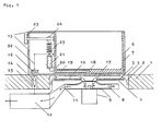
- the kitchen worktop 1 schematically shows an example of a system structure according to the invention.
- the kitchen worktop 1 has a cutout 2 from below, into which the induction coil 3 with the yoke body 4 for the induction field is inserted on a common carrier, not shown.
- the milling 2 is completed at the top by the standing cooking surface 5.
- the cookware 6 consisting of material suitable for inductive heating stands on the cooking surface 5.
- the heat-insulating layer 7 is applied to the bottom and walls of the cookware 6 from the outside. This tableware-friendly cookware, which keeps the food warm for a long time and no longer scratches the surface, can be touched anywhere without being burned.
- the cooling air flow indicated by arrows is drawn in from the center of the induction coil 3 through the closed radial fan wheel 8 of the fan 9.
- the cooling air enters from the periphery into the narrow gap 10 between the induction coil 3 and the underside of the cooking surface 5.
- the blow-out opening 11 of the cooling fan 9 is led to the induction power supply 12, to which the induction coil 3 is connected, so that the components located therein are also cooled by the same fan 9.
- the milling 2 can be carried out such that radially extending ribs (not shown) remain on the underside of the cooking surface 5, which bridge the air gap 10 and are connected or glued to the induction coil 3.
- This firm connection between the cooking surface 5 and the induction coil 3 increases the stability of the cooking surface 5 without the cooling air flow (arrows) being appreciably impaired thereby.
- the ribs even improve the cooling effect.
- the induction power supply 12th can switch on and off.
- the permanent magnet above it in the handle 15 of the cookware 6 16 which, depending on the distance, closes the reed contact 14 or opens.
- the cookware 6 has one for inductive heating suitable floor 17, in a manner known per se for uniformity the temperature is particularly thick (up to approx. 10 mm) is executed.
- the horizontal is in the bottom 17 Bore 18 introduced into which the liquid-filled temperature sensor 19 is inserted over the capillary 20 onto the expansion body 21 acts.
- the permanent magnet 16 is from the expansion body 21 raised above the linkage 22 and actuates the Reed contact 14 as soon as the temperature exceeds the setpoint. This temperature setpoint is set by the rotary knob 23, the preload of the compression spring 25 via the eccentric disk 24 certainly.
- the entire mechanism is in the side of the cookware 6 attached handle 15 housed, which is also from the heat insulating Layer 7 is coated.
- the temperature cycle control of the achievable with this arrangement Cooked food is particularly sensitive because it is on the underside of the Cookware base 17 generated heat the temperature sensor 19 earlier reached as the cookware.
- a magnetic field measuring device (not shown) is also arranged be the cooking power when lifting the permanent magnet 16 reduced proportionally with increasing distance and when lowering accordingly proportionally increased again.
- the resulting steady Temperature control is unsurpassed accuracy.
- Fig. 2 shows an embodiment of the subject of the invention with conventional heating and plug-in thermostat.
- the cookware 32 On the ceramic hob 31 is the cookware 32 with the cookware base 33, which is designed in the usual way as a relatively thick sandwich construction and has a bore 34 for receiving the cladding tube 35 of the plug-in thermostat.
- the cladding tube 35 is itself designed as a temperature sensor and divided on the inside by a partition wall 36 such that only the front part contains liquid 37 and the capillary 38 already begins inside the cladding tube 35 on the partition wall 36.
- the capillary 38 guides the liquid 37, which expands when the temperature rises, into the expansion box 39, which is supported on the ball 40 and via which lever mechanism 41, which strongly converts the expansion movement of the box 39, raises and lowers the switching magnet 42 in a temperature-dependent manner.
- the target temperature is set on the rotary knob 43.
- the ball 40 is provided with a spring 44 so that it can deflect in the event of an overload.
- the casing tube 35 is rigidly anchored, for example soldered, in the housing 45 of the plug-in thermostat, which can be made watertight to be dishwasher-proof.
- a permanent magnet 46 is attached to its housing 45 on both sides of the cladding tube 35 for detachable mounting of the plug-in thermostat on the cookware 32 and as protection against rotation.
- Underneath is the electric heater 47 of the hob 31 with the reflector 48, which adjusts the cooking power of the heater 47 directs above.
- the heating 47 is switched on and off by the power relay 49 switched off, which is actuated by the reed contacts 50, the are electrically connected in parallel.
- To enlarge the reed contact button three reed contacts 50 are arranged side by side, and you can tell by the roughly scaled figure, that the switching magnet 42 is shifted about 1.5 cm in all directions can be made without its influence on the reed contacts 50 to lose.
- the button can be enlarged as required.
- the three reed contacts 50 are vertically next to each other underneath arranged the hob 31 and designed as a reed relay, i.e. she contain electrical coils 51 through which to influence the Switching behavior can be sent a direct current, the one weak, the magnetic field of the switching magnet 42 opposite Magnetic field generated. This happens periodically through the interval switch operating time relay 52, the contact of which e.g. each closed for 10 sec and open for 15 sec. These time constants are based on the design-related thermal inertia behavior the hob 31 with heater 47 and reflector 48 to coordinate. Each the hob 31 is slower, i.e. the longer the after-heat is effective is, the greater should be those set at interval switch 52 Periods of time.
- the level of the direct current in the coils 51 and thus the strength of the opposing magnetic field can depend on the variable resistor 53 are regulated and must be set so that already with a slight lifting of the switching magnet 42, the reed contacts 50 open, with further removal of the switching magnet 42 from the opposing field alone cannot be closed again.
- the circuit can of course be used in the frame the electronics mostly present in the stove anyway with even less Effort can also be set up without contact.
Description
Die Erfindung betrifft ein Kochsystem, bestehend aus einem Kochfeld und einem Kochgeschirr.The invention relates to a cooking system consisting of a Hob and cookware.
Aufgabe der Erfindung ist es, ein Induktions-Kochsystem zu schaffen, bei dem sichergestellt ist, dass eine temperaturempfindliche Kochfläche (z.B. aus Holz, Kunststoff, Keramik, Schiefer, Marmor oder Granit) keine unzulässig hohen Temperaturen annimmt. Ausserdem soll ein Kochgeschirr zur Verfügung gestellt werden, mit dem auch auf einem erfindungsgemässen Induktionsherd ein temperaturgeregelter Kochvorgang möglich ist.The object of the invention is to provide an induction cooking system create, which ensures that a temperature sensitive Cooking surface (e.g. made of wood, plastic, ceramic, Slate, marble or granite) no impermissibly high temperatures assumes. In addition, cookware should be available be made with the induction cooker according to the invention a temperature-controlled cooking process is possible.
FR-A-2 417 725 offenbart ein Induktions-Kochfeld, bei dem eine Induktionsspule unmittelbar an der Unterseite der Kochfläche angeordnet ist. Zwischen Unterseite der Kochfläche mit der Induktionsspule und den für die Induktionsbeheizung notwendigen Schalt- und Steuerelementen ist ein Spalt vorhanden, in dem ein Kühlluftstrom durch ein Gebläse bewirkt wird.FR-A-2 417 725 discloses a Induction hob, where an induction coil is located directly on the underside of the hob is arranged. Between the underside of the hob with the induction coil and for the induction heating necessary switching and control elements is a gap in which a cooling air flow is caused by a fan.
Bei den am Markt befindlichen Induktions-Kochfeldern bestehen die Kochflächen bisher durchweg aus hochhitzefester und gegen Temperaturunterschiede völlig unempfindlicher Glaskeramik (z. B. "Ceran").The induction hobs on the market exist the cooking surfaces so far consistently of high-temperature resistant and against Temperature differences of completely insensitive glass ceramics (e.g. B. "Ceran").
Da das den Kochgeschirrboden erhitzende Induktionsfeld die Kochfläche durchdringt ohne sie zu erhitzen ist schon vorgeschlagen worden, die Kochfläche aus Kunststoff herzustellen (DE 3817438 A1) und zur Abführung der vom Kochgeschirrboden ausgehenden Rückwärme von unten mittels eines Luftstroms zu kühlen. So kann z.B. eine normale Küchenarbeitsplatte oder die Abtropffläche einer Kunststoff-Küchenspüle gleichzeitig als nahtlos durchgehende Kochfläche dienen.Since the induction field that heats the bottom of the cookware is the cooking surface penetrates without heating it is already suggested been to produce the cooking surface from plastic (DE 3817438 A1) and for the removal of those originating from the bottom of the cookware To cool back heat from below using an air stream. So can e.g. a normal kitchen worktop or drainer a plastic kitchen sink at the same time as seamless Serve cooking surface.
Es hat sich jedoch ergeben, dass bei einigen für Küchenarbeitsplatten und Küchenspülen verwendeten Materialien eine Kühlung von unten allein nicht ausreicht, weil ihre Wärmebeständigkeit bzw. Temperaturwechselfestigkeit bereits in der Grössenordnung von ca. 100 °C nachlässt, während Kochgeschirrböden beim Braten bis zu ca. 250 °C heiss werden können.However, it has been found that for some kitchen countertops and kitchen sinks used cooling materials from the bottom alone is not sufficient because of its heat resistance or temperature change resistance already in the order of magnitude of about 100 ° C decreases, while cookware bottoms when roasting can get hot up to approx. 250 ° C.
Es sind auch Kochgeschirre bekannt, welche mit einer isolierenden Schicht am Boden bzw. an den Wänden bedeckt sind (DE 2453169, A1, DE 2906912 A1). Dadurch wird neben einer Energieeinsparung auch bewirkt, dass die Temperaturübertragung auf die Kochfläche reduziert wird, wodurch insbesondere temperaturempfindliche Kochflächen geschützt werden sollen. Bei diesen bekannten Systemen können jedoch trotzdem Überhitzungen der Kochfläche auftreten, da einerseits eine wirksame Wärmeabführung durch Kühlung der Kochfläche nicht vorgesehen ist, andererseits das Kochgeschirr überhitzt werden kann, da wegen der Isolierschicht eine Temperaturregelung über die Kochfläche nicht möglich ist.Cookware is also known, which has an insulating Layer on the floor or on the walls are covered (DE 2453169, A1, DE 2906912 A1). This will save energy as well also causes the temperature transfer to the hob is reduced, making it particularly temperature-sensitive Cooking surfaces should be protected. With these known However, systems can still overheat the hob occur because, on the one hand, effective heat dissipation Cooling the cooking surface is not provided, on the other hand Cookware can be overheated because of the insulating layer temperature control via the cooktop is not possible.
Der erste Teil der Erfindungsaufgabe, eine Überhitzung der temperaturempfindlichen Kochfläche auszuschliessen, wird dadurch gelöst, dass eine wärmeisolierende Schicht zwischen der Oberseite der Kochfläche und dem sich erhitzenden Boden des Kochgeschirrs angeordnet ist, und zwischen Induktionsspule und Unterseite der Kochfläche ein Spalt vorhanden ist, in dem ein Kühlluftstrom durch ein druckstarkes Gebläse bewirkt wird, das unmittelbar mit dem offenen Zentrum der Induktionsspule verbunden ist.The first part of the invention task, overheating the temperature sensitive This excludes the cooking surface solved that a heat insulating layer between the top the cooking surface and the heating base of the cookware is arranged, and between induction coil and bottom there is a gap in the cooktop in which a Cooling air flow is caused by a powerful blower that directly connected to the open center of the induction coil is.
Die Wärmeleitfähigkeit der isolierenden Schicht sollte möglichst geringer sein als die der Kochfläche selbst, sodass der grösste Teil des Wärmegefälles zwischen Kochgeschirrboden und gekühlter Kochflächenunterseite in der wärmeisolierenden Schicht liegt. In einer solchen Anordnung wird die Kochfläche, effektive Kühlung vorausgesetzt, auch beim Braten nur noch handwarm. Darüberhinaus wird Energie eingespart, ein Vorteil, der auch bei induktivem Kochen auf Ceranfeldern genutztwerden kann.The thermal conductivity of the insulating layer should be as possible be smaller than that of the cooking surface itself, so that the largest Part of the heat gradient between the bottom of the cookware and the cooled one Cooking surface underside lies in the heat-insulating layer. In Such an arrangement is the cooking surface, effective cooling provided that they are lukewarm even when roasting. Furthermore energy is saved, an advantage that also with inductive cooking can be used on ceramic hobs.
Die wärmeisolierende Schicht kann auf die Kochflächenoberseite aufgebracht sein. Sie markiert dann gleichzeitig den Kochbereich. Dabei ist vorteilhaft, dass kein spezielles Kochgeschirr benötigt wird. Sie kann aber auch von aussen zumindest auf den Boden, ggf. auch auf die Wände des Kochgeschirrs aufgebracht sein. Dies hat den Vorteil, dass die Kochfläche mit der Küchenarbeitsplatte eine nahtlos durchgehende, glatte Oberfläche bildet, wobei der Kochbereich durch Farbmarkierung, Sandstrahlen, kleine Distanznoppen o.dergl. gekennzeichnet werden kann. Ein solches beschichtetes Kochgeschirr ist auch besonders tischfreundlich. Die Wärmeübertragung auf die Tischplatte ist stark reduziert, Verkratzungen sind ausgeschlossen. Man kann überall anfassen, ohne sich zu verbrennen.The heat-insulating layer can be on the top of the hob be upset. It then marks the cooking area at the same time. It is advantageous that no special cookware is required becomes. But you can also at least on the ground from the outside, if necessary also be applied to the walls of the cookware. This has the Advantage that the cooking surface is seamless with the kitchen worktop continuous, smooth surface forms, the cooking area through color marking, sandblasting, small spacer knobs or the like. can be marked. Such a coated cookware is also particularly table-friendly. The heat transfer to the Table top is greatly reduced, scratches are excluded. You can touch anywhere without getting burned.
Wichtig ist, dass der Spalt zwischen Induktionsspule und Unterseite der Kochfläche, der aus Gründen der Induktionsübertragung nur wenige Millimeter betragen darf, wirksam gekühlt wird. Nur sehr druckstarke Gebläse können ausreichende Luftmengen durch diesen Kühlspalt treiben. Infrage kommen insbesondere Radialgebläse mit geschlossenem Lüfterrad, die zumindest mehrere Zentimeter Wassersäule als Druck aufbauen können. Dabei wird das Gebläse unmittelbar mit dem offenen Zentrum der Induktionsspule verbunden, und zwar vorzugsweise mit seiner Ansaugöffnung. So wird erreicht, dass im Spulenzentrum angesaugte Luft gleichmässig radial vom äusseren Spulenumfang her durch den Kühlspalt zum Zentrum strömt, sodass der Aussenumfang der Kochfläche mit Luft von Raumtemperatur gekühlt wird, die dann zum Zentrum hin immer wärmer wird. Dies dient der Verminderung von Wärmespannungen zwischen der ringsum auf Raumtemperatur befindlichen Küchenarbeitsplatte und dem zum Zentrum hin stetig wärmer werdenden Kochflächenbereich. Gleichzeitig weist die saugseitige Anordnung der Kühlung den Vorteil auf, dass die Kühlluft zuerst die Kochfläche kühlt und dann erst die Verlustwärme des Gebläsemotors abführt, sodass sich an der Kochflächenunterseite die niedrigstmögliche Kühllufttemperatur ergibt. Dabei kann aus Raumspargründen der Antriebsmotor des Kühlgebläses als Aussenläufermotor ausgebildet und in der zentralen Ansaugöffnung des geschlossenen Lüfterrades angeordnet sein.It is important that the gap between the induction coil and the bottom the cooking surface, for reasons of induction transmission can only be a few millimeters, is effectively cooled. Just very powerful blowers can get enough air through this Drive cooling gap. Radial blowers are particularly suitable with closed fan wheel, the at least several centimeters of water can build up as pressure. The blower becomes immediate connected to the open center of the induction coil, and preferably with its suction opening. This ensures that Air sucked into the coil center evenly radially from the outside Coil circumference flows through the cooling gap to the center, so that the The outside of the hob is cooled with air at room temperature which then becomes warmer towards the center. This serves the Reduction of thermal stresses between the all around to room temperature kitchen worktop and towards the center Cooking area is getting warmer. At the same time, the arrangement of the cooling on the suction side has the advantage that the cooling air first the cooking surface cools and then the heat loss of the Blower motor leads away, so that the results in the lowest possible cooling air temperature. It can save space the drive motor of the cooling fan as an external rotor motor trained and closed in the central suction opening of the Fan wheel can be arranged.
Die Ausblasseite des Kühlgebläses kann dann noch in die Stromversorgung für die Induktionsspule geführt werden, sodass dafür kein eigenes Kühlgebläse benötigt wird.The outlet side of the cooling fan can then still be used in the power supply for the induction coil, so that no own cooling fan is required.
Zur mechanischen Verstärkung der Kochfläche, die nur ca. 2-4 mm Stärke aufweist, kann diese auf ihrer Unterseite mit Rippen versehen sein, die radial verlaufen, den Kühlluftspalt von ca. 2-3 mm Stärke überbrücken und mit der Induktionsspule verbunden bzw. verklebt sind.For mechanical reinforcement of the cooking surface, which is only approx. 2-4 mm Starch, it can be provided with ribs on its underside radial, the cooling air gap of approx. 2-3 mm Bridge the thickness and connect or glue it to the induction coil are.
Durch die zwischen Kochflächenoberseite und dem sich erhitzenden Kochgeschirrboden angeordnete wärmeisolierende Schicht sowie die starke Kühlung der Kochfläche von unten wird die Kochflächenunterseite wärmetechnisch weitgehend von der Temperatur des Kochguts entkoppelt, sodass es nicht mehr möglich ist, die Kochguttemperatur durch Abfühlen auf der Kochflächenunterseite thermostatisch feinfühlig zu regeln.Because of the between the top of the hob and the one that heats up Cookware bottom arranged heat insulating layer and the strong cooling of the cooking surface from below becomes the underside of the cooking surface thermally largely from the temperature of the food decoupled, so that it is no longer possible, the food temperature by feeling on the underside of the cooktop thermostatically to regulate sensitively.
Daraus ergibt sich der zweite Teil der Erfindungsaufgabe, dessen Lösung in einer vom Kochgeschirrboden ausgehenden Kochgut-Temperatur-Regelvorrichtung besteht, wobei unter dem Kochfeld mindestens ein magnetisch betätigbarer Kontakt (Reedkontakt) als Schaltstelle für die Leistungszufuhr angeordnet ist, und ein flüssigkeitsgefüllter Temperaturfühler vorgesehen ist, der seitlich am Boden oder in einer horizontalen Bohrung im Boden des Kochgeschirrs angeordnet ist und bei Erhitzung über die eingestellte Temperatur hinaus über einen Ausdehnungskörper einen seitlich am Kochgeschirr angeordneten Permanentmagneten bewegt, z.B. anhebt und so den Kontakt betätigt, der die Kochleistung abschaltet, und der bei Unterschreiten der eingestellten Temperatur den Permanentmagneten wieder zurückbewegt, z.B. absenkt, sodass der Kontakt die Kochleistung wieder einschaltet.This results in the second part of the object of the invention, the Solution in a cookware temperature control device starting from the bottom of the cookware consists, under the hob at least one magnetically operable contact (reed contact) is arranged as a switching point for the power supply, and a liquid-filled temperature sensor is provided, the side of the floor or in a horizontal hole in the Bottom of the cookware is arranged and when heated over the set temperature beyond an expansion body a permanent magnet on the side of the cookware moved, e.g. raises and so operates the contact that the Cooking power switches off, and when the set value is undershot Temperature moved the permanent magnet back again, e.g. lowers so that the contact switches the cooking power on again.
Dieser Teil der Erfindung kann bei allen Kochsystemen angewendet werden, deren Kochflächen für magnetische und / oder elektrische Felder durchlässig sind.This part of the invention can be applied to all cooking systems be, whose cooking surfaces for magnetic and / or electrical Fields are permeable.
Zwar ist schon vorgeschlagen worden (US-Patent 4,617,441), die Kochguttemperatur mit Lichtsignal durch die Kochfläche hindurch zu regeln. Dabei wird jedoch nicht die Temperatur des Kochgeschirrbodens gemessen, sondern ein Spiess als Temperaturfühler in das Kochgut gesteckt, ein Verfahren, das wegen der Nachwärme im Kochgeschirrboden eine geringere Regelgenauigkeit ergibt und auch keinen Trockengehschutz bietet. Ausserdem ist eine besondereVorrichtung zum selbsttätigen Verschliessen der Lichtdurchtrittsöffnung in der Kochfläche bei Fortnahme des optischen Signalgebers und eine eigene Strömversorgung erforderlich, während der Erfindungsgegenstand vollen Trockengehschutz bietet sowie rein mechanisch und auf einer durchgehenden Kochfläche arbeitet. Auch sind schon Heizleistungen für Speisen durch Permanentmagnete und darauf ansprechende Kontakte geschaltet worden (WO 89/04543). Dabei wird jedoch der Permanentmagnet von Hand zu reinen Schaltzwecken bewegt, und nicht, wie bei der Erfindung, durch die Temperatur des Kochgeschirrbodens zum Zweck der Temperaturregelung.The temperature of the food has already been proposed (US Pat. No. 4,617,441) to regulate with a light signal through the cooking surface. However, the temperature of the bottom of the cookware is not measured, but a skewer as a temperature sensor in the food stuck, a process that is due to the residual heat in the cookware bottom a lower control accuracy results and also no dry-running protection offers. In addition, a special device for automatic Closing the light passage opening in the cooking surface if the optical signal transmitter is removed and its own power supply required while the subject of the invention is full Offers dry-run protection as well as purely mechanical and on a continuous basis Cooktop works. There are already heating outputs for Dine with permanent magnets and responsive contacts been switched (WO 89/04543). However, the permanent magnet moved by hand for purely switching purposes and not as in the invention, by the temperature of the bottom of the cookware for the purpose of temperature control.
Aus der DE 3828714 A1 ist es ausserdem bekannt, über ein Bimetall einen Magneten so über einem Reedkontakt zu bewegen, dass die Wärmeleistung in Abhängigkeit von einer vorgegebenen Temperatur ein- und ausgeschaltet wird. From DE 3828714 A1 it is also known to use a bimetal to move a magnet over a reed contact so that the heat output depending on a given temperature is switched on and off.
Der flüssigkeitsgefüllte Ausdehnungskörper bzw. Temperaturfühler kann aussen am Kochgeschirrmantel in Bodennähe bzw. in einer Bodenbohrung angebracht und mit dem Permanentmagneten zu einer baulichen Einheit zusammengefasst sein, sodass ein solches Kochgeschirr mit Temperaturregelung als Einheit, ohne und mit Deckel, voll einsatzfähig ist.The liquid-filled expansion body or temperature sensor can be on the outside of the cookware jacket near the floor or in a floor hole attached and with the permanent magnet to a structural Unit can be summarized so that such cookware with temperature control as a unit, without and with lid, full is operational.
Die Temperaturregelvorrichtung am Kochgeschirr und der Reedkontakt können auch mit umgekehrter Wirkungsweise ausgeführt werden, d.h. so, dass der Permanentmagnet die Kochleistung abschaltet, wenn er der Kochfläche oberhalb des Reedkontaktes angenähert wird. Auch kann anstelle einer Taktregelung eine stetige Regelung vorgesehen werden.The temperature control device on the cookware and the reed contact can also be carried out with the reverse mode of action, i.e. so that the permanent magnet switches off the cooking power when it the cooking surface above the reed contact is approximated. Also a continuous control can be provided instead of a clock control become.
Um das Kochgeschirr herum können unter der Kochfläche mehrere Schaltstellen für verschiedene Leistungsstufen angeordnet sein, sodass die Kochgut-Temperaturregelvorrichtung je nach Drehstellung des Kochgeschirrs auf verschiedene Leistunggstufen der Stromversorgung einwirkt. Durch Einwirkung auf eine niedrigere Leistungsstufe können die Temperatur-Regelschwankungen im Kochgut vermindert werden.Several can be placed around the cookware under the hob Switching points can be arranged for different power levels, so that the food temperature control device depending on the rotary position of the cookware on different power levels of the power supply acts. By acting on a lower power level temperature fluctuations in the food can be reduced become.
In weiterer Ausbildung der Erfindung ist der im wesentlichen aus Temperaturfühler, Schaltmagnet und Temperatureinstellvorrichtung bestehende Thermostat nicht mehr als Griff des Kochgeschirrs, sondern als autonome Daueinheit ausgebildet, sodass er für Kochgeschirre verschiedener Grösse und Art (Töpfe, Kasserolen, Pfannen) verwendet werden kann, und am Kochgeschirr vorzugsweise durch ein am Thermostaten starr befestigtes, den Temperaturfühler enthaltendes Hüllrohr angebracht, das in die etwa bis zur Kochgeschirrmitte reichende oder sogar ganz durchgehende horizontale Bohrung im Kochgeschirrboden eingesteckt werden kann (Steckthermostat). Ferner sind lösbare Befestigungsmittel (Permanentmagnete, Schnappmechanismen, Schraubmechanismen und dergleichen) vorgesehen, die den Steckthermostaten am Kochgeschirr festhalten, wobei die Befestigungmittel so ausgebildet sein können, dass sie derart als Einschaltsperre wirken, dass die temperaturabhängige Lateralbewegung oder Drehbewegung des Schaltmagneten bzw. die Beeinflussung des Reedkontaktes durch den Schaltmagneten nur möglich ist, wenn der Steckthermostat vorschriftsmässig am Kochgeschirr befestigt ist.In a further embodiment of the invention is essentially from Temperature sensor, switching magnet and temperature setting device existing thermostat no longer as a handle of the cookware, but designed as an autonomous permanent unit so that it can be used for cookware various sizes and types (pots, casseroles, pans) can be used, and preferably on the cookware by a rigidly attached to the thermostat and containing the temperature sensor Cladding tube attached that in about to the center of the cookware extensive or even continuous horizontal drilling can be plugged into the bottom of the cookware (plug-in thermostat). Detachable fasteners (permanent magnets, Snap mechanisms, screw mechanisms and the like) are provided, the plug-in thermostats on the cookware hold firmly, the fastening means can be designed so that they act as a switch-on lock so that the temperature-dependent Lateral movement or rotary movement of the switching magnet or the reed contact is only influenced by the switching magnet is possible if the plug-in thermostat is properly connected to the cookware is attached.
In der Praxis hat es sich als vorteilhaft erwiesen, den am Kochgeschirr angebrachten Thermostaten als abnehmbaren Steckthermostaten auszubilden, um die Kochgeschirre zur Aufbewahrung ineinanderstellen sowie in der Geschirrspülmaschine besser unterbringen zu können. Ausserdem kann ein Steckthermostat wechselweise für verschiedene Kochgeschirre verwendet und auch im Falle eines Defelcts leicht ausgetauscht werden. Schliesslich ist so die Benutzung des Kochgeschirrs auch ohne Thermostat möglich.In practice, it has proven to be advantageous to use the cookware attached thermostats as removable plug-in thermostats trained to put the cookware in one another for storage as well as being able to accommodate them better in the dishwasher. In addition, a plug-in thermostat can alternately be used for different Cookware used and easily replaced even in the event of a defect become. After all, that's how the cookware is used also possible without thermostat.
Um einen flüssigkeitsgefüllten Wärmefühler am Steckthermostaten anbringen zu können ist ein starres Hüllrohr erforderlich, in das der Wärmefühler eingeschoben ist, da der an der Kapillare endende aktive Teil des Wärmefühlers aus Gründen der Wärmeankopplung ganz in der Bohrung des Kochgeschirrbodens verschwinden muss. Messungen haben ergeben, dass die durch das im Gehäuse des Steckthermostaten fest verankerte Hüllrohr verursachte Verzögerung des Wärmeübergangs nur geringfügig ist. Soll sie ganz vermieden werden, so kann in weiterer Ausbildung der Erfindung das Hüllrohr selbst als Temperaturfühler ausgebildet, d.h. unmittelbar mit der Flüssigkeit gefüllt und innen derart durch eine Trennwand geteilt sein, dass nur der vordere Teil Flüssigkeit enthält und die Kapillare bereits innerhalb des Hüllrohres an der Trennwand beginnt.To attach a liquid-filled heat sensor to the plug-in thermostat To be able to be a rigid cladding tube is required, in which the The heat sensor is inserted because the end of the capillary active part of the heat sensor for reasons of heat coupling must completely disappear into the hole in the bottom of the cookware. Measurements have shown that the in the housing of the plug-in thermostat firmly anchored cladding tube caused delay the heat transfer is only slight. Should be avoided entirely can be, the cladding tube in a further embodiment of the invention itself designed as a temperature sensor, i.e. immediately with the Liquid filled and divided in this way by a partition be that only the front part contains liquid and the capillary already begins within the cladding tube on the partition.
Der im Hüllrohr angeordnete Temperaturfühler kann auch als Dehnungsstange ausgebildet sein, die den Schaltmagneten temperaturabhängig bewegt und deren Temperaturausdehnungskoeffizient sich von demjenigen des Hüllrohres unterscheidet.The temperature sensor arranged in the cladding tube can also be used as an expansion rod be formed that the switching magnet temperature-dependent moves and their coefficient of thermal expansion is different from that of the cladding tube differs.
Zum Schalten eines Reedkontaktes muss die magnetische Erregung im Reedkontakt verändert werden. Dies kann entweder durch Veränderung der Entfernung des Schaltmagneten zum Reedkontakt (laterale Bewegung) oder durch Verändern des Winkels zwischen der Nord-Süd-Achse des Schaltmagneten und der Achse des Reedkontaktes (Drehbewegung) oder durch eine Kombination beider Bewegungsarten geschehen. Im Falle der Drehbewegung sind Platzbedarf und Energieaufwand zur Bewegung des Schaltmagneten im Steckthermostaten gegenüber der Lateralbewegung etwas reduziert.To switch a reed contact, the magnetic excitation in the Reed contact can be changed. This can be done either through change the distance of the switching magnet to the reed contact (lateral movement) or by changing the angle between the north-south axis of the switching magnet and the axis of the reed contact (rotary movement) or by a combination of both types of movement. in the In the case of the rotary movement, space and energy are required for the movement of the switching magnet in the plug-in thermostat compared to the lateral movement somewhat reduced.
Anstelle des Schaltmagneten kann im Steckthermostaten auch eine ferromagnetische Abschirmung zwischen Schaltmagnet und Reedkontakt temperaturabhängig bewegt werden.Instead of the switching magnet, one can also be inserted in the plug-in thermostat ferromagnetic shielding between switching magnet and reed contact be moved depending on the temperature.
Die Befestigung des Steckthermostaten am Kochgeschirr geschieht, sofern zumindest der Kochgeschirrboden ferromagnetisch ist, am einfachsten und zweckmässigsten durch zwei rechts und links vom Hüllrohr am Gehäuse des Steckthermostaten befestigte Permanentmagnete, die den Steckthermostaten gleichzeitig auch gegen Verdrehen sichern. Bei nicht magnetisierbaren Kochgeschirren müssen andere lösbare Befestigungsmittel wie Schnappmechanismen, Schraubmechanismen und dergleichen eingesetzt werden.The plug-in thermostat is attached to the cookware, as long as the bottom of the cookware is ferromagnetic, the simplest and most conveniently by two to the right and left of the cladding tube permanent magnets attached to the housing of the plug-in thermostat, which also secure the plug-in thermostat against twisting. In the case of non-magnetisable cookware, other detachable ones must Fasteners such as snap mechanisms, screw mechanisms and the like are used.
Um auszuschliessen, dass mit dem Steckthermostaten versehentlich die Kochleistung ohne Kochgeschirr eingeschaltet wird, können die Befestigungsmittel so ausgebildet sein, dass sie, z.B. durch Blockierung der Bewegung des Schaltmagneten, als Einschaltsperre wirken, solange der Steckthermostat nicht vorschriftsmässig am Kochgeschirr befestigt ist. Diese Einschaltsperre wird nicht benötigt, wenn das Kochfeld, wie dies heute vielfach der Fall ist, mit einer Topferkennungsvorrichtung ausgestattet ist, welche die Kochleistung selbsttätig abschaltet, wenn das Kochgeschirr vom Kochfeld entfernt wird.To rule out that accidentally with the plug thermostat the cooking power is switched on without cookware, the Fasteners are designed so that they e.g. by Blocking the movement of the switching magnet, as a switch-on lock act as long as the plug-in thermostat does not comply with the regulations is attached to the cookware. This lockout will not needed when the hob, as is often the case today, is equipped with a pot detection device, which the The cooking power switches off automatically when the cookware is removed from the Cooktop is removed.
Bei der praktischen Handhabung in der Küche muss, um das Funktionieren des Kochsystems zu gewährleisten, darauf geachtet werden, dass der Steckthermostat genügend genau über dem Reedkontakt plaziert wird, dessen Schaltfläche auf auf dem Kochfeld markiert ist. Zur Erleichterung der richtigen Plazierung des Steckthermostaten auf der markierten Reedkontakt-Schaltfläche kann das Kochfeld über dem Reedkontakt zusätzlich mit einem Höcker versehen sein, der in eine entsprechende Aussparung im Boden des Steckthermostaten eingreift. Eine noch bessere, allerdings auch etwas kostenaufwendigere Lösung besteht darin, die Reedkontakt-Schaltfläche durch mehrere, nebeneinander angeordnete, elektrisch parallel geschaltete Reedkontakte zu vergrössern. Dann kommt es auf eine genaue Plazierung des Steckthermostaten nicht mehr an.When it comes to practical handling in the kitchen, it must work of the cooking system, that the plug-in thermostat is placed sufficiently precisely over the reed contact whose button is marked on the hob. For Facilitating the correct placement of the plug-in thermostat the cooktop over the Reed contact must also be provided with a hump that fits into a appropriate recess in the bottom of the plug-in thermostat engages. An even better, but also somewhat more expensive solution consists of pushing the reed contact button through several, side by side arranged, electrically connected reed contacts to enlarge. Then it comes down to an exact placement of the plug-in thermostat no more.
Um eine möglichst genaue Regelung zu erreichen ist zu beachten, dass die Temperatur des Kochguts bzw. des Kochgeschirrbodens auch nach dem Abschalten der Kochleistung noch durch die vom Kochfeld ausgehende Nachwärme beeinflusst wird. Dieser Effekt spielt bei Induktionskochfeldern, bei denen ja die Kochleistung unmittelbar im Kochgeschirrboden erzeugt wird, keine Rolle, kann aber bei Cerankochfeldern mit konventioneller Beheizung durch die Kochfläche hindurch nicht mehr vernachlässigt werden. Hier kommt es darauf an, die Kochleistung schon vor Erreichen der Solltemperatur abzuschalten, sodass die Nachwärme aus dem Kochfeld dann gerade ausreicht, das Kochgut bzw. den Kochgeschirrboden vollends auf Solltemperatur zu bringen. Diese Aufgabe wird in weiterer Ausbildung der Erfindung dadurch gelöst, dass bereits beim ersten Anzeichen einer Bewegung des Schaltmagneten, d.h. bevor er die Position zur Abschaltung der Kochleistung erreicht hat, die Kochleistung abgeschaltet wird. Dies wird durch Ausbildung des Reedkontakts als Reedrelais und durch ein unter dem ICochfeld angeordnetes Zeitschaltglied bewirkt, das als Intervallschalter arbeitet und periodisch eine elektrische Gleichspannung für jeweils eine bestimmte Zeitspanne an die Spule des Reedrelais anlegt, deren Gleichstrom als schwache magnetische Gegenerregung zum Feld des Schaltmagneten auf den Reedkontakt einwirkt, die jedoch allein nicht ausreicht, den Reedkontakt zu betätigen. Sie bewirkt in Verbindung mit dem Feld des Schaltmagneten das Abschalten der Kochleistung, wenn der Schaltmagnet sich auch nur geringfügig aus der Einschaltposition in Richtung Abschaltposition bewegt hat. Wenn dann nach einer bestimmten Zeitspanne der Intervallschalter die Gegenerregung wieder abschaltet, hat der Schaltmagnet sich derart weiterbewegt, dass sein Magnetfeld am Ort des Reedkontakts nicht mehr ausreicht, die Kochleistung wieder einzuschalten. Der Schaltmagnet wird den Reedkontakt erst dann wieder zur Einschaltung der Kochleistung betätigen, wenn der Kochgeschirrboden sich wieder etwas abgekühlt und der Schaltmagnet sich in die Einschaltposition zurückbewegt hat. Mit anderen Worten kann man sagen, dass auf diese Weise die Abschaltposition des Schaltmagneten periodisch näher an die Einschaltposition herangeführt wird, was sich so auswirkt, als wäre die Hysterese des Reedkontaktes periodisch reduziert bzw. als sei die thermische Rückführung des Systems verstärkt, mit dem Ergebnis einer unübertrefflich genauen thermostatischen Regelung der Temperatur des Kochguts bzw. des Kochgeschirrbodens.In order to achieve the most exact possible regulation, please note that the temperature of the food or the bottom of the cookware is too after switching off the cooking power by the hob outgoing heat is affected. This effect plays a role Induction hobs, for which the cooking performance is immediate is generated in the bottom of the cookware, does not matter, but can be used on ceramic with conventional heating through the cooking surface are no longer neglected. Here it depends switch off the cooking output before the set temperature is reached, so that the residual heat from the hob is just sufficient the food or the bottom of the cookware is completely at the set temperature bring to. This object is further developed in the invention solved in that at the first sign of movement of the switching magnet, i.e. before turning off the position the cooking power has reached, the cooking power is switched off. This is done by designing the reed contact as a reed relay and by a timer located under the ICochfeld causes that as Interval switch works and periodically an electrical DC voltage for a certain period of time to the coil of the Reed relays apply their direct current as weak magnetic Counterexcitation to the field of the switching magnet acts on the reed contact, which, however, is not enough to operate the reed contact. It works in connection with the field of the switching magnet switching off the cooking power when the switching magnet is too only slightly from the switch-on position towards the switch-off position has moved. If after a certain period of time the Interval switch switches off the excitation again Switching magnet moves in such a way that its magnetic field is in place of the reed contact is no longer sufficient to switch the cooking power on again. The switching magnet will only become the reed contact again Press to switch on the cooking output when the bottom of the cookware cooled down a bit again and the switching magnet settled into the Has moved the switch-on position back. In other words you can say that in this way the switch-off position of the switching magnet periodically brought closer to the switch-on position, what has the effect that the hysteresis of the reed contact is periodic reduced or as if the thermal feedback of the system reinforced, resulting in an unmatched thermostatic Regulation of the temperature of the food or the bottom of the cookware.
Wenn zur Vergrösserung der Reedkontakt-Schaltfläche mehrere elektrisch parallel geschaltete Reedkontakte nebeneinander angeordnet und als Reedrelais ausgeführt sind, dann müssen die Reedkontakte mit ihrer Achse unbedingt senkrecht zum Kochfeld stehen, sodass jeweils nur eine Anschlussfahne jedes Reedkontakts sich im Wirkungsbereich des Schaltmagneten befindet. Nur dann ist gewährleistet, dass das Feld des Schaltmagneten, unabhängig von seiner Plazierung, in allen Reedkontakten stets in der gleichen Richtung verläuft, und zwar entgegen der Richtung der periodisch angelegten Gleichstromerregung in den Spulen der Reedrelais. If several to enlarge the reed contact button reed contacts connected in parallel arranged side by side and are designed as reed relays, then the reed contacts with their axis absolutely perpendicular to the hob so that only one connecting lug of each reed contact is in the effective range of the switching magnet. Only then is it guaranteed that the field of the switching magnet, regardless of its placement, always runs in the same direction in all reed contacts, and against the direction of the periodically applied DC excitation in the coils of the reed relays.
Die Fig.1 zeigt schematisch ein Beispiel für einen Systemaufbau
nach der Erfindung. Die Küchenarbeitsplatte 1 weist von unten eine
Ausfräsung 2 auf, in welche die Induktionsspule 3 mit dem Rückschlusskörper
4 für das Induktionsfeld auf einem gemeinsamen,
nicht dargestellten Träger eingesetzt ist. Die Ausfräsung 2 wird
nach oben durch die stehengebliebene Kochfläche 5 abgeschlossen.
Auf der Kochfläche 5 steht das aus zur induktiven Erhitzung geeignetem
Material bestehende Kochgeschirr 6. Auf Boden und Wände des
Kochgeschirrs 6 ist von aussen die wärmeisolierende Schicht 7 aufgebracht.
Dieses tischfreundliche Kochgeschirr, das die Speisen
lange warm hält und keine Unterlage mehr verkratzt, kann man aussen
überall anfassen ohne sich zu verbrennen. Der durch Pfeile angedeutete
Kühlluftstrom wird vom Zentrum der Induktionsspule 3 her
durch das geschlossene Radiallüfterrad 8 des Gebläses 9 angesaugt.
Die Kühlluft tritt mit Raumtemperatur von der Peripherie her in den
schmalen Spalt 10 zwischen der Induktionsspule 3 und der Unterseite
der Kochfläche 5 ein. Die Ausblasöffnung 11 des Kühlgebläses 9 ist
zur Indulctions-Stromversorgung 12, an welche die Induktionsspule 3
angeschlossen ist, geführt, sodass die darin befindlichen Bauteile
vom gleichen Gebläse 9 ebenfalls gekühlt werden. Die Ausfräsung 2
kann so ausgeführt werden, dass an der Unterseite der Kochfläche 5
radial verlaufende Rippen (nicht dargestellt) stehen bleiben, die
den Luftspalt 10 überbrücken und mit der Induktionsspule 3 verbunden
bzw. verklebt werden. Durch diesen festen Verbund zwischen
Kochfläche 5 und Induktionsspule 3 wird die Stabilität der Kochfläche
5 erhöht, ohne dass dadurch die Kühlluftströmung (Pfeile)
nennenswert beeinträchtigt wird. Die Kühlwirkung wird durch die
Rippen sogar noch verbessert. 1 schematically shows an example of a system structure according to the invention. The
In ein Sackloch 13 der Küchenarbeitsplatte 1 ist von unten der
Reedkontakt 14 eingesetzt, der die Induktions-Stromversorgung 12
ein- und ausschalten kann. Oberhalb der Küchenarbeitsplatte 1 befindet
sich darüber im Griff 15 des Kochgeschirrs 6 der Permanentmagnet
16, der je nach Abstand den Reedkontakt 14 schliesst oder
öffnet. Das Kochgeschirr 6 weist einen zur induktiven Erhitzung
geeigneten Boden 17 auf, der in an sich bekannter Weise zur Vergleichmässigung
der Temperatur besonders dick (bis zu ca. 10 mm)
ausgeführt ist. In den Boden 17 ist erfindungsgemäss die horizontale
Bohrung 18 eingebracht, in die der flüssigkeitsgefüllte Temperaturfühler
19 eingeschoben ist, der über die Kapillare 20 auf den Ausdehnungskörper
21 einwirkt. Der Permanentmagnet 16 wird von dem Ausdehnungskörper
21 über das Gestänge 22 angehoben und betätigt den
Reedkontakt 14, sobald die Temperatur den Sollwert überschreitet.
Dieser Temperatur-Sollwert wird durch den Drehknopf 23 eingestellt,
der über die Exzenterscheibe 24 die Vorspannung der Druckfeder 25
bestimmt. Die gesamte Mechanik ist in dem seitlich am Kochgeschirr 6
angesetzten Griff 15 untergebracht, der ebenfalls von der wärmeisolierenden
Schicht 7 überzogen ist.In a
Die mit dieser Anordnung erzielbare Temperatur-Taktregelung des
Kochgutes ist besonders feinfühlig, weil die an der Unterseite des
Kochgeschirrbodens 17 erzeugte Wärme den Temperaturfühler 19 früher
erreicht als das Kochgut.The temperature cycle control of the achievable with this arrangement
Cooked food is particularly sensitive because it is on the underside of the
Anstelle des Reedkontaktes 14 kann unter der Küchenarbeitsplatte 1
auch eine (nicht dargestellte) Magnetfeldmesseinrichtung angeordnet
sein, die beim Anheben des Permanetmagneten 16 die Kochleistung
mit zunehmender Distanz proportional reduziert und beim Absenken
entsprechend wieder proportional erhöht. Die sich so ergebende stetige
Temperaturregelung ist von unübertrefflicher Genauigkeit.Instead of the
Die Fig. 2 zeigt ein Ausführungsbeispiel des Erfindungsgegenstandes
mit konventioneller Beheizung und Steckthermostat. Auf dem
Ceranfeld 31 steht das Kochgeschirr 32 mit dem Kochgeschirrboden
33, der in üblicher Weise als relativ dicke Sandwichkonstruktion
ausgeführt ist und eine Bohrung 34 zur Aufnahme des
Hüllrohres 35 des Steckthermostaten aufweist. Das Hüllrohr 35
ist selbst als Temperaturfühler ausgebildet und innen derart
durch eine Trennwand 36 geteilt, dass nur der vordere Teil Flüssigkeit
37 enthält und die Kapillare 38 bereits innerhalb des
Hüllrohres 35 an der Trennwand 36 beginnt. Die Kapillare 38 leitet
die sich bei Temperaturerhöhung ausdehnende Flüssigkeit 37 in die
Ausdehnungsdose 39, die sich an der Kugel 40 abstützt und über den
die Ausdehnungsbewegung der Dose 39 stark übersetzenden Hebelmechanismus
41 den Schaltmagneten 42 temperaturabhängig anhebt und absenkt.
Die Solltemperatur wird an dem Drehknopf 43 eingestellt. Um
eine mechanische Überbeanspruchung der Ausdehnungsdose 39 und des
Hebelmechanismus 41 zu vermeiden, wenn bei heissem Kochgeschirrboden
33 die Solltemperatur an dem Drehlcnopf 43 auf "kalt" gestellt
wird, ist die Kugel 40 mit einer Feder 44 versehen, sodass sie bei
Überlastung ausweichen kann. In dem Gehäuse 45 des Steckthermostaten,
das zur Spülmaschinenfestigkeit wasserdicht ausgeführt sein
kann, ist das Hüllrohr 35 starr verankert, z.B. eingelötet. Zur lösbaren
Halterung des Steckthermostaten am Kochgeschirr 32 und als
Verdrehungsschutz ist an seinem Gehäuse 45 zu beiden Seiten des
Hüllrohres 35 je ein Permanentmagnet 46 befestigt. Fig. 2 shows an embodiment of the subject of the invention with conventional heating and plug-in thermostat. On the
So weit der rein mechanisch arbeitende Teil des Kochsystems nach
der Erfindung, der oberhalb des Ceran-Kochfeldes 31 angeordnet ist.So much for the purely mechanical part of the cooking system
of the invention, which is arranged above the
Darunter befindet sich die elektrische Beheizung 47 des Kochfeldes
31 mit dem Reflektor 48, der die Kochleistung der Beheizung 47 nach
oben lenkt. Die Beheizung 47 wird von dem Leistungsrelais 49 ein-und
aus-geschaltet, das von den Reedkontakten 50 betätigt wird, die
elektrisch parallel geschaltet sind. Zur Vergrösserung der Reedkontakt-Schaltfläche
sind drei Reedkontakte 50 nebeneinander angeordnet,
und man erkennt an der ungefähr masstäblich ausgeführten Figur,
dass der Schaltmagnet 42 nach allen Seiten um ungefähr 1,5 cm verschoben
werden kann, ohne seinen Einfluss auf die Reedkontakte 50
zu verlieren. Die Schaltfläche kann beliebig vergrössert werden.Underneath is the
Die drei Reedkontakte 50 sind senkrecht stehend nebeneinander unter
dem Kochfeld 31 angeordnet und als Reedrelais ausgeführt, d.h. sie
enthalten elektrische Spulen 51, durch die zur Beeinflussung des
Schaltverhaltens ein Gleichstrom geschickt werden kann, der ein
schwaches, dem Magnetfeld des Schaltmagneten 42 entgegengerichtetes
Magnetfeld erzeugt. Das geschieht periodisch durch das als Intervallschalter
arbeitende Zeitrelais 52, dessen Kontakt z.B. jeweils
für 10 sec geschlossen und für 15 sec geöffnet ist. Diese Zeitkonstanten
sind auf das konstruktionsbedingte Wärmeträgheitsverhalten
des Kochfeldes 31 mit Heizung 47 und Reflektor 48 abzustimmen. Je
träger das Kochfeld 31 ist, d.h. je länger die Nachwärme wirksam
ist, umso grösser sollten die am Intervallschalter 52 eingestellten
Zeitspannen sein. Die Höhe des Gleichstroms in den Spulen 51
und damit die Stärke des magnetischen Gegenfeldes kann an dem Stellwiderstand
53 reguliert werden und ist so einzustellen, dass bereits
bei geringfügigem Abheben des Schaltmagneten 42 die Reedkontakte
50 öffnen, bei weiterer Entfernung des Schaltmagneten 42 von
dem Gegenfeld allein aber nicht wieder geschlossen werden können.The three
Anstatt mit Relais kann selbstverständlich die Schaltung im Rahmen der meist im Herd ohnehin vorhandenen Elektronik mit noch geringerem Aufwand auch kontaktlos aufgebaut werden.Instead of using relays, the circuit can of course be used in the frame the electronics mostly present in the stove anyway with even less Effort can also be set up without contact.
Claims (10)
- Cooking system, consisting of an induction cooking hob which has a cooking surface (5) of temperature sensitive material, preferably of wood, plastic, ceramic, slate, marble or granite and which is cooled from below, as well as a cooking pot (6), suitable for inductive heating, which is characterised by a thermally insulating layer (7) arranged between the upper side of the cooking surface (5) and the heated bottom of the cooking pot (6), and a gap (10), present between the induction coil (3) and the lower side of the cooking surface (5), in which a cooling air flow is caused by a blower (8, 9) producing a strong pressure and joined directly with the open centre of the induction coil (3), whereby the blower (8, 9) is preferably joined with its suction aperture to the open centre of the induction coil (3).
- Cooking system according to Claim 1, characterised in that the outlet end (11) of the blower (8, 9) is passed into the power supply (12) for the induction coil (3) and the cooking surface (5) provided with ribs on its lower side which are arranged radially and joined to the induction coil (3).
- Cooking system according to Claims 1-2, characterised in that at least one magnetically operated contact (14) (reed contact) is arranged as switching point for a power feed and a temperature probe (19) is provided under the cooking surface, which is arranged at the side on the bottom or in a horizontal hole (18) in the bottom of the cooking pot (6) and on heating beyond a set temperature moves a permanent magnet (16) mounted on the side of the cooking pot via an expansion element (21), so operating the contact (14) which switches off a cooking power feed and which, on undercutting the set temperature, moves the permanent magnet (16) back so that the contact (14) switches on the cooking power.
- Cooking system according to Claim 3, characterised in that the permanent magnet (16) of the cooked food temperature control device acts on various contacts (14) which switch different power stages of the power supply depending on the rotated position of the cooking pot (6).
- Cooking system according to Claim 3, characterised in that a thermostat, mainly consisting of the temperature probe (35), switching magnet (42) and temperature setting device (40, 43), is formed as an autonomous component, so that it can be used for cooking pots of different size and type and is fitted to the cooking pot (32) preferably using a jacket tube (35) rigidly mounted on the thermostat and containing the temperature probe which can be inserted in the horizontal hole (34) in the bottom of the cooking pot (33) reaching approximately to the centre of the cooking pot or which even completely penetrates the bottom, and in that releasable mounting aids are provided which hold the insertion thermostat on the cooking pot (32), whereby the mounting aids can be so formed that they act as a type of switch-on block and the temperature dependent lateral movement or rotational movement of the switching magnet (42) or the influence on the reed contact (50) by the switching magnet (42) is only possible if the insertion thermostat is mounted properly on the cooking pot (32).
- Cooking system according to Claim 5, characterised by a jacket tube (35) which itself forms the temperature probe and is divided internally by a partition (36) such that only the front part contains liquid (37) and the capillary (38) already begins within the jacket tube (35) at the partition (36).
- Cooking system according to Claim 5, characterised in that the temperature probe arranged inside the jacket tube (35) is formed as an extensible rod which moves the switching magnet (42) depending on the temperature and its temperature expansion coefficient which differs from that of the jacket tube (35).
- Cooking system according to Claim 5, characterised in that instead of the switching magnet (42) being moved in the thermostat, a ferromagnetic screen between the switching magnet (42) and the reed contact (50) is moved depending on the temperature.
- Cooking system according to Claim 5, characterised in that to facilitate the correct positioning of the insertion thermostat on the reed contact switching surfaceeither the cooking hob (31) above the reed contact (50) is provided with a hump which engages in a corresponding recess in the bottom of the insertion thermostat,or the reed contact switching surface is enlarged by a number of adjacently arranged reed contacts (50) electrically connected in parallel.
- Cooking system according to Claim 5, characterised by the formation of the reed contact (50) as a reed relay and a timer (52) arranged under the cooking hob (31) which operates as an interval switch and which periodically applies an electrical direct voltage for a certain time interval to the coil (51) of the reed relay, the direct current of which acts as a weak magnetic counter-excitation to the field of the switching magnet (42) on the reed contact (50) but which is not itself sufficient to operate the reed contact (50).
Applications Claiming Priority (4)
| Application Number | Priority Date | Filing Date | Title |
|---|---|---|---|
| DE4312975A DE4312975C1 (en) | 1993-04-21 | 1993-04-21 | Electric cooking system using inductive heating - has forced cooling air stream between cooking surface and heating coil beneath latter |
| DE4312975 | 1993-04-21 | ||
| DE4410263A DE4410263A1 (en) | 1993-04-21 | 1994-03-24 | Cooking system with cookware |
| DE4410263 | 1994-03-24 |
Publications (3)
| Publication Number | Publication Date |
|---|---|
| EP0621739A2 EP0621739A2 (en) | 1994-10-26 |
| EP0621739A3 EP0621739A3 (en) | 1994-11-30 |
| EP0621739B1 true EP0621739B1 (en) | 1999-11-03 |
Family
ID=25925110
Family Applications (1)
| Application Number | Title | Priority Date | Filing Date |
|---|---|---|---|
| EP19940105554 Expired - Lifetime EP0621739B1 (en) | 1993-04-21 | 1994-04-11 | Cooking system |
Country Status (2)
| Country | Link |
|---|---|
| EP (1) | EP0621739B1 (en) |
| ES (1) | ES2141175T3 (en) |
Cited By (1)
| Publication number | Priority date | Publication date | Assignee | Title |
|---|---|---|---|---|
| CN105144535A (en) * | 2013-07-17 | 2015-12-09 | 皇家飞利浦有限公司 | Wireless inductive power transfer with temperature control of the receiver |
Families Citing this family (6)
| Publication number | Priority date | Publication date | Assignee | Title |
|---|---|---|---|---|
| DE19604436A1 (en) * | 1996-02-07 | 1997-08-14 | Bosch Siemens Hausgeraete | Inductor for installation in trough-like plate for heater in domestic equipment |
| DE19754851A1 (en) | 1997-12-10 | 1999-06-17 | Herchenbach Wolfgang | Cooking system |
| DE102005030164B3 (en) * | 2005-06-29 | 2006-08-10 | Herchenbach, Wolfgang, Dr. | Cooking system, has stove top and cookware that are operated as thermostat, and magnet operated on magnetic field sensor that is formed under cooking surface in top, where thermostat is completely arranged inside sandwich base |
| DE102009043246B3 (en) * | 2009-09-28 | 2011-05-05 | Herchenbach, Wolfgang, Dr. | cooking system |
| DE102011000278A1 (en) * | 2011-01-21 | 2012-07-26 | DESIGNquadrat GbR (vertretungsberechtigte Gesellschafter Alexander Christ, 50679 Köln, Guido Endert, 42799 Leichlingen, Horst Wergen, 42105 Wuppertal) | induction cooker |
| ES2633612B1 (en) * | 2016-03-21 | 2018-07-04 | Bsh Electrodomésticos España, S.A. | Cooking Field Device |
Family Cites Families (12)
| Publication number | Priority date | Publication date | Assignee | Title |
|---|---|---|---|---|
| US3384195A (en) * | 1955-04-15 | 1968-05-21 | Sunbeam Corp | Electric frying pan |
| DE1920778A1 (en) * | 1969-04-24 | 1970-12-17 | Licentia Gmbh | Remote adjustable temperature controller |
| DE2306037A1 (en) * | 1973-02-08 | 1974-08-15 | Environment One Corp | ELECTRIC COOKER |
| GB2010054A (en) * | 1977-08-12 | 1979-06-20 | Ti Group Services Ltd | Electric cooker |
| DE2806794C2 (en) * | 1978-02-17 | 1984-10-25 | Bosch-Siemens Hausgeräte GmbH, 7000 Stuttgart | Stove |
| DE2906912A1 (en) | 1979-02-22 | 1980-09-04 | Sachs Systemtechnik Gmbh | COOKING VESSEL FOR AN INDUCTION COOKER |
| US4617441A (en) | 1983-07-08 | 1986-10-14 | Sanyo Electric Co., Ltd. | Temperature controlled induction heating and cooking apparatus |
| FR2588711A1 (en) * | 1985-10-11 | 1987-04-17 | Cableco Sa | Plate for induction-heated cooking hob and cooking pan usable with such a hob |
| JPS6472490A (en) * | 1987-09-11 | 1989-03-17 | Toshiba Corp | Table with electromagnetic cooker |
| GB8725737D0 (en) | 1987-11-03 | 1987-12-09 | Electrolux Ab | Control apparatus |
| DE3817438A1 (en) | 1988-05-21 | 1989-11-30 | Schock & Co Gmbh | Induction hob (cooking area) |
| DE3828714A1 (en) | 1988-08-24 | 1990-04-26 | Rudi Redmer | Device for heating food and/or drinks |
-
1994
- 1994-04-11 ES ES94105554T patent/ES2141175T3/en not_active Expired - Lifetime
- 1994-04-11 EP EP19940105554 patent/EP0621739B1/en not_active Expired - Lifetime
Cited By (2)
| Publication number | Priority date | Publication date | Assignee | Title |
|---|---|---|---|---|
| CN105144535A (en) * | 2013-07-17 | 2015-12-09 | 皇家飞利浦有限公司 | Wireless inductive power transfer with temperature control of the receiver |
| CN105144535B (en) * | 2013-07-17 | 2017-07-11 | 皇家飞利浦有限公司 | Wireless power induction system and its power receiver and operating method |
Also Published As
| Publication number | Publication date |
|---|---|
| ES2141175T3 (en) | 2000-03-16 |
| EP0621739A3 (en) | 1994-11-30 |
| EP0621739A2 (en) | 1994-10-26 |
Similar Documents
| Publication | Publication Date | Title |
|---|---|---|
| EP3196175B1 (en) | Glass ceramic cooktop with an infrared sensor | |
| US4778978A (en) | Cooking unit with radiant heaters | |
| EP0637898B1 (en) | Working and cooking surface | |
| DE4004129A1 (en) | DEVICE FOR RECOGNIZING A COOKING VESSEL SET UP IN A HEATING ZONE OF A COOKING OR HEATING APPLIANCE | |
| EP0853444A2 (en) | Cooking system with an electric cooking-plate, transferring heat by conduction | |
| DE4312975C1 (en) | Electric cooking system using inductive heating - has forced cooling air stream between cooking surface and heating coil beneath latter | |
| EP0621739B1 (en) | Cooking system | |
| CH654397A5 (en) | ELECTRIC COOKER. | |
| DE4130337A1 (en) | ELECTRIC HEATING UNIT | |
| EP1715316B1 (en) | Measuring sensor system | |
| DD141330A5 (en) | BOWL DEVICE FOR INDUSTRIAL USE AND ASSOCIATED BUCKETS | |
| DE3117205A1 (en) | Optoelectronic cooking panel controller | |
| EP1421326A1 (en) | Domestic appliance | |
| DE3739943A1 (en) | THERMAL PROTECTIVE ARRANGEMENT FOR A COOKER WITH A SOLID GLASS PANEL | |
| CH695817A5 (en) | Rotisserie. | |
| EP0922424B1 (en) | Cooking system | |
| EP1255420A2 (en) | Display device | |
| EP1458003B1 (en) | Temperature sensor | |
| DE10242099B4 (en) | hob | |
| CN210511793U (en) | Integrated kitchen controlling means | |
| DD251496A5 (en) | cooking pot | |
| EP1108385A1 (en) | Water-heating device | |
| EP2237640B1 (en) | Heating drawer | |
| DE3144631A1 (en) | Electrical hotplate | |
| DE202022104469U1 (en) | conditioning apparatus |
Legal Events
| Date | Code | Title | Description |
|---|---|---|---|
| PUAI | Public reference made under article 153(3) epc to a published international application that has entered the european phase |
Free format text: ORIGINAL CODE: 0009012 |
|
| PUAL | Search report despatched |
Free format text: ORIGINAL CODE: 0009013 |
|
| AK | Designated contracting states |
Kind code of ref document: A2 Designated state(s): BE DE ES FR GB IT NL SE |
|
| AK | Designated contracting states |
Kind code of ref document: A3 Designated state(s): BE DE ES FR GB IT NL SE |
|
| 17P | Request for examination filed |
Effective date: 19950519 |
|
| GRAG | Despatch of communication of intention to grant |
Free format text: ORIGINAL CODE: EPIDOS AGRA |
|
| GRAG | Despatch of communication of intention to grant |
Free format text: ORIGINAL CODE: EPIDOS AGRA |
|
| GRAG | Despatch of communication of intention to grant |
Free format text: ORIGINAL CODE: EPIDOS AGRA |
|
| GRAH | Despatch of communication of intention to grant a patent |
Free format text: ORIGINAL CODE: EPIDOS IGRA |
|
| 17Q | First examination report despatched |
Effective date: 19990406 |
|
| GRAH | Despatch of communication of intention to grant a patent |
Free format text: ORIGINAL CODE: EPIDOS IGRA |
|
| GRAA | (expected) grant |
Free format text: ORIGINAL CODE: 0009210 |
|
| AK | Designated contracting states |
Kind code of ref document: B1 Designated state(s): BE DE ES FR GB IT NL SE |
|
| REF | Corresponds to: |
Ref document number: 59408869 Country of ref document: DE Date of ref document: 19991209 |
|
| ITF | It: translation for a ep patent filed |
Owner name: CON LOR S.R.L. |
|
| ET | Fr: translation filed | ||
| GBT | Gb: translation of ep patent filed (gb section 77(6)(a)/1977) |
Effective date: 20000202 |
|
| REG | Reference to a national code |
Ref country code: ES Ref legal event code: FG2A Ref document number: 2141175 Country of ref document: ES Kind code of ref document: T3 |
|
| PLBE | No opposition filed within time limit |
Free format text: ORIGINAL CODE: 0009261 |
|
| STAA | Information on the status of an ep patent application or granted ep patent |
Free format text: STATUS: NO OPPOSITION FILED WITHIN TIME LIMIT |
|
| 26N | No opposition filed | ||
| REG | Reference to a national code |
Ref country code: GB Ref legal event code: IF02 |
|
| PGFP | Annual fee paid to national office [announced via postgrant information from national office to epo] |
Ref country code: GB Payment date: 20050407 Year of fee payment: 12 |
|
| PGFP | Annual fee paid to national office [announced via postgrant information from national office to epo] |
Ref country code: NL Payment date: 20050418 Year of fee payment: 12 |
|
| PGFP | Annual fee paid to national office [announced via postgrant information from national office to epo] |
Ref country code: FR Payment date: 20050419 Year of fee payment: 12 |
|
| PGFP | Annual fee paid to national office [announced via postgrant information from national office to epo] |
Ref country code: ES Payment date: 20050421 Year of fee payment: 12 Ref country code: BE Payment date: 20050421 Year of fee payment: 12 |
|
| PGFP | Annual fee paid to national office [announced via postgrant information from national office to epo] |
Ref country code: SE Payment date: 20050422 Year of fee payment: 12 |
|
| PG25 | Lapsed in a contracting state [announced via postgrant information from national office to epo] |
Ref country code: GB Free format text: LAPSE BECAUSE OF NON-PAYMENT OF DUE FEES Effective date: 20060411 |
|
| PG25 | Lapsed in a contracting state [announced via postgrant information from national office to epo] |
Ref country code: SE Free format text: LAPSE BECAUSE OF NON-PAYMENT OF DUE FEES Effective date: 20060412 Ref country code: ES Free format text: LAPSE BECAUSE OF NON-PAYMENT OF DUE FEES Effective date: 20060412 |
|
| PG25 | Lapsed in a contracting state [announced via postgrant information from national office to epo] |
Ref country code: BE Free format text: LAPSE BECAUSE OF NON-PAYMENT OF DUE FEES Effective date: 20060430 |
|
| PGFP | Annual fee paid to national office [announced via postgrant information from national office to epo] |
Ref country code: IT Payment date: 20060430 Year of fee payment: 13 |
|
| PG25 | Lapsed in a contracting state [announced via postgrant information from national office to epo] |
Ref country code: NL Free format text: LAPSE BECAUSE OF NON-PAYMENT OF DUE FEES Effective date: 20061101 |
|
| EUG | Se: european patent has lapsed | ||
| GBPC | Gb: european patent ceased through non-payment of renewal fee |
Effective date: 20060411 |
|
| NLV4 | Nl: lapsed or anulled due to non-payment of the annual fee |
Effective date: 20061101 |
|
| REG | Reference to a national code |
Ref country code: FR Ref legal event code: ST Effective date: 20061230 |
|
| PGFP | Annual fee paid to national office [announced via postgrant information from national office to epo] |
Ref country code: DE Payment date: 20070531 Year of fee payment: 14 |
|
| REG | Reference to a national code |
Ref country code: ES Ref legal event code: FD2A Effective date: 20060412 |
|
| BERE | Be: lapsed |
Owner name: *HERCHENBACH WOLFGANG Effective date: 20060430 |
|
| PG25 | Lapsed in a contracting state [announced via postgrant information from national office to epo] |
Ref country code: FR Free format text: LAPSE BECAUSE OF NON-PAYMENT OF DUE FEES Effective date: 20060502 |
|
| PG25 | Lapsed in a contracting state [announced via postgrant information from national office to epo] |
Ref country code: DE Free format text: LAPSE BECAUSE OF NON-PAYMENT OF DUE FEES Effective date: 20081101 |
|
| PG25 | Lapsed in a contracting state [announced via postgrant information from national office to epo] |
Ref country code: IT Free format text: LAPSE BECAUSE OF NON-PAYMENT OF DUE FEES Effective date: 20070411 |