EP1715316B1 - Measuring sensor system - Google Patents
Measuring sensor system Download PDFInfo
- Publication number
- EP1715316B1 EP1715316B1 EP06450039A EP06450039A EP1715316B1 EP 1715316 B1 EP1715316 B1 EP 1715316B1 EP 06450039 A EP06450039 A EP 06450039A EP 06450039 A EP06450039 A EP 06450039A EP 1715316 B1 EP1715316 B1 EP 1715316B1
- Authority
- EP
- European Patent Office
- Prior art keywords
- measuring sensor
- resistance path
- arrangement according
- temperature
- sensor
- Prior art date
- Legal status (The legal status is an assumption and is not a legal conclusion. Google has not performed a legal analysis and makes no representation as to the accuracy of the status listed.)
- Expired - Lifetime
Links
Images


Classifications
-
- D—TEXTILES; PAPER
- D06—TREATMENT OF TEXTILES OR THE LIKE; LAUNDERING; FLEXIBLE MATERIALS NOT OTHERWISE PROVIDED FOR
- D06M—TREATMENT, NOT PROVIDED FOR ELSEWHERE IN CLASS D06, OF FIBRES, THREADS, YARNS, FABRICS, FEATHERS OR FIBROUS GOODS MADE FROM SUCH MATERIALS
- D06M15/00—Treating fibres, threads, yarns, fabrics, or fibrous goods made from such materials, with macromolecular compounds; Such treatment combined with mechanical treatment
- D06M15/19—Treating fibres, threads, yarns, fabrics, or fibrous goods made from such materials, with macromolecular compounds; Such treatment combined with mechanical treatment with synthetic macromolecular compounds
- D06M15/21—Macromolecular compounds obtained by reactions only involving carbon-to-carbon unsaturated bonds
- D06M15/356—Macromolecular compounds obtained by reactions only involving carbon-to-carbon unsaturated bonds of other unsaturated compounds containing nitrogen, sulfur, silicon or phosphorus atoms
- D06M15/3562—Macromolecular compounds obtained by reactions only involving carbon-to-carbon unsaturated bonds of other unsaturated compounds containing nitrogen, sulfur, silicon or phosphorus atoms containing nitrogen
-
- G—PHYSICS
- G01—MEASURING; TESTING
- G01K—MEASURING TEMPERATURE; MEASURING QUANTITY OF HEAT; THERMALLY-SENSITIVE ELEMENTS NOT OTHERWISE PROVIDED FOR
- G01K1/00—Details of thermometers not specially adapted for particular types of thermometer
- G01K1/14—Supports; Fastening devices; Arrangements for mounting thermometers in particular locations
-
- H—ELECTRICITY
- H05—ELECTRIC TECHNIQUES NOT OTHERWISE PROVIDED FOR
- H05B—ELECTRIC HEATING; ELECTRIC LIGHT SOURCES NOT OTHERWISE PROVIDED FOR; CIRCUIT ARRANGEMENTS FOR ELECTRIC LIGHT SOURCES, IN GENERAL
- H05B3/00—Ohmic-resistance heating
- H05B3/68—Heating arrangements specially adapted for cooking plates or analogous hot-plates
- H05B3/74—Non-metallic plates, e.g. vitroceramic, ceramic or glassceramic hobs, also including power or control circuits
- H05B3/748—Resistive heating elements, i.e. heating elements exposed to the air, e.g. coil wire heater
-
- D—TEXTILES; PAPER
- D06—TREATMENT OF TEXTILES OR THE LIKE; LAUNDERING; FLEXIBLE MATERIALS NOT OTHERWISE PROVIDED FOR
- D06M—TREATMENT, NOT PROVIDED FOR ELSEWHERE IN CLASS D06, OF FIBRES, THREADS, YARNS, FABRICS, FEATHERS OR FIBROUS GOODS MADE FROM SUCH MATERIALS
- D06M2200/00—Functionality of the treatment composition and/or properties imparted to the textile material
Definitions
- the invention relates to an arrangement comprising a heat source, a heating surface and a sensor arrangement for determining the temperature conditions in the region of a heating surface heated by a heat source, such as e.g. a glass-ceramic heating plate, which is arranged between the heat source and the heating surface substantially parallel to the heating surface
- a heat source such as e.g. a glass-ceramic heating plate
- the sensor arrangement comprises a first sensor comprising a first support body, in particular comprising ceramic, and at least one arranged on the first support body temperature-dependent first resistance path, and the first resistance path of the first sensor faces the heating surface and is electrically contacted outside a temperature-sensitive region at a contacting location
- at least one second measuring sensor being provided, which comprises a second support body, in particular comprising ceramic, and at least one temperature-dependent second resistance path arranged on the second support body includes, which is electrically contacted outside of the temperature-sensitive area at a contact point.
- an electromechanical protective temperature limiter for limiting the maximum temperature are available per heater. If the hob is controlled by electronics, a substitution of the mechanical temperature limiter by electronic temperature sensors is possible because the necessary circuit breakers (relays) are already present. In the electronic control units used, a sensor is often arranged in the field of electronics of an electric range.
- the WO 2004/111589 A1 shows a sensor arrangement for determining the temperature conditions of a heated by a heat source heating surface, such as a glass ceramic hot plate.
- the document shows a first sensor assembly which measures the temperature of the heating surface and a second sensor assembly which measures the temperature of the cavity, or a particular location in the cavity.
- a sensor arrangement for determining the temperature conditions of a heating surface heated by a heat source.
- the first sensor arrangement measures the temperature of the heating surface and the second Probe assembly is provided to measure the temperature of a cooking pot or other cooking utensil.
- the US 5,258,736 A describes the configuration of a temperature sensor and a temperature sensor arrangement.
- This temperature sensor comprises in parallel a temperature-sensitive electrical film resistor and a, also having an electrical resistance, glass ceramic carrier, so that at a predetermined temperature, the sensor measures the temperature by means of the film resistor and measures above this predetermined temperature by means of the exponentially decreasing electrical resistance of the glass ceramic carrier.
- the object of the invention is to provide an arrangement of the type mentioned, which supports the electronic control circuits and supplied with accurate and meaningful for the control of the temperature of a heating surface or for the regulation of heating power temperature data and thereby helps to improve the efficiency of a heating surface or to reduce power consumption.
- the temperatures in the entire boiler room are known. This results in additional safety in the temperature control, such as failure of a sensor or at a faulty control. In addition, this improves the accuracy of the temperature measurement.
- Knowing the temperature of the heat source can be closed before reaching the corresponding temperature at the heating surface on this expected temperature and the regulation of the temperature or the control of the heat source to be adjusted and refined accordingly.
- the desired temperature is achieved more quickly at the heating surface, or substantially saved energy while holding a temperature, since the Schu perennialtemperatur and the heat source temperature can be optimally matched. Since the temperature sensors used are very inexpensive, resulting from the use of two temperature sensors no disadvantage in terms of cost.
- the temperature of the hob surface and the heat source at all times during operation.
- the knowledge of these two temperatures when stored in a suitable arithmetic unit, allows the determination of a temperature characteristic field within the heating unit. This in turn can be used for calibration and self-adjustment of the heating unit.
- the first resistance path and / or the second resistance path have a meandering shape, and are preferably implemented in thick-film technology.
- the most suitable resistance profile for the specific application can be achieved in a simple manner.
- the first measuring sensor and / or the second measuring sensor are designed substantially identical or that the second measuring sensor is designed to be larger than the first measuring sensor.
- the second sensor is larger than the first one, it shades it from the heat of the heat source, making the measurements of the first more accurate.
- the second sensor is designed to absorb radiation. This shadows the first sensor from the heat of the heat source, making the measurements of the first more accurate.
- the first resistance path and / or the second resistance path between the contacting point and the temperature-sensitive area have a larger, in particular double, cross-section than in the temperature-sensitive area. So is the electric Resistance per length of the resistance path in this area significantly reduced and thus kept the influence on the temperature measurement in this area low.
- the measuring sensor arrangement tapers to improve the mechanical stability against the free end facing away from the contacting point.
- sufficient mechanical stability of the support body can be kept as light and material-saving, especially at the end facing away from the contacting shading of the heating coil can be minimized by the support body, or but can be selected large and site-specific dimensioned to the hob or To set the heating surface desired temperature gradient.
- the sensor arrangement has a widened region in the region of the contacting point, wherein the transition to the remaining, narrower region of the sensor arrangement, preferably concave, is rounded.
- the length of the first resistance path and / or the second resistance path in the temperature-sensitive region is at least 200 mm.
- At least one contacting piece of elastically resilient material is provided, which is connected to the support body, preferably riveted.
- the resistance path of the first measuring sensor and / or of the second measuring sensor is insulated with a closed, thermally conductive passivation layer.
- the resistance path is reliably protected against chemical influences and retains its thermoelectric properties for a longer time, so that a temporal drift of the measuring range is minimized.
- rivets can also be covered or covered.
- a holding element is arranged between the first measuring sensor and the second measuring sensor. This can be a defined distance can be maintained.
- a retaining element also serves to isolate the first sensor.
- the holding element is designed as a bracket and / or trough-shaped, wherein preferably in the space spanned by the bracket and / or in the tub an insulating material is arranged.
- a bottom of the trough comprises reinforcing grooves, the cavities formed thereby serving for insulation. This improves the insulation easily and effectively.
- a variant of the invention may consist in that the second sensor is at least partially connected to the holding element, and / or that the holding element has a receptacle for the first sensor.
- the second sensor is at least partially connected to the holding element, and / or that the holding element has a receptacle for the first sensor.
- the first sensor in particular the first support body, in the region of the contact point by means of at least one elastically resilient connecting means, preferably a spring, in particular a metal spring, especially a U-spring or Z-spring with the second sensor and / or the holding element is connected.
- a spring in particular a metal spring, especially a U-spring or Z-spring with the second sensor and / or the holding element is connected.
- the elastically resilient connecting means are thermally stable connected to the first measuring sensor, the second measuring sensor and / or the holding element, in particular by means of screws and / or rivets. In this way it can be ensured that the elastically resilient connecting means are firmly connected in the permanently high temperatures in the space between the heating surface and the heat source.
- the first sensor in the region of the contact point has a stepped reduction, which is lower than the means of the thermally stable connection, wherein when completely arranged in the receptacle of the holding element first sensor, the first resistance path is arranged substantially parallel to the second resistance path.
- the first support body is designed in several parts in the region of the step-shaped lowering. As a result, a particularly simple carrier body can be formed.
- Another possible embodiment may consist in that a substantially angle-shaped retaining clip is provided, which is connected, in particular riveted or screwed, to the second measuring sensor and / or the retaining element. This allows a simple and flexible connection to the environment or the boiler room or the furnace can be created.
- the first resistance path rests flat on the heating surface and / or rests substantially flat and includes a conditional by the heads of the rivets wedge gap. This achieves the most direct possible coupling of the first sensor to the heating surface and the most accurate possible temperature indication.
- a variant of the invention may consist in that the headband has a receptacle, in particular a slide-in receptacle, for the second measuring sensor. This allows the second sensor to be easily picked up and replaced if necessary.
- a, in the use position vertical surface of the retaining clip has a vertically extending slot for mounting and adjustment.
- Fig. 1 to 23 show various embodiments or details of different preferred embodiments of a sensor arrangement for determining the temperature conditions in the region of a heated by a heat source 16 heating surface 15, such as a glass ceramic heating plate, which is arranged between the heat source 16 and the heating surface 15 substantially parallel to the heating surface 15,
- the sensor arrangement comprises a first sensor 1, which comprises a first support body, in particular comprising ceramic, and at least one temperature-dependent first resistance path 23 arranged on the first support body, and the first resistance path 23 of the first sensor 1 faces the heating surface 15 and outside a temperature-sensitive one Area is electrically contacted at a contact point 8, wherein at least one second sensor 2 is provided, which comprises a second support body, in particular comprising ceramic, and at least one disposed on the second support body temperature-dependent second resistance path, which is electrically contacted outside the temperature-sensitive area at a contact point 8, and the second resistance path of the second Sensor of the heat source 16 faces.
- a first measuring sensor 1 is arranged in such a way that, when the measuring sensor arrangement is installed, it comes to lie as flat as possible and directly on the underside of a heating surface 15.
- the use is provided in conjunction with glass ceramic surfaces in kitchen stoves. The preferred dimensions therefore depend on the use in such herds.
- the first resistance path 23 and / or the second resistance path have a meandering shape, and are preferably carried out in thick-film technology.
- Any type of meander shape can be provided. Due to the shape of the meander, the area which is to be resolved particularly sensitively temperature can be determined. It can also be provided no meander.
- thick-film technology which is preferably produced by the screen-printing method, it is also possible to use thin-layer technology or another method.
- first sensor 1 and / or the second sensor 2 are designed substantially identical, resulting in a special savings in terms of parts diversity.
- the second measuring sensor 2 is made larger than the first measuring sensor 1, whereby it shadows the first measuring sensor 1 against the radiant heat of the heat source. This is still positively supported if the second sensor 2 is designed to absorb radiation.
- the temperature measuring range can furthermore be adapted by virtue of the fact that the first resistance path 23 and / or the second resistance path between the contacting point 8 and the temperature-sensitive region have a larger, in particular double, cross section 23a than in the temperature-sensitive region. Larger cross-section means less resistance and lower temperature sensitivity, which may be in demand at the edge.
- the probe assembly against the free, facing away from the contact point 8 end rejuvenate. This is the case in the illustrated preferred embodiments. As a result, only a small part of the heat source 16 is shaded with respect to the heating surface 15. In addition, this effect can be assisted by the fact that the sensor arrangement has a widened region 25 in the region of the contact point 8, wherein the transition to the remaining, narrower region 24 of the sensor arrangement is rounded, preferably concave.
- the temperature sensitivity can be adjusted. Therefore, it may be advantageous for a high temperature sensitivity if the length of the first resistance path 23 and / or the second resistance path in the temperature-sensitive region is at least 200 mm.
- the resistance paths must be permanently electrically contacted under strongly changing thermal conditions. It has proven to be particularly advantageous if at least one contacting piece of elastically resilient material is provided for contacting the first resistance path 23 and / or the second resistance path, which is connected to the support body, preferably riveted.
- the resistance path 23 of the first measuring sensor 1 and / or of the second measuring sensor 2 is insulated with a closed, thermally conductive passivation layer.
- a passivation layer can, if it is made thick enough and any bumps such as screw heads and / or rivets 6, 7 hide or cover and thus contribute to a better flatness, especially the first sensor 1, especially on the heating surface 15.
- a holding element 3, 4 can be arranged between the first measuring sensor 2 and the second measuring sensor 3.
- This holding element 3, 4 can be designed as a bracket and / or trough-shaped, wherein preferably in the space spanned by the bracket and / or in the tub 4, an insulating material is arranged.
- the holding element 3, 4 may be made of any thermally stable material, preferably ceramic or stainless steel.
- the pressing of the first probe 1 to the heating surface 15 is supported in a simple manner by a against the first probe 1 supporting the spring tongue 11, 12 which the second sensor 2 and / or the holding element 3, 4 is arranged. Such an arrangement is approximately in the FIGS. 13 to 17 shown.
- the second sensor 2 is at least partially connected to the holding element 3, 4. This plan is preferably applied to the holding element 3, 4.
- the holding element 3, 4 preferably has the shape of a trapezoidal frame on or a trough 4, wherein the trough 4 may have a trapezoidal or rectangular outline and the bottom and the inside of the trough 4 may preferably be plane-parallel plates.
- the measuring sensors 1, 2 nestle particularly well and advantageously against the holding element 3.
- the holding element 3, 4 preferably has a receptacle for the first measuring sensor 1. This can be provided both in the embodiment as a frame as well as in the tub 4.
- the first measuring sensor 1 rests as flat as possible on the heating surface 15, it can be provided that the first measuring sensor 1, in particular the first supporting body, in the region of the contacting point 8 by means of at least one elastically resilient connecting means, preferably a spring 5, in particular a metal spring, in particular a U-spring or Z-spring, with the second sensor 2 and / or the holding element 3, 4 is connected.
- a spring 5 in particular a metal spring, in particular a U-spring or Z-spring
- thermally stable connecting means are provided, in particular screws and / or rivets 6, 7.
- Rivets to use, as they are permanently solid, thermally stable, cheap and can be mounted automatically.
- the first sensor 1 in the region of the contacting point 8 has a stepped depression, which is lower than the means the thermally stable connection, wherein when completely in the receptacle of the holding member 3, 4 arranged first sensor 1, the first resistance path 23 is arranged substantially parallel to the second resistance path. Due to the stepped reduction, the first sensor 1 can rest flat on the heating surface 15 without this being hindered by the heads of the rivets 6, 7.
- the first support body is designed in several parts in the region of the step-shaped lowering.
- the metrologically important part can be designed as a planner part, which is connected to a further part, and thereby forms a step, such as in the FIGS. 7 and 9 is shown.
- a substantially angle-shaped retaining clip 9 is preferably provided, which is connected, in particular riveted or screwed, to the second measuring sensor 2 and / or the retaining element 3, 4. If the retaining clip 9 is connected to the retaining element 3, 4, it may be provided in particularly preferred embodiments that the retaining clip 9 has a receptacle, in particular a slide-in receptacle, for the second measuring probe 2, whereby a second measuring probe can be applied in a particularly simple manner.
- a vertically extending slot 10 is preferably provided in a vertical position in use position of the retaining clip 9.
Landscapes
- Chemical & Material Sciences (AREA)
- Engineering & Computer Science (AREA)
- Chemical Kinetics & Catalysis (AREA)
- Textile Engineering (AREA)
- Ceramic Engineering (AREA)
- Physics & Mathematics (AREA)
- General Physics & Mathematics (AREA)
- Measuring Temperature Or Quantity Of Heat (AREA)
Description
Die Erfindung betrifft eine Anordnung umfassend eine Wärmequelle, eine Heizfläche und eine Messfühleranordnung zur Ermittlung der Temperaturverhältnisse im Bereich einer von einer Wärmequelle erwärmten Heizfläche, wie z.B. einer Glaskeramik Heizplatte, welche zwischen der Wärmequelle und der Heizfläche im Wesentlichen parallel zur Heizfläche angeordnet ist, wobei die Messfühleranordnung einen ersten Messfühler umfasst, welcher einen ersten Tragkörper, insbesondere umfassend Keramik, und wenigstens eine auf dem ersten Tragkörper angeordnete temperaturabhängige erste Widerstandbahn umfasst, und die erste Widerstandsbahn des ersten Messfühlers der Heizfläche zugewandt ist und außerhalb eines temperatursensitiven Bereichs an einer Kontaktierungsstelle elektrisch kontaktiert ist, wobei wenigstens ein zweiter Messfühler vorgesehen ist, welcher einen zweiten Tragkörper, insbesondere umfassend Keramik, und wenigstens eine auf dem zweiten Tragkörper angeordnete temperaturabhängige zweite Widerstandbahn umfasst, welche außerhalb des temperatursensitiven Bereichs an einer Kontaktierungsstelle elektrisch kontaktiert ist.The invention relates to an arrangement comprising a heat source, a heating surface and a sensor arrangement for determining the temperature conditions in the region of a heating surface heated by a heat source, such as e.g. a glass-ceramic heating plate, which is arranged between the heat source and the heating surface substantially parallel to the heating surface, wherein the sensor arrangement comprises a first sensor comprising a first support body, in particular comprising ceramic, and at least one arranged on the first support body temperature-dependent first resistance path, and the first resistance path of the first sensor faces the heating surface and is electrically contacted outside a temperature-sensitive region at a contacting location, at least one second measuring sensor being provided, which comprises a second support body, in particular comprising ceramic, and at least one temperature-dependent second resistance path arranged on the second support body includes, which is electrically contacted outside of the temperature-sensitive area at a contact point.
Bei üblichen Elektroherden, insbesondere mit Keramikkochfeld, sind pro Heizung ein elektromechanischer Schutztemperaturbegrenzer für die Begrenzung auf die maximale Temperatur vorhanden. Wird das Kochfeld mit einer Elektronik gesteuert, so ist eine Substitution der mechanischen Temperaturbegrenzer durch elektronische Temperaturfühler möglich, da die notwendigen Leistungsschalter (Relais) bereits vorhanden sind. Bei den verwendeten elektronischen Steuereinheiten ist häufig auch im Bereich der Elektronik eines Elektroherdes ein Messfühler angeordnet.In conventional electric cookers, in particular with a ceramic hob, an electromechanical protective temperature limiter for limiting the maximum temperature are available per heater. If the hob is controlled by electronics, a substitution of the mechanical temperature limiter by electronic temperature sensors is possible because the necessary circuit breakers (relays) are already present. In the electronic control units used, a sensor is often arranged in the field of electronics of an electric range.
Bekannte Temperaturfühler liefern lediglich ein unzureichendes Bild der Temperaturverteilung unter der Heizfläche. Dadurch sind die elektronischen Regelkreise nur mit ungenügenden Daten versorgt, was zu nur mangelhaft geregelten Heizflächen führt, wodurch unnötig viel Energie in Wärme umgewandelt wird.Known temperature sensors provide only an insufficient picture of the temperature distribution under the heating surface. As a result, the electronic control circuits are supplied with insufficient data, which leads to poorly controlled heating surfaces, which unnecessarily much energy is converted into heat.
Die
In der
Die
Aufgabe der Erfindung ist es eine Anordnung der eingangs genannten Art anzugeben, welche die elektronischen Regelkreise unterstützt und mit genauen und für die Regelung der Temperatur einer Heizfläche bzw. für die Regelung der Heizleistung sinnvollen Temperaturdaten versorgt und dadurch hilft, den Wirkungsgrad einer Heizfläche zu verbessern bzw. den Stromverbrauch zu senken.The object of the invention is to provide an arrangement of the type mentioned, which supports the electronic control circuits and supplied with accurate and meaningful for the control of the temperature of a heating surface or for the regulation of heating power temperature data and thereby helps to improve the efficiency of a heating surface or to reduce power consumption.
Erfindungsgemäß wird dies dadurch erreicht, dass die zweite Widerstandsbahn des zweiten Messfühlers der Wärmequelle zugewandt ist.According to the invention this is achieved in that the second resistance path of the second sensor facing the heat source.
Dadurch sind die Temperaturen im gesamten Heizraum bekannt. Dadurch ergibt sich eine zusätzliche Sicherheit bei der Temperaturkontrolle, etwa bei Ausfall eines Sensors bzw. bei einer fehlerhaften Ansteuerung. Darüber hinaus wird dadurch die Genauigkeit der Temperaturmessung verbessert. Durch Kenntnis der Temperatur der Wärmequelle kann bereits vor Erreichen der entsprechenden Temperatur an der Heizfläche auf diese zu erwartende Temperatur geschlossen werden und die Regelung der Temperatur bzw. die Regelung der Wärmequelle entsprechend angepasst und verfeinert werden. Dadurch wird schneller die gewünschte Temperatur an der Heizfläche erreicht, bzw. etwa beim Halten einer Temperatur deutlich Energie gespart, da die Heizflächentemperatur und die Wärmequellentemperatur optimal aufeinander abgestimmt werden können. Da die verwendeten Temperatursensoren sehr preiswert sind, entsteht durch die Verwendung von zwei Temperatursensoren kein Nachteil hinsichtlich der Kosten. Für die Betriebssicherheit und Effizienz des Kochfeldes ist es wichtig, im Betrieb zu jedem Zeitpunkt die Temperatur der Kochfeldoberfläche und der Wärmequelle zu kennen. Zusätzlich erlaubt die Kenntnis dieser beiden Temperaturen, wenn in einer geeigneten Recheneinheit abgelegt, die Bestimmung eines Temperaturkennlinienfeldes innerhalb der Heizeinheit. Dies wiederum kann zur Kalibrierung und Selbstjustierung der Heizeinheit genutzt werden.As a result, the temperatures in the entire boiler room are known. This results in additional safety in the temperature control, such as failure of a sensor or at a faulty control. In addition, this improves the accuracy of the temperature measurement. By knowing the temperature of the heat source can be closed before reaching the corresponding temperature at the heating surface on this expected temperature and the regulation of the temperature or the control of the heat source to be adjusted and refined accordingly. As a result, the desired temperature is achieved more quickly at the heating surface, or substantially saved energy while holding a temperature, since the Heizflächentemperatur and the heat source temperature can be optimally matched. Since the temperature sensors used are very inexpensive, resulting from the use of two temperature sensors no disadvantage in terms of cost. For the reliability and efficiency of the hob, it is important to know the temperature of the hob surface and the heat source at all times during operation. In addition, the knowledge of these two temperatures, when stored in a suitable arithmetic unit, allows the determination of a temperature characteristic field within the heating unit. This in turn can be used for calibration and self-adjustment of the heating unit.
In Weiterführung der Erfindung kann vorgesehen sein, dass die erste Widerstandbahn und/oder die zweite Widerstandbahn eine Mäanderform aufweisen, und vorzugsweise in Dickschicht-Technik ausgeführt sind. Dadurch kann auf einfache Weise der für den konkreten Anwendungsfall bestgeeignete Widerstandsverlauf erreicht werden.In a further development of the invention it can be provided that the first resistance path and / or the second resistance path have a meandering shape, and are preferably implemented in thick-film technology. As a result, the most suitable resistance profile for the specific application can be achieved in a simple manner.
In diesem Zusammenhang kann vorgesehen sein, dass der erste Messfühler und/oder der zweite Messfühler im Wesentlichen baugleich ausgeführt sind oder dass der zweite Messfühler größer als der erste Messfühler ausgeführt ist. Dadurch ist eine einfache und kostengünstige Fertigung und Lagerhaltung möglich. Wenn der zweite Messfühler größer als der Erste ist, so schattet er diesen vor der Hitze der Wärmequelle ab, wodurch die Messungen des Ersten genauer werden.In this context, it can be provided that the first measuring sensor and / or the second measuring sensor are designed substantially identical or that the second measuring sensor is designed to be larger than the first measuring sensor. As a result, a simple and cost-effective production and storage is possible. If the second sensor is larger than the first one, it shades it from the heat of the heat source, making the measurements of the first more accurate.
In Weiterführung der Erfindung kann vorgesehen sein, dass der zweite Messfühler strahlungsabsorbierend ausgeführt ist. Dadurch schattet er den ersten Messfühler vor der Hitze der Wärmequelle ab, wodurch die Messungen des Ersten genauer werden.In continuation of the invention can be provided that the second sensor is designed to absorb radiation. This shadows the first sensor from the heat of the heat source, making the measurements of the first more accurate.
In diesem Zusammenhang kann in Weiterführung der Erfindung vorgesehen sein, dass die erste Widerstandbahn und/oder die zweite Widerstandbahn zwischen der Kontaktierungsstelle und dem temperatursensitiven Bereich einen größeren, insbesondere einen doppelten, Querschnitt aufweisen als im temperatursensitiven Bereich. So wird der elektrische Widerstand pro Länge der Widerstandsbahn in diesem Bereich wesentlich herabgesetzt und somit der Einfluss auf die Temperaturmessung in diesem Bereich gering gehalten.In this connection, it can be provided in a further development of the invention that the first resistance path and / or the second resistance path between the contacting point and the temperature-sensitive area have a larger, in particular double, cross-section than in the temperature-sensitive area. So is the electric Resistance per length of the resistance path in this area significantly reduced and thus kept the influence on the temperature measurement in this area low.
Gemäß einer weiteren Ausführungsform der Erfindung kann vorgesehen sein, dass sich die Messfühleranordnung zur Verbesserung der mechanischen Stabilität gegen das freie, von der Kontaktierungsstelle abgekehrte Ende hin verjüngt. So kann bei ausreichender mechanischer Stabilität der Tragkörper möglichst leicht und materialsparend gehalten werden, wobei insbesondere am, von der Kontaktierung abgekehrten Ende die Abschattung der Heizwendel durch den Tragkörper minimal gehalten werden kann, oder aber wählbar groß und ortsspezifisch dimensioniert sein kann, um am Kochfeld bzw. der Heizfläche gewünschte Temperaturgradienten einzustellen.According to a further embodiment of the invention, it can be provided that the measuring sensor arrangement tapers to improve the mechanical stability against the free end facing away from the contacting point. Thus, with sufficient mechanical stability of the support body can be kept as light and material-saving, especially at the end facing away from the contacting shading of the heating coil can be minimized by the support body, or but can be selected large and site-specific dimensioned to the hob or To set the heating surface desired temperature gradient.
In Weiterführung der Erfindung kann vorgesehen sein, dass die Messfühleranordnung im Bereich der Kontaktierungsstelle einen aufgeweiteten Bereich aufweist, wobei der Übergang zum übrigen, schmäleren Bereich der Messfühleranordnung, vorzugsweise konkav, ausgerundet ist. Dadurch kann eine bezogen auf die mechanische Stabilität optimale Materialausnützung erreicht werden.In a further development of the invention it can be provided that the sensor arrangement has a widened region in the region of the contacting point, wherein the transition to the remaining, narrower region of the sensor arrangement, preferably concave, is rounded. As a result, optimum material utilization can be achieved with respect to the mechanical stability.
In diesem Zusammenhang kann in Weiterführung der Erfindung vorgesehen sein, dass die Länge der ersten Widerstandbahn und/oder der zweiten Widerstandbahn im temperatursensitiven Bereich wenigstens 200mm beträgt. Dadurch wird die Temperatur über einen Bereich großer räumlicher Ausdehnung aufgenommen, was der Genauigkeit zugute kommt.In this context, it can be provided in a continuation of the invention that the length of the first resistance path and / or the second resistance path in the temperature-sensitive region is at least 200 mm. As a result, the temperature is recorded over a range of large spatial extent, which benefits the accuracy.
Gemäß einer weiteren Ausführungsform der Erfindung kann vorgesehen sein, dass zur Kontaktierung der ersten Widerstandbahn und/oder der zweiten Widerstandbahn wenigstens ein Kontaktierungsstück aus elastisch federndem Material vorgesehen ist, welches mit dem Tragkörper verbunden, vorzugsweise vernietet ist. So kann eine auch bei oftmaligen Wechseltemperaturbeanspruchungen nachhaltige Kontaktierung hergestellt werden.According to a further embodiment of the invention it can be provided that for contacting the first resistance path and / or the second resistance path at least one contacting piece of elastically resilient material is provided, which is connected to the support body, preferably riveted. Thus, a sustainable contact even with frequent alternating temperature stresses can be produced.
Gemäß wieder einer anderen Ausführungsform der Erfindung kann vorgesehen sein, dass die Widerstandsbahn des ersten Messfühlers und/oder des zweiten Messfühlers mit einer geschlossen, thermisch leitenden Passivierschicht isoliert ist. So wird die Widerstandsbahn zuverlässig vor chemischen Einflüssen geschützt und behält länger ihre thermoelektrischen Eigenschaften, sodass eine zeitliche Drift des Messbereiches minimiert wird. Dadurch können etwa auch Nieten verdeckt bzw. zugedeckt werden.According to yet another embodiment of the invention, it can be provided that the resistance path of the first measuring sensor and / or of the second measuring sensor is insulated with a closed, thermally conductive passivation layer. Thus, the resistance path is reliably protected against chemical influences and retains its thermoelectric properties for a longer time, so that a temporal drift of the measuring range is minimized. As a result, rivets can also be covered or covered.
In weiterer Ausgestaltung der Erfindung kann vorgesehen sein, dass zwischen dem ersten Messfühler und dem zweiten Messfühler ein Halteelement angeordnet ist. Dadurch kann ein definierter Abstand eingehalten werden. Ein Haltelement dient auch der Isolation des ersten Messfühlers.In a further embodiment of the invention it can be provided that a holding element is arranged between the first measuring sensor and the second measuring sensor. This can be a defined distance can be maintained. A retaining element also serves to isolate the first sensor.
In Weiterbildung der Erfindung kann vorgesehen sein, dass das Halteelement als Bügel und/oder wannenförmig ausgeführt ist, wobei vorzugsweise in dem vom Bügel aufgespannten Raum und/oder in der Wanne ein Isoliermaterial angeordnet ist. Dadurch wird ein einfaches und steifes Halteelement geschaffen, welches Platz für Isolationsmaterial aufweist.In a further development of the invention can be provided that the holding element is designed as a bracket and / or trough-shaped, wherein preferably in the space spanned by the bracket and / or in the tub an insulating material is arranged. As a result, a simple and rigid retaining element is created, which has space for insulation material.
Eine andere mögliche Ausführungsform kann darin bestehen, dass ein Boden der Wanne Verstärkungsrillen umfasst, wobei die dadurch gebildeten Hohlräume der Isolation dienen. Dadurch wird die Isolation einfach und wirkungsvoll verbessert.Another possible embodiment may be that a bottom of the trough comprises reinforcing grooves, the cavities formed thereby serving for insulation. This improves the insulation easily and effectively.
Gemäß einer weiteren Ausbildung der Erfindung kann vorgesehen sein, dass an dem zweiten Messfühler und/oder dem Halteelement eine, sich gegen den ersten Messfühler abstützende Federzunge angeordnet ist. Dadurch kann eine genaue Auflage des ersten Messfühlers auf der Heizfläche erreicht werden.According to a further embodiment of the invention, provision may be made for a spring tongue which is supported against the first measuring sensor to be arranged on the second measuring sensor and / or the holding element. As a result, an exact support of the first sensor on the heating surface can be achieved.
Eine Variante der Erfindung kann darin bestehen, dass der zweite Messfühler zumindest bereichsweise mit dem Halteelement verbunden ist, und/oder dass das Halteelement eine Aufnahme für den ersten Messfühler aufweist. Dadurch ist eine exakte Lagerung des zweiten Messfühlers möglich bzw. kann dadurch die Planlage des ersten Messfühlers unterstützt werden. Durch Anordnung in einer Aufnahme kann ein Hohlraum in der Aufnahme geschlossen gehalten werden, wobei die Luft im Hohlraum als Isolator wirkt.A variant of the invention may consist in that the second sensor is at least partially connected to the holding element, and / or that the holding element has a receptacle for the first sensor. As a result, an exact mounting of the second sensor is possible or can be supported by the flatness of the first sensor. By arranging in a receptacle, a cavity in the receptacle can be kept closed, wherein the air acts as an insulator in the cavity.
In weiterer Ausgestaltung der Erfindung kann vorgesehen sein, dass der erste Messfühler, insbesondere der erste Tragkörper, im Bereich der Kontaktierungsstelle mittels wenigstens einem elastisch federnden Verbindungsmittel, vorzugsweise einer Feder, insbesondere einer Metallfeder, vor allem einer U-Feder oder Z-Feder, mit dem zweiten Messfühler und/oder dem Halteelement verbunden ist. Dadurch kann eine genaue Auflage des ersten Messfühlers auf der Heizfläche erreicht werden.In a further embodiment of the invention can be provided that the first sensor, in particular the first support body, in the region of the contact point by means of at least one elastically resilient connecting means, preferably a spring, in particular a metal spring, especially a U-spring or Z-spring with the second sensor and / or the holding element is connected. As a result, an exact support of the first sensor on the heating surface can be achieved.
In Weiterbildung der Erfindung kann vorgesehen sein, dass die elastisch federnden Verbindungsmittel thermisch stabil mit dem ersten Messfühler, dem zweiten Messfühler und/oder dem Halteelement verbunden sind, insbesondere mittels Schrauben und/oder Nieten. Dadurch kann sichergestellt werden, dass such bei den dauerhaft hohen Temperaturen im Raum zwischen Heizfläche und Wärmequelle die elastisch federnden Verbindungsmittel fest verbunden sind.In a development of the invention, it can be provided that the elastically resilient connecting means are thermally stable connected to the first measuring sensor, the second measuring sensor and / or the holding element, in particular by means of screws and / or rivets. In this way it can be ensured that the elastically resilient connecting means are firmly connected in the permanently high temperatures in the space between the heating surface and the heat source.
In weiterer Ausgestaltung der Erfindung kann vorgesehen sein, dass der erste Messfühler im Bereich der Kontaktierungsstelle eine stufenförmige Absenkung aufweist, welche tiefer ist als die Mittel der thermisch stabilen Verbindung, wobei bei vollständig in der Aufnahme des Halteelements angeordnetem ersten Messfühler die erste Widerstandbahn im Wesentlichen parallel zur zweiten Widerstandsbahn angeordnet ist. Dadurch kann auch bei Verwendung von Schrauben oder Nieten eine möglichst plane Auflage des ersten Messfühlers auf der Heizfläche sichergestellt werden, da die Nietenköpfe nicht auf der Heizfläche aufliegen.In a further embodiment of the invention can be provided that the first sensor in the region of the contact point has a stepped reduction, which is lower than the means of the thermally stable connection, wherein when completely arranged in the receptacle of the holding element first sensor, the first resistance path is arranged substantially parallel to the second resistance path. As a result, a possible even support of the first sensor on the heating surface can be ensured even when using screws or rivets, since the rivet heads do not rest on the heating surface.
In Weiterbildung der Erfindung kann vorgesehen sein, dass der erste Tragkörper im Bereich der stufenförmigen Absenkung mehrteilig ausgeführt ist. Dadurch kann ein besonders einfacher Tragkörper gebildet werden.In a further development of the invention it can be provided that the first support body is designed in several parts in the region of the step-shaped lowering. As a result, a particularly simple carrier body can be formed.
Eine andere mögliche Ausführungsform kann darin bestehen, dass ein im Wesentlichen winkelförmiger Haltebügel vorgesehen ist, welcher mit dem zweiten Messfühler und/oder dem Halteelement verbunden, insbesondere vernietet oder verschraubt, ist. Dadurch kann eine einfache und flexible Anbindung an die Umgebung bzw. den Heizraum oder den Ofen geschaffen werden.Another possible embodiment may consist in that a substantially angle-shaped retaining clip is provided, which is connected, in particular riveted or screwed, to the second measuring sensor and / or the retaining element. This allows a simple and flexible connection to the environment or the boiler room or the furnace can be created.
Gemäß einer weiteren Ausbildung der Erfindung kann vorgesehen sein, dass in Betriebslage die erste Widerstandsbahn plan auf der Heizfläche aufliegt und/oder im Wesentlichen plan aufliegt und einen durch die Köpfe der Nieten bedingten Keilspalt einschließt. Dadurch wird eine möglichst direkte Kopplung des ersten Messfühlers mit der Heizfläche erreicht und eine möglichst akkurate Temperaturanzeige.According to a further embodiment of the invention can be provided that in the operating position, the first resistance path rests flat on the heating surface and / or rests substantially flat and includes a conditional by the heads of the rivets wedge gap. This achieves the most direct possible coupling of the first sensor to the heating surface and the most accurate possible temperature indication.
Eine Variante der Erfindung kann darin bestehen, dass der Haltebügel eine Aufnahme, insbesondere eine Einschubaufnahme, für den zweiten Messfühler aufweist. Dadurch kann der zweite Messfühler einfach aufgenommen und gegebenenfalls ausgetauscht werden.A variant of the invention may consist in that the headband has a receptacle, in particular a slide-in receptacle, for the second measuring sensor. This allows the second sensor to be easily picked up and replaced if necessary.
In weiterer Ausgestaltung der Erfindung kann vorgesehen sein, dass eine, in Gebrauchslage vertikale Fläche des Haltebügels ein vertikal verlaufendes Langloch aufweist zur Montage und Justage. Dadurch ist eine einfache Montage und Justage der Messfühleranordnung möglich.In a further embodiment of the invention can be provided that a, in the use position vertical surface of the retaining clip has a vertically extending slot for mounting and adjustment. As a result, a simple assembly and adjustment of the sensor arrangement is possible.
Die Erfindung wird unter Bezugnahme auf die beigeschlossenen Zeichnungen, in welchen besonderes bevorzugte Ausführungsformen dargestellt sind, näher beschrieben. Dabei zeigt:
-
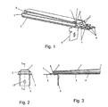
Fig. 1 eine erste Ausführungsform einer erfindungsgemäßen Messfühleranordnung in axonometrischer Darstellung; -
Fig. 2 eine Ausführungsform gemäßFig. 1 im Seitenriss; -
Fig. 3 eine Ausführungsform gemäßFig. 1 im Kreuzriss; -
Fig. 4 eine zweite Ausführungsform einer erfindungsgemäßen Messfühleranordnung in axonometrischer Darstellung; -
Fig. 5 eine Ausführungsform gemäßFig. 4 im Seitenriss; -
Fig. 6 eine Ausführungsform gemäßFig. 4 im Kreuzriss; -
Fig. 7 eine dritte Ausführungsform einer erfindungsgemäßen Messfühleranordnung in axonometrischer Darstellung; -
Fig. 8 eine Ausführungsform gemäßFig. 7 im Seitenriss; -
Fig. 9 eine Ausführungsform gemäßFig. 7 im Kreuzriss; -
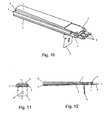
Fig. 10 eine vierte Ausführungsform einer erfindungsgemäßen Messfühleranordnung in axonometrischer Darstellung; -
Fig. 11 eine Ausführungsform gemäßFig. 10 im Seitenriss; -
Fig. 12 eine Ausführungsform gemäßFig. 10 im Kreuzriss; -
Fig. 13 eine fünfte Ausführungsform einer erfindungsgemäßen Messfühleranordnung im Seitenriss; -
Fig. 14 eine Ausführungsform gemäßFig. 13 im Kreuzriss; -
Fig. 15 eine sechste Ausführungsform einer erfindungsgemäßen Messfühleranordnung in axonometrischer Darstellung; -
Fig. 16 eine Ausführungsform gemäßFig. 15 im Seitenriss; -
Fig. 17 eine Ausführungsform gemäßFig. 15 im Kreuzriss; -
Fig. 18 eine weitere Ausführungsform im Kreuzriss; -
Fig. 19 eine Messfühleranordnung mit einer Wärmequelle in axonometrischer Darstellung; -
Fig. 20 eine Anordnung gemäßFig. 19 im Kreuzriss; -
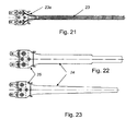
Fig. 21 eine mögliche Ausführungsform eines ersten Messfühlers in Draufsicht; -
Fig. 22 eine weitere Ausführungsform eines ersten Messfühlers in Draufsicht; und -
Fig. 23 eine weitere Ausführungsform eines ersten Messfühlers in Draufsicht;
-
Fig. 1 a first embodiment of a sensor arrangement according to the invention in axonometric representation; -
Fig. 2 an embodiment according toFig. 1 in side elevation; -
Fig. 3 an embodiment according toFig. 1 in the cross order; -
Fig. 4 a second embodiment of a sensor arrangement according to the invention in axonometric representation; -
Fig. 5 an embodiment according toFig. 4 in side elevation; -
Fig. 6 an embodiment according toFig. 4 in the cross order; -
Fig. 7 a third embodiment of a sensor arrangement according to the invention in axonometric representation; -
Fig. 8 an embodiment according toFig. 7 in side elevation; -
Fig. 9 an embodiment according toFig. 7 in the cross order; -
Fig. 10 a fourth embodiment of a sensor arrangement according to the invention in axonometric representation; -
Fig. 11 an embodiment according toFig. 10 in side elevation; -
Fig. 12 an embodiment according toFig. 10 in the cross order; -
Fig. 13 a fifth embodiment of a sensor arrangement according to the invention in side elevation; -
Fig. 14 an embodiment according toFig. 13 in the cross order; -
Fig. 15 a sixth embodiment of a sensor arrangement according to the invention in axonometric representation; -
Fig. 16 an embodiment according toFig. 15 in side elevation; -
Fig. 17 an embodiment according toFig. 15 in the cross order; -
Fig. 18 another embodiment in a cross-sectional view; -
Fig. 19 a sensor arrangement with a heat source in axonometric representation; -
Fig. 20 an arrangement according toFig. 19 in the cross order; -
Fig. 21 a possible embodiment of a first sensor in plan view; -
Fig. 22 a further embodiment of a first sensor in plan view; and -
Fig. 23 a further embodiment of a first sensor in plan view;
Die
Die bevorzugten Ausführungsformen weisen einen zumindest äquivalenten Aufbau auf. Ein erster Messfühler 1 ist derart angeordnet, dass dieser bei eingebauter Messfühleranordnung möglichst plan und direkt auf der Unterseite einer Heizfläche 15 zu liegen kommt. Bevorzugt ist der Einsatz in Verbindung mit Glaskeramikflächen bei Küchenherden vorgesehen. Die bevorzugten Abmessungen richten sich daher nach dem Einsatz bei derartigen Herden.The preferred embodiments have an at least equivalent construction. A
Bei den bevorzugten Ausführungsformen, wie etwa eine in
Es kann vorgesehen sein, dass der erste Messfühler 1 und/oder der zweite Messfühler 2 im Wesentlichen baugleich ausgeführt sind, wodurch sich eine besondere Einsparung hinsichtlich der Teilevielfalt ergibt. Bevorzugt ist allerdings vorgesehen, dass der zweite Messfühler 2 größer als der erste Messfühler 1 ausgeführt ist, wodurch dieser den ersten Messfühler 1 gegen die Strahlungswärme der Wärmequelle abschattet. Dies wird noch positiv unterstützt, wenn der zweite Messfühler 2 strahlungsabsorbierend ausgeführt ist.It can be provided that the
Der Temperaturmessbereich kann weiters dadurch angepasst werden, dass die erste Widerstandbahn 23 und/oder die zweite Widerstandbahn zwischen der Kontaktierungsstelle 8 und dem temperatursensitiven Bereich einen größeren, insbesondere einen doppelten, Querschnitt 23a aufweisen als im temperatursensitiven Bereich. Größerer Querschnitt bedeutet geringerer Widerstand und geringere Temperatursensitivität, was im Randbereich durchaus gefragt sein kann.The temperature measuring range can furthermore be adapted by virtue of the fact that the
Zur Verbesserung der mechanischen Stabilität kann vorgesehen sein, dass sich die Messfühleranordnung gegen das freie, von der Kontaktierungsstelle 8 abgekehrte Ende hin verjüngen. Dies ist bei den dargestellten bevorzugten Ausführungsformen der Fall. Dadurch wird auch nur ein geringer Teil der Wärmequelle 16 gegenüber der Heizfläche 15 abgeschattet. Zusätzlich kann dieser Effekt dadurch unterstützt werden, dass die Messfühleranordnung im Bereich der Kontaktierungsstelle 8 einen aufgeweiteten Bereich 25 aufweist, wobei der Übergang zum übrigen, schmäleren Bereich 24 der Messfühleranordnung, vorzugsweise konkav, ausgerundet ist.To improve the mechanical stability can be provided that the probe assembly against the free, facing away from the
Mittels der Länge der Widerstandsbahnen kann die Temperatursensitivität angepasst werden. Daher kann es für eine hohe Temperatursensitivität vorteilhaft sein, wenn die Länge der ersten Widerstandbahn 23 und/oder der zweiten Widerstandbahn im temperatursensitiven Bereich wenigstens 200mm beträgt.By means of the length of the resistor tracks, the temperature sensitivity can be adjusted. Therefore, it may be advantageous for a high temperature sensitivity if the length of the
Die Widerstandsbahnen müssen dauerhaft unter stark wechselnden thermischen Bedingungen sicher elektrisch kontaktiert werden. Dabei hat es sich als besonders Vorteilhaft erwiesen, wenn zur Kontaktierung der ersten Widerstandbahn 23 und/oder der zweiten Widerstandbahn wenigstens ein Kontaktierungsstück aus elastisch federndem Material vorgesehen ist, welches mit dem Tragkörper verbunden, vorzugsweise vernietet ist.The resistance paths must be permanently electrically contacted under strongly changing thermal conditions. It has proven to be particularly advantageous if at least one contacting piece of elastically resilient material is provided for contacting the
Bei einer besonders bevorzugten Ausführungsform kann vorgesehen sein, dass die Widerstandsbahn 23 des ersten Messfühlers 1 und/oder des zweiten Messfühlers 2 mit einer geschlossen, thermisch leitenden Passivierschicht isoliert ist. Eine derartige Passivierschicht kann, sofern diese dick genug ausgeführt ist auch eventuelle Unebenheiten, wie beispielsweise Schraubenköpfe und/oder Nieten 6, 7 verdecken bzw. verhüllen und dergestalt zu einer besseren Planlage vor allem des ersten Messfühlers 1, vor allem an der Heizfläche 15 beitragen.In a particularly preferred embodiment it can be provided that the
Da der erste Messfühler 1 von der Wärmequelle 16 beeinflusst wird, ist es vorteilhaft diesen gegenüber der Wärmequelle 16 zu isolieren. Daher kann es vorteilhaft sein, dass zwischen dem ersten Messfühler 2 und dem zweiten Messfühler 3 ein Halteelement 3, 4 angeordnet ist. Dieses Halteelement 3, 4 kann als Bügel und/oder wannenförmig ausgeführt sein, wobei vorzugsweise in dem vom Bügel aufgespannten Raum und/oder in der Wanne 4 ein Isoliermaterial angeordnet ist. Das Halteelement 3, 4 kann aus jedem thermisch stabilen Material, vorzugsweise Keramik oder rostfreier Stahl, ausgeführt sein. Durch Verstärkungsrillen 13, welche im Boden der Wanne 4 angeordnet sind, werden Hohlräume 14 gebildet, welche der Isolation dienen, wie in
Das Anpressen des ersten Messfühlers 1 an die Heizfläche 15 wird auf einfache Weise durch eine sich gegen den ersten Messfühler 1 abstützende Federzunge 11, 12 unterstützt, welche an dem zweiten Messfühler 2 und/oder dem Halteelement 3, 4 angeordnet ist. Eine derartige Anordnung ist etwa in den
Der zweite Messfühler 2 ist zumindest bereichsweise mit dem Halteelement 3, 4 verbunden. Vorzugsweise liegt dieser Plan an dem Haltelement 3, 4 an.The
Das Halteelement 3, 4 weist vorzugsweise die Form eines trapezförmigen Rahmens auf oder einer Wanne 4, wobei die Wanne 4 einen trapezförmigen oder rechteckigen Grundriss aufweisen kann und die Unterseite und die Innenseite der Wanne 4 vorzugsweise planparallele Platten sein können. Dadurch schmiegen sich die Messfühler 1, 2 besonders gut und vorteilhaft an das Haltelement 3 an. Bevorzugt weist das Halteelement 3, 4 eine Aufnahme für den ersten Messfühler 1 auf. Dies kann sowohl bei der Ausführung als Rahmen als auch bei der als Wanne 4 vorgesehen sein.The holding
Da es für die Erfindung vorteilhaft ist, wenn der erste Messfühler 1 möglichst plan an der Heizfläche 15 anliegt, kann es vorgesehen sein, dass der erste Messfühler 1, insbesondere der erste Tragkörper, im Bereich der Kontaktierungsstelle 8 mittels wenigstens einem elastisch federnden Verbindungsmittel, vorzugsweise einer Feder 5, insbesondere einer Metallfeder, vor allem einer U-Feder oder Z-Feder, mit dem zweiten Messfühler 2 und/oder dem Halteelement 3, 4 verbunden ist.Since it is advantageous for the invention if the
Um die elastisch federnden Verbindungsmittel sicher und dauerhaft mit dem ersten Messfühler 1, dem zweiten Messfühler 2 und/oder dem Halteelement 3, 4 zu verbinden, sind bevorzugt thermisch stabile Verbindungsmittel vorgesehen, insbesondere Schrauben und/oder Nieten 6, 7. Vor allem ist vorgesehen Nieten zu verwenden, da diese dauerhaft fest sind, thermisch stabil, billig und automatisch montiert werden können.In order to connect the elastically resilient connecting means securely and permanently to the
Bei der Verwendung von Nieten 6, 7 oder auch von Schrauben oder Ähnlichem kann es vorkommen, dass Köpfe von Schrauben und/oder Nieten 6, 7 über die Oberfläche des ersten Messfühlers 1 hinausragen würden und dadurch dessen Planlage verhindern. Es kann bei einer besonders einfachen und kostengünstigen Ausführungsform der Erfindung vorgesehen sein, dies zu akzeptieren. Dabei wird durch die Köpfe der Nieten 6, 7 ein Keilspalt gebildet. Bevorzugt ist allerdings vorgesehen, dass der erste Messfühler 1 möglichst plan auf der Heizfläche 15 aufliegt. Dies kann wie bereits dargelegt durch Beschichten der Oberfläche mit einer thermisch leitenden Passivierschicht erfolgen, wobei die thermisch leitende Passivierschicht auch die Köpfe der Schrauben und Nieten 6, 7 verdeckt. Es kann jedoch anstatt bzw. zusätzlich dazu vorgesehen sein, dass der erste Messfühler 1 im Bereich der Kontaktierungsstelle 8 eine stufenförmige Absenkung aufweist, welche tiefer ist als die Mittel der thermisch stabilen Verbindung, wobei bei vollständig in der Aufnahme des Halteelements 3, 4 angeordnetem ersten Messfühler 1 die erste Widerstandbahn 23 im Wesentlichen parallel zur zweiten Widerstandsbahn angeordnet ist. Durch die stufenförmige Absenkung kann der erste Messfühler 1 plan auf der Heizfläche 15 aufliegen ohne das dies durch die Köpfe der Nieten 6, 7 behindert würde. Um einen ersten Messfühler 1 möglichst einfach aufzubauen, kann es vorgehen sein, dass der erste Tragkörper im Bereich der stufenförmigen Absenkung mehrteilig ausgeführt ist. Dadurch kann der messtechnisch wichtige Teil als planer Teil ausgeführt sein, welcher mit einem weiteren Teil verbunden ist, und dadurch eine Stufe bildet, wie dies etwa in den
Zur Montage und Justage innerhalb einer durch eine Wärmequelle 16 und eine Heizfläche 15 gebildeten Heizraum ist bevorzugt ein im Wesentlichen winkelförmiger Haltebügel 9 vorgesehen, welcher mit dem zweiten Messfühler 2 und/oder dem Halteelement 3, 4 verbunden, insbesondere vernietet oder verschraubt, ist. Sofern der Haltebügel 9 mit dem Halteelement 3, 4 verbunden ist, kann bei besonders bevorzugten Ausführungsformen vorgesehen sein, dass der Haltebügel 9 eine Aufnahme, insbesondere eine Einschubaufnahme, für den zweiten Messfühler 2 aufweist, wodurch ein zweiter Messfühler besonders einfach appliziert werden kann. Zur Montage und Justage, ist vorzugsweise ein vertikal verlaufendes Langloch 10 in einer in Gebrauchslage vertikalen Fläche des Haltebügels 9 vorgesehen.For mounting and adjustment within a heating space formed by a
Claims (15)
- An arrangement, comprising a heat source (16), a heating surface (15) and a measuring sensor arrangement for determining the temperature conditions in the region of the heating surface (15) heated by the beat source (16), with the measuring sensor arrangement being arranged between the heat source (16) and the heating surface (15) substantially parallel to the heating surface (15), with the measuring sensor arrangement comprising a first measuring sensor (1) which comprises a first support body and at least one temperature-dependent first resistance path (23) arranged on the first support body, and the first resistance path (23) of the first measuring sensor (1) faces the heating surface (15) and makes electric contact at a contact point (8) outside of a temperature-sensitive area, with at least one second measuring sensor (2) being provided which comprises a second support body, especially comprising ceramics, and at least one temperature-dependent second resistance path arranged on the second support body, which second resistance path makes electric contact with a contact point (8) outside of the temperature-sensitive area, characterized in that the second resistance path of the second measuring sensor faces the heat source (16).
- An arrangement according to claim 1, characterized in that the first resistance path (23) and/or the second resistance path have a meandering form and are preferably arranged in thick-film technology.
- An arrangement according to claim 1 or 2, characterized in that the first measuring sensor (1) and/or the second measuring sensor (2) are arranged substantially similarly, or the second measuring sensor (2) is arranged to be larger than the first measuring sensor (1).
- An arrangement according to claim 1, 2 or 3, characterized in that the second measuring sensor (2) is arranged to be radiation-absorbing.
- An arrangement according to one of the claims 1 to 4, characterized in that the first resistance path (23) and/or the second resistance path have a larger, especially a double, cross section (23a) between the contact point (8) and the temperature-sensitive area than in the temperature-sensitive area.
- An arrangement according to one of the claims 1 to 5, characterized in that the measuring sensor arrangement tapers towards the free end facing away from the contact point (8) in order to improve mechanical stability.
- An arrangement according to one of the claims 1 to 6, characterized in that at least one contact element made of elastically resilient material is provided for making contact with the first resistance path (23) and/or the second resistance path, which material is connected with the support body, preferably riveted to the same.
- An arrangement according to one of the claims 1 to 7, characterized in that the resistance path (23) of the first measuring sensor (1) and/or second measuring sensor (2) is insulated with a sealed, thermally conductive passivation layer.
- An arrangement according to one of the claims 1 to 8, characterized in that a holding element (3, 4) is arranged between the first measuring sensor (1) and the second measuring sensor (2).
- An arrangement according to claim 9, characterized in that the holding element (3, 4) is arranged as a bracket and/or in a trough-like way, with an insulating material preferably being arranged in the space covered by the bracket and/or in the trough (4).
- An arrangement according to claim 10, characterized in that a floor of the trough (4) comprises reinforcing ribs (13), with the cavities (14) thus formed being used for insulation.
- An arrangement according to claim 9, 10 or 11, characterized in that an elastic tongue (11, 12) resting on the first measuring sensor (1) is arranged on the second measuring sensor (2) and/or the holding element (3, 4).
- An arrangement according to one of the claims 9 to 12, characterized in that the second measuring sensor (2) is connected at least in sections with the holding element (3, 4), and/or that the holding element (3, 4) comprises a receiver for the first measuring sensor (1).
- An arrangement according to one of the claims 9 to 13, characterized in that the first measuring sensor (1), especially the first support body, is connected with the second measuring sensor (2) and/or the holding element (3, 4) in the region of the contact point (8) by means of at least one elastically resilient connecting means, preferably a spring (5), especially a metal spring, in particular a U-spring or Z-spring.
- An arrangement according to one of the claims 9 to 14, characterized in that the first measuring sensor (1) comprises a stepped depression in the region of the contact point (8), which depression is lower than the means of the thermally stable connection, with the first resistance path (23) being arranged substantially parallel to the second resistance path when the first measuring sensor (1) is arranged completely in the receiver of the holding element (3, 4).
Priority Applications (1)
| Application Number | Priority Date | Filing Date | Title |
|---|---|---|---|
| PL06450039T PL1715316T3 (en) | 2005-04-19 | 2006-03-20 | Measuring sensor system |
Applications Claiming Priority (1)
| Application Number | Priority Date | Filing Date | Title |
|---|---|---|---|
| AT0024105U AT8257U1 (en) | 2005-04-19 | 2005-04-19 | SENSOR ARRANGEMENT |
Publications (2)
| Publication Number | Publication Date |
|---|---|
| EP1715316A1 EP1715316A1 (en) | 2006-10-25 |
| EP1715316B1 true EP1715316B1 (en) | 2011-01-05 |
Family
ID=35070933
Family Applications (1)
| Application Number | Title | Priority Date | Filing Date |
|---|---|---|---|
| EP06450039A Expired - Lifetime EP1715316B1 (en) | 2005-04-19 | 2006-03-20 | Measuring sensor system |
Country Status (5)
| Country | Link |
|---|---|
| US (1) | US7534032B2 (en) |
| EP (1) | EP1715316B1 (en) |
| AT (2) | AT8257U1 (en) |
| DE (2) | DE202005011147U1 (en) |
| PL (1) | PL1715316T3 (en) |
Families Citing this family (9)
| Publication number | Priority date | Publication date | Assignee | Title |
|---|---|---|---|---|
| DE102006016956B4 (en) * | 2006-04-11 | 2009-10-08 | Electrolux Home Products Corp. N.V. | A method for determining the heat absorbed by a food in a cooking appliance and cooking appliance for performing the method |
| WO2008117909A1 (en) | 2007-03-28 | 2008-10-02 | Lg Electronics Inc. | Heat detecting device, cooking apparatus using the same and a method of controoling the cooking apparatus |
| CH701673B1 (en) * | 2010-12-13 | 2014-05-15 | V Zug Ag | Cooking appliance with thermal unit. |
| US8702303B2 (en) | 2011-06-29 | 2014-04-22 | Schneider Electric USA, Inc. | Sensor mounting methodology |
| FR3017457A1 (en) * | 2014-02-11 | 2015-08-14 | Turbomeca | DEVICE FOR FIXING A SENSOR ON A PIECE |
| US10018514B2 (en) * | 2014-02-17 | 2018-07-10 | Haier Us Appliance Solutions, Inc. | Cooktop temperature sensors and methods of operation |
| US20160227609A1 (en) * | 2015-01-30 | 2016-08-04 | Schott Corporation | Multi function glass or glass-ceramic cooktop system and method of cooking thereon |
| KR101724499B1 (en) * | 2015-12-11 | 2017-04-07 | 현대자동차 주식회사 | Particulate matter sensor and measurement method thereof |
| CN107889300A (en) * | 2016-09-29 | 2018-04-06 | 浙江久康电器有限公司 | The electrical heating stove of plug-in type infrared ray electric heat stove plate and the dress electric heating furnace tray |
Family Cites Families (12)
| Publication number | Priority date | Publication date | Assignee | Title |
|---|---|---|---|---|
| DE2913866C2 (en) * | 1979-04-06 | 1987-03-12 | Robert Bosch Gmbh, 7000 Stuttgart | Sensor for the determination of components in flowing gases |
| DE3934157C2 (en) | 1989-10-12 | 1999-01-28 | Bosch Siemens Hausgeraete | Hob |
| DE4022845A1 (en) * | 1990-07-18 | 1992-01-23 | Schott Glaswerke | TEMPERATURE SENSOR OR SENSOR ARRANGEMENT MADE OF GLASS CERAMIC AND CONTACTING FILM RESISTORS |
| DE19906115C1 (en) * | 1999-02-13 | 2000-08-31 | Schott Glas | Method for recognizing the empty cooking of dishes in hobs with a glass ceramic hob and associated device |
| US6746586B2 (en) * | 2000-07-31 | 2004-06-08 | Ngk Spark Plug Co., Ltd. | Multi-layer gas sensor element and gas sensor comprising the same |
| US6588253B2 (en) * | 2001-08-17 | 2003-07-08 | Delphi Technologies, Inc. | Fuel volatitlity sensor and method based on capacitance measurement |
| US6634210B1 (en) * | 2002-04-17 | 2003-10-21 | Delphi Technologies, Inc. | Particulate sensor system |
| GB0313703D0 (en) * | 2003-06-13 | 2003-07-16 | Ceramaspeed Ltd | Temperature sensor assembly for an electrical heating arrangement |
| GB0313831D0 (en) * | 2003-06-16 | 2003-07-23 | Ceramaspeed Ltd | Apparatus and method for detecting abnormal temperature rise associated with a cooking arrangement |
| ATE332493T1 (en) * | 2004-02-24 | 2006-07-15 | Electrovac | TEMPERATURE PROBE |
| US7069770B2 (en) * | 2004-08-02 | 2006-07-04 | Delphi Technologies, Inc. | Ammonia sensor element, heater, and method for making the same |
| GB0426467D0 (en) * | 2004-12-02 | 2005-01-05 | Ceramaspeed Ltd | Apparatus for detecting abnormal temperature rise associated with a cooking arrangement |
-
2005
- 2005-04-19 AT AT0024105U patent/AT8257U1/en not_active IP Right Cessation
- 2005-07-15 DE DE202005011147U patent/DE202005011147U1/en not_active Expired - Lifetime
-
2006
- 2006-03-20 AT AT06450039T patent/ATE494533T1/en active
- 2006-03-20 PL PL06450039T patent/PL1715316T3/en unknown
- 2006-03-20 EP EP06450039A patent/EP1715316B1/en not_active Expired - Lifetime
- 2006-03-20 DE DE502006008638T patent/DE502006008638D1/en not_active Expired - Lifetime
- 2006-04-18 US US11/379,108 patent/US7534032B2/en not_active Expired - Fee Related
Also Published As
| Publication number | Publication date |
|---|---|
| DE202005011147U1 (en) | 2005-09-29 |
| AT8257U1 (en) | 2006-04-15 |
| US20060231546A1 (en) | 2006-10-19 |
| PL1715316T3 (en) | 2011-06-30 |
| EP1715316A1 (en) | 2006-10-25 |
| ATE494533T1 (en) | 2011-01-15 |
| US7534032B2 (en) | 2009-05-19 |
| DE502006008638D1 (en) | 2011-02-17 |
Similar Documents
| Publication | Publication Date | Title |
|---|---|---|
| EP1715316B1 (en) | Measuring sensor system | |
| DE4022844C1 (en) | ||
| US6555793B2 (en) | Advanced radiant electric heater | |
| US6940048B2 (en) | Radiant electric heater incorporating a temperature sensor assembly | |
| EP1850101A1 (en) | Temperature sensing probe assembly | |
| DE102016221546B4 (en) | Hob with weighing function | |
| EP1568980B2 (en) | Temperature sensor | |
| US20060237438A1 (en) | Temperature sensor assembly for an electrical heating arrangement | |
| GB0206738D0 (en) | Electrical heating assembly | |
| WO2001062049A1 (en) | Cooking surface comprising a temperature sensor | |
| FI57509C (en) | TEMPERATURBEGRAENSARE | |
| WO2006136363A1 (en) | Sensor device for a heating device | |
| DE602005001501T2 (en) | ELECTRIC HEATING ARRANGEMENT | |
| EP1303169A1 (en) | Temperature sensor with a sensing element and its application | |
| EP2649860B1 (en) | Heating device for a household appliance and household appliance comprising such a heating device | |
| DE212011100126U1 (en) | Improved electronic and electro-mechanical thermostat | |
| EP1857742A2 (en) | Hob with a sensor device | |
| DE102013108646A1 (en) | Cooking device and method for operating a cooking device | |
| EP0621739A2 (en) | Cooking system | |
| DE3033605C2 (en) | Room thermostat | |
| EP2183758A1 (en) | Temperature sensor | |
| US20070062930A1 (en) | Method of controlling boiling level | |
| EP0740895A1 (en) | A device for determining the thermal load of a cooking zone | |
| DE102009015525A1 (en) | Cooking or heating device e.g. induction cooker, for preparation of food in kitchen, has control element comprising user interface together with heating surface of working area formed as single part | |
| DE19646959A1 (en) | Glass ceramic panel for gas-burning cooker |
Legal Events
| Date | Code | Title | Description |
|---|---|---|---|
| PUAI | Public reference made under article 153(3) epc to a published international application that has entered the european phase |
Free format text: ORIGINAL CODE: 0009012 |
|
| AK | Designated contracting states |
Kind code of ref document: A1 Designated state(s): AT BE BG CH CY CZ DE DK EE ES FI FR GB GR HU IE IS IT LI LT LU LV MC NL PL PT RO SE SI SK TR |
|
| AX | Request for extension of the european patent |
Extension state: AL BA HR MK YU |
|
| 17P | Request for examination filed |
Effective date: 20070425 |
|
| 17Q | First examination report despatched |
Effective date: 20070524 |
|
| AKX | Designation fees paid |
Designated state(s): AT BE BG CH CY CZ DE DK EE ES FI FR GB GR HU IE IS IT LI LT LU LV MC NL PL PT RO SE SI SK TR |
|
| RAP1 | Party data changed (applicant data changed or rights of an application transferred) |
Owner name: ELECTROVAC AG |
|
| GRAP | Despatch of communication of intention to grant a patent |
Free format text: ORIGINAL CODE: EPIDOSNIGR1 |
|
| GRAS | Grant fee paid |
Free format text: ORIGINAL CODE: EPIDOSNIGR3 |
|
| GRAA | (expected) grant |
Free format text: ORIGINAL CODE: 0009210 |
|
| AK | Designated contracting states |
Kind code of ref document: B1 Designated state(s): AT BE BG CH CY CZ DE DK EE ES FI FR GB GR HU IE IS IT LI LT LU LV MC NL PL PT RO SE SI SK TR |
|
| REG | Reference to a national code |
Ref country code: GB Ref legal event code: FG4D Free format text: NOT ENGLISH |
|
| REG | Reference to a national code |
Ref country code: CH Ref legal event code: EP |
|
| REG | Reference to a national code |
Ref country code: IE Ref legal event code: FG4D Free format text: LANGUAGE OF EP DOCUMENT: GERMAN |
|
| REF | Corresponds to: |
Ref document number: 502006008638 Country of ref document: DE Date of ref document: 20110217 Kind code of ref document: P |
|
| REG | Reference to a national code |
Ref country code: DE Ref legal event code: R096 Ref document number: 502006008638 Country of ref document: DE Effective date: 20110217 |
|
| REG | Reference to a national code |
Ref country code: NL Ref legal event code: VDEP Effective date: 20110105 |
|
| PG25 | Lapsed in a contracting state [announced via postgrant information from national office to epo] |
Ref country code: SI Free format text: LAPSE BECAUSE OF FAILURE TO SUBMIT A TRANSLATION OF THE DESCRIPTION OR TO PAY THE FEE WITHIN THE PRESCRIBED TIME-LIMIT Effective date: 20110105 |
|
| PGFP | Annual fee paid to national office [announced via postgrant information from national office to epo] |
Ref country code: AT Payment date: 20110331 Year of fee payment: 6 |
|
| REG | Reference to a national code |
Ref country code: FR Ref legal event code: CD |
|
| LTIE | Lt: invalidation of european patent or patent extension |
Effective date: 20110105 |
|
| REG | Reference to a national code |
Ref country code: PL Ref legal event code: T3 |
|
| PG25 | Lapsed in a contracting state [announced via postgrant information from national office to epo] |
Ref country code: IS Free format text: LAPSE BECAUSE OF FAILURE TO SUBMIT A TRANSLATION OF THE DESCRIPTION OR TO PAY THE FEE WITHIN THE PRESCRIBED TIME-LIMIT Effective date: 20110505 Ref country code: PT Free format text: LAPSE BECAUSE OF FAILURE TO SUBMIT A TRANSLATION OF THE DESCRIPTION OR TO PAY THE FEE WITHIN THE PRESCRIBED TIME-LIMIT Effective date: 20110505 Ref country code: LV Free format text: LAPSE BECAUSE OF FAILURE TO SUBMIT A TRANSLATION OF THE DESCRIPTION OR TO PAY THE FEE WITHIN THE PRESCRIBED TIME-LIMIT Effective date: 20110105 Ref country code: GR Free format text: LAPSE BECAUSE OF FAILURE TO SUBMIT A TRANSLATION OF THE DESCRIPTION OR TO PAY THE FEE WITHIN THE PRESCRIBED TIME-LIMIT Effective date: 20110406 Ref country code: SE Free format text: LAPSE BECAUSE OF FAILURE TO SUBMIT A TRANSLATION OF THE DESCRIPTION OR TO PAY THE FEE WITHIN THE PRESCRIBED TIME-LIMIT Effective date: 20110105 Ref country code: LT Free format text: LAPSE BECAUSE OF FAILURE TO SUBMIT A TRANSLATION OF THE DESCRIPTION OR TO PAY THE FEE WITHIN THE PRESCRIBED TIME-LIMIT Effective date: 20110105 Ref country code: ES Free format text: LAPSE BECAUSE OF FAILURE TO SUBMIT A TRANSLATION OF THE DESCRIPTION OR TO PAY THE FEE WITHIN THE PRESCRIBED TIME-LIMIT Effective date: 20110416 |
|
| PGFP | Annual fee paid to national office [announced via postgrant information from national office to epo] |
Ref country code: GB Payment date: 20110331 Year of fee payment: 6 Ref country code: FR Payment date: 20110414 Year of fee payment: 6 |
|
| REG | Reference to a national code |
Ref country code: IE Ref legal event code: FD4D |
|
| PG25 | Lapsed in a contracting state [announced via postgrant information from national office to epo] |
Ref country code: BG Free format text: LAPSE BECAUSE OF FAILURE TO SUBMIT A TRANSLATION OF THE DESCRIPTION OR TO PAY THE FEE WITHIN THE PRESCRIBED TIME-LIMIT Effective date: 20110405 Ref country code: FI Free format text: LAPSE BECAUSE OF FAILURE TO SUBMIT A TRANSLATION OF THE DESCRIPTION OR TO PAY THE FEE WITHIN THE PRESCRIBED TIME-LIMIT Effective date: 20110105 Ref country code: NL Free format text: LAPSE BECAUSE OF FAILURE TO SUBMIT A TRANSLATION OF THE DESCRIPTION OR TO PAY THE FEE WITHIN THE PRESCRIBED TIME-LIMIT Effective date: 20110105 Ref country code: CY Free format text: LAPSE BECAUSE OF FAILURE TO SUBMIT A TRANSLATION OF THE DESCRIPTION OR TO PAY THE FEE WITHIN THE PRESCRIBED TIME-LIMIT Effective date: 20110105 |
|
| PGFP | Annual fee paid to national office [announced via postgrant information from national office to epo] |
Ref country code: PL Payment date: 20110404 Year of fee payment: 6 |
|
| BERE | Be: lapsed |
Owner name: ELECTROVAC AG Effective date: 20110331 |
|
| PGFP | Annual fee paid to national office [announced via postgrant information from national office to epo] |
Ref country code: DE Payment date: 20110526 Year of fee payment: 6 |
|
| PG25 | Lapsed in a contracting state [announced via postgrant information from national office to epo] |
Ref country code: IE Free format text: LAPSE BECAUSE OF FAILURE TO SUBMIT A TRANSLATION OF THE DESCRIPTION OR TO PAY THE FEE WITHIN THE PRESCRIBED TIME-LIMIT Effective date: 20110105 Ref country code: MC Free format text: LAPSE BECAUSE OF NON-PAYMENT OF DUE FEES Effective date: 20110331 Ref country code: DK Free format text: LAPSE BECAUSE OF FAILURE TO SUBMIT A TRANSLATION OF THE DESCRIPTION OR TO PAY THE FEE WITHIN THE PRESCRIBED TIME-LIMIT Effective date: 20110105 Ref country code: EE Free format text: LAPSE BECAUSE OF FAILURE TO SUBMIT A TRANSLATION OF THE DESCRIPTION OR TO PAY THE FEE WITHIN THE PRESCRIBED TIME-LIMIT Effective date: 20110105 |
|
| REG | Reference to a national code |
Ref country code: CH Ref legal event code: PL |
|
| PLBE | No opposition filed within time limit |
Free format text: ORIGINAL CODE: 0009261 |
|
| STAA | Information on the status of an ep patent application or granted ep patent |
Free format text: STATUS: NO OPPOSITION FILED WITHIN TIME LIMIT |
|
| PG25 | Lapsed in a contracting state [announced via postgrant information from national office to epo] |
Ref country code: RO Free format text: LAPSE BECAUSE OF FAILURE TO SUBMIT A TRANSLATION OF THE DESCRIPTION OR TO PAY THE FEE WITHIN THE PRESCRIBED TIME-LIMIT Effective date: 20110105 Ref country code: SK Free format text: LAPSE BECAUSE OF FAILURE TO SUBMIT A TRANSLATION OF THE DESCRIPTION OR TO PAY THE FEE WITHIN THE PRESCRIBED TIME-LIMIT Effective date: 20110105 Ref country code: CZ Free format text: LAPSE BECAUSE OF FAILURE TO SUBMIT A TRANSLATION OF THE DESCRIPTION OR TO PAY THE FEE WITHIN THE PRESCRIBED TIME-LIMIT Effective date: 20110105 |
|
| 26N | No opposition filed |
Effective date: 20111006 |
|
| PG25 | Lapsed in a contracting state [announced via postgrant information from national office to epo] |
Ref country code: BE Free format text: LAPSE BECAUSE OF NON-PAYMENT OF DUE FEES Effective date: 20110331 Ref country code: IT Free format text: LAPSE BECAUSE OF FAILURE TO SUBMIT A TRANSLATION OF THE DESCRIPTION OR TO PAY THE FEE WITHIN THE PRESCRIBED TIME-LIMIT Effective date: 20110105 |
|
| PG25 | Lapsed in a contracting state [announced via postgrant information from national office to epo] |
Ref country code: CH Free format text: LAPSE BECAUSE OF NON-PAYMENT OF DUE FEES Effective date: 20110331 Ref country code: LI Free format text: LAPSE BECAUSE OF NON-PAYMENT OF DUE FEES Effective date: 20110331 |
|
| REG | Reference to a national code |
Ref country code: DE Ref legal event code: R097 Ref document number: 502006008638 Country of ref document: DE Effective date: 20111006 |
|
| GBPC | Gb: european patent ceased through non-payment of renewal fee |
Effective date: 20120320 |
|
| REG | Reference to a national code |
Ref country code: AT Ref legal event code: MM01 Ref document number: 494533 Country of ref document: AT Kind code of ref document: T Effective date: 20120320 |
|
| REG | Reference to a national code |
Ref country code: FR Ref legal event code: ST Effective date: 20121130 |
|
| PG25 | Lapsed in a contracting state [announced via postgrant information from national office to epo] |
Ref country code: FR Free format text: LAPSE BECAUSE OF NON-PAYMENT OF DUE FEES Effective date: 20120402 Ref country code: AT Free format text: LAPSE BECAUSE OF NON-PAYMENT OF DUE FEES Effective date: 20120320 Ref country code: GB Free format text: LAPSE BECAUSE OF NON-PAYMENT OF DUE FEES Effective date: 20120320 |
|
| REG | Reference to a national code |
Ref country code: DE Ref legal event code: R119 Ref document number: 502006008638 Country of ref document: DE Effective date: 20121002 |
|
| PG25 | Lapsed in a contracting state [announced via postgrant information from national office to epo] |
Ref country code: PL Free format text: LAPSE BECAUSE OF NON-PAYMENT OF DUE FEES Effective date: 20120320 Ref country code: LU Free format text: LAPSE BECAUSE OF NON-PAYMENT OF DUE FEES Effective date: 20110320 |
|
| REG | Reference to a national code |
Ref country code: PL Ref legal event code: LAPE |
|
| PG25 | Lapsed in a contracting state [announced via postgrant information from national office to epo] |
Ref country code: TR Free format text: LAPSE BECAUSE OF FAILURE TO SUBMIT A TRANSLATION OF THE DESCRIPTION OR TO PAY THE FEE WITHIN THE PRESCRIBED TIME-LIMIT Effective date: 20110105 |
|
| PG25 | Lapsed in a contracting state [announced via postgrant information from national office to epo] |
Ref country code: HU Free format text: LAPSE BECAUSE OF FAILURE TO SUBMIT A TRANSLATION OF THE DESCRIPTION OR TO PAY THE FEE WITHIN THE PRESCRIBED TIME-LIMIT Effective date: 20110105 |
|
| PG25 | Lapsed in a contracting state [announced via postgrant information from national office to epo] |
Ref country code: DE Free format text: LAPSE BECAUSE OF NON-PAYMENT OF DUE FEES Effective date: 20121002 |