EP1568980B2 - Temperature sensor - Google Patents
Temperature sensor Download PDFInfo
- Publication number
- EP1568980B2 EP1568980B2 EP04004153.5A EP04004153A EP1568980B2 EP 1568980 B2 EP1568980 B2 EP 1568980B2 EP 04004153 A EP04004153 A EP 04004153A EP 1568980 B2 EP1568980 B2 EP 1568980B2
- Authority
- EP
- European Patent Office
- Prior art keywords
- temperature
- sensor
- resistance sheet
- ceramic
- ceramic body
- Prior art date
- Legal status (The legal status is an assumption and is not a legal conclusion. Google has not performed a legal analysis and makes no representation as to the accuracy of the status listed.)
- Expired - Lifetime
Links
- 239000000919 ceramic Substances 0.000 claims abstract description 45
- 230000001419 dependent effect Effects 0.000 claims abstract description 13
- 239000002241 glass-ceramic Substances 0.000 claims description 7
- 239000000463 material Substances 0.000 claims description 3
- 238000000576 coating method Methods 0.000 claims description 2
- 230000007704 transition Effects 0.000 claims description 2
- 239000011248 coating agent Substances 0.000 claims 1
- 238000002161 passivation Methods 0.000 claims 1
- 238000010438 heat treatment Methods 0.000 abstract description 32
- 238000000034 method Methods 0.000 abstract description 14
- BASFCYQUMIYNBI-UHFFFAOYSA-N platinum Substances [Pt] BASFCYQUMIYNBI-UHFFFAOYSA-N 0.000 description 18
- 239000000523 sample Substances 0.000 description 13
- 238000013461 design Methods 0.000 description 6
- 229910052697 platinum Inorganic materials 0.000 description 6
- 239000000758 substrate Substances 0.000 description 6
- 238000009529 body temperature measurement Methods 0.000 description 4
- 239000010408 film Substances 0.000 description 4
- 230000008569 process Effects 0.000 description 4
- 229910018072 Al 2 O 3 Inorganic materials 0.000 description 3
- 238000010411 cooking Methods 0.000 description 3
- 238000011161 development Methods 0.000 description 3
- 230000006870 function Effects 0.000 description 3
- 239000002184 metal Substances 0.000 description 3
- 229910052751 metal Inorganic materials 0.000 description 3
- 238000000465 moulding Methods 0.000 description 3
- 230000001960 triggered effect Effects 0.000 description 3
- 238000004364 calculation method Methods 0.000 description 2
- 238000010276 construction Methods 0.000 description 2
- 238000001514 detection method Methods 0.000 description 2
- 239000011521 glass Substances 0.000 description 2
- 238000009434 installation Methods 0.000 description 2
- 238000004519 manufacturing process Methods 0.000 description 2
- 238000005259 measurement Methods 0.000 description 2
- 230000001681 protective effect Effects 0.000 description 2
- 238000007650 screen-printing Methods 0.000 description 2
- 230000002123 temporal effect Effects 0.000 description 2
- 239000000037 vitreous enamel Substances 0.000 description 2
- 101100365384 Mus musculus Eefsec gene Proteins 0.000 description 1
- 229910045601 alloy Inorganic materials 0.000 description 1
- 239000000956 alloy Substances 0.000 description 1
- WYTGDNHDOZPMIW-RCBQFDQVSA-N alstonine Natural products C1=CC2=C3C=CC=CC3=NC2=C2N1C[C@H]1[C@H](C)OC=C(C(=O)OC)[C@H]1C2 WYTGDNHDOZPMIW-RCBQFDQVSA-N 0.000 description 1
- 230000008901 benefit Effects 0.000 description 1
- 229910010293 ceramic material Inorganic materials 0.000 description 1
- 239000004020 conductor Substances 0.000 description 1
- 238000001816 cooling Methods 0.000 description 1
- 230000000694 effects Effects 0.000 description 1
- 238000005516 engineering process Methods 0.000 description 1
- 238000002955 isolation Methods 0.000 description 1
- 238000002844 melting Methods 0.000 description 1
- 230000008018 melting Effects 0.000 description 1
- 150000002739 metals Chemical class 0.000 description 1
- 229910052759 nickel Inorganic materials 0.000 description 1
- 230000003647 oxidation Effects 0.000 description 1
- 238000007254 oxidation reaction Methods 0.000 description 1
- 238000004663 powder metallurgy Methods 0.000 description 1
- 230000009467 reduction Effects 0.000 description 1
- 230000002787 reinforcement Effects 0.000 description 1
- 230000003716 rejuvenation Effects 0.000 description 1
- 238000007493 shaping process Methods 0.000 description 1
- 238000004544 sputter deposition Methods 0.000 description 1
- 238000003860 storage Methods 0.000 description 1
- 239000000126 substance Substances 0.000 description 1
- 238000006467 substitution reaction Methods 0.000 description 1
- 238000012360 testing method Methods 0.000 description 1
- 238000007669 thermal treatment Methods 0.000 description 1
- 230000000930 thermomechanical effect Effects 0.000 description 1
- 239000010409 thin film Substances 0.000 description 1
- 238000012546 transfer Methods 0.000 description 1
- 229910052723 transition metal Inorganic materials 0.000 description 1
- 150000003624 transition metals Chemical class 0.000 description 1
- 238000009966 trimming Methods 0.000 description 1
Images


Classifications
-
- G—PHYSICS
- G01—MEASURING; TESTING
- G01K—MEASURING TEMPERATURE; MEASURING QUANTITY OF HEAT; THERMALLY-SENSITIVE ELEMENTS NOT OTHERWISE PROVIDED FOR
- G01K15/00—Testing or calibrating of thermometers
Definitions
- the invention relates to a measuring sensor according to the preamble of claim 1. Because the contact is outside the range in which the temperature is to be detected, resulting from the contact disturbing influences are avoided in the measurement.
- an electromechanical protective temperature limiter for limiting the maximum temperature are available per heater. If the hob is controlled by electronics, a substitution of the mechanical temperature limiter by electronic temperature sensors is possible because the necessary circuit breakers (relays) are already present. In the electronic control units used, a sensor is often arranged in the field of electronics of an electric range.
- a specific concern of this invention is the design and manufacture of a resistance sensor, wherein no further calibration steps must be made prior to its installation in the hob.
- Resistors which are used for temperature measurement due to their defined temperature-dependent electrical conductivity characteristics, are well known.
- the DE 3100852 reports on the application of meandering temperature-dependent thin-film or thick-film resistors for heating or temperature measurement purposes.
- the application of thin Pt or Ni sheets to Al 2 O 3 is proposed here.
- Other prior art to be considered writings in this regard for example, the US 4371861 and the EP 0063264 , For the purposes of the application, it is obvious to bring such sensors as close as possible to parts which are heated directly or indirectly and whose knowledge of the temperature is necessary.
- From the EP 0 437 356 A shows a temperature sensor with a metal substrate, at least part of which is coated with a layer of porcelain enamel. Above the porcelain enamel is further formed a scanning device for sensing temperature over a first temperature range having at least one conductive element deposited on the coated portion of the substrate, the first device sensing as a function of the resistance of the element.
- the element is serpentine and 35 inches (about 90cm) long.
- Temperature sensors are also known ( US-A-5,823,680 ) with one of a temperature-dependent resistance path, for example, Pt on a ceramic body formed measuring structure, which is connected for an external electrical connection with also mounted on the ceramic body traces, which consist of the material of the measuring structure.
- sensors are known on a hob of a glass-ceramic hot plate for determining the temperature of the heated by a heat source hob with the features of the ⁇ berbegriffs of claim 1 ( US-A-2003/0072352 ).
- the object of the invention is to provide a cost-effective sensor, are avoided in the above disadvantages, the design freedom of a hob is increased by the smaller dimensions of the temperature sensor, with maximum reliability of the ceramic hob is guaranteed.
- the ceramic body tapers against the free end facing away from the contacting.
- the ceramic body can be kept as light and material-saving as possible, wherein furthermore the shadowing of the heating coil can be minimized by the ceramic body, in particular at the end remote from the contacting.
- the ceramic body has a widened region in the region of the contacting, wherein the transition to the remaining narrower region of the ceramic body is preferably rounded concave.
- the resistance path of the probe is isolated with a closed Passivier für l.
- the resistance path is reliably protected against chemical influences and retains its thermoelectric properties for a longer time, so that a temporal drift of the measuring range is minimized.
- a method of calibrating temperature sensors which is not part of the invention is also described, in a heating region of a ceramic cooking field with a computing unit, which are connected to the measuring sensors via electrical lines.
- a calibrated standard sensor of any design such as a thermocouple, thermistor, or even a platinum resistance sensor with known temperature-dependent resistance R S (T), in particular a PT-100 or PT-1000 sensor, in the computing unit is provided so that in the temperature equilibrium, in particular before the first use of the heating areas, the sensors are calibrated with the standard sensor, and the corresponding calibration values are stored in a memory unit of the arithmetic unit.
- T temperature-dependent resistance
- the calculation method for determining R 0 is characterized by particular simplicity and can also be carried out by a simple and cost-effective computing unit.
- the method is triggered again, manually or automatically after a predetermined period of time, and the calibration values in the memory unit are updated.
- a time drift of the sensor can be compensated reliably and the accuracy of the probe can be ensured over a long period of time.
- the temperatures of the heating areas are stored in the storage unit at predetermined time intervals. So also temperature time courses become detectable.
- further measuring sensors are provided in areas outside the heating areas, for example on the rear wall or side walls of a ceramic hob or the like, which are calibrated in the same way as the measuring sensors.
- temperatures which are for e.g. neighboring furniture would be questionable, exceeded.
- One object is to provide a method in which the above disadvantages are avoided, the design freedom of the ceramic hob is increased and also with a small number of sensors cost-saving maximum reliability is ensured.
- the arithmetic unit determines the current temperature of any areas of the ceramic cooktop outside the heating areas from the current temperatures at the sensors and the characteristic curves for temperature profiles stored in the memory unit.
- the arithmetic unit triggers an alarm, a switching process or a control process upon reaching a predetermined temperature limit value T max , which is predetermined both for heating areas or any area outside the heating areas. This further increases the benefit of the sensors and the reliability of the ceramic hob.
- Resistance sensors are very inexpensive to use.
- platinum resistance sensors are characterized by only a slight temporal drift.
- the calculation method for determining R 0 is characterized by particular simplicity and can also be carried out by a simple and therefore cost-effective computing unit.
- the following is mandatory to select the track length at least 200 mm.
- further web lengths of 250 mm to 2000 mm and in a further defined embodiment of 320 mm to 1000 mm are to be used according to the invention.
- the maximum length of the sensor tongue is, as is easy to understand, given by the diameter of the monitored cooking field 3. Under sensor tongue, the ceramic body 22 carrying the resistance conductor track, which extends into the hob, should be understood.
- a preferred embodiment provides a sensor tongue length of max. 3/4 of the hob diameter. As further inventively preferred lengths dimensions are given, ranging from one-fifth to half of the hob diameter.
- the web width of the printed resistor tracks 23 is to be selected depending on the track length and size of the cooking field 3 to be monitored. As a rule, a web width of between 0.01 and 1 mm is considered advantageous according to the invention.
- a further preferred embodiment provides web widths between 0.1 and 0.5 mm, which according to the invention is preferably accomplished by means of screen-printing technology. Screen-printed webs have sufficient accuracy in height and width, which in turn is important for the desired sensor resistance. Basically, however, any physical coating method, as well as z. B. sputtering suitable to apply such electrically conductive tracks on a substrate.
- a more significant feature of the printed and baked resistor track under operating conditions is the more pronounced portion (23a) of the electrical contacts.
- This substantially thicker applied portion can cause thermo-mechanical stresses caused by the temperature gradient between the inside and outside of the hob under operating conditions be taken in so far as to avoid breaking the printed circuit trace in this area.
- R supply line is thus much smaller than R resistance path .
- the material carrying the resistance path is preferably made of ceramic, and in a further preferred form of Al 2 O 3 , wherein the ceramic carrier is designed to be tapered according to the invention.
- This taper which can be seen concave broadening for sensor contact (6), is responsible for the mechanical stability of the sensor, so that support bars and / or other constructively visible reinforcements can be dispensed with.
- the substrate may be designed to be tapered in various ways.
- Fig. 1 and 2 shows constant diameter of the sensor tongue after rejuvenation.
- Fig. 2 shows successive tapers of the sensor tongue, which can be arranged in any number in succession.
- the shaping according to the invention can both take place already in the powder metallurgy-related manufacturing process as well as at a later time, being cut out of ceramic plates by laser, the desired moldings, which are then subjected to a thermal treatment.
- This means that the ceramic molding is fed to a Nachsinterrea.
- the cut moldings are annealed to temperatures up to 1600 ° C and then slowly cooled. This has the consequence that the ceramic material under thermocycling conditions, as they are given in a hob 3, no cracks or not deformed in an undesirable manner subsequently.
- this temperature treatment step is combined with the baking of the printed resistor track 23.
- the protection and, if appropriate, for the isolation of the resistance track 23, to apply a glass or glass ceramic layer over the same.
- the application is again by means of screen printing technique.
- This protective, insulating insulating layer 26 is then fixed by baking, at or just below the melting temperature of the applied glass or ceramic frit on the substrate 23 carrying the resistance path.
- Electrical contact between the contact 41 and the resistance path 23 can be made via a metal strip 42 that is connected by the contact 41 via a slot in the ceramic body 22 with the resistance path 23 (see Fig. 10 ).
- a resilient contact 41 a may be connected via a rivet 43 with the ceramic body 22, wherein the resistance path 23 is then clamped between the resilient contact 41 a and the ceramic body 22.
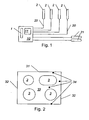
- Fig.2 shows a ceramic hob 33 with heating 3.
- the number, shape and arrangement of the heating areas 3 on a hob can hereby vary as desired.
- Each heating area is assigned a sensor 2 (in Fig. 2 not shown), which is schematically shown in FIG Fig. 1 are shown.
- the measuring sensors 2 are electrically connected via lines 20 to a computing unit 10.
- the sensors 2 are not calibrated for the time being and may be designed, for example, as resistance sensors.
- a standard measuring sensor 1 is furthermore arranged, for example a platinum resistance sensor with known temperature-dependent resistance Rs (T), in particular a PT-100 or PT-1000 sensor.
- the standard sensor 1 supplies the respective current temperature value in the area of the arithmetic unit 10.
- Further measuring sensors 21 can also be arranged in areas 34 outside the heating areas 3.
- the calibration of the individual sensors takes place in such a way that in a first step, the temperature is measured in the cooktop in thermal equilibrium with the aid of the calibrated sensor. In a further step, the resistances of the uncalibrated sensors associated with this temperature are measured. From this information can then easily a calibration factor or the resistance of the sensors at a defined temperature, preferably 25 ° C, determined and then stored.
- the measuring sensors 2 are resistance sensors, in particular platinum resistance sensors, which have a resistance R (T), which is dependent on the respective temperature T and in each case has known electrical resistance coefficients.
- a calibration of the probe 2 is carried out in the temperature equilibrium, in particular before the first start of the heating areas 3, ie substantially at room temperature, because then the temperature at the probes 2 is naturally equal to that of the standard probe 1.
- Corresponding calibration values for the measuring sensors 2 are advantageously stored in a memory unit 11 of the arithmetic unit 10.
- the determination of R 0 is required as a calibration value.
- the objective method is carried out in the temperature equilibrium, preferably before the first start-up of the heating areas 3, because only in the temperature equilibrium can it be assumed that all the sensors 2, 21 and the standard sensor 1 have the same temperature.
- known temperature profiles can also be utilized. So there are, for example, characteristic temperature profiles during the cooling of a heating area 3 after its shutdown. Furthermore, however, the temperature of a sensor 2 of a heating region 3, which is not in operation, according to a characteristic course increase when adjacent heating areas 3 are in operation. Further characteristic temperature profiles as a function of the operating state of adjacent heating areas 3 can also be registered by further measuring sensors 21 outside of heating areas 3. Such characteristic temperature profiles as a function of location, operating state of adjacent heating areas 3 and time can be described as so-called characteristics fields and stored in the memory unit 11.
- the temperature in arbitrary regions 34 for example on the rear wall 31 or sidewalls 32 can therefore be determined by the arithmetic unit 10 from the temperatures at sensors 2, 21 at defined intervals.
- a limit T max be given, when it reaches a process such as an alarm, a switching operation or a
- Control process is triggered. For example, it can be ensured that safety-critical temperatures in certain areas are avoided.
- the current temperature at as many points of the ceramic hob it is advantageous to know the current temperature at as many points of the ceramic hob as possible.
- the calibration of the individual sensors takes place in such a way that in a first step, the temperature is measured in the cooktop in thermal equilibrium with the aid of the calibrated sensor. In a further step, the resistances of the uncalibrated sensors associated with this temperature are measured. From this information can then easily a calibration factor or the resistance of the sensors at a defined temperature, preferably 25 ° C, determined and then stored.
Landscapes
- Physics & Mathematics (AREA)
- General Physics & Mathematics (AREA)
- Control Of Resistance Heating (AREA)
- Measuring Fluid Pressure (AREA)
- Glass Compositions (AREA)
- Indication And Recording Devices For Special Purposes And Tariff Metering Devices (AREA)
- Investigating Or Analyzing Materials Using Thermal Means (AREA)
Abstract
Description
Die Erfindung betrifft einen Messfühler gemäß dem Oberbegriff des Anspruchs 1. Dadurch dass die Kontaktierung außerhalb des Bereiches liegt, in dem die Temperatur erfasst werden soll, werden durch die Kontaktierung entstehende Störeinflüsse bei der Messung vermieden.The invention relates to a measuring sensor according to the preamble of
Bei üblichen Elektroherden, insbesondere mit Keramikkochfeld, sind pro Heizung ein elektromechanischer Schutztemperaturbegrenzer für die Begrenzung auf die maximale Temperatur vorhanden. Wird das Kochfeld mit einer Elektronik gesteuert, so ist eine Substitution der mechanischen Temperaturbegrenzer durch elektronische Temperaturfühler möglich, da die notwendigen Leistungsschalter (Relais) bereits vorhanden sind. Bei den verwendeten elektronischen Steuereinheiten ist häufig auch im Bereich der Elektronik eines Elektroherdes ein Messfühler angeordnet.In conventional electric cookers, in particular with a ceramic hob, an electromechanical protective temperature limiter for limiting the maximum temperature are available per heater. If the hob is controlled by electronics, a substitution of the mechanical temperature limiter by electronic temperature sensors is possible because the necessary circuit breakers (relays) are already present. In the electronic control units used, a sensor is often arranged in the field of electronics of an electric range.
Für die Betriebssicherheit des Kochfeldes ist es wichtig, dass diese Messfühler kalibriert sind und so zuverlässig die Temperatur des jeweiligen Kochfeldes erfassen. Die Kalibrierung von Messfühlern erfordert jedoch einen beträchtlichen Aufwand und verursacht somit nicht unerhebliche Kosten. Beispielsweise müssen Widerstandsmessfühler in irgend einer Form getrimmt werden, wobei dieses Trimmen nicht nur zusätzliche Kosten verursacht, sondern zusätzlich die Qualität des Messfühlers beeinträchtigt sowie die Größe des Messfühlers mitbestimmt.For the safe operation of the hob, it is important that these probes are calibrated and thus reliably detect the temperature of the respective hob. However, the calibration of sensors requires a considerable effort and thus causes considerable costs. For example, resistance probes need to be trimmed in some form, which trimming not only adds expense, but also compromises the quality of the probe and also determines the size of the probe.
Ein spezifisches Anliegen dieser Erfindung ist die Ausgestaltung und Herstellung eines Widerstands-Messfühlers, wobei keine weiteren Kalibrierschritte vor dessen Einbau in das Kochfeld vorgenommen werden müssen. Widerstände, welche auf Grund ihrer definierten temperaturabhängigen elektrischen Leitfähigkeitscharakteristika zur Temperaturmessung herangezogen werden, sind hinlänglich bekannt. Die
Diesen Ausführungen zugrunde liegend beschreibt die
Aus der
Bekannt ist ferner, die Widerstandsbahn von Messfühlern mit unterschiedlichen Längen auszubilden, beispielsweise mit einer Länge im Bereich zwischen 127 mm und 889 mm (
Bekannt sind weiterhin Temperaturmessfühler (
Bekannt sind schließlich Messfühler an einem Kochfeld einer Glas-Keramik-Heizplatte zur Ermittlung der Temperatur des von einer Wärmequelle erwärmten Kochfeldes mit den Merkmalen des Öberbegriffs des Patentanspruches 1 (
Die Aufgabe der Erfindung besteht darin, einen kostengünstigen Messfühler anzugeben, bei dem obige Nachteile vermieden werden, die Designfreiheit eines Kochfeldes durch die geringeren Abmessungen des Temperatursensors erhöht wird, wobei eine maximale Betriebssicherheit des Keramikkochfeldes gewährleistet wird.The object of the invention is to provide a cost-effective sensor, are avoided in the above disadvantages, the design freedom of a hob is increased by the smaller dimensions of the temperature sensor, with maximum reliability of the ceramic hob is guaranteed.
Erfindungsgemäß wird dies durch die Merkmale des Anspruchs 1 erreicht.This is achieved by the features of
Dadurch wird der elektrische Widerstand pro Länge der Widerstandsbahn in diesem Bereich wesentlich herabgesetzt und somit der Einfluss auf die Temperaturmessung in diesem Bereich gering gehalten.As a result, the electrical resistance per length of the resistance path in this area is substantially reduced and thus the influence on the temperature measurement in this area is kept low.
Weiters kann vorgesehen sein, dass sich der Keramikkörper zur Verbesserung der mechanischen Stabilität gegen das freie, von der Kontaktierung abgekehrte Ende hin verjüngt.Furthermore, it can be provided that, in order to improve the mechanical stability, the ceramic body tapers against the free end facing away from the contacting.
So kann bei ausreichender mechanischen Stabilität der Keramikkörper möglichst leicht und materialsparend gehalten werden, wobei weiters insbesondere am von der Kontaktierung abgekehrten Ende die Abschattung der Heizwendel durch den Keramikkörper minimal gehalten werden kann.Thus, with sufficient mechanical stability, the ceramic body can be kept as light and material-saving as possible, wherein furthermore the shadowing of the heating coil can be minimized by the ceramic body, in particular at the end remote from the contacting.
Insbesondere kann vorgesehen sein, dass der Keramikkörper im Bereich der Kontaktierung einen aufgeweiteten Bereich aufweist wobei der Übergang zum übrigen schmäleren Bereich des Keramikkörpers vorzugsweise konkav ausgerundet ist.In particular, it can be provided that the ceramic body has a widened region in the region of the contacting, wherein the transition to the remaining narrower region of the ceramic body is preferably rounded concave.
In besonderer Ausgestaltung der Erfindung kann vorgesehen sein, dass die Widerstandsbahn des Messfühlers mit einer geschlossen Passivierschicht isoliert ist. So wird die Widerstandsbahn zuverlässig vor chemischen Einflüssen geschützt und behält länger ihre thermoelektrischen Eigenschaften, sodass eine zeitliche Drift des Messbereiches minimiert wird.In a particular embodiment of the invention can be provided that the resistance path of the probe is isolated with a closed Passivierschicht. Thus, the resistance path is reliably protected against chemical influences and retains its thermoelectric properties for a longer time, so that a temporal drift of the measuring range is minimized.
Es wird auch ein nicht zur Erfindung gehörendes Verfahren zur Kalibrierung von Temperatur-Messfühlern beschrieben, in einem Heizbereich eines Keramikkochfeldes mit einer Recheneinheit, die mit den Messfühlern über elektrische Leitungen verbunden sind.A method of calibrating temperature sensors which is not part of the invention is also described, in a heating region of a ceramic cooking field with a computing unit, which are connected to the measuring sensors via electrical lines.
Dabei ist es eine Aufgabe, ein Verfahren anzugeben, bei dem kostengünstige, nicht kalibrierte Messfühler im eingebauten Zustand automatisch kalibriert werden, wobei eine maximale Betriebssicherheit des Keramikkochfeldes gewährleistet wird.It is an object to provide a method in which cost-effective, non-calibrated probe are automatically calibrated when installed, with maximum reliability of the ceramic cooktop is guaranteed.
Dies wird dadurch erreicht, dass ein kalibrierter Standardmessfühler beliebiger Ausführung, wie z.B. ein Thermoelement, Thermistor, oder auch ein Platinwiderstandssensor mit bekanntem temperaturabhängigem Widerstand RS(T), insbesondere ein PT-100- oder PT-1000-Sensor, im Bereich der Recheneinheit vorgesehen ist, sodass im Temperaturgleichgewicht, insbesondere vor der ersten Inbetriebnahme der Heizbereiche, die Messfühler mit dem Standardmessfühler abgeglichen werden, und die entsprechenden Kalibrierwerte in einer Speichereinheit der Recheneinheit abgelegt werden. So können auch nicht kalibrierte und somit kostengünstige Messfühler im Bereich des Kochfeldes eingesetzt werden.This is achieved in that a calibrated standard sensor of any design, such as a thermocouple, thermistor, or even a platinum resistance sensor with known temperature-dependent resistance R S (T), in particular a PT-100 or PT-1000 sensor, in the computing unit is provided so that in the temperature equilibrium, in particular before the first use of the heating areas, the sensors are calibrated with the standard sensor, and the corresponding calibration values are stored in a memory unit of the arithmetic unit. This means that non-calibrated and therefore cost-effective sensors can be used in the hob area.
Insbesondere kann vorgesehen sein, dass die Messfühler als Widerstandssensoren mit jeweils einem von der Temperatur T abhängigen Widerstand R(T), insbesondere Platinwiderstandssensoren, mit jeweils bekannten elektrischen Widerstandskoeffizienten und als Kalibrierwert den vorerst unbekanntem Null-Widerstand R0 bei einer Standardtemperatur T0, insbesondere Raumtemperatur, z.B. 25°C, ausgebildet sind, R(T) bei der Temperatur T0 durch die Recheneinheit bestimmt wird, und dass R0 nach der Formel R0 = (1 + α · ΔT)/R(T) berechnet wird, wobei ΔT = T - T0 ist, und der Wert für R0 als Kalibrierwert in der Speichereinheit abgelegt wird. Das Berechnungsverfahren zur Ermittlung von R0 zeichnet sich durch besondere Einfachheit aus und kann auch von einer einfachen und kostengünstigen Recheneinheit ausgeführt werden.In particular, it can be provided that the sensors as resistance sensors, each with a dependent of the temperature T resistance R (T), in particular platinum resistance sensors, each with known electrical resistance coefficient and calibration value the initially unknown zero resistance R 0 at a standard temperature T 0 , in particular Room temperature, for example 25 ° C, are formed, R (T) at the temperature T 0 is determined by the arithmetic unit, and that R 0 is calculated according to the formula R 0 = (1 + α · ΔT) / R (T), where ΔT = T - T 0 , and the value for R 0 is stored as a calibration value in the memory unit. The calculation method for determining R 0 is characterized by particular simplicity and can also be carried out by a simple and cost-effective computing unit.
In Weiterführung kann vorgesehen sein, dass das Verfahren erneut, manuell oder nach einer vorgegebenen Zeitspanne automatisch, ausgelöst wird und die Kalibrierwerte in der Speichereinheit aktualisiert werden. So kann ein zeitlicher Drift der Messfühler zuverlässig ausgeglichen werden und die Genauigkeit der Messfühler auch über einen langen Zeitraum gewährleistet werden.In continuation, it may be provided that the method is triggered again, manually or automatically after a predetermined period of time, and the calibration values in the memory unit are updated. Thus, a time drift of the sensor can be compensated reliably and the accuracy of the probe can be ensured over a long period of time.
In Weiterbildung kann vorgesehen sein, dass die Temperaturen der Heizbereiche in vorgegebenen Zeitintervallen in der Speichereinheit abgelegt werden. So werden auch Temperaturzeitverläufe erfassbar.In a further development it can be provided that the temperatures of the heating areas are stored in the storage unit at predetermined time intervals. So also temperature time courses become detectable.
In Weiterentwicklung kann vorgesehen sein, dass weitere Messfühler in Bereichen außerhalb der Heizbereiche, beispielsweise an Rückwand oder Seitenwänden eines Keramikkochfeldes oder dgl., vorgesehen sind, die in gleicher Weise kalibriert werden wie die Messfühler. So kann erfasst werden, ob Temperaturen, die für z.B. benachbarte Möbel bedenklich wären, überschritten werden.In a further development it can be provided that further measuring sensors are provided in areas outside the heating areas, for example on the rear wall or side walls of a ceramic hob or the like, which are calibrated in the same way as the measuring sensors. Thus, it can be detected whether temperatures which are for e.g. neighboring furniture would be questionable, exceeded.
Schließlich wird ein nicht zur Erfindung gehörendes Verfahren beschrieben zur Berechnung der Temperatur an beliebigen Stellen eines Keramikkochfeldes mit Heizbereichen, Messfühlern in diesen Heizbereichen, die kalibrierbar sind, gegebenenfalls mit weiteren Messfühlern in Bereichen außerhalb der Heizbereiche, beispielsweise an Rückwand oder Seitenwänden, die kalibrierbar sind, weiters mit einer Recheneinheit und einer Speichereinheit.Finally, a method not belonging to the invention is described for calculating the temperature at any point of a ceramic hob with heating areas, sensors in these heating areas that can be calibrated, optionally with further sensors in areas outside the heating areas, for example on the back wall or side walls that can be calibrated, furthermore with a computing unit and a memory unit.
Für eine optimale Betriebssicherheit eines Keramikkochfeldes ist es von Vorteil, die aktuelle Temperatur an möglichst vielen Stellen des Keramikkochfeldes zu kennen. Andererseits ist eine hohe Anzahl von Messfühlern mit hohen Kosten und deren Einbau mit einer Einschränkung der Designfreiheit verbunden.For optimum reliability of a ceramic hob, it is advantageous to know the current temperature at as many points of the ceramic hob as possible. On the other hand, a high number of high-cost sensors and their installation is associated with a restriction of design freedom.
Eine Aufgabe besteht darin, ein Verfahren anzugeben, bei dem obige Nachteile vermieden werden, die Designfreiheit des Keramikkochfeldes erhöht wird und auch mit einer geringen Anzahl von Messfühlern kostensparend eine maximale Betriebssicherheit gewährleistet wird.One object is to provide a method in which the above disadvantages are avoided, the design freedom of the ceramic hob is increased and also with a small number of sensors cost-saving maximum reliability is ensured.
Dies wird dadurch erreicht, dass die Recheneinheit aus den aktuellen Temperaturen an den Messfühlern und den in der Speichereinheit abgelegten Kennlinienfeldern für Temperaturverläufe die aktuelle Temperatur von beliebigen Bereichen des Keramikkochfeldes außerhalb der Heizbereiche ermittelt.This is achieved by the fact that the arithmetic unit determines the current temperature of any areas of the ceramic cooktop outside the heating areas from the current temperatures at the sensors and the characteristic curves for temperature profiles stored in the memory unit.
So kann auch in Bereichen, in deren unmittelbarer Nähe kein Messfühler angeordnet ist, die Temperatur bestimmt und bei vergleichsweise geringer Anzahl von Messfühlern und somit relativ geringen Kosten ein höhere Betriebssicherheit erreicht werden.Thus, even in areas where no sensor is located in the immediate vicinity, determines the temperature and higher reliability can be achieved with a relatively small number of sensors and thus relatively low cost.
Gemäß einer Weiterbildung kann vorgesehen sein, dass die Recheneinheit bei Erreichen eines vorgegebenen Temperaturgrenzwertes Tmax, welcher sowohl für Heizbereiche oder jeden beliebigen Bereich außerhalb der Heizbereiche vorgegeben ist, einen Alarm, einen Schaltvorgang oder einen Regelvorgang auslöst. So wird der Nutzen der Messfühler und die Betriebssicherheit des Keramikkochfelds weiter erhöht.According to a further development, it can be provided that the arithmetic unit triggers an alarm, a switching process or a control process upon reaching a predetermined temperature limit value T max , which is predetermined both for heating areas or any area outside the heating areas. This further increases the benefit of the sensors and the reliability of the ceramic hob.
Es ist somit schlüssig dargelegt und auch das Ziel, dass unter Anwendung dieses Verfahrens mit einer geringen Anzahl von Messfühlern kostensparend eine maximale Betriebssicherheit gewährleistet werden kann.It is thus conclusively set out and also the aim that maximum reliability can be ensured by using this method with a small number of sensors cost-saving.
Die Erfindung wird unter Bezugnahme auf die beigeschlossenen Zeichnungen, in welchen Ausführungsformen dargestellt sind, näher beschrieben. Dabei zeigt:
-
Fig.1 eine schematische Anordnung von Rechnereinheit und Messfühlern, -
Fig.2 eine Draufsicht eines Keramikkochfelds mit Heizbereichen, -
Fig. 3 bis Fig. 7 unterschiedliche Ausformungen eines Messfühlers, -
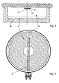
Fig. 8 einen Schnitt durch ein Heizelement, -
Fig. 9 eine Draufsicht auf ein Heizelement, und -
Fig. 10 und Fig. 11 jeweils den Schnitt durch Kontaktierungen der Widerstandsbahn.
-
Fig.1 a schematic arrangement of computer unit and sensors, -
Fig.2 a top view of a ceramic hob with heating areas, -
Fig. 3 to Fig. 7 different shapes of a sensor, -
Fig. 8 a section through a heating element, -
Fig. 9 a plan view of a heating element, and -
10 and FIG. 11 in each case the section through contacts of the resistance path.
Widerstandssensoren sind sehr kostengünstig einsetzbar. Insbesondere Platinwiderstandssensoren zeichnen sich durch eine nur geringe zeitliche Drift aus. Das Berechnungsverfahren zur Ermittlung von R0 zeichnet sich durch besondere Einfachheit aus und kann auch von einer einfachen und daher kostengünstigen Recheneinheit ausgeführt werden.Resistance sensors are very inexpensive to use. In particular, platinum resistance sensors are characterized by only a slight temporal drift. The calculation method for determining R 0 is characterized by particular simplicity and can also be carried out by a simple and therefore cost-effective computing unit.
In weiterer Ausgestaltung der Erfindung ist es vorteilhaft, auch im Hinblick auf kompakte Konstruktion des gesamten Kochfeldes 33, den/die Messfühler 2 im Bereich des Kochfeldes 33nach dem temperaturabhängigen Widerstandsprinzip zu gestalten. Bauartgemäß handelt es sich hierbei um auf Keramik, vorzugsweise auf Al2O3, gedruckte Pt-Dickschichtwiderstandsbahnen, welche derart angeordnet sind, dass die beiden notwendigen elektrischen Kontakte an der gleichen Seite des Keramiksubstrats angeordnet sind.In a further embodiment of the invention, it is advantageous, also with regard to compact construction of the
Anstelle von Pt können auch andere Metalle, Übergangsmetalle und deren Legierungen, welche hinreichend thermooxidationsbeständig sind, als in Form einer Dickschichtswiderstandsbahn zu hier angesprochenen Sensorzwecken verwendet werden.Instead of Pt, other metals, transition metals and their alloys, which are sufficiently resistant to thermal oxidation, can also be used in the form of a thick film resistance track for sensor purposes addressed here.
Ohne auf eine Theorie festgelegt zu sein, haben empirische Versuche gezeigt, dass die Länge der gedruckten Pt-Widerstandsbahn 23, wobei die mit Siebdruck erreichbare Dickschicht nach dem Einbrennen 50 µm nicht übersteigt, für praktische Temperaturmessgenauigkeiten in Glaskeramikkochfeldern 33 signifikant von deren Länge abhängt. Dem folgend wird zwingend vorgeschlagen die Bahnlänge mindestens 200 mm zu wählen. Je nach Messgenauigkeitsanforderung sind erfindungsgemäß weitere Bahnlängen von 250 mm bis 2000 mm und in noch näher definierter Ausgestaltung 320 mm bis 1000 mm anzuwenden.Without wishing to be bound by theory, empirical tests have shown that the length of the printed
Um diese Länge auf der Sensorzunge aufbringen zu können, ist es notwendig, diese mäanderförmig darauf anzuordnen.In order to apply this length on the sensor tongue, it is necessary to arrange them meandering on it.
Die maximale Länge der Sensorzunge ist, wie unschwer zu verstehen, durch den Durchmesser des zu überwachenden Kochfeldes 3 gegeben. Unter Sensorzunge sei die die Widerstandsleiterbahn tragende Keramikkörper 22 welche in das Kochfeld hineinreicht, zu verstehen. Eine bevorzugte Ausführung sieht eine Sensorzungenlänge von max. 3/4 des Kochfelddurchmessers vor. Als weitere erfindungsgemäß bevorzugte Längen sind Abmessungen angegeben, welche von einem Fünftel bis zur Hälfte des Kochfelddurchmessers reichen.The maximum length of the sensor tongue is, as is easy to understand, given by the diameter of the monitored
Die Stegbreite der gedruckten Widerstandsbahnen 23 ist je nach Bahnlänge und Größe des zu überwachenden Kochfeldes 3 zu wählen. Im Regelfall wird eine Stegbreite zwischen 0.01 und 1 mm erfindungsgemäß als Vorteilhaft erachtet. Eine weiters bevorzugte Ausführung sieht Stegbreiten zwischen 0.1 und 0.5 mm vor, was erfindungsgemäß bevorzugt mittels Siebdruck-Technik bewerkstelligt wird. Mittels Siebdruck aufgebrachte Bahnen haben ausreichende Genauigkeit bezüglich Höhe und Breite, was wiederum für den gewünschten Sensorwiderstand von Bedeutung ist. Grundsätzlich jedoch ist jede physikalische Beschichtungsmethode, wie auch z. B. Sputtern geeignet solche elektrisch leitenden Bahnen auf ein Substrat aufzubringen.The web width of the printed resistor tracks 23 is to be selected depending on the track length and size of the
Ein unter Betriebsbedingungen wesentliches Merkmal der gedruckten und eingebrannten Widerstandsbahn stellt der stärker ausgeprägte Abschnitt (23a) der zu den elektrischen Kontakten hinweist dar. Dieser wesentlich dicker aufgebrachte Abschnitt vermag thermomechanische Spannungen, welche durch das Temperaturgefälle zwischen dem Inneren und dem Äußeren des Kochfeldes unter Betriebsbedingungen hervorgerufen werden, soweit aufzunehmen, sodass ein Bruch der gedruckten Leiterbahn in diesem Bereich vermieden wird.A more significant feature of the printed and baked resistor track under operating conditions is the more pronounced portion (23a) of the electrical contacts. This substantially thicker applied portion can cause thermo-mechanical stresses caused by the temperature gradient between the inside and outside of the hob under operating conditions be taken in so far as to avoid breaking the printed circuit trace in this area.
Ein weiterer dadurch erzielter maßgeblicher Effekt, welcher der Genauigkeit des Sensors zuträglich ist, ist die damit verbundene Herabsetzung des elektrischen Widerstandes im selbigen Zuleitungsbereich, welcher naturgemäß mitunter vom Querschnitt abhängig ist.Another significant effect achieved thereby, which is conducive to the accuracy of the sensor, is the associated reduction in the electrical resistance in selb¬ supply area, which is naturally sometimes dependent on the cross-section.
Anders ausgedrückt ist RZuleitung damit sehr viel kleiner als RWiderstandbahn. Damit ergibt sich, dass der vom temperaturabhängigen Widerstandssensor ermittelte Temperaturwert genauer und von allfälligen Temperaturschwankungen im Kontaktierungsbereich nicht, bzw. nur in vernachlässigbar kleinem Ausmaß beeinflusst wird.In other words, R supply line is thus much smaller than R resistance path . This means that the temperature value determined by the temperature-dependent resistance sensor is not influenced more precisely and by possible temperature fluctuations in the contacting region, or only to a negligibly small extent.
Das die Widerstandsbahn tragende Material ist bevorzugt aus Keramik, und in weiters bevorzugter Form aus Al2O3, gefertigt, wobei der Keramikträger erfindungsgemäß verjüngt ausgeführt ist. Diese Verjüngung, welche konkave Verbreiterung zur Sensorkontaktierung hin zu sehen ist (6), zeichnet soweit zur mechanischen Stabilität des Sensors verantwortlich, sodass auf Stützstege und/oder andere konstruktiv sichtbare Verstärkungen verzichtet werden kann.The material carrying the resistance path is preferably made of ceramic, and in a further preferred form of Al 2 O 3 , wherein the ceramic carrier is designed to be tapered according to the invention. This taper, which can be seen concave broadening for sensor contact (6), is responsible for the mechanical stability of the sensor, so that support bars and / or other constructively visible reinforcements can be dispensed with.
Je nach beabsichtigter Sensorgröße und aufzubringender Sensorbahnlänge kann das Substrat in verschiedener Art und Weise verjüngend bevorzugt ausgeführt sein.
Die erfindungsgemäße Formgebung kann sowohl schon im pulvermetallurgisch bedingten Herstellungsprozess erfolgen als auch zu einem späteren Zeitpunkt, wobei aus Keramikplatten mittels Laser die gewünschten Formteile ausgeschnitten werden, welche anschließend einer thermischen Behandlung unterworfen werden. Das bedeutet, dass der Keramikformteil einem Nachsinterprozess zugeführt wird. Nach einem genau definierten Temperaturprogramm werden die ausgeschnittenen Formteile auf Temperaturen bis zu 1600°C geglüht und anschliessend langsam abgekühlt. Dies hat zur Folge, dass das Keramikmaterial unter thermozyklischen Bedingungen, wie sie in einem Kochfeld 3 gegeben sind, keine Risse ausbildet bzw. sich nicht in ungewünschter Weise nachträglich verformt.The shaping according to the invention can both take place already in the powder metallurgy-related manufacturing process as well as at a later time, being cut out of ceramic plates by laser, the desired moldings, which are then subjected to a thermal treatment. This means that the ceramic molding is fed to a Nachsinterprozess. After a well-defined temperature program, the cut moldings are annealed to temperatures up to 1600 ° C and then slowly cooled. This has the consequence that the ceramic material under thermocycling conditions, as they are given in a
Vorzugsweise wird dieser Temperatubehandlungsschritt mit dem Einbrennen der aufgedruckten Widerstandsbahn 23 kombiniert.Preferably, this temperature treatment step is combined with the baking of the printed
Zusätzlich wird erfindungsgemäß bevorzugt, zum Schutz und gegebenenfalls zur Isolierung der Widerstandsbahn 23, über selbige eine Glas oder Glaskeramikschicht aufgebracht. Die Aufbringung erfolgt wiederum mittels Siebdruck-Technik. Diese schützende, isolierende Isolierschicht 26 wird anschließend durch Einbrennen, bei oder knapp unter der Schmelztemperatur der angewendeten Glas oder Keramikfritte auf dem die Widerstandsbahn 23 tragenden Substrat fixiert.In addition, it is preferred according to the invention for the protection and, if appropriate, for the isolation of the
Elektrischer Kontakt zwischen der Kontaktierung 41 und der Widerstandsbahn 23 kann über ein Metallband 42 erfolgen, dass von der Kontaktierung 41 über einen Schlitz im Keramikkörper 22 mit der Widerstandsbahn 23 verbunden ist (siehe
Auch kann eine federnde Kontaktierung 41 a über eine Niete 43 mit dem Keramikkörper 22 verbunden sein, wobei die Widerstandbahn 23 dann zwischen die federnde Kontaktierung 41a und den Keramikkörper 22 geklemmt ist.Also, a
Im Bereich der Recheneinheit 10 ist weiters ein Standardmessfühler 1 angeordnet, beispielsweise ein Platinwiderstandssensor mit bekanntem temperaturabhängigem Widerstand Rs(T), insbesondere ein PT-100- oder PT-1000-Sensor. In Zusammenwirkung mit der Recheneinheit 10 liefert der Standardmessfühler 1 den jeweils aktuellen Temperaturwert im Bereich der Recheneinheit 10.In the area of the
Weitere Messfühler 21 können auch in Bereichen 34 außerhalb der Heizbereiche 3 angeordnet sein.Further measuring
Die Kalibrierung der einzelnen Sensoren erfolgt dabei in der Art, dass in einem ersten Schritt die Temperatur in der im thermischen Gleichgewicht befindlichen Kochmulde mit Hilfe des kalibrierten Messfühlers gemessen wird. In einem weiteren Schritt werden nun die zu dieser Temperatur zugehörigen Widerstände der nicht kalibrierten Sensoren gemessen. Aus dieser Information kann dann auf einfache Weise ein Kalibierfaktor bzw. der Widerstand der Sensoren bei definierten Temperatur, vorzugsweise 25°C, ermittelt und anschließend gespeichert werden.The calibration of the individual sensors takes place in such a way that in a first step, the temperature is measured in the cooktop in thermal equilibrium with the aid of the calibrated sensor. In a further step, the resistances of the uncalibrated sensors associated with this temperature are measured. From this information can then easily a calibration factor or the resistance of the sensors at a defined temperature, preferably 25 ° C, determined and then stored.
Die Messfühler 2 sind Widerstandssensoren, insbesondere Platinwiderstandssensoren, welche einen von der jeweiligen Temperatur T abhängigen Widerstand R(T) mit jeweils bekannten elektrischen Widerstandskoeffizienten haben. Als Kalibrierwert den vorerst unbekanntem Null-Widerstand R0 bei einer Standardtemperatur T0, insbesondere Raumtemperatur, z.B. 25°C, ausgebildet sind, R(T) bei der Temperatur T0 durch die Recheneinheit (10) bestimmt wird, und dass R0 nach der Formel R0 = (1 + α · ΔT)/R(T) berechnet wird, wobei ΔT = T - T0 ist, und der Wert für R0 als Kalibrierwert in der Speichereinheit (11) abgelegt wird.The measuring
Eine Kalibrierung der Messfühler 2 erfolgt im Temperaturgleichgewicht, insbesondere vor der ersten Inbetriebnahme der Heizbereiche 3, also im Wesentlichen bei Raumtemperatur, weil dann die Temperatur an den Messfühlern 2 naturgemäß gleich jener am Standardmessfühler 1 ist. Entsprechende Kalibrierwerte für die Messfühler 2 werden vorteilhafter Weise in einer Speichereinheit 11 der Recheneinheit 10 abgelegt.A calibration of the
Wenn die Messfühler 2 als Widerstandssensoren ausgebildet sind, verhält sich ihr temperaturabhängiger Widerstand R(T) gemäß ![]()
![]()
![]()
![]()
Gegenständliches Verfahren wird im Temperaturgleichgewicht, vorzugsweise vor der ersten Inbetriebnahme der Heizbereiche 3, durchgeführt, weil nur im Temperaturgleichgewicht davon ausgegangen werden kann, dass alle Messfühler 2, 21 und der Standardmessfühler 1 die gleiche Temperatur aufweisen.The objective method is carried out in the temperature equilibrium, preferably before the first start-up of the
Um ein Driften der Messfühler 2, 21 zu vermeiden und auch nach längerer Zeit die Genauigkeit derselben gewährleisten zu können, kann auch zu einem späteren Zeitpunkt das Verfahren zur Kalibrierung von Messfühlern 2, 21 ausgeführt werden, sodass die Kalibrierwerte aktualisiert und in der Speichereinheit 11 abgelegt werden. Diese erneute Kalibrierung kann händisch ausgelöst werden, oder nach einer vorgegebenen Zeitspanne, insbesondere nach einer für ein Temperaturgleichgewicht notwendigen Mindestdauer nach der letzten Inbetriebnahme der Heizbereiche 3, automatisch gestartet werden.In order to avoid drifting of the
Weiters können zur Ermittlung der Temperaturen beispielsweise in Heizbereichen 3 auch bekannte Temperaturverläufe nutzbar gemacht werden. So Gibt es beispielsweise charakteristische Temperaturverläufe bei der Abkühlung eines Heizbereichs 3 nach dessen Abschaltung. Weiters wird aber auch die Temperatur eines Messfühlers 2 eines Heizbereichs 3, der nicht in Betrieb ist, nach einem charakteristischen Verlauf zunehmen, wenn benachbarte Heizbereiche 3 in Betrieb sind. Weitere charakteristische Temperaturverläufe in Abhängigkeit vom Betriebszustand benachbarter Heizbereiche 3 können auch von weiteren Messfühlern 21 außerhalb von Heizbereichen 3 registriert werden. Solche charakteristischen Temperaturverläufe in Abhängigkeit von Ort, Betriebszustand benachbarter Heizbereiche 3 und Zeit können als sogenannte Kennlinienfelder beschrieben und in der Speichereinheit 11 abgelegt werden. Bei Kenntnis der entsprechenden Wärmeübertragungseigenschaften in einem Keramikkochfeld 33 und den entsprechenden Kennlinienfelder kann daher durch die Recheneinheit 10 die Temperatur in beliebigen Bereichen 34, beispielsweise an Rückwand 31 oder Seitenwänden 32 aus den Temperaturen an Messfühlern 2, 21 in definierten Abständen ermittelt werden.Furthermore, for determining the temperatures, for example in
Nun kann zur Erhöhung der Betriebssicherheit für verschiedenen Bereiche 34 außerhalb der Heizbereiche, aber auch für Heizbereich 3 selbst, ein Grenzwert Tmax vorgegeben sein, bei dessen Erreichung ein Vorgang, wie beispielsweise ein Alarm, ein Schaltvorgang oder einNow, to increase the reliability of
Regelvorgang, ausgelöst wird. So kann beispielsweise gewährleistet werden, dass sicherheitsbedenkliche Temperaturen in bestimmten Bereichen vermieden werden.Control process is triggered. For example, it can be ensured that safety-critical temperatures in certain areas are avoided.
Für eine optimale Betriebssicherheit eines Keramikkochfeldes ist es von Vorteil, die aktuelle Temperatur an möglichst vielen Stellen des Keramikkochfeldes zu kennen. Die Kalibrierung der einzelnen Sensoren erfolgt dabei in der Art, dass in einem ersten Schritt die Temperatur in der im thermischen Gleichgewicht befindlichen Kochmulde mit Hilfe des kalibrierten Messfühlers gemessen wird. In einem weiteren Schritt werden nun die zu dieser Temperatur zugehörigen Widerstände der nicht kalibrierten Sensoren gemessen. Aus dieser Information kann dann auf einfache Weise ein Kalibierfaktor bzw. der Widerstand der Sensoren bei definierten Temperatur, vorzugsweise 25°C, ermittelt und anschließend gespeichert werden.For optimum reliability of a ceramic hob, it is advantageous to know the current temperature at as many points of the ceramic hob as possible. The calibration of the individual sensors takes place in such a way that in a first step, the temperature is measured in the cooktop in thermal equilibrium with the aid of the calibrated sensor. In a further step, the resistances of the uncalibrated sensors associated with this temperature are measured. From this information can then easily a calibration factor or the resistance of the sensors at a defined temperature, preferably 25 ° C, determined and then stored.
Claims (4)
- Sensor (2) for determining the mean value of the temperature of a heated area (3) of a glass-ceramic hot plate heated by a heat source, wherein the sensor (2) can be mounted between the heat source and the glass-ceramic hot plate and parallel to same, wherein the sensor (2) comprises a ceramic body (22) and a temperature-dependent resistance sheet (23) which is placed on the ceramic body (22) and which can be arranged away from the heated area (3), wherein the resistance sheet (23) is in conductive connection outside of the area in which the temperature is to be determined, to the contacting faces of an external electric contactor (41a) characterised in that the length of the resistance sheet (23) amounts to at least 200 mm, that the resistance sheet (23) is formed in an area (23a) of the resistance sheet, which is clearly distinguishable from the electric contactor (41a) between the contactor (41a) and a temperature-sensitive area of the resistance sheet (23) intended for determining the temperature, with a larger more particularly with at least double the cross-sectional size, compared with the cross-sectional size in the temperature-sensitive area, and that for a contactor (41a) of the resistance sheet (23) contacting members of an elastically resistant material are provided which are riveted to the ceramic body (22) and are provided with surface dents facing the resistance sheet (23) so that the resistance sheet (23) is clamped at its areas (23a) with the larger cross-section each between the contact (41a) and the ceramic body (22).
- Sensor according to claim 1 characterised in that the ceramic body (22) tapers towards its free end remote from the contactor (41a) in order to improve the mechanical stability.
- Sensor according to claim 1 or 2 characterised in that the ceramic body (22) has in the region of the contactor (41a) a widened area wherein the transition to the remaining narrower area of the ceramic body (22) is preferably rounded concave.
- Sensor according to one of claims 1 to 3 characterised in that the resistance sheet (23) of the sensor (2) is insulated with a closed passivation coating (26).
Priority Applications (7)
| Application Number | Priority Date | Filing Date | Title |
|---|---|---|---|
| EP04004153.5A EP1568980B2 (en) | 2004-02-24 | 2004-02-24 | Temperature sensor |
| DE502004004371T DE502004004371D1 (en) | 2004-02-24 | 2004-02-24 | Temperature sensor |
| EP05018737A EP1619485B8 (en) | 2004-02-24 | 2004-02-24 | Temperature sensor |
| AT04004153T ATE332493T1 (en) | 2004-02-24 | 2004-02-24 | TEMPERATURE PROBE |
| AT05018737T ATE367573T1 (en) | 2004-02-24 | 2004-02-24 | TEMPERATURE PROBE |
| DE502004000918T DE502004000918D1 (en) | 2004-02-24 | 2004-02-24 | Temperature sensor |
| US11/065,435 US7214909B2 (en) | 2004-02-24 | 2005-02-24 | Temperature sensor |
Applications Claiming Priority (1)
| Application Number | Priority Date | Filing Date | Title |
|---|---|---|---|
| EP04004153.5A EP1568980B2 (en) | 2004-02-24 | 2004-02-24 | Temperature sensor |
Related Child Applications (2)
| Application Number | Title | Priority Date | Filing Date |
|---|---|---|---|
| EP05018737A Division EP1619485B8 (en) | 2004-02-24 | 2004-02-24 | Temperature sensor |
| EP05018737.6 Division-Into | 2005-08-30 |
Publications (3)
| Publication Number | Publication Date |
|---|---|
| EP1568980A1 EP1568980A1 (en) | 2005-08-31 |
| EP1568980B1 EP1568980B1 (en) | 2006-07-05 |
| EP1568980B2 true EP1568980B2 (en) | 2013-08-14 |
Family
ID=34745870
Family Applications (2)
| Application Number | Title | Priority Date | Filing Date |
|---|---|---|---|
| EP05018737A Expired - Lifetime EP1619485B8 (en) | 2004-02-24 | 2004-02-24 | Temperature sensor |
| EP04004153.5A Expired - Lifetime EP1568980B2 (en) | 2004-02-24 | 2004-02-24 | Temperature sensor |
Family Applications Before (1)
| Application Number | Title | Priority Date | Filing Date |
|---|---|---|---|
| EP05018737A Expired - Lifetime EP1619485B8 (en) | 2004-02-24 | 2004-02-24 | Temperature sensor |
Country Status (4)
| Country | Link |
|---|---|
| US (1) | US7214909B2 (en) |
| EP (2) | EP1619485B8 (en) |
| AT (2) | ATE332493T1 (en) |
| DE (2) | DE502004000918D1 (en) |
Families Citing this family (15)
| Publication number | Priority date | Publication date | Assignee | Title |
|---|---|---|---|---|
| AT8257U1 (en) * | 2005-04-19 | 2006-04-15 | Electrovac | SENSOR ARRANGEMENT |
| DE102005040041B3 (en) * | 2005-08-23 | 2006-10-19 | Miele & Cie. Kg | Glass ceramic cooking plate, for a cooker/hob, is within an insulation and is fitted with a lower temperature monitor to hold the radiated heat from the upper surface at a given level |
| DE102006010107A1 (en) * | 2006-03-01 | 2007-09-06 | E.G.O. Elektro-Gerätebau GmbH | Method and device for detecting a temperature sensor connected to a control |
| GB2446414A (en) * | 2007-02-06 | 2008-08-13 | Thorn Security | A Detector |
| WO2008117909A1 (en) * | 2007-03-28 | 2008-10-02 | Lg Electronics Inc. | Heat detecting device, cooking apparatus using the same and a method of controoling the cooking apparatus |
| KR101261647B1 (en) * | 2007-03-28 | 2013-05-06 | 엘지전자 주식회사 | Control method of heating apparatus |
| DE102007046900C5 (en) | 2007-09-28 | 2018-07-26 | Heraeus Sensor Technology Gmbh | High-temperature sensor and a method for its production |
| IT1393070B1 (en) * | 2008-10-24 | 2012-04-11 | Worgas Bruciatori Srl | SPECIAL THERMOCOUPLE FOR BURNERS |
| EP2467345A1 (en) * | 2009-08-17 | 2012-06-27 | BSH Bosch und Siemens Hausgeräte GmbH | Cover plate for a domestic appliance, said cover plate having at least one semi-transparent support plate, domestic appliance for preparing food and method for producing a cover plate for a domestic appliance |
| DE102013110046B4 (en) | 2013-09-12 | 2023-03-16 | Endress+Hauser Conducta Gmbh+Co. Kg | Method and electrical circuit for determining a physical and/or chemical temperature-dependent process variable |
| CN104501988B (en) * | 2014-12-16 | 2017-09-08 | 南京时恒电子科技有限公司 | A kind of preparation method of wide warm area high accuracy NTC temperature sensors |
| US20160227609A1 (en) * | 2015-01-30 | 2016-08-04 | Schott Corporation | Multi function glass or glass-ceramic cooktop system and method of cooking thereon |
| CN104655304A (en) * | 2015-03-01 | 2015-05-27 | 吴传涛 | Furnace temperature probe for industrial direct-burning furnace |
| CN107889300A (en) * | 2016-09-29 | 2018-04-06 | 浙江久康电器有限公司 | The electrical heating stove of plug-in type infrared ray electric heat stove plate and the dress electric heating furnace tray |
| DE102017115946A1 (en) * | 2017-07-14 | 2019-01-17 | Borgwarner Ludwigsburg Gmbh | Method for controlling the temperature of a glow plug |
Citations (8)
| Publication number | Priority date | Publication date | Assignee | Title |
|---|---|---|---|---|
| GB1415644A (en) † | 1971-11-18 | 1975-11-26 | Johnson Matthey Co Ltd | Resistance thermometer element |
| GB2006521A (en) † | 1977-09-13 | 1979-05-02 | Johnson Matthey Co Ltd | Resistance thermometers |
| US4371861A (en) † | 1980-12-11 | 1983-02-01 | Honeywell Inc. | Ni-fe thin-film temperature sensor |
| US4708769A (en) † | 1984-08-16 | 1987-11-24 | Robert Bosch Gmbh | Temperature dependent electric resistor probe and a method of making the same |
| EP0437356A2 (en) † | 1990-01-11 | 1991-07-17 | General Electric Company | Temperature sensors |
| US5430428A (en) † | 1991-02-15 | 1995-07-04 | Siemens Aktiengesellschaft | High-temperature sensor made of metal of the platinum group |
| US5823680A (en) † | 1993-12-27 | 1998-10-20 | Ngk Insulators, Ltd. | Temperature sensor |
| US20030072352A1 (en) † | 2001-10-15 | 2003-04-17 | Heraeus Sensor-Nite Gmbh | Temperature sensor with a sensor element and use thereof |
Family Cites Families (14)
| Publication number | Priority date | Publication date | Assignee | Title |
|---|---|---|---|---|
| US1697954A (en) * | 1925-10-10 | 1929-01-08 | Shakeproof Lock Washer Co | Electrical connecter |
| US3892947A (en) * | 1974-02-27 | 1975-07-01 | Donnelly Mirrors Inc | Electrically heated panel with anti-shock conductive strips |
| EP0063264B1 (en) | 1980-04-16 | 1984-12-12 | Kabushiki Kaisha Kirk | Method for the manufacture of a temperature sensitive platinum thin film resistance element |
| DE3100852A1 (en) | 1981-01-14 | 1982-08-12 | Draloric Electronic GmbH, 6000 Frankfurt | Electrical component |
| DE8109131U1 (en) * | 1981-03-27 | 1981-08-20 | E.G.O. Elektro-Geräte Blanc u. Fischer, 7519 Oberderdingen | TEMPERATURE DETECTOR FOR ELECTRIC RADIATORS |
| GB2103910B (en) * | 1981-08-08 | 1985-08-21 | Micropore International Ltd | Improvements in electric cookers incorporating radiant heaters |
| US4815198A (en) * | 1985-04-29 | 1989-03-28 | Ford Motor Company | Method for making a part of an electrically heated windshield assembly |
| US5288973A (en) * | 1991-12-28 | 1994-02-22 | Rohm Co., Ltd. | Heater for sheet material |
| EP0806886B1 (en) * | 1996-05-11 | 2005-01-26 | AEG Hausgeräte GmbH | Method and device for measuring the temperature on a hot plate with a track thermo sensor |
| DE19632057C2 (en) * | 1996-08-09 | 2000-06-21 | Schott Glas | Method for calibrating temperature measuring resistors on supports made of glass, glass ceramic or the like |
| DE19925367A1 (en) * | 1998-07-09 | 2000-01-13 | Electrovac | Temperature sensor |
| DE19901184C1 (en) * | 1999-01-14 | 2000-10-26 | Sensotherm Temperatursensorik | Platinum temperature sensor and method of manufacturing the same |
| US6588931B2 (en) * | 2000-12-07 | 2003-07-08 | Delphi Technologies, Inc. | Temperature sensor with flexible circuit substrate |
| GB0116884D0 (en) * | 2001-07-11 | 2001-09-05 | Ceramaspeed Ltd | Temperature sensor assembly and radiant electric heater incorporating the same |
-
2004
- 2004-02-24 AT AT04004153T patent/ATE332493T1/en active
- 2004-02-24 DE DE502004000918T patent/DE502004000918D1/en not_active Expired - Lifetime
- 2004-02-24 EP EP05018737A patent/EP1619485B8/en not_active Expired - Lifetime
- 2004-02-24 EP EP04004153.5A patent/EP1568980B2/en not_active Expired - Lifetime
- 2004-02-24 DE DE502004004371T patent/DE502004004371D1/en not_active Expired - Lifetime
- 2004-02-24 AT AT05018737T patent/ATE367573T1/en active
-
2005
- 2005-02-24 US US11/065,435 patent/US7214909B2/en not_active Expired - Fee Related
Patent Citations (8)
| Publication number | Priority date | Publication date | Assignee | Title |
|---|---|---|---|---|
| GB1415644A (en) † | 1971-11-18 | 1975-11-26 | Johnson Matthey Co Ltd | Resistance thermometer element |
| GB2006521A (en) † | 1977-09-13 | 1979-05-02 | Johnson Matthey Co Ltd | Resistance thermometers |
| US4371861A (en) † | 1980-12-11 | 1983-02-01 | Honeywell Inc. | Ni-fe thin-film temperature sensor |
| US4708769A (en) † | 1984-08-16 | 1987-11-24 | Robert Bosch Gmbh | Temperature dependent electric resistor probe and a method of making the same |
| EP0437356A2 (en) † | 1990-01-11 | 1991-07-17 | General Electric Company | Temperature sensors |
| US5430428A (en) † | 1991-02-15 | 1995-07-04 | Siemens Aktiengesellschaft | High-temperature sensor made of metal of the platinum group |
| US5823680A (en) † | 1993-12-27 | 1998-10-20 | Ngk Insulators, Ltd. | Temperature sensor |
| US20030072352A1 (en) † | 2001-10-15 | 2003-04-17 | Heraeus Sensor-Nite Gmbh | Temperature sensor with a sensor element and use thereof |
Also Published As
| Publication number | Publication date |
|---|---|
| US7214909B2 (en) | 2007-05-08 |
| EP1619485B8 (en) | 2007-10-03 |
| DE502004000918D1 (en) | 2006-08-17 |
| US20050184044A1 (en) | 2005-08-25 |
| EP1568980B1 (en) | 2006-07-05 |
| EP1619485B1 (en) | 2007-07-18 |
| ATE332493T1 (en) | 2006-07-15 |
| ATE367573T1 (en) | 2007-08-15 |
| DE502004004371D1 (en) | 2007-08-30 |
| EP1619485A1 (en) | 2006-01-25 |
| EP1568980A1 (en) | 2005-08-31 |
Similar Documents
| Publication | Publication Date | Title |
|---|---|---|
| EP1568980B2 (en) | Temperature sensor | |
| DE4022845C2 (en) | ||
| EP1989922B1 (en) | Method and apparatus for identifying a temperature sensor connected to a controller | |
| DE102004022206B4 (en) | Sensor for measuring thermal conductivity comprises a strip composed of two parallel sections, and two outer heating strips | |
| DE69117374T2 (en) | SiC thin film thermistor and method and manufacturing process. | |
| EP1936279B1 (en) | Method and device for evaluating the amount of vapour over time emitted by the food during cooking in an oven cavity | |
| EP1152639B1 (en) | Electrical heating unit, particularly for liquid supports | |
| DE202010005756U1 (en) | Electronic component, in particular current sensor | |
| DE2644883B2 (en) | Moisture sensitive resistance device | |
| DE102013200277A1 (en) | Heating device has measuring device that is connected to planar electrode and heating conductor, for detecting temperature dependent current flow between heating conductor and covering layer and/or dielectric insulation layer | |
| EP2145166B1 (en) | Resistance thermometer | |
| DE19647985A1 (en) | Detecting cooking point of cooking position with conducting track temp. sensor | |
| DE2139828C3 (en) | Temperature measuring resistor with high thermal shock resistance made of glass ceramic | |
| WO2014095425A2 (en) | Sensor element, thermometer and method for determining a temperature | |
| EP0823620B1 (en) | Method for calibrating temperature measuring resistances on substrates of glass, glass-ceramic or similar | |
| EP3404405A1 (en) | Sensor for the determination of gas parameters | |
| DE19646826C2 (en) | Device for measuring the temperature of hotplates | |
| DE69814877T2 (en) | ELECTRIC LIQUID HEATING DEVICE | |
| WO2009027042A1 (en) | Heating device, method for operating a heating device and electric heating apparatus of such a heating device | |
| EP1715316B1 (en) | Measuring sensor system | |
| DE102013206406B4 (en) | Room air conditioner and control device | |
| DE10206045B4 (en) | Quasi-stationary method for measuring the thermal conductivity | |
| DE19707664C2 (en) | Device and method for controlling or regulating the temperature of heated surfaces | |
| DE1943748A1 (en) | Heating and temperature measuring device | |
| EP0806886B1 (en) | Method and device for measuring the temperature on a hot plate with a track thermo sensor |
Legal Events
| Date | Code | Title | Description |
|---|---|---|---|
| PUAI | Public reference made under article 153(3) epc to a published international application that has entered the european phase |
Free format text: ORIGINAL CODE: 0009012 |
|
| 17P | Request for examination filed |
Effective date: 20050404 |
|
| AK | Designated contracting states |
Kind code of ref document: A1 Designated state(s): AT BE BG CH CY CZ DE DK EE ES FI FR GB GR HU IE IT LI LU MC NL PT RO SE SI SK TR |
|
| AX | Request for extension of the european patent |
Extension state: AL LT LV MK |
|
| GRAP | Despatch of communication of intention to grant a patent |
Free format text: ORIGINAL CODE: EPIDOSNIGR1 |
|
| AKX | Designation fees paid |
Designated state(s): AT BE BG CH CY CZ DE DK EE ES FI FR GB GR HU IE IT LI LU MC NL PT RO SE SI SK TR |
|
| GRAS | Grant fee paid |
Free format text: ORIGINAL CODE: EPIDOSNIGR3 |
|
| GRAA | (expected) grant |
Free format text: ORIGINAL CODE: 0009210 |
|
| AK | Designated contracting states |
Kind code of ref document: B1 Designated state(s): AT BE BG CH CY CZ DE DK EE ES FI FR GB GR HU IE IT LI LU MC NL PT RO SE SI SK TR |
|
| PG25 | Lapsed in a contracting state [announced via postgrant information from national office to epo] |
Ref country code: IT Free format text: LAPSE BECAUSE OF FAILURE TO SUBMIT A TRANSLATION OF THE DESCRIPTION OR TO PAY THE FEE WITHIN THE PRESCRIBED TIME-LIMIT;WARNING: LAPSES OF ITALIAN PATENTS WITH EFFECTIVE DATE BEFORE 2007 MAY HAVE OCCURRED AT ANY TIME BEFORE 2007. THE CORRECT EFFECTIVE DATE MAY BE DIFFERENT FROM THE ONE RECORDED. Effective date: 20060705 Ref country code: NL Free format text: LAPSE BECAUSE OF FAILURE TO SUBMIT A TRANSLATION OF THE DESCRIPTION OR TO PAY THE FEE WITHIN THE PRESCRIBED TIME-LIMIT Effective date: 20060705 Ref country code: FI Free format text: LAPSE BECAUSE OF FAILURE TO SUBMIT A TRANSLATION OF THE DESCRIPTION OR TO PAY THE FEE WITHIN THE PRESCRIBED TIME-LIMIT Effective date: 20060705 Ref country code: CZ Free format text: LAPSE BECAUSE OF FAILURE TO SUBMIT A TRANSLATION OF THE DESCRIPTION OR TO PAY THE FEE WITHIN THE PRESCRIBED TIME-LIMIT Effective date: 20060705 Ref country code: IE Free format text: LAPSE BECAUSE OF FAILURE TO SUBMIT A TRANSLATION OF THE DESCRIPTION OR TO PAY THE FEE WITHIN THE PRESCRIBED TIME-LIMIT Effective date: 20060705 Ref country code: RO Free format text: LAPSE BECAUSE OF FAILURE TO SUBMIT A TRANSLATION OF THE DESCRIPTION OR TO PAY THE FEE WITHIN THE PRESCRIBED TIME-LIMIT Effective date: 20060705 Ref country code: SK Free format text: LAPSE BECAUSE OF FAILURE TO SUBMIT A TRANSLATION OF THE DESCRIPTION OR TO PAY THE FEE WITHIN THE PRESCRIBED TIME-LIMIT Effective date: 20060705 Ref country code: SI Free format text: LAPSE BECAUSE OF FAILURE TO SUBMIT A TRANSLATION OF THE DESCRIPTION OR TO PAY THE FEE WITHIN THE PRESCRIBED TIME-LIMIT Effective date: 20060705 |
|
| REG | Reference to a national code |
Ref country code: GB Ref legal event code: FG4D Free format text: NOT ENGLISH |
|
| REG | Reference to a national code |
Ref country code: CH Ref legal event code: EP |
|
| REG | Reference to a national code |
Ref country code: IE Ref legal event code: FG4D Free format text: LANGUAGE OF EP DOCUMENT: GERMAN |
|
| REF | Corresponds to: |
Ref document number: 502004000918 Country of ref document: DE Date of ref document: 20060817 Kind code of ref document: P |
|
| PG25 | Lapsed in a contracting state [announced via postgrant information from national office to epo] |
Ref country code: BG Free format text: LAPSE BECAUSE OF FAILURE TO SUBMIT A TRANSLATION OF THE DESCRIPTION OR TO PAY THE FEE WITHIN THE PRESCRIBED TIME-LIMIT Effective date: 20061005 Ref country code: DK Free format text: LAPSE BECAUSE OF FAILURE TO SUBMIT A TRANSLATION OF THE DESCRIPTION OR TO PAY THE FEE WITHIN THE PRESCRIBED TIME-LIMIT Effective date: 20061005 Ref country code: SE Free format text: LAPSE BECAUSE OF FAILURE TO SUBMIT A TRANSLATION OF THE DESCRIPTION OR TO PAY THE FEE WITHIN THE PRESCRIBED TIME-LIMIT Effective date: 20061005 |
|
| RAP2 | Party data changed (patent owner data changed or rights of a patent transferred) |
Owner name: ELECTROVAC AG |
|
| PG25 | Lapsed in a contracting state [announced via postgrant information from national office to epo] |
Ref country code: ES Free format text: LAPSE BECAUSE OF FAILURE TO SUBMIT A TRANSLATION OF THE DESCRIPTION OR TO PAY THE FEE WITHIN THE PRESCRIBED TIME-LIMIT Effective date: 20061016 |
|
| GBT | Gb: translation of ep patent filed (gb section 77(6)(a)/1977) |
Effective date: 20061020 |
|
| NLT2 | Nl: modifications (of names), taken from the european patent patent bulletin |
Owner name: ELECTROVAC AG Effective date: 20061011 |
|
| NLV1 | Nl: lapsed or annulled due to failure to fulfill the requirements of art. 29p and 29m of the patents act | ||
| PG25 | Lapsed in a contracting state [announced via postgrant information from national office to epo] |
Ref country code: PT Free format text: LAPSE BECAUSE OF FAILURE TO SUBMIT A TRANSLATION OF THE DESCRIPTION OR TO PAY THE FEE WITHIN THE PRESCRIBED TIME-LIMIT Effective date: 20061205 |
|
| REG | Reference to a national code |
Ref country code: IE Ref legal event code: FD4D |
|
| PG25 | Lapsed in a contracting state [announced via postgrant information from national office to epo] |
Ref country code: MC Free format text: LAPSE BECAUSE OF NON-PAYMENT OF DUE FEES Effective date: 20070228 |
|
| PLBI | Opposition filed |
Free format text: ORIGINAL CODE: 0009260 |
|
| PLAX | Notice of opposition and request to file observation + time limit sent |
Free format text: ORIGINAL CODE: EPIDOSNOBS2 |
|
| EN | Fr: translation not filed | ||
| 26 | Opposition filed |
Opponent name: CERAMASPEED LIMITED Effective date: 20070403 |
|
| PLBB | Reply of patent proprietor to notice(s) of opposition received |
Free format text: ORIGINAL CODE: EPIDOSNOBS3 |
|
| BERE | Be: lapsed |
Owner name: ELECTROVAC, FABRIKATION ELEKTROTECHNISCHER SPEZIA Effective date: 20070228 |
|
| PG25 | Lapsed in a contracting state [announced via postgrant information from national office to epo] |
Ref country code: BE Free format text: LAPSE BECAUSE OF NON-PAYMENT OF DUE FEES Effective date: 20070228 |
|
| PG25 | Lapsed in a contracting state [announced via postgrant information from national office to epo] |
Ref country code: GR Free format text: LAPSE BECAUSE OF FAILURE TO SUBMIT A TRANSLATION OF THE DESCRIPTION OR TO PAY THE FEE WITHIN THE PRESCRIBED TIME-LIMIT Effective date: 20061006 Ref country code: FR Free format text: LAPSE BECAUSE OF FAILURE TO SUBMIT A TRANSLATION OF THE DESCRIPTION OR TO PAY THE FEE WITHIN THE PRESCRIBED TIME-LIMIT Effective date: 20070511 |
|
| PG25 | Lapsed in a contracting state [announced via postgrant information from national office to epo] |
Ref country code: EE Free format text: LAPSE BECAUSE OF FAILURE TO SUBMIT A TRANSLATION OF THE DESCRIPTION OR TO PAY THE FEE WITHIN THE PRESCRIBED TIME-LIMIT Effective date: 20060705 |
|
| REG | Reference to a national code |
Ref country code: CH Ref legal event code: PL |
|
| PG25 | Lapsed in a contracting state [announced via postgrant information from national office to epo] |
Ref country code: LI Free format text: LAPSE BECAUSE OF NON-PAYMENT OF DUE FEES Effective date: 20080229 Ref country code: CH Free format text: LAPSE BECAUSE OF NON-PAYMENT OF DUE FEES Effective date: 20080229 |
|
| PG25 | Lapsed in a contracting state [announced via postgrant information from national office to epo] |
Ref country code: FR Free format text: LAPSE BECAUSE OF FAILURE TO SUBMIT A TRANSLATION OF THE DESCRIPTION OR TO PAY THE FEE WITHIN THE PRESCRIBED TIME-LIMIT Effective date: 20060705 |
|
| PLAB | Opposition data, opponent's data or that of the opponent's representative modified |
Free format text: ORIGINAL CODE: 0009299OPPO |
|
| PG25 | Lapsed in a contracting state [announced via postgrant information from national office to epo] |
Ref country code: CY Free format text: LAPSE BECAUSE OF FAILURE TO SUBMIT A TRANSLATION OF THE DESCRIPTION OR TO PAY THE FEE WITHIN THE PRESCRIBED TIME-LIMIT Effective date: 20060705 Ref country code: LU Free format text: LAPSE BECAUSE OF NON-PAYMENT OF DUE FEES Effective date: 20070224 |
|
| PG25 | Lapsed in a contracting state [announced via postgrant information from national office to epo] |
Ref country code: TR Free format text: LAPSE BECAUSE OF FAILURE TO SUBMIT A TRANSLATION OF THE DESCRIPTION OR TO PAY THE FEE WITHIN THE PRESCRIBED TIME-LIMIT Effective date: 20060705 Ref country code: HU Free format text: LAPSE BECAUSE OF FAILURE TO SUBMIT A TRANSLATION OF THE DESCRIPTION OR TO PAY THE FEE WITHIN THE PRESCRIBED TIME-LIMIT Effective date: 20070106 |
|
| PGFP | Annual fee paid to national office [announced via postgrant information from national office to epo] |
Ref country code: IT Payment date: 20110228 Year of fee payment: 8 |
|
| REG | Reference to a national code |
Ref country code: DE Ref legal event code: R082 Ref document number: 502004000918 Country of ref document: DE Representative=s name: GRAF GLUECK HABERSACK KRITZENBERGER, DE |
|
| REG | Reference to a national code |
Ref country code: DE Ref legal event code: R082 Ref document number: 502004000918 Country of ref document: DE Representative=s name: GRAF GLUECK KRITZENBERGER, DE Effective date: 20120314 Ref country code: DE Ref legal event code: R081 Ref document number: 502004000918 Country of ref document: DE Owner name: REITER, WERNER, AT Free format text: FORMER OWNER: ELECTROVAC AG, KLOSTERNEUBURG, AT Effective date: 20120314 Ref country code: DE Ref legal event code: R082 Ref document number: 502004000918 Country of ref document: DE Representative=s name: GLUECK - KRITZENBERGER PATENTANWAELTE PARTGMBB, DE Effective date: 20120314 |
|
| REG | Reference to a national code |
Ref country code: GB Ref legal event code: 732E Free format text: REGISTERED BETWEEN 20120607 AND 20120613 |
|
| REG | Reference to a national code |
Ref country code: AT Ref legal event code: PC Ref document number: 332493 Country of ref document: AT Kind code of ref document: T Owner name: WERNER REITER, AT Effective date: 20120518 |
|
| PUAH | Patent maintained in amended form |
Free format text: ORIGINAL CODE: 0009272 |
|
| STAA | Information on the status of an ep patent application or granted ep patent |
Free format text: STATUS: PATENT MAINTAINED AS AMENDED |
|
| 27A | Patent maintained in amended form |
Effective date: 20130814 |
|
| AK | Designated contracting states |
Kind code of ref document: B2 Designated state(s): AT BE BG CH CY CZ DE DK EE ES FI FR GB GR HU IE IT LI LU MC NL PT RO SE SI SK TR |
|
| REG | Reference to a national code |
Ref country code: DE Ref legal event code: R102 Ref document number: 502004000918 Country of ref document: DE Effective date: 20130814 |
|
| PG25 | Lapsed in a contracting state [announced via postgrant information from national office to epo] |
Ref country code: IT Free format text: LAPSE BECAUSE OF NON-PAYMENT OF DUE FEES Effective date: 20120224 |
|
| PGFP | Annual fee paid to national office [announced via postgrant information from national office to epo] |
Ref country code: AT Payment date: 20140212 Year of fee payment: 11 |
|
| PGFP | Annual fee paid to national office [announced via postgrant information from national office to epo] |
Ref country code: GB Payment date: 20140218 Year of fee payment: 11 |
|
| PGFP | Annual fee paid to national office [announced via postgrant information from national office to epo] |
Ref country code: DE Payment date: 20150227 Year of fee payment: 12 |
|
| REG | Reference to a national code |
Ref country code: AT Ref legal event code: MM01 Ref document number: 332493 Country of ref document: AT Kind code of ref document: T Effective date: 20150224 |
|
| GBPC | Gb: european patent ceased through non-payment of renewal fee |
Effective date: 20150224 |
|
| PG25 | Lapsed in a contracting state [announced via postgrant information from national office to epo] |
Ref country code: AT Free format text: LAPSE BECAUSE OF NON-PAYMENT OF DUE FEES Effective date: 20150224 |
|
| PG25 | Lapsed in a contracting state [announced via postgrant information from national office to epo] |
Ref country code: GB Free format text: LAPSE BECAUSE OF NON-PAYMENT OF DUE FEES Effective date: 20150224 |
|
| REG | Reference to a national code |
Ref country code: DE Ref legal event code: R119 Ref document number: 502004000918 Country of ref document: DE |
|
| PG25 | Lapsed in a contracting state [announced via postgrant information from national office to epo] |
Ref country code: DE Free format text: LAPSE BECAUSE OF NON-PAYMENT OF DUE FEES Effective date: 20160901 |