EP1568980B2 - Capteur de température - Google Patents
Capteur de température Download PDFInfo
- Publication number
- EP1568980B2 EP1568980B2 EP04004153.5A EP04004153A EP1568980B2 EP 1568980 B2 EP1568980 B2 EP 1568980B2 EP 04004153 A EP04004153 A EP 04004153A EP 1568980 B2 EP1568980 B2 EP 1568980B2
- Authority
- EP
- European Patent Office
- Prior art keywords
- temperature
- sensor
- resistance sheet
- ceramic
- ceramic body
- Prior art date
- Legal status (The legal status is an assumption and is not a legal conclusion. Google has not performed a legal analysis and makes no representation as to the accuracy of the status listed.)
- Expired - Lifetime
Links
- 239000000919 ceramic Substances 0.000 claims abstract description 45
- 230000001419 dependent effect Effects 0.000 claims abstract description 13
- 239000002241 glass-ceramic Substances 0.000 claims description 7
- 239000000463 material Substances 0.000 claims description 3
- 238000000576 coating method Methods 0.000 claims description 2
- 230000007704 transition Effects 0.000 claims description 2
- 239000011248 coating agent Substances 0.000 claims 1
- 238000002161 passivation Methods 0.000 claims 1
- 238000010438 heat treatment Methods 0.000 abstract description 32
- 238000000034 method Methods 0.000 abstract description 14
- BASFCYQUMIYNBI-UHFFFAOYSA-N platinum Substances [Pt] BASFCYQUMIYNBI-UHFFFAOYSA-N 0.000 description 18
- 239000000523 sample Substances 0.000 description 13
- 238000013461 design Methods 0.000 description 6
- 229910052697 platinum Inorganic materials 0.000 description 6
- 239000000758 substrate Substances 0.000 description 6
- 238000009529 body temperature measurement Methods 0.000 description 4
- 239000010408 film Substances 0.000 description 4
- 230000008569 process Effects 0.000 description 4
- 229910018072 Al 2 O 3 Inorganic materials 0.000 description 3
- 238000010411 cooking Methods 0.000 description 3
- 238000011161 development Methods 0.000 description 3
- 230000006870 function Effects 0.000 description 3
- 239000002184 metal Substances 0.000 description 3
- 229910052751 metal Inorganic materials 0.000 description 3
- 238000000465 moulding Methods 0.000 description 3
- 230000001960 triggered effect Effects 0.000 description 3
- 238000004364 calculation method Methods 0.000 description 2
- 238000010276 construction Methods 0.000 description 2
- 238000001514 detection method Methods 0.000 description 2
- 239000011521 glass Substances 0.000 description 2
- 238000009434 installation Methods 0.000 description 2
- 238000004519 manufacturing process Methods 0.000 description 2
- 238000005259 measurement Methods 0.000 description 2
- 230000001681 protective effect Effects 0.000 description 2
- 238000007650 screen-printing Methods 0.000 description 2
- 230000002123 temporal effect Effects 0.000 description 2
- 239000000037 vitreous enamel Substances 0.000 description 2
- 101100365384 Mus musculus Eefsec gene Proteins 0.000 description 1
- 229910045601 alloy Inorganic materials 0.000 description 1
- 239000000956 alloy Substances 0.000 description 1
- WYTGDNHDOZPMIW-RCBQFDQVSA-N alstonine Natural products C1=CC2=C3C=CC=CC3=NC2=C2N1C[C@H]1[C@H](C)OC=C(C(=O)OC)[C@H]1C2 WYTGDNHDOZPMIW-RCBQFDQVSA-N 0.000 description 1
- 230000008901 benefit Effects 0.000 description 1
- 229910010293 ceramic material Inorganic materials 0.000 description 1
- 239000004020 conductor Substances 0.000 description 1
- 238000001816 cooling Methods 0.000 description 1
- 230000000694 effects Effects 0.000 description 1
- 238000005516 engineering process Methods 0.000 description 1
- 238000002955 isolation Methods 0.000 description 1
- 238000002844 melting Methods 0.000 description 1
- 230000008018 melting Effects 0.000 description 1
- 150000002739 metals Chemical class 0.000 description 1
- 229910052759 nickel Inorganic materials 0.000 description 1
- 230000003647 oxidation Effects 0.000 description 1
- 238000007254 oxidation reaction Methods 0.000 description 1
- 238000004663 powder metallurgy Methods 0.000 description 1
- 230000009467 reduction Effects 0.000 description 1
- 230000002787 reinforcement Effects 0.000 description 1
- 230000003716 rejuvenation Effects 0.000 description 1
- 238000007493 shaping process Methods 0.000 description 1
- 238000004544 sputter deposition Methods 0.000 description 1
- 238000003860 storage Methods 0.000 description 1
- 239000000126 substance Substances 0.000 description 1
- 238000006467 substitution reaction Methods 0.000 description 1
- 238000012360 testing method Methods 0.000 description 1
- 238000007669 thermal treatment Methods 0.000 description 1
- 230000000930 thermomechanical effect Effects 0.000 description 1
- 239000010409 thin film Substances 0.000 description 1
- 238000012546 transfer Methods 0.000 description 1
- 229910052723 transition metal Inorganic materials 0.000 description 1
- 150000003624 transition metals Chemical class 0.000 description 1
- 238000009966 trimming Methods 0.000 description 1
Images


Classifications
-
- G—PHYSICS
- G01—MEASURING; TESTING
- G01K—MEASURING TEMPERATURE; MEASURING QUANTITY OF HEAT; THERMALLY-SENSITIVE ELEMENTS NOT OTHERWISE PROVIDED FOR
- G01K15/00—Testing or calibrating of thermometers
Definitions
- the invention relates to a measuring sensor according to the preamble of claim 1. Because the contact is outside the range in which the temperature is to be detected, resulting from the contact disturbing influences are avoided in the measurement.
- an electromechanical protective temperature limiter for limiting the maximum temperature are available per heater. If the hob is controlled by electronics, a substitution of the mechanical temperature limiter by electronic temperature sensors is possible because the necessary circuit breakers (relays) are already present. In the electronic control units used, a sensor is often arranged in the field of electronics of an electric range.
- a specific concern of this invention is the design and manufacture of a resistance sensor, wherein no further calibration steps must be made prior to its installation in the hob.
- Resistors which are used for temperature measurement due to their defined temperature-dependent electrical conductivity characteristics, are well known.
- the DE 3100852 reports on the application of meandering temperature-dependent thin-film or thick-film resistors for heating or temperature measurement purposes.
- the application of thin Pt or Ni sheets to Al 2 O 3 is proposed here.
- Other prior art to be considered writings in this regard for example, the US 4371861 and the EP 0063264 , For the purposes of the application, it is obvious to bring such sensors as close as possible to parts which are heated directly or indirectly and whose knowledge of the temperature is necessary.
- From the EP 0 437 356 A shows a temperature sensor with a metal substrate, at least part of which is coated with a layer of porcelain enamel. Above the porcelain enamel is further formed a scanning device for sensing temperature over a first temperature range having at least one conductive element deposited on the coated portion of the substrate, the first device sensing as a function of the resistance of the element.
- the element is serpentine and 35 inches (about 90cm) long.
- Temperature sensors are also known ( US-A-5,823,680 ) with one of a temperature-dependent resistance path, for example, Pt on a ceramic body formed measuring structure, which is connected for an external electrical connection with also mounted on the ceramic body traces, which consist of the material of the measuring structure.
- sensors are known on a hob of a glass-ceramic hot plate for determining the temperature of the heated by a heat source hob with the features of the ⁇ berbegriffs of claim 1 ( US-A-2003/0072352 ).
- the object of the invention is to provide a cost-effective sensor, are avoided in the above disadvantages, the design freedom of a hob is increased by the smaller dimensions of the temperature sensor, with maximum reliability of the ceramic hob is guaranteed.
- the ceramic body tapers against the free end facing away from the contacting.
- the ceramic body can be kept as light and material-saving as possible, wherein furthermore the shadowing of the heating coil can be minimized by the ceramic body, in particular at the end remote from the contacting.
- the ceramic body has a widened region in the region of the contacting, wherein the transition to the remaining narrower region of the ceramic body is preferably rounded concave.
- the resistance path of the probe is isolated with a closed Passivier für l.
- the resistance path is reliably protected against chemical influences and retains its thermoelectric properties for a longer time, so that a temporal drift of the measuring range is minimized.
- a method of calibrating temperature sensors which is not part of the invention is also described, in a heating region of a ceramic cooking field with a computing unit, which are connected to the measuring sensors via electrical lines.
- a calibrated standard sensor of any design such as a thermocouple, thermistor, or even a platinum resistance sensor with known temperature-dependent resistance R S (T), in particular a PT-100 or PT-1000 sensor, in the computing unit is provided so that in the temperature equilibrium, in particular before the first use of the heating areas, the sensors are calibrated with the standard sensor, and the corresponding calibration values are stored in a memory unit of the arithmetic unit.
- T temperature-dependent resistance
- the calculation method for determining R 0 is characterized by particular simplicity and can also be carried out by a simple and cost-effective computing unit.
- the method is triggered again, manually or automatically after a predetermined period of time, and the calibration values in the memory unit are updated.
- a time drift of the sensor can be compensated reliably and the accuracy of the probe can be ensured over a long period of time.
- the temperatures of the heating areas are stored in the storage unit at predetermined time intervals. So also temperature time courses become detectable.
- further measuring sensors are provided in areas outside the heating areas, for example on the rear wall or side walls of a ceramic hob or the like, which are calibrated in the same way as the measuring sensors.
- temperatures which are for e.g. neighboring furniture would be questionable, exceeded.
- One object is to provide a method in which the above disadvantages are avoided, the design freedom of the ceramic hob is increased and also with a small number of sensors cost-saving maximum reliability is ensured.
- the arithmetic unit determines the current temperature of any areas of the ceramic cooktop outside the heating areas from the current temperatures at the sensors and the characteristic curves for temperature profiles stored in the memory unit.
- the arithmetic unit triggers an alarm, a switching process or a control process upon reaching a predetermined temperature limit value T max , which is predetermined both for heating areas or any area outside the heating areas. This further increases the benefit of the sensors and the reliability of the ceramic hob.
- Resistance sensors are very inexpensive to use.
- platinum resistance sensors are characterized by only a slight temporal drift.
- the calculation method for determining R 0 is characterized by particular simplicity and can also be carried out by a simple and therefore cost-effective computing unit.
- the following is mandatory to select the track length at least 200 mm.
- further web lengths of 250 mm to 2000 mm and in a further defined embodiment of 320 mm to 1000 mm are to be used according to the invention.
- the maximum length of the sensor tongue is, as is easy to understand, given by the diameter of the monitored cooking field 3. Under sensor tongue, the ceramic body 22 carrying the resistance conductor track, which extends into the hob, should be understood.
- a preferred embodiment provides a sensor tongue length of max. 3/4 of the hob diameter. As further inventively preferred lengths dimensions are given, ranging from one-fifth to half of the hob diameter.
- the web width of the printed resistor tracks 23 is to be selected depending on the track length and size of the cooking field 3 to be monitored. As a rule, a web width of between 0.01 and 1 mm is considered advantageous according to the invention.
- a further preferred embodiment provides web widths between 0.1 and 0.5 mm, which according to the invention is preferably accomplished by means of screen-printing technology. Screen-printed webs have sufficient accuracy in height and width, which in turn is important for the desired sensor resistance. Basically, however, any physical coating method, as well as z. B. sputtering suitable to apply such electrically conductive tracks on a substrate.
- a more significant feature of the printed and baked resistor track under operating conditions is the more pronounced portion (23a) of the electrical contacts.
- This substantially thicker applied portion can cause thermo-mechanical stresses caused by the temperature gradient between the inside and outside of the hob under operating conditions be taken in so far as to avoid breaking the printed circuit trace in this area.
- R supply line is thus much smaller than R resistance path .
- the material carrying the resistance path is preferably made of ceramic, and in a further preferred form of Al 2 O 3 , wherein the ceramic carrier is designed to be tapered according to the invention.
- This taper which can be seen concave broadening for sensor contact (6), is responsible for the mechanical stability of the sensor, so that support bars and / or other constructively visible reinforcements can be dispensed with.
- the substrate may be designed to be tapered in various ways.
- Fig. 1 and 2 shows constant diameter of the sensor tongue after rejuvenation.
- Fig. 2 shows successive tapers of the sensor tongue, which can be arranged in any number in succession.
- the shaping according to the invention can both take place already in the powder metallurgy-related manufacturing process as well as at a later time, being cut out of ceramic plates by laser, the desired moldings, which are then subjected to a thermal treatment.
- This means that the ceramic molding is fed to a Nachsinterrea.
- the cut moldings are annealed to temperatures up to 1600 ° C and then slowly cooled. This has the consequence that the ceramic material under thermocycling conditions, as they are given in a hob 3, no cracks or not deformed in an undesirable manner subsequently.
- this temperature treatment step is combined with the baking of the printed resistor track 23.
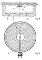
- the protection and, if appropriate, for the isolation of the resistance track 23, to apply a glass or glass ceramic layer over the same.
- the application is again by means of screen printing technique.
- This protective, insulating insulating layer 26 is then fixed by baking, at or just below the melting temperature of the applied glass or ceramic frit on the substrate 23 carrying the resistance path.
- Electrical contact between the contact 41 and the resistance path 23 can be made via a metal strip 42 that is connected by the contact 41 via a slot in the ceramic body 22 with the resistance path 23 (see Fig. 10 ).
- a resilient contact 41 a may be connected via a rivet 43 with the ceramic body 22, wherein the resistance path 23 is then clamped between the resilient contact 41 a and the ceramic body 22.
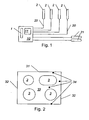
- Fig.2 shows a ceramic hob 33 with heating 3.
- the number, shape and arrangement of the heating areas 3 on a hob can hereby vary as desired.
- Each heating area is assigned a sensor 2 (in Fig. 2 not shown), which is schematically shown in FIG Fig. 1 are shown.
- the measuring sensors 2 are electrically connected via lines 20 to a computing unit 10.
- the sensors 2 are not calibrated for the time being and may be designed, for example, as resistance sensors.
- a standard measuring sensor 1 is furthermore arranged, for example a platinum resistance sensor with known temperature-dependent resistance Rs (T), in particular a PT-100 or PT-1000 sensor.
- the standard sensor 1 supplies the respective current temperature value in the area of the arithmetic unit 10.
- Further measuring sensors 21 can also be arranged in areas 34 outside the heating areas 3.
- the calibration of the individual sensors takes place in such a way that in a first step, the temperature is measured in the cooktop in thermal equilibrium with the aid of the calibrated sensor. In a further step, the resistances of the uncalibrated sensors associated with this temperature are measured. From this information can then easily a calibration factor or the resistance of the sensors at a defined temperature, preferably 25 ° C, determined and then stored.
- the measuring sensors 2 are resistance sensors, in particular platinum resistance sensors, which have a resistance R (T), which is dependent on the respective temperature T and in each case has known electrical resistance coefficients.
- a calibration of the probe 2 is carried out in the temperature equilibrium, in particular before the first start of the heating areas 3, ie substantially at room temperature, because then the temperature at the probes 2 is naturally equal to that of the standard probe 1.
- Corresponding calibration values for the measuring sensors 2 are advantageously stored in a memory unit 11 of the arithmetic unit 10.
- the determination of R 0 is required as a calibration value.
- the objective method is carried out in the temperature equilibrium, preferably before the first start-up of the heating areas 3, because only in the temperature equilibrium can it be assumed that all the sensors 2, 21 and the standard sensor 1 have the same temperature.
- known temperature profiles can also be utilized. So there are, for example, characteristic temperature profiles during the cooling of a heating area 3 after its shutdown. Furthermore, however, the temperature of a sensor 2 of a heating region 3, which is not in operation, according to a characteristic course increase when adjacent heating areas 3 are in operation. Further characteristic temperature profiles as a function of the operating state of adjacent heating areas 3 can also be registered by further measuring sensors 21 outside of heating areas 3. Such characteristic temperature profiles as a function of location, operating state of adjacent heating areas 3 and time can be described as so-called characteristics fields and stored in the memory unit 11.
- the temperature in arbitrary regions 34 for example on the rear wall 31 or sidewalls 32 can therefore be determined by the arithmetic unit 10 from the temperatures at sensors 2, 21 at defined intervals.
- a limit T max be given, when it reaches a process such as an alarm, a switching operation or a
- Control process is triggered. For example, it can be ensured that safety-critical temperatures in certain areas are avoided.
- the current temperature at as many points of the ceramic hob it is advantageous to know the current temperature at as many points of the ceramic hob as possible.
- the calibration of the individual sensors takes place in such a way that in a first step, the temperature is measured in the cooktop in thermal equilibrium with the aid of the calibrated sensor. In a further step, the resistances of the uncalibrated sensors associated with this temperature are measured. From this information can then easily a calibration factor or the resistance of the sensors at a defined temperature, preferably 25 ° C, determined and then stored.
Landscapes
- Physics & Mathematics (AREA)
- General Physics & Mathematics (AREA)
- Control Of Resistance Heating (AREA)
- Measuring Fluid Pressure (AREA)
- Glass Compositions (AREA)
- Indication And Recording Devices For Special Purposes And Tariff Metering Devices (AREA)
- Investigating Or Analyzing Materials Using Thermal Means (AREA)
Claims (4)
- Capteur (2) destiné à déterminer la valeur moyenne de la température d'une surface de chauffe (3) d'une plaque vitrocéramique chauffée par une source de chaleur, le capteur (2) pouvant venir se disposer entre la source de chaleur et la plaque vitrocéramique, le capteur (2) comprenant un corps en céramique (22) et une bande résistive (23) dépendant de la température, appliquée sur le corps en céramique (22), qui peut venir se disposer à distance de la surface de chauffe (3), la bande résistive (23) étant reliée par conduction, à l'extérieur de la zone dans laquelle la température doit être enregistrée, avec des surfaces de connexion d'une connexion électrique externe (41a), caractérisé en ce que la longueur de la bande résistive (23) s'élève à au moins 200 mm, en ce que la bande résistive (23) est réalisée, dans une zone (23a), qui peut être séparée clairement de la connexion électrique (41a), de la bande résistive entre la connexion électrique (41a) et une zone de la bande résistive (23) sensible à la température, destinée à l'enregistrement de la température, avec une section transversale supérieure, en particulier avec une section transversale au moins doublée, et en ce qu'on prévoit, pour la connexion (41a) de la bande résistive (23), des éléments de connexion constitués d'une matière possédant une élasticité analogue à celle d'un ressort, qui sont rivetés au corps en céramique (22) et qui sont munis d'évidements tournés vers un bande résistive (23), si bien que la bande résistive (23) est serrée, dans ses zones (23a) de section transversale supérieure, respectivement entre la connexion (41a) et le corps en céramique (22).
- Capteur selon la revendication 1, caractérisé en ce que le corps en céramique (22), pour améliorer la stabilité mécanique, manifeste un rétrécissement dans la zone de son extrémité qui se détourne de la connexion (41 a).
- Capteur selon la revendication 1 ou 2, caractérisé en ce que le corps en céramique (22) présente, dans la zone de la connexion (41a), une zone élargie, la transition avec la zone restante plus étroite du corps en céramique (22) présentant de préférence une concavité.
- Capteur selon l'une quelconque des revendications 1 à 3, caractérisé en ce que la bande résistive (23) du capteur (2) est isolée avec une couche de passivation fermée (26).
Priority Applications (7)
| Application Number | Priority Date | Filing Date | Title |
|---|---|---|---|
| EP04004153.5A EP1568980B2 (fr) | 2004-02-24 | 2004-02-24 | Capteur de température |
| DE502004004371T DE502004004371D1 (de) | 2004-02-24 | 2004-02-24 | Temperaturmessfühler |
| EP05018737A EP1619485B8 (fr) | 2004-02-24 | 2004-02-24 | Capteur de température |
| AT04004153T ATE332493T1 (de) | 2004-02-24 | 2004-02-24 | Temperaturmessfühler |
| AT05018737T ATE367573T1 (de) | 2004-02-24 | 2004-02-24 | Temperaturmessfühler |
| DE502004000918T DE502004000918D1 (de) | 2004-02-24 | 2004-02-24 | Temperaturmessfühler |
| US11/065,435 US7214909B2 (en) | 2004-02-24 | 2005-02-24 | Temperature sensor |
Applications Claiming Priority (1)
| Application Number | Priority Date | Filing Date | Title |
|---|---|---|---|
| EP04004153.5A EP1568980B2 (fr) | 2004-02-24 | 2004-02-24 | Capteur de température |
Related Child Applications (2)
| Application Number | Title | Priority Date | Filing Date |
|---|---|---|---|
| EP05018737A Division EP1619485B8 (fr) | 2004-02-24 | 2004-02-24 | Capteur de température |
| EP05018737.6 Division-Into | 2005-08-30 |
Publications (3)
| Publication Number | Publication Date |
|---|---|
| EP1568980A1 EP1568980A1 (fr) | 2005-08-31 |
| EP1568980B1 EP1568980B1 (fr) | 2006-07-05 |
| EP1568980B2 true EP1568980B2 (fr) | 2013-08-14 |
Family
ID=34745870
Family Applications (2)
| Application Number | Title | Priority Date | Filing Date |
|---|---|---|---|
| EP05018737A Expired - Lifetime EP1619485B8 (fr) | 2004-02-24 | 2004-02-24 | Capteur de température |
| EP04004153.5A Expired - Lifetime EP1568980B2 (fr) | 2004-02-24 | 2004-02-24 | Capteur de température |
Family Applications Before (1)
| Application Number | Title | Priority Date | Filing Date |
|---|---|---|---|
| EP05018737A Expired - Lifetime EP1619485B8 (fr) | 2004-02-24 | 2004-02-24 | Capteur de température |
Country Status (4)
| Country | Link |
|---|---|
| US (1) | US7214909B2 (fr) |
| EP (2) | EP1619485B8 (fr) |
| AT (2) | ATE332493T1 (fr) |
| DE (2) | DE502004000918D1 (fr) |
Families Citing this family (15)
| Publication number | Priority date | Publication date | Assignee | Title |
|---|---|---|---|---|
| AT8257U1 (de) * | 2005-04-19 | 2006-04-15 | Electrovac | Messfühleranordnung |
| DE102005040041B3 (de) * | 2005-08-23 | 2006-10-19 | Miele & Cie. Kg | Glaskeramikkochfeld mit wenigstens einem Kochfeldbereich |
| DE102006010107A1 (de) * | 2006-03-01 | 2007-09-06 | E.G.O. Elektro-Gerätebau GmbH | Verfahren und Vorrichtung zur Erkennung eines an eine Steuerung angeschlossenen Temperatursensors |
| GB2446414A (en) * | 2007-02-06 | 2008-08-13 | Thorn Security | A Detector |
| WO2008117909A1 (fr) * | 2007-03-28 | 2008-10-02 | Lg Electronics Inc. | Dispositif de détection de la chaleur, appareil de cuisson utilisant ledit dispositif et procédé de régulation de l'appareil de cuisson |
| KR101261647B1 (ko) * | 2007-03-28 | 2013-05-06 | 엘지전자 주식회사 | 가열조리기기의 제어방법 |
| DE102007046900C5 (de) | 2007-09-28 | 2018-07-26 | Heraeus Sensor Technology Gmbh | Hochtemperatursensor und ein Verfahren zu dessen Herstellung |
| IT1393070B1 (it) * | 2008-10-24 | 2012-04-11 | Worgas Bruciatori Srl | Termocoppia speciale per bruciatori |
| EP2467345A1 (fr) * | 2009-08-17 | 2012-06-27 | BSH Bosch und Siemens Hausgeräte GmbH | Plaque de couverture d'appareil ménager comportant une plaque support au moins semi-transparente, appareil ménager destiné à la préparation d'aliments et procédé de fabrication d'une plaque de couverture d'appareil ménager |
| DE102013110046B4 (de) | 2013-09-12 | 2023-03-16 | Endress+Hauser Conducta Gmbh+Co. Kg | Verfahren und elektrische Schaltung zum Bestimmen einer physikalischen und/oder chemischen temperaturabhängigen Prozessgröße |
| CN104501988B (zh) * | 2014-12-16 | 2017-09-08 | 南京时恒电子科技有限公司 | 一种宽温区高精度ntc温度传感器的制作方法 |
| US20160227609A1 (en) * | 2015-01-30 | 2016-08-04 | Schott Corporation | Multi function glass or glass-ceramic cooktop system and method of cooking thereon |
| CN104655304A (zh) * | 2015-03-01 | 2015-05-27 | 吴传涛 | 一种工业直燃炉炉温检测探头 |
| CN107889300A (zh) * | 2016-09-29 | 2018-04-06 | 浙江久康电器有限公司 | 插接式红外线电热炉盘及装用该电热炉盘的电加热灶 |
| DE102017115946A1 (de) * | 2017-07-14 | 2019-01-17 | Borgwarner Ludwigsburg Gmbh | Verfahren zum Regeln der Temperatur einer Glühkerze |
Citations (8)
| Publication number | Priority date | Publication date | Assignee | Title |
|---|---|---|---|---|
| GB1415644A (en) † | 1971-11-18 | 1975-11-26 | Johnson Matthey Co Ltd | Resistance thermometer element |
| GB2006521A (en) † | 1977-09-13 | 1979-05-02 | Johnson Matthey Co Ltd | Resistance thermometers |
| US4371861A (en) † | 1980-12-11 | 1983-02-01 | Honeywell Inc. | Ni-fe thin-film temperature sensor |
| US4708769A (en) † | 1984-08-16 | 1987-11-24 | Robert Bosch Gmbh | Temperature dependent electric resistor probe and a method of making the same |
| EP0437356A2 (fr) † | 1990-01-11 | 1991-07-17 | General Electric Company | Capteurs de températures |
| US5430428A (en) † | 1991-02-15 | 1995-07-04 | Siemens Aktiengesellschaft | High-temperature sensor made of metal of the platinum group |
| US5823680A (en) † | 1993-12-27 | 1998-10-20 | Ngk Insulators, Ltd. | Temperature sensor |
| US20030072352A1 (en) † | 2001-10-15 | 2003-04-17 | Heraeus Sensor-Nite Gmbh | Temperature sensor with a sensor element and use thereof |
Family Cites Families (14)
| Publication number | Priority date | Publication date | Assignee | Title |
|---|---|---|---|---|
| US1697954A (en) * | 1925-10-10 | 1929-01-08 | Shakeproof Lock Washer Co | Electrical connecter |
| US3892947A (en) * | 1974-02-27 | 1975-07-01 | Donnelly Mirrors Inc | Electrically heated panel with anti-shock conductive strips |
| EP0063264B1 (fr) | 1980-04-16 | 1984-12-12 | Kabushiki Kaisha Kirk | Procédé de réalisation d'un élément résistif à couche mince en platine sensible à la temperature |
| DE3100852A1 (de) | 1981-01-14 | 1982-08-12 | Draloric Electronic GmbH, 6000 Frankfurt | Elektrisches bauelement |
| DE8109131U1 (de) * | 1981-03-27 | 1981-08-20 | E.G.O. Elektro-Geräte Blanc u. Fischer, 7519 Oberderdingen | Temperaturfuehlanordnung fuer elektrische strahlheizkoerper |
| GB2103910B (en) * | 1981-08-08 | 1985-08-21 | Micropore International Ltd | Improvements in electric cookers incorporating radiant heaters |
| US4815198A (en) * | 1985-04-29 | 1989-03-28 | Ford Motor Company | Method for making a part of an electrically heated windshield assembly |
| US5288973A (en) * | 1991-12-28 | 1994-02-22 | Rohm Co., Ltd. | Heater for sheet material |
| EP0806886B1 (fr) * | 1996-05-11 | 2005-01-26 | AEG Hausgeräte GmbH | Procédé et dispositif pour la thermométrie à un réchaud avec un capteur à piste conductive de température |
| DE19632057C2 (de) * | 1996-08-09 | 2000-06-21 | Schott Glas | Verfahren zum Kalibrieren von Temperaturmeßwiderständen auf Trägern aus Glas, Glaskeramik oder dergleichen |
| DE19925367A1 (de) * | 1998-07-09 | 2000-01-13 | Electrovac | Temperatursensor |
| DE19901184C1 (de) * | 1999-01-14 | 2000-10-26 | Sensotherm Temperatursensorik | Platintemperatursensor und Verfahren zur Herstellung desselben |
| US6588931B2 (en) * | 2000-12-07 | 2003-07-08 | Delphi Technologies, Inc. | Temperature sensor with flexible circuit substrate |
| GB0116884D0 (en) * | 2001-07-11 | 2001-09-05 | Ceramaspeed Ltd | Temperature sensor assembly and radiant electric heater incorporating the same |
-
2004
- 2004-02-24 AT AT04004153T patent/ATE332493T1/de active
- 2004-02-24 DE DE502004000918T patent/DE502004000918D1/de not_active Expired - Lifetime
- 2004-02-24 EP EP05018737A patent/EP1619485B8/fr not_active Expired - Lifetime
- 2004-02-24 EP EP04004153.5A patent/EP1568980B2/fr not_active Expired - Lifetime
- 2004-02-24 DE DE502004004371T patent/DE502004004371D1/de not_active Expired - Lifetime
- 2004-02-24 AT AT05018737T patent/ATE367573T1/de active
-
2005
- 2005-02-24 US US11/065,435 patent/US7214909B2/en not_active Expired - Fee Related
Patent Citations (8)
| Publication number | Priority date | Publication date | Assignee | Title |
|---|---|---|---|---|
| GB1415644A (en) † | 1971-11-18 | 1975-11-26 | Johnson Matthey Co Ltd | Resistance thermometer element |
| GB2006521A (en) † | 1977-09-13 | 1979-05-02 | Johnson Matthey Co Ltd | Resistance thermometers |
| US4371861A (en) † | 1980-12-11 | 1983-02-01 | Honeywell Inc. | Ni-fe thin-film temperature sensor |
| US4708769A (en) † | 1984-08-16 | 1987-11-24 | Robert Bosch Gmbh | Temperature dependent electric resistor probe and a method of making the same |
| EP0437356A2 (fr) † | 1990-01-11 | 1991-07-17 | General Electric Company | Capteurs de températures |
| US5430428A (en) † | 1991-02-15 | 1995-07-04 | Siemens Aktiengesellschaft | High-temperature sensor made of metal of the platinum group |
| US5823680A (en) † | 1993-12-27 | 1998-10-20 | Ngk Insulators, Ltd. | Temperature sensor |
| US20030072352A1 (en) † | 2001-10-15 | 2003-04-17 | Heraeus Sensor-Nite Gmbh | Temperature sensor with a sensor element and use thereof |
Also Published As
| Publication number | Publication date |
|---|---|
| US7214909B2 (en) | 2007-05-08 |
| EP1619485B8 (fr) | 2007-10-03 |
| DE502004000918D1 (de) | 2006-08-17 |
| US20050184044A1 (en) | 2005-08-25 |
| EP1568980B1 (fr) | 2006-07-05 |
| EP1619485B1 (fr) | 2007-07-18 |
| ATE332493T1 (de) | 2006-07-15 |
| ATE367573T1 (de) | 2007-08-15 |
| DE502004004371D1 (de) | 2007-08-30 |
| EP1619485A1 (fr) | 2006-01-25 |
| EP1568980A1 (fr) | 2005-08-31 |
Similar Documents
| Publication | Publication Date | Title |
|---|---|---|
| EP1568980B2 (fr) | Capteur de température | |
| DE4022845C2 (fr) | ||
| EP1989922B1 (fr) | Procédé et dispositif de reconaissance d'une sonde de température raccordé à une commande | |
| DE102004022206B4 (de) | Sensor und Sensoranordnung zur Messung der Wärmeleitfähigkeit einer Probe | |
| DE69117374T2 (de) | SiC-Dünnschichtthermistor und Verfahren und Herstellungsverfahren. | |
| EP1936279B1 (fr) | Procédé et dispositif pour la détermination dans le temps de la quantité de vapeur emise d'un produit à cuire dans une chambre de cuisson pendant la cuisson | |
| EP1152639B1 (fr) | Unité de chauffage électrique, particulièrement destiné à des milieux liquides | |
| DE202010005756U1 (de) | Elektronisches Bauelement, insbesondere Stromsensor | |
| DE2644883B2 (de) | Feuchtigkeitsempfindliche Widerstandsvorrichtung | |
| DE102013200277A1 (de) | Heizeinrichtung und Verfahren zur Temperaturmessung an der Heizeinrichtung | |
| EP2145166B1 (fr) | Thermomètre à résistance | |
| DE19647985A1 (de) | Verfahren und Vorrichtung zum Bestimmen der Güte des Bodens von Kochgeschirr | |
| DE2139828C3 (de) | Temperaturmeßwiderstand mit großer Temperaturwechselbeständigkeit aus Glaskeramik | |
| WO2014095425A2 (fr) | Élément capteur, thermomètre et procédé de détermination d'une température | |
| EP0823620B1 (fr) | Méthode pour calibrer des résistances de mesure de la température sur un support en verre, en céramique de verre ou analogue | |
| EP3404405A1 (fr) | Capteur de détermination de paramètres de gaz | |
| DE19646826C2 (de) | Vorrichtung zur Temperaturmessung an Kochstellen | |
| DE69814877T2 (de) | Elektrischer flussigkeitsheizvorrichtung | |
| WO2009027042A1 (fr) | Dispositif de chauffage, procédé pour faire fonctionner un dispositif de chauffage et appareil de chauffage électrique appartenant à un tel dispositif de chauffage | |
| EP1715316B1 (fr) | Dispositif de sonde | |
| DE102013206406B4 (de) | Raumklimamessgerät und Regelungseinrichtung | |
| DE10206045B4 (de) | Quasistationäres Verfahren zur Messung der Wärmeleitfähigkeit | |
| DE19707664C2 (de) | Vorrichtung und Verfahren zur Steuerung oder Regelung der Temperatur von beheizten Flächen | |
| DE1943748A1 (de) | Heiz- und Temperaturmessgeraet | |
| EP0806886B1 (fr) | Procédé et dispositif pour la thermométrie à un réchaud avec un capteur à piste conductive de température |
Legal Events
| Date | Code | Title | Description |
|---|---|---|---|
| PUAI | Public reference made under article 153(3) epc to a published international application that has entered the european phase |
Free format text: ORIGINAL CODE: 0009012 |
|
| 17P | Request for examination filed |
Effective date: 20050404 |
|
| AK | Designated contracting states |
Kind code of ref document: A1 Designated state(s): AT BE BG CH CY CZ DE DK EE ES FI FR GB GR HU IE IT LI LU MC NL PT RO SE SI SK TR |
|
| AX | Request for extension of the european patent |
Extension state: AL LT LV MK |
|
| GRAP | Despatch of communication of intention to grant a patent |
Free format text: ORIGINAL CODE: EPIDOSNIGR1 |
|
| AKX | Designation fees paid |
Designated state(s): AT BE BG CH CY CZ DE DK EE ES FI FR GB GR HU IE IT LI LU MC NL PT RO SE SI SK TR |
|
| GRAS | Grant fee paid |
Free format text: ORIGINAL CODE: EPIDOSNIGR3 |
|
| GRAA | (expected) grant |
Free format text: ORIGINAL CODE: 0009210 |
|
| AK | Designated contracting states |
Kind code of ref document: B1 Designated state(s): AT BE BG CH CY CZ DE DK EE ES FI FR GB GR HU IE IT LI LU MC NL PT RO SE SI SK TR |
|
| PG25 | Lapsed in a contracting state [announced via postgrant information from national office to epo] |
Ref country code: IT Free format text: LAPSE BECAUSE OF FAILURE TO SUBMIT A TRANSLATION OF THE DESCRIPTION OR TO PAY THE FEE WITHIN THE PRESCRIBED TIME-LIMIT;WARNING: LAPSES OF ITALIAN PATENTS WITH EFFECTIVE DATE BEFORE 2007 MAY HAVE OCCURRED AT ANY TIME BEFORE 2007. THE CORRECT EFFECTIVE DATE MAY BE DIFFERENT FROM THE ONE RECORDED. Effective date: 20060705 Ref country code: NL Free format text: LAPSE BECAUSE OF FAILURE TO SUBMIT A TRANSLATION OF THE DESCRIPTION OR TO PAY THE FEE WITHIN THE PRESCRIBED TIME-LIMIT Effective date: 20060705 Ref country code: FI Free format text: LAPSE BECAUSE OF FAILURE TO SUBMIT A TRANSLATION OF THE DESCRIPTION OR TO PAY THE FEE WITHIN THE PRESCRIBED TIME-LIMIT Effective date: 20060705 Ref country code: CZ Free format text: LAPSE BECAUSE OF FAILURE TO SUBMIT A TRANSLATION OF THE DESCRIPTION OR TO PAY THE FEE WITHIN THE PRESCRIBED TIME-LIMIT Effective date: 20060705 Ref country code: IE Free format text: LAPSE BECAUSE OF FAILURE TO SUBMIT A TRANSLATION OF THE DESCRIPTION OR TO PAY THE FEE WITHIN THE PRESCRIBED TIME-LIMIT Effective date: 20060705 Ref country code: RO Free format text: LAPSE BECAUSE OF FAILURE TO SUBMIT A TRANSLATION OF THE DESCRIPTION OR TO PAY THE FEE WITHIN THE PRESCRIBED TIME-LIMIT Effective date: 20060705 Ref country code: SK Free format text: LAPSE BECAUSE OF FAILURE TO SUBMIT A TRANSLATION OF THE DESCRIPTION OR TO PAY THE FEE WITHIN THE PRESCRIBED TIME-LIMIT Effective date: 20060705 Ref country code: SI Free format text: LAPSE BECAUSE OF FAILURE TO SUBMIT A TRANSLATION OF THE DESCRIPTION OR TO PAY THE FEE WITHIN THE PRESCRIBED TIME-LIMIT Effective date: 20060705 |
|
| REG | Reference to a national code |
Ref country code: GB Ref legal event code: FG4D Free format text: NOT ENGLISH |
|
| REG | Reference to a national code |
Ref country code: CH Ref legal event code: EP |
|
| REG | Reference to a national code |
Ref country code: IE Ref legal event code: FG4D Free format text: LANGUAGE OF EP DOCUMENT: GERMAN |
|
| REF | Corresponds to: |
Ref document number: 502004000918 Country of ref document: DE Date of ref document: 20060817 Kind code of ref document: P |
|
| PG25 | Lapsed in a contracting state [announced via postgrant information from national office to epo] |
Ref country code: BG Free format text: LAPSE BECAUSE OF FAILURE TO SUBMIT A TRANSLATION OF THE DESCRIPTION OR TO PAY THE FEE WITHIN THE PRESCRIBED TIME-LIMIT Effective date: 20061005 Ref country code: DK Free format text: LAPSE BECAUSE OF FAILURE TO SUBMIT A TRANSLATION OF THE DESCRIPTION OR TO PAY THE FEE WITHIN THE PRESCRIBED TIME-LIMIT Effective date: 20061005 Ref country code: SE Free format text: LAPSE BECAUSE OF FAILURE TO SUBMIT A TRANSLATION OF THE DESCRIPTION OR TO PAY THE FEE WITHIN THE PRESCRIBED TIME-LIMIT Effective date: 20061005 |
|
| RAP2 | Party data changed (patent owner data changed or rights of a patent transferred) |
Owner name: ELECTROVAC AG |
|
| PG25 | Lapsed in a contracting state [announced via postgrant information from national office to epo] |
Ref country code: ES Free format text: LAPSE BECAUSE OF FAILURE TO SUBMIT A TRANSLATION OF THE DESCRIPTION OR TO PAY THE FEE WITHIN THE PRESCRIBED TIME-LIMIT Effective date: 20061016 |
|
| GBT | Gb: translation of ep patent filed (gb section 77(6)(a)/1977) |
Effective date: 20061020 |
|
| NLT2 | Nl: modifications (of names), taken from the european patent patent bulletin |
Owner name: ELECTROVAC AG Effective date: 20061011 |
|
| NLV1 | Nl: lapsed or annulled due to failure to fulfill the requirements of art. 29p and 29m of the patents act | ||
| PG25 | Lapsed in a contracting state [announced via postgrant information from national office to epo] |
Ref country code: PT Free format text: LAPSE BECAUSE OF FAILURE TO SUBMIT A TRANSLATION OF THE DESCRIPTION OR TO PAY THE FEE WITHIN THE PRESCRIBED TIME-LIMIT Effective date: 20061205 |
|
| REG | Reference to a national code |
Ref country code: IE Ref legal event code: FD4D |
|
| PG25 | Lapsed in a contracting state [announced via postgrant information from national office to epo] |
Ref country code: MC Free format text: LAPSE BECAUSE OF NON-PAYMENT OF DUE FEES Effective date: 20070228 |
|
| PLBI | Opposition filed |
Free format text: ORIGINAL CODE: 0009260 |
|
| PLAX | Notice of opposition and request to file observation + time limit sent |
Free format text: ORIGINAL CODE: EPIDOSNOBS2 |
|
| EN | Fr: translation not filed | ||
| 26 | Opposition filed |
Opponent name: CERAMASPEED LIMITED Effective date: 20070403 |
|
| PLBB | Reply of patent proprietor to notice(s) of opposition received |
Free format text: ORIGINAL CODE: EPIDOSNOBS3 |
|
| BERE | Be: lapsed |
Owner name: ELECTROVAC, FABRIKATION ELEKTROTECHNISCHER SPEZIA Effective date: 20070228 |
|
| PG25 | Lapsed in a contracting state [announced via postgrant information from national office to epo] |
Ref country code: BE Free format text: LAPSE BECAUSE OF NON-PAYMENT OF DUE FEES Effective date: 20070228 |
|
| PG25 | Lapsed in a contracting state [announced via postgrant information from national office to epo] |
Ref country code: GR Free format text: LAPSE BECAUSE OF FAILURE TO SUBMIT A TRANSLATION OF THE DESCRIPTION OR TO PAY THE FEE WITHIN THE PRESCRIBED TIME-LIMIT Effective date: 20061006 Ref country code: FR Free format text: LAPSE BECAUSE OF FAILURE TO SUBMIT A TRANSLATION OF THE DESCRIPTION OR TO PAY THE FEE WITHIN THE PRESCRIBED TIME-LIMIT Effective date: 20070511 |
|
| PG25 | Lapsed in a contracting state [announced via postgrant information from national office to epo] |
Ref country code: EE Free format text: LAPSE BECAUSE OF FAILURE TO SUBMIT A TRANSLATION OF THE DESCRIPTION OR TO PAY THE FEE WITHIN THE PRESCRIBED TIME-LIMIT Effective date: 20060705 |
|
| REG | Reference to a national code |
Ref country code: CH Ref legal event code: PL |
|
| PG25 | Lapsed in a contracting state [announced via postgrant information from national office to epo] |
Ref country code: LI Free format text: LAPSE BECAUSE OF NON-PAYMENT OF DUE FEES Effective date: 20080229 Ref country code: CH Free format text: LAPSE BECAUSE OF NON-PAYMENT OF DUE FEES Effective date: 20080229 |
|
| PG25 | Lapsed in a contracting state [announced via postgrant information from national office to epo] |
Ref country code: FR Free format text: LAPSE BECAUSE OF FAILURE TO SUBMIT A TRANSLATION OF THE DESCRIPTION OR TO PAY THE FEE WITHIN THE PRESCRIBED TIME-LIMIT Effective date: 20060705 |
|
| PLAB | Opposition data, opponent's data or that of the opponent's representative modified |
Free format text: ORIGINAL CODE: 0009299OPPO |
|
| PG25 | Lapsed in a contracting state [announced via postgrant information from national office to epo] |
Ref country code: CY Free format text: LAPSE BECAUSE OF FAILURE TO SUBMIT A TRANSLATION OF THE DESCRIPTION OR TO PAY THE FEE WITHIN THE PRESCRIBED TIME-LIMIT Effective date: 20060705 Ref country code: LU Free format text: LAPSE BECAUSE OF NON-PAYMENT OF DUE FEES Effective date: 20070224 |
|
| PG25 | Lapsed in a contracting state [announced via postgrant information from national office to epo] |
Ref country code: TR Free format text: LAPSE BECAUSE OF FAILURE TO SUBMIT A TRANSLATION OF THE DESCRIPTION OR TO PAY THE FEE WITHIN THE PRESCRIBED TIME-LIMIT Effective date: 20060705 Ref country code: HU Free format text: LAPSE BECAUSE OF FAILURE TO SUBMIT A TRANSLATION OF THE DESCRIPTION OR TO PAY THE FEE WITHIN THE PRESCRIBED TIME-LIMIT Effective date: 20070106 |
|
| PGFP | Annual fee paid to national office [announced via postgrant information from national office to epo] |
Ref country code: IT Payment date: 20110228 Year of fee payment: 8 |
|
| REG | Reference to a national code |
Ref country code: DE Ref legal event code: R082 Ref document number: 502004000918 Country of ref document: DE Representative=s name: GRAF GLUECK HABERSACK KRITZENBERGER, DE |
|
| REG | Reference to a national code |
Ref country code: DE Ref legal event code: R082 Ref document number: 502004000918 Country of ref document: DE Representative=s name: GRAF GLUECK KRITZENBERGER, DE Effective date: 20120314 Ref country code: DE Ref legal event code: R081 Ref document number: 502004000918 Country of ref document: DE Owner name: REITER, WERNER, AT Free format text: FORMER OWNER: ELECTROVAC AG, KLOSTERNEUBURG, AT Effective date: 20120314 Ref country code: DE Ref legal event code: R082 Ref document number: 502004000918 Country of ref document: DE Representative=s name: GLUECK - KRITZENBERGER PATENTANWAELTE PARTGMBB, DE Effective date: 20120314 |
|
| REG | Reference to a national code |
Ref country code: GB Ref legal event code: 732E Free format text: REGISTERED BETWEEN 20120607 AND 20120613 |
|
| REG | Reference to a national code |
Ref country code: AT Ref legal event code: PC Ref document number: 332493 Country of ref document: AT Kind code of ref document: T Owner name: WERNER REITER, AT Effective date: 20120518 |
|
| PUAH | Patent maintained in amended form |
Free format text: ORIGINAL CODE: 0009272 |
|
| STAA | Information on the status of an ep patent application or granted ep patent |
Free format text: STATUS: PATENT MAINTAINED AS AMENDED |
|
| 27A | Patent maintained in amended form |
Effective date: 20130814 |
|
| AK | Designated contracting states |
Kind code of ref document: B2 Designated state(s): AT BE BG CH CY CZ DE DK EE ES FI FR GB GR HU IE IT LI LU MC NL PT RO SE SI SK TR |
|
| REG | Reference to a national code |
Ref country code: DE Ref legal event code: R102 Ref document number: 502004000918 Country of ref document: DE Effective date: 20130814 |
|
| PG25 | Lapsed in a contracting state [announced via postgrant information from national office to epo] |
Ref country code: IT Free format text: LAPSE BECAUSE OF NON-PAYMENT OF DUE FEES Effective date: 20120224 |
|
| PGFP | Annual fee paid to national office [announced via postgrant information from national office to epo] |
Ref country code: AT Payment date: 20140212 Year of fee payment: 11 |
|
| PGFP | Annual fee paid to national office [announced via postgrant information from national office to epo] |
Ref country code: GB Payment date: 20140218 Year of fee payment: 11 |
|
| PGFP | Annual fee paid to national office [announced via postgrant information from national office to epo] |
Ref country code: DE Payment date: 20150227 Year of fee payment: 12 |
|
| REG | Reference to a national code |
Ref country code: AT Ref legal event code: MM01 Ref document number: 332493 Country of ref document: AT Kind code of ref document: T Effective date: 20150224 |
|
| GBPC | Gb: european patent ceased through non-payment of renewal fee |
Effective date: 20150224 |
|
| PG25 | Lapsed in a contracting state [announced via postgrant information from national office to epo] |
Ref country code: AT Free format text: LAPSE BECAUSE OF NON-PAYMENT OF DUE FEES Effective date: 20150224 |
|
| PG25 | Lapsed in a contracting state [announced via postgrant information from national office to epo] |
Ref country code: GB Free format text: LAPSE BECAUSE OF NON-PAYMENT OF DUE FEES Effective date: 20150224 |
|
| REG | Reference to a national code |
Ref country code: DE Ref legal event code: R119 Ref document number: 502004000918 Country of ref document: DE |
|
| PG25 | Lapsed in a contracting state [announced via postgrant information from national office to epo] |
Ref country code: DE Free format text: LAPSE BECAUSE OF NON-PAYMENT OF DUE FEES Effective date: 20160901 |