EP1715145A1 - Carter d'huile et moteur a combustion - Google Patents
Carter d'huile et moteur a combustion Download PDFInfo
- Publication number
- EP1715145A1 EP1715145A1 EP06300373A EP06300373A EP1715145A1 EP 1715145 A1 EP1715145 A1 EP 1715145A1 EP 06300373 A EP06300373 A EP 06300373A EP 06300373 A EP06300373 A EP 06300373A EP 1715145 A1 EP1715145 A1 EP 1715145A1
- Authority
- EP
- European Patent Office
- Prior art keywords
- oil
- tank
- oil pan
- flange
- screw
- Prior art date
- Legal status (The legal status is an assumption and is not a legal conclusion. Google has not performed a legal analysis and makes no representation as to the accuracy of the status listed.)
- Granted
Links
Images
Classifications
-
- F—MECHANICAL ENGINEERING; LIGHTING; HEATING; WEAPONS; BLASTING
- F01—MACHINES OR ENGINES IN GENERAL; ENGINE PLANTS IN GENERAL; STEAM ENGINES
- F01M—LUBRICATING OF MACHINES OR ENGINES IN GENERAL; LUBRICATING INTERNAL COMBUSTION ENGINES; CRANKCASE VENTILATING
- F01M11/00—Component parts, details or accessories, not provided for in, or of interest apart from, groups F01M1/00 - F01M9/00
- F01M11/0004—Oilsumps
-
- F—MECHANICAL ENGINEERING; LIGHTING; HEATING; WEAPONS; BLASTING
- F01—MACHINES OR ENGINES IN GENERAL; ENGINE PLANTS IN GENERAL; STEAM ENGINES
- F01M—LUBRICATING OF MACHINES OR ENGINES IN GENERAL; LUBRICATING INTERNAL COMBUSTION ENGINES; CRANKCASE VENTILATING
- F01M11/00—Component parts, details or accessories, not provided for in, or of interest apart from, groups F01M1/00 - F01M9/00
- F01M11/0004—Oilsumps
- F01M2011/0054—Fastening to the cylinder block
-
- F—MECHANICAL ENGINEERING; LIGHTING; HEATING; WEAPONS; BLASTING
- F01—MACHINES OR ENGINES IN GENERAL; ENGINE PLANTS IN GENERAL; STEAM ENGINES
- F01M—LUBRICATING OF MACHINES OR ENGINES IN GENERAL; LUBRICATING INTERNAL COMBUSTION ENGINES; CRANKCASE VENTILATING
- F01M11/00—Component parts, details or accessories, not provided for in, or of interest apart from, groups F01M1/00 - F01M9/00
- F01M11/0004—Oilsumps
- F01M2011/0066—Oilsumps with passages in the wall, e.g. for axles or fluid passages
Definitions
- the present invention relates to an oil sump and a combustion engine of a motor vehicle.
- an oil pan of the type comprising a tank defining, on the one hand, an oil receiving volume, and, on the other hand, an upper opening bordered by a flange integral with the tank for mounting on a complementary member of a combustion engine of a motor vehicle.
- the increase in the spacing between two oil changes is sought.
- the car manufacturers aim to allow vehicles to perform at least 30000 kilometers between two oil changes.
- the invention aims to overcome this problem by providing an oil sump whose reception volume makes it possible to achieve the objectives mentioned above.
- the subject of the invention is an oil pan of the aforementioned type, characterized in that the vessel has an outgrowth such that the oil receiving volume projects laterally with respect to the perpendicular axis direction cylinder. at the oil level at rest in the housing and based on an outside contour of the flange.
- the tank is enlarged in its horizontal direction, which makes it possible to obtain a larger reception volume than in the state of the art.
- this solution has the advantage of not increasing the vertical size of the oil sump, which makes it compatible with future standards and regulations dealing with shocks with a pedestrian and aimed at limiting the vertical size of the engine.
- the flange carries fastening means on the complementary member, the protrusion covers these fixing means and access means to the fastening means are formed in the tank
- the oil sump according to the invention can be mounted on a complementary member for receiving a conventional oil sump. This is interesting in terms of cost, and also as regards the seal between the oil sump and the complementary member.
- the invention also relates to a combustion engine of a motor vehicle, characterized in that it comprises an oil sump as described above.
- FIG. 1 shows an oil sump, designated by the general reference 10.
- the oil sump 10 comprises a tank 12, and, integral with the latter, a flange 14 for mounting on a crankcase (not shown) of a combustion engine.
- the tank 12 consists of a bottom 12A, opposite the flange 14, and side walls 12B connecting the bottom 12A to the flange 14.
- the tank 12 defines, on the one hand, an oil receiving volume intended for the lubrication of the combustion engine, and, on the other hand, an upper opening 16 for passing the oil, bordered by the flange 14.
- the oil at rest extends on the bottom 12A and rises along the walls 12B to a certain level, defining a normally horizontal plane X-Y.
- the flange 14 also extends in a plane parallel to the oil level at rest, that is to say parallel to the X-Y plane.
- the tank 12 has two protuberances 18A and 18B lateral to the flange 14, partly covering a lower face 14A, that is to say vis-à-vis the bottom 12B, the flange 14.
- These growths 18A , 18B are such that the oil receiving volume protrudes laterally with respect to the vertical direction cylinder Z, with an axis perpendicular to the horizontal plane XY, resting on an outer contour of the flange 14.
- the protuberances 18A, 18B each extend over the entire height of the tank 12, from the bottom 12A to the flange 14. More specifically, the first protrusion 18A is flared from the flange 14 to the bottom 12A, and is formed substantially in the vicinity of the bottom 12A. As for the second protrusion 18B, it is flared from the bottom 12A towards the flange 14, and is formed essentially in the vicinity of the flange 14.
- the shape of the protuberances 18A, 18B is adapted to allow the integration of the oil sump 10 in the engine, with the surrounding organs.
- the flange 14 comprises means 20 for fixing on the flange of the crankcase.
- these fastening means 20 consist of circular holes 20, formed in the flange 14 and intended to align in the mounted position of the oil sump 10 with complementary circular holes formed in the flange of the housing. crankshaft.
- the oil sump 10 can thus be fixed by means of screws whose head rests on the flange 14 at the periphery of the holes 20.
- the oil sump 10 comprises an anti-emulsion plate 22, partially recessed and covering the upper opening 16 of the tank 12.
- the housing 10 for each of the holes 20 covered by the protuberances 18A, 18B, the housing 10 comprises a barrel 24 of cylindrical shape with circular section.
- the guns 24 are formed vertically in the tank 12, from side to side in the direction of the height. They thus each extend from the bottom 12A of the tank 12, to a hole 20 of the flange 14.
- Each barrel 24 delimits a screw insertion space 26 communicating with the outside of the tank 12, on one side by the screw receiving hole 20, and on the other side by an opening 28, formed in the tank and having a section greater than that of the hole 20.
- the diameter of a barrel 24 allows the passage of a screw head, while the diameter of a hole 20 allows only the passage of the body of the screw.
- its head rests on an annular range of non-zero width delimited on the lower face 14A of the flange 14, in the barrel 24.
- the insertion barrels 24 are integral with the vessel 12.
- the casing 10 comprises, for each fixing hole 20 covered by a projection 18A, 18B of the tank 12, a screw permanently fixed to the casing 10, in the space 26 delimited by a barrel 24 , so as to allow its screwing into the fixing hole 20.
- the housing 10 further comprises a strainer 30, integral with the tank 12 and for channeling and filtering the oil sucked by the oil pump.
- the assembly of the tank 12, the flange 14, the barrels 24, the strainer 30 and the anti-emulsion plate 22 is made of plastic material and made in a single molding operation.
- an oil sump according to the invention makes it possible to increase the oil receiving volume: in the example described above, this volume is of the order of 6 liters. .
Landscapes
- Engineering & Computer Science (AREA)
- Mechanical Engineering (AREA)
- General Engineering & Computer Science (AREA)
- Lubrication Details And Ventilation Of Internal Combustion Engines (AREA)
- Lubrication Of Internal Combustion Engines (AREA)
Abstract
La cuve (12) présente une excroissance (18A,18B) telle que le volume de réception d'huile fait saillie latéralement par rapport au cylindre de direction (Z) d'axe perpendiculaire au niveau d'huile au repos dans le carter (10) et s'appuyant sur un contour extérieur de la bride (14).
La bride comporte un trou (20) de réception d'une vis bordé par une surface annulaire d'appui pour une tête de vis. Un canon (24) d'insertion de la vis, traversant la cuve (12) est ménagé dans la cuve (12) pour la fixation sur l'organe complémentaire dans la zone couverte par l'excroissance (18A,18B).
Application à un moteur de véhicule automobile.
Description
- La présente invention concerne un carter d'huile et un moteur à combustion d'un véhicule automobile.
- Elle s'applique particulièrement dans le domaine des carters d'huile destinée à la lubrification d'un moteur à combustion d'un véhicule automobile.
- On connaît déjà, dans l'état de la technique, un carter d'huile du type comportant une cuve délimitant, d'une part, un volume de réception d'huile, et, d'autre part, une ouverture supérieure bordée par une bride solidaire de la cuve pour le montage sur un organe complémentaire d'un moteur à combustion d'un véhicule automobile.
- Pour des raisons de confort, l'augmentation de l'espacement entre deux vidanges d'huile est recherchée. Ainsi, les constructeurs automobiles ont pour objectif de permettre aux véhicules d'effectuer au moins 30000 kilomètres entre deux vidanges.
- En outre, la future réglementation européenne « Euro V », ou le simple souci écologique, impose de réduire la pollution générée par le véhicule. A cet effet, les constructeurs ont pour objectif de préserver au maximum les qualités lubrifiantes de l'huile de lubrification, afin de réduire la consommation des véhicules.
- Ces deux objectifs ne peuvent pas être atteints avec les carters d'huile classiques, à cause de la taille limitée de leur volume de réception d'huile, généralement autour de 3,6 litres.
- L'invention vise à pallier ce problème en fournissant un carter d'huile dont le volume de réception permet d'atteindre les objectifs cités précédemment.
- A cet effet, l'invention a pour objet un carter d'huile du type précité, caractérisé en ce que la cuve présente une excroissance telle que le volume de réception d'huile fait saillie latéralement par rapport au cylindre de direction d'axe perpendiculaire au niveau d'huile au repos dans le carter et s'appuyant sur un contour extérieur de la bride.
- Grâce à l'invention, la cuve est agrandie dans sa direction horizontale, ce qui permet d'obtenir un volume de réception plus important que dans l'état de la technique. Par ailleurs, cette solution présente l'avantage de ne pas augmenter l'encombrement vertical du carter d'huile, ce qui rend ce dernier compatible avec les futures normes et réglementations traitant des chocs avec un piéton et visant à limiter l'encombrement vertical du moteur.
- De manière optionnelle, la bride porte des moyens de fixation sur l'organe complémentaire, l'excroissance couvre ces moyens de fixation et des moyens d'accès aux moyens de fixation sont ménagés dans la cuve
- Ainsi, malgré la présence de l'excroissance, il est toujours possible d'utiliser les moyens de fixation prévus sur la bride de montage sur l'organe complémentaire. Le carter d'huile selon l'invention peut donc être monté sur un organe complémentaire destiné à recevoir un carter d'huile classique. Ceci est intéressant en terme de coût, et également en ce qui concerne l'étanchéité entre le carter d'huile et l'organe complémentaire.
- Un carter d'huile selon l'invention peut en outre comporter l'une ou plusieurs des caractéristiques suivantes :
- la bride définit un plan parallèle au niveau d'huile au repos dans le carter ;
- les moyens de fixation portés par la bride comportent un trou de réception d'une vis bordé par une surface annulaire d'appui pour une tête de la vis, et les moyens d'accès comprennent un canon d'insertion de la vis traversant la cuve ;
- il comporte une vis, insérée dans le canon et fixée à demeure de manière à permettre son vissage ;
- le canon est de forme cylindrique et délimite un espace d'insertion de vis communiquant avec l'extérieur de la cuve, d'un côté par le trou de réception de vis, et de l'autre côté par une ouverture ménagée dans la cuve ayant une section supérieure à celle du trou de réception de vis ;
- il comporte plusieurs canons tous d'axes parallèles et s'étendant perpendiculairement au niveau d'huile au repos dans le carter ; et
- il est constitué de matière plastique.
- L'invention a également pour objet un moteur à combustion d'un véhicule automobile, caractérisé en ce qu'il comporte un carter d'huile tel que décrit précédemment.
- L'invention sera mieux comprise à la lecture de la description qui va suivre, donnée uniquement à titre d'exemple et faite en se référant aux dessins annexés, dans lesquels :
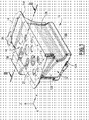
- la Fig.1 est une vue en perspective d'un carter d'huile selon l'invention ; et
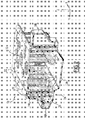
- la Fig.2 est une vue en coupe transversale en perspective du carter d'huile.
- La figure 1 représente un carter d'huile, désigné par la référence générale 10.
- Le carter d'huile 10 comprend une cuve 12, et, solidaire de cette dernière, une bride 14 de montage sur un carter de vilebrequin (non représenté) d'un moteur à combustion.
- La cuve 12 est constituée d'un fond 12A, en vis-à-vis de la bride 14, et de parois latérales 12B reliant le fond 12A à la bride 14.
- La cuve 12 délimite, d'une part, un volume de réception d'huile destinée à la lubrification du moteur à combustion, et, d'autre part, une ouverture supérieure 16 de passage de l'huile, bordée par la bride 14.
- L'huile au repos s'étend sur le fond 12A et s'élève le long des parois 12B jusqu'à un certain niveau, définissant un plan normalement horizontal X-Y.
- La bride 14 s'étend elle aussi dans un plan parallèle au niveau d'huile au repos, c'est-à-dire parallèlement au plan X-Y.
- La cuve 12 comporte deux excroissances 18A et 18B latérales par rapport à la bride 14, recouvrant en partie une face 14A inférieure, c'est-à-dire en vis-à-vis du fond 12B, de la bride 14. Ces excroissances 18A, 18B sont telles que le volume de réception d'huile fait saillie latéralement par rapport au cylindre de direction verticale Z, d'axe perpendiculaire au plan horizontal X-Y, s'appuyant sur un contour extérieur de la bride 14.
- Les excroissances 18A, 18B s'étendent chacune sur l'ensemble de la hauteur de la cuve 12, depuis le fond 12A jusqu'à la bride 14. Plus précisément, la première excroissance 18A est évasée depuis la bride 14 vers le fond 12A, et est formée essentiellement au voisinage du fond 12A. Quant à la seconde excroissance 18B, elle est évasée depuis le fond 12A vers la bride 14, et est formée essentiellement au voisinage de la bride 14. La forme des excroissances 18A, 18B est adaptée pour permettre l'intégration du carter d'huile 10 dans le moteur, avec les organes environnants.
- La bride 14 comprend des moyens 20 de fixation sur la bride du carter de vilebrequin. Dans l'exemple décrit, ces moyens de fixation 20 sont constitués de trous circulaires 20, ménagés dans la bride 14 et destinés à s'aligner en position montée du carter d'huile 10 avec des trous circulaires complémentaires ménagés dans la bride du carter de vilebrequin. Le carter d'huile 10 peut ainsi être fixé au moyen de vis dont la tête s'appuie sur la bride 14 à la périphérie des trous 20.
- Par ailleurs, le carter d'huile 10 comporte une plaque anti-émulsion 22, partiellement évidée et recouvrant l'ouverture supérieure 16 de la cuve 12.
- En référence à la figure 2, pour chacun des trous 20 recouverts par les excroissances 18A, 18B, le carter 10 comporte un canon 24 de forme cylindrique à section circulaire.
- Les canons 24 sont ménagés verticalement dans la cuve 12, de part en part dans le sens de la hauteur. Ils s'étendent ainsi chacun depuis le fond 12A de la cuve 12, jusqu'à un trou 20 de la bride 14.
- Chaque canon 24 délimite un espace 26 d'insertion de vis communiquant avec l'extérieur de la cuve 12, d'un côté par le trou 20 de réception de vis, et de l'autre côté par une ouverture 28, ménagée dans la cuve et ayant une section supérieure à celle du trou 20.
- Le diamètre d'un canon 24 permet le passage d'une tête de vis, tandis que le diamètre d'un trou 20 ne permet que le passage du corps de la vis. Ainsi, lorsque la vis est insérée dans le trou 20, sa tête s'appuie sur une plage annulaire de largeur non nulle délimitée sur la face inférieure 14A de la bride 14, dans le canon 24.
- Dans l'exemple illustré, les canons d'insertion 24 sont venus de matière avec la cuve 12.
- Dans un mode de réalisation non représenté, le carter 10 comporte, pour chaque trou de fixation 20 recouvert par une saillie 18A, 18B de la cuve 12, une vis fixée à demeure au carter 10, dans l'espace 26 délimité par un canon 24, de manière à permettre son vissage dans le trou de fixation 20.
- Dans le mode de réalisation illustré, le carter 10 comprend en outre une crépine 30, venue de matière avec la cuve 12 et destinée à canaliser et filtrer l'huile aspirée par la pompe à huile.
- De préférence, l'ensemble de la cuve 12, de la bride 14, des canons 24, de la crépine 30 et de la plaque anti-émulsion 22 est constitué de matière plastique et réalisé en une seule opération de moulage.
- Au vu de ce qui précède, il apparaît clairement qu'un carter d'huile selon l'invention permet d'augmenter le volume de réception d'huile : dans l'exemple décrit précédemment, ce volume est de l'ordre de 6 litres.
Claims (10)
- Carter d'huile comportant une cuve (12) délimitant, d'une part, un volume de réception d'huile, et, d'autre part, une ouverture supérieure (16) bordée par une bride (14) solidaire de la cuve (22) pour le montage sur un organe complémentaire d'un moteur à combustion d'un véhicule automobile, la cuve (12) présentant une excroissance (18A, 18B) telle que le volume de réception d'huile fait saillie latéralement par rapport au cylindre de direction (Z) d'axe perpendiculaire au niveau d'huile au repos dans le carter et s'appuyant sur un contour extérieur de la bride (14), la bride (14) comportant un trou (20) de réception d'une vis caractérisé en ce que le trou (20) est bordé par une surface annulaire d'appui pour une tête de vis et en ce qu'un canon (24) d'insertion de la vis, traversant la cuve (12) est ménagé dans la cuve (12) pour la fixation sur l'organe complémentaire dans la zone couverte par l'excroissance (18A, 18B).
- Carter d'huile selon la revendication 1, caractérisé en ce que la bride (14) définit un plan parallèle au niveau d'huile au repos dans le carter.
- Carter d'huile selon la revendication 1 ou 2, caractérisé en ce qu'il comporte une vis, insérée dans le canon (24) et fixée à demeure de manière à permettre son vissage.
- Carter d'huile selon l'une quelconque des revendications 1 à 3, caractérisé en ce que le canon est de forme cylindrique et délimite un espace (26) d'insertion de vis communiquant avec l'extérieur de la cuve (12), d'un côté par le trou (20) de réception de vis, et de l'autre côté par une ouverture (28) ménagée dans la cuve (12) ayant une section supérieure à celle du trou (20) de réception de vis.
- Carter d'huile selon l'une quelconque des revendications 1 à 4, caractérisé en ce qu'il comporte plusieurs canons (24) tous d'axes parallèles et s'étendant perpendiculairement au niveau d'huile au repos dans le carter.
- Carter d'huile selon l'une quelconque des revendications précédentes, caractérisé en ce qu'il est constitué de matière plastique.
- Carter d'huile selon l'une quelconque des revendications précédentes, caractérisé en ce que le ou les canons (24) sont venus de matière avec la cuve (12).
- Carter d'huile selon l'une quelconque des revendications précédentes, caractérisé en ce qu'il comporte une crépine (30) venue de matière avec la cuve (12).
- Carter d'huile selon l'une quelconque des revendications précédentes, caractérisé en ce qu'il comporte une plaque anti-émulsion (22) venue de matière avec la cuve (12).
- Moteur à combustion d'un véhicule automobile, caractérisé en ce qu'il comporte un carter d'huile selon l'une quelconque des revendications 1 à 9.
Applications Claiming Priority (1)
| Application Number | Priority Date | Filing Date | Title |
|---|---|---|---|
| FR0504017A FR2884873B1 (fr) | 2005-04-21 | 2005-04-21 | Carter d'huile et moteur a combustion |
Publications (2)
| Publication Number | Publication Date |
|---|---|
| EP1715145A1 true EP1715145A1 (fr) | 2006-10-25 |
| EP1715145B1 EP1715145B1 (fr) | 2010-07-28 |
Family
ID=35207603
Family Applications (1)
| Application Number | Title | Priority Date | Filing Date |
|---|---|---|---|
| EP06300373A Expired - Lifetime EP1715145B1 (fr) | 2005-04-21 | 2006-04-19 | Carter d'huile et moteur a combustion |
Country Status (5)
| Country | Link |
|---|---|
| EP (1) | EP1715145B1 (fr) |
| AT (1) | ATE475786T1 (fr) |
| DE (1) | DE602006015734D1 (fr) |
| ES (1) | ES2347171T3 (fr) |
| FR (1) | FR2884873B1 (fr) |
Cited By (3)
| Publication number | Priority date | Publication date | Assignee | Title |
|---|---|---|---|---|
| EP2025889A1 (fr) * | 2007-08-14 | 2009-02-18 | Basf Se | Carter d'huile pour moteur à combustion interne |
| WO2009077133A1 (fr) * | 2007-12-14 | 2009-06-25 | Elringklinger Ag | Cuvette collectrice d'huile |
| FR3027997A1 (fr) * | 2014-11-05 | 2016-05-06 | Peugeot Citroen Automobiles Sa | Carter d’huile avec boitier de liaison contenant de l’huile |
Citations (8)
| Publication number | Priority date | Publication date | Assignee | Title |
|---|---|---|---|---|
| JPS62247158A (ja) * | 1986-04-18 | 1987-10-28 | Mazda Motor Corp | エンジンのオイルパン構造 |
| JPH03199608A (ja) * | 1989-12-26 | 1991-08-30 | Kubota Corp | エンジンのオイル貯溜装置 |
| US5130014A (en) | 1989-11-30 | 1992-07-14 | General Motors Corporation | Removable sump oil pan for an internal combustion engine |
| US5662080A (en) * | 1994-11-12 | 1997-09-02 | Yamaha Hatsudoki Kabushiki Kaisha | Engine crankcase |
| JP3199608B2 (ja) | 1995-07-04 | 2001-08-20 | 出戸水栓株式会社 | 蛇口用切換コック |
| US20010037788A1 (en) | 1999-08-04 | 2001-11-08 | Pacific Industrial Co., Ltd. | Engine oil pan and forming method and apparatus |
| US6705270B1 (en) * | 2000-04-26 | 2004-03-16 | Basf Corporation | Oil pan module for internal combustion engines |
| EP1526258A1 (fr) * | 2003-10-21 | 2005-04-27 | Autotech Engineering, A.I.E. | Carter d'huile pour un moteur ayant capacité augmentée |
Family Cites Families (3)
| Publication number | Priority date | Publication date | Assignee | Title |
|---|---|---|---|---|
| FR1021184A (fr) * | 1949-06-30 | 1953-02-16 | Fiat Spa | Carteur pour moteurs à combustion interne de véhicules automobiles |
| DE2751982C2 (de) * | 1977-11-22 | 1982-11-18 | Daimler-Benz Ag, 7000 Stuttgart | Ölwanne für eine Mehrzylinder-Brennkraftmaschine |
| DE4334858C1 (de) * | 1993-10-13 | 1995-04-20 | Vaw Ver Aluminium Werke Ag | Ölwanne und Verfahren zu ihrer Herstellung |
-
2005
- 2005-04-21 FR FR0504017A patent/FR2884873B1/fr not_active Expired - Fee Related
-
2006
- 2006-04-19 EP EP06300373A patent/EP1715145B1/fr not_active Expired - Lifetime
- 2006-04-19 AT AT06300373T patent/ATE475786T1/de not_active IP Right Cessation
- 2006-04-19 DE DE602006015734T patent/DE602006015734D1/de not_active Expired - Lifetime
- 2006-04-19 ES ES06300373T patent/ES2347171T3/es not_active Expired - Lifetime
Patent Citations (8)
| Publication number | Priority date | Publication date | Assignee | Title |
|---|---|---|---|---|
| JPS62247158A (ja) * | 1986-04-18 | 1987-10-28 | Mazda Motor Corp | エンジンのオイルパン構造 |
| US5130014A (en) | 1989-11-30 | 1992-07-14 | General Motors Corporation | Removable sump oil pan for an internal combustion engine |
| JPH03199608A (ja) * | 1989-12-26 | 1991-08-30 | Kubota Corp | エンジンのオイル貯溜装置 |
| US5662080A (en) * | 1994-11-12 | 1997-09-02 | Yamaha Hatsudoki Kabushiki Kaisha | Engine crankcase |
| JP3199608B2 (ja) | 1995-07-04 | 2001-08-20 | 出戸水栓株式会社 | 蛇口用切換コック |
| US20010037788A1 (en) | 1999-08-04 | 2001-11-08 | Pacific Industrial Co., Ltd. | Engine oil pan and forming method and apparatus |
| US6705270B1 (en) * | 2000-04-26 | 2004-03-16 | Basf Corporation | Oil pan module for internal combustion engines |
| EP1526258A1 (fr) * | 2003-10-21 | 2005-04-27 | Autotech Engineering, A.I.E. | Carter d'huile pour un moteur ayant capacité augmentée |
Non-Patent Citations (2)
| Title |
|---|
| PATENT ABSTRACTS OF JAPAN vol. 012, no. 120 (M - 685) 14 April 1988 (1988-04-14) * |
| PATENT ABSTRACTS OF JAPAN vol. 015, no. 463 (M - 1183) 25 November 1991 (1991-11-25) * |
Cited By (3)
| Publication number | Priority date | Publication date | Assignee | Title |
|---|---|---|---|---|
| EP2025889A1 (fr) * | 2007-08-14 | 2009-02-18 | Basf Se | Carter d'huile pour moteur à combustion interne |
| WO2009077133A1 (fr) * | 2007-12-14 | 2009-06-25 | Elringklinger Ag | Cuvette collectrice d'huile |
| FR3027997A1 (fr) * | 2014-11-05 | 2016-05-06 | Peugeot Citroen Automobiles Sa | Carter d’huile avec boitier de liaison contenant de l’huile |
Also Published As
| Publication number | Publication date |
|---|---|
| FR2884873B1 (fr) | 2011-02-11 |
| DE602006015734D1 (de) | 2010-09-09 |
| ATE475786T1 (de) | 2010-08-15 |
| EP1715145B1 (fr) | 2010-07-28 |
| FR2884873A1 (fr) | 2006-10-27 |
| ES2347171T3 (es) | 2010-10-26 |
Similar Documents
| Publication | Publication Date | Title |
|---|---|---|
| EP1283376B1 (fr) | Support antivibratoire hydraulique | |
| FR2806771A1 (fr) | Ressort pneumatique comportant un amortisseur d'oscillations variable en fonction de la pression de support | |
| FR2787850A1 (fr) | Dispositif d'isolation antivibratoire rempli de liquide | |
| FR2900687A1 (fr) | Carter d'huile pour moteur a combustion interne | |
| EP1715145B1 (fr) | Carter d'huile et moteur a combustion | |
| EP1026420B1 (fr) | Support antivibratoire et son procédé de fabrication | |
| FR2958228A1 (fr) | Dispositif de montage d'un boitier de pedale d'accelerateur sur un support dans un vehicule automobile | |
| EP1348876A1 (fr) | Dispositif de fixation et de découplage vibratoire bimatière | |
| FR2488842A1 (fr) | Capuchon pour la tete de fixation du bras d'entrainement d'un balai d'essuie-glace | |
| FR2950591A1 (fr) | Dispositif d'installation d'un reservoir de fluide pour vehicule, notamment pour un vehicule automobile. | |
| FR2932728A1 (fr) | Cloison anti-recyclage d'air pour vehicule | |
| FR2863025A1 (fr) | Dispositif d'accouplement de deux arbres en rotation | |
| FR3025471B1 (fr) | Dispositif de support de moteur d'essuie-glace | |
| FR3102827A1 (fr) | Dispositif de correction d’assiette pour projecteur de véhicule automobile | |
| EP3205537B1 (fr) | Adaptateur constitutif d'un système d'essuyage | |
| FR2897115A1 (fr) | Dispositif de maintien d'une pompe electrique dans un reservoir de carburant | |
| EP3953214A1 (fr) | Dispositif de vide-poche de garnissage de portiere de vehicule | |
| FR3037736A1 (fr) | Ensemble pour demarreur | |
| FR2784598A1 (fr) | Filtre a liquide pour moteur a combustion interne | |
| FR3043617A1 (fr) | Capuchon equipant un connecteur pour un balai d’essuyage d’un vehicule automobile. | |
| FR3132480A1 (fr) | Dispositif de support de dispositif mobile pour une paroi de coffre de véhicule | |
| FR3080900A1 (fr) | Boite de vitesse etanche et procede d’assemblage d’une telle boite de vitesse | |
| FR3163019A1 (fr) | Dispositif de butée de suspension | |
| FR3080647A1 (fr) | Ensemble de linguet comportant un moyen de detrompage. | |
| FR2877072A1 (fr) | Trappe d'acces d'un couvercle carter de distribution |
Legal Events
| Date | Code | Title | Description |
|---|---|---|---|
| PUAI | Public reference made under article 153(3) epc to a published international application that has entered the european phase |
Free format text: ORIGINAL CODE: 0009012 |
|
| AK | Designated contracting states |
Kind code of ref document: A1 Designated state(s): AT BE BG CH CY CZ DE DK EE ES FI FR GB GR HU IE IS IT LI LT LU LV MC NL PL PT RO SE SI SK TR |
|
| AX | Request for extension of the european patent |
Extension state: AL BA HR MK YU |
|
| 17P | Request for examination filed |
Effective date: 20070323 |
|
| 17Q | First examination report despatched |
Effective date: 20070419 |
|
| AKX | Designation fees paid |
Designated state(s): AT BE BG CH CY CZ DE DK EE ES FI FR GB GR HU IE IS IT LI LT LU LV MC NL PL PT RO SE SI SK TR |
|
| APBN | Date of receipt of notice of appeal recorded |
Free format text: ORIGINAL CODE: EPIDOSNNOA2E |
|
| APBR | Date of receipt of statement of grounds of appeal recorded |
Free format text: ORIGINAL CODE: EPIDOSNNOA3E |
|
| APAF | Appeal reference modified |
Free format text: ORIGINAL CODE: EPIDOSCREFNE |
|
| APBT | Appeal procedure closed |
Free format text: ORIGINAL CODE: EPIDOSNNOA9E |
|
| GRAP | Despatch of communication of intention to grant a patent |
Free format text: ORIGINAL CODE: EPIDOSNIGR1 |
|
| GRAS | Grant fee paid |
Free format text: ORIGINAL CODE: EPIDOSNIGR3 |
|
| GRAA | (expected) grant |
Free format text: ORIGINAL CODE: 0009210 |
|
| AK | Designated contracting states |
Kind code of ref document: B1 Designated state(s): AT BE BG CH CY CZ DE DK EE ES FI FR GB GR HU IE IS IT LI LT LU LV MC NL PL PT RO SE SI SK TR |
|
| REG | Reference to a national code |
Ref country code: GB Ref legal event code: FG4D Free format text: NOT ENGLISH |
|
| REG | Reference to a national code |
Ref country code: CH Ref legal event code: EP |
|
| REG | Reference to a national code |
Ref country code: IE Ref legal event code: FG4D Free format text: LANGUAGE OF EP DOCUMENT: FRENCH |
|
| REF | Corresponds to: |
Ref document number: 602006015734 Country of ref document: DE Date of ref document: 20100909 Kind code of ref document: P |
|
| REG | Reference to a national code |
Ref country code: ES Ref legal event code: FG2A Ref document number: 2347171 Country of ref document: ES Kind code of ref document: T3 |
|
| REG | Reference to a national code |
Ref country code: GB Ref legal event code: 746 Effective date: 20101006 |
|
| REG | Reference to a national code |
Ref country code: NL Ref legal event code: VDEP Effective date: 20100728 |
|
| LTIE | Lt: invalidation of european patent or patent extension |
Effective date: 20100728 |
|
| PG25 | Lapsed in a contracting state [announced via postgrant information from national office to epo] |
Ref country code: NL Free format text: LAPSE BECAUSE OF FAILURE TO SUBMIT A TRANSLATION OF THE DESCRIPTION OR TO PAY THE FEE WITHIN THE PRESCRIBED TIME-LIMIT Effective date: 20100728 Ref country code: AT Free format text: LAPSE BECAUSE OF FAILURE TO SUBMIT A TRANSLATION OF THE DESCRIPTION OR TO PAY THE FEE WITHIN THE PRESCRIBED TIME-LIMIT Effective date: 20100728 Ref country code: FI Free format text: LAPSE BECAUSE OF FAILURE TO SUBMIT A TRANSLATION OF THE DESCRIPTION OR TO PAY THE FEE WITHIN THE PRESCRIBED TIME-LIMIT Effective date: 20100728 Ref country code: LT Free format text: LAPSE BECAUSE OF FAILURE TO SUBMIT A TRANSLATION OF THE DESCRIPTION OR TO PAY THE FEE WITHIN THE PRESCRIBED TIME-LIMIT Effective date: 20100728 |
|
| REG | Reference to a national code |
Ref country code: ES Ref legal event code: GC2A Effective date: 20110207 |
|
| REG | Reference to a national code |
Ref country code: ES Ref legal event code: GC2A Effective date: 20110214 |
|
| PG25 | Lapsed in a contracting state [announced via postgrant information from national office to epo] |
Ref country code: PT Free format text: LAPSE BECAUSE OF FAILURE TO SUBMIT A TRANSLATION OF THE DESCRIPTION OR TO PAY THE FEE WITHIN THE PRESCRIBED TIME-LIMIT Effective date: 20101129 Ref country code: PL Free format text: LAPSE BECAUSE OF FAILURE TO SUBMIT A TRANSLATION OF THE DESCRIPTION OR TO PAY THE FEE WITHIN THE PRESCRIBED TIME-LIMIT Effective date: 20100728 Ref country code: BG Free format text: LAPSE BECAUSE OF FAILURE TO SUBMIT A TRANSLATION OF THE DESCRIPTION OR TO PAY THE FEE WITHIN THE PRESCRIBED TIME-LIMIT Effective date: 20101028 Ref country code: CY Free format text: LAPSE BECAUSE OF FAILURE TO SUBMIT A TRANSLATION OF THE DESCRIPTION OR TO PAY THE FEE WITHIN THE PRESCRIBED TIME-LIMIT Effective date: 20100728 Ref country code: IS Free format text: LAPSE BECAUSE OF FAILURE TO SUBMIT A TRANSLATION OF THE DESCRIPTION OR TO PAY THE FEE WITHIN THE PRESCRIBED TIME-LIMIT Effective date: 20101128 Ref country code: SI Free format text: LAPSE BECAUSE OF FAILURE TO SUBMIT A TRANSLATION OF THE DESCRIPTION OR TO PAY THE FEE WITHIN THE PRESCRIBED TIME-LIMIT Effective date: 20100728 |
|
| REG | Reference to a national code |
Ref country code: IE Ref legal event code: FD4D |
|
| PG25 | Lapsed in a contracting state [announced via postgrant information from national office to epo] |
Ref country code: GR Free format text: LAPSE BECAUSE OF FAILURE TO SUBMIT A TRANSLATION OF THE DESCRIPTION OR TO PAY THE FEE WITHIN THE PRESCRIBED TIME-LIMIT Effective date: 20101029 Ref country code: LV Free format text: LAPSE BECAUSE OF FAILURE TO SUBMIT A TRANSLATION OF THE DESCRIPTION OR TO PAY THE FEE WITHIN THE PRESCRIBED TIME-LIMIT Effective date: 20100728 Ref country code: SE Free format text: LAPSE BECAUSE OF FAILURE TO SUBMIT A TRANSLATION OF THE DESCRIPTION OR TO PAY THE FEE WITHIN THE PRESCRIBED TIME-LIMIT Effective date: 20100728 |
|
| PG25 | Lapsed in a contracting state [announced via postgrant information from national office to epo] |
Ref country code: DK Free format text: LAPSE BECAUSE OF FAILURE TO SUBMIT A TRANSLATION OF THE DESCRIPTION OR TO PAY THE FEE WITHIN THE PRESCRIBED TIME-LIMIT Effective date: 20100728 Ref country code: IE Free format text: LAPSE BECAUSE OF FAILURE TO SUBMIT A TRANSLATION OF THE DESCRIPTION OR TO PAY THE FEE WITHIN THE PRESCRIBED TIME-LIMIT Effective date: 20100728 |
|
| PG25 | Lapsed in a contracting state [announced via postgrant information from national office to epo] |
Ref country code: RO Free format text: LAPSE BECAUSE OF FAILURE TO SUBMIT A TRANSLATION OF THE DESCRIPTION OR TO PAY THE FEE WITHIN THE PRESCRIBED TIME-LIMIT Effective date: 20100728 Ref country code: CZ Free format text: LAPSE BECAUSE OF FAILURE TO SUBMIT A TRANSLATION OF THE DESCRIPTION OR TO PAY THE FEE WITHIN THE PRESCRIBED TIME-LIMIT Effective date: 20100728 Ref country code: EE Free format text: LAPSE BECAUSE OF FAILURE TO SUBMIT A TRANSLATION OF THE DESCRIPTION OR TO PAY THE FEE WITHIN THE PRESCRIBED TIME-LIMIT Effective date: 20100728 Ref country code: SK Free format text: LAPSE BECAUSE OF FAILURE TO SUBMIT A TRANSLATION OF THE DESCRIPTION OR TO PAY THE FEE WITHIN THE PRESCRIBED TIME-LIMIT Effective date: 20100728 |
|
| PLBE | No opposition filed within time limit |
Free format text: ORIGINAL CODE: 0009261 |
|
| STAA | Information on the status of an ep patent application or granted ep patent |
Free format text: STATUS: NO OPPOSITION FILED WITHIN TIME LIMIT |
|
| 26N | No opposition filed |
Effective date: 20110429 |
|
| REG | Reference to a national code |
Ref country code: DE Ref legal event code: R097 Ref document number: 602006015734 Country of ref document: DE Effective date: 20110429 |
|
| BERE | Be: lapsed |
Owner name: PEUGEOT CITROEN AUTOMOBILES SA Effective date: 20110430 |
|
| PG25 | Lapsed in a contracting state [announced via postgrant information from national office to epo] |
Ref country code: MC Free format text: LAPSE BECAUSE OF NON-PAYMENT OF DUE FEES Effective date: 20110430 |
|
| REG | Reference to a national code |
Ref country code: CH Ref legal event code: PL |
|
| PG25 | Lapsed in a contracting state [announced via postgrant information from national office to epo] |
Ref country code: LI Free format text: LAPSE BECAUSE OF NON-PAYMENT OF DUE FEES Effective date: 20110430 Ref country code: BE Free format text: LAPSE BECAUSE OF NON-PAYMENT OF DUE FEES Effective date: 20110430 Ref country code: CH Free format text: LAPSE BECAUSE OF NON-PAYMENT OF DUE FEES Effective date: 20110430 |
|
| PGFP | Annual fee paid to national office [announced via postgrant information from national office to epo] |
Ref country code: IT Payment date: 20120321 Year of fee payment: 7 Ref country code: GB Payment date: 20120328 Year of fee payment: 7 |
|
| PGFP | Annual fee paid to national office [announced via postgrant information from national office to epo] |
Ref country code: ES Payment date: 20120323 Year of fee payment: 7 |
|
| PG25 | Lapsed in a contracting state [announced via postgrant information from national office to epo] |
Ref country code: LU Free format text: LAPSE BECAUSE OF NON-PAYMENT OF DUE FEES Effective date: 20110419 |
|
| PG25 | Lapsed in a contracting state [announced via postgrant information from national office to epo] |
Ref country code: TR Free format text: LAPSE BECAUSE OF FAILURE TO SUBMIT A TRANSLATION OF THE DESCRIPTION OR TO PAY THE FEE WITHIN THE PRESCRIBED TIME-LIMIT Effective date: 20100728 |
|
| PG25 | Lapsed in a contracting state [announced via postgrant information from national office to epo] |
Ref country code: HU Free format text: LAPSE BECAUSE OF FAILURE TO SUBMIT A TRANSLATION OF THE DESCRIPTION OR TO PAY THE FEE WITHIN THE PRESCRIBED TIME-LIMIT Effective date: 20100728 |
|
| GBPC | Gb: european patent ceased through non-payment of renewal fee |
Effective date: 20130419 |
|
| PG25 | Lapsed in a contracting state [announced via postgrant information from national office to epo] |
Ref country code: GB Free format text: LAPSE BECAUSE OF NON-PAYMENT OF DUE FEES Effective date: 20130419 |
|
| PG25 | Lapsed in a contracting state [announced via postgrant information from national office to epo] |
Ref country code: IT Free format text: LAPSE BECAUSE OF NON-PAYMENT OF DUE FEES Effective date: 20130419 |
|
| REG | Reference to a national code |
Ref country code: ES Ref legal event code: FD2A Effective date: 20140609 |
|
| PG25 | Lapsed in a contracting state [announced via postgrant information from national office to epo] |
Ref country code: ES Free format text: LAPSE BECAUSE OF NON-PAYMENT OF DUE FEES Effective date: 20130420 |
|
| REG | Reference to a national code |
Ref country code: FR Ref legal event code: PLFP Year of fee payment: 11 |
|
| PGFP | Annual fee paid to national office [announced via postgrant information from national office to epo] |
Ref country code: FR Payment date: 20160323 Year of fee payment: 11 |
|
| PGFP | Annual fee paid to national office [announced via postgrant information from national office to epo] |
Ref country code: DE Payment date: 20160321 Year of fee payment: 11 |
|
| REG | Reference to a national code |
Ref country code: DE Ref legal event code: R119 Ref document number: 602006015734 Country of ref document: DE |
|
| REG | Reference to a national code |
Ref country code: FR Ref legal event code: ST Effective date: 20171229 |
|
| PG25 | Lapsed in a contracting state [announced via postgrant information from national office to epo] |
Ref country code: DE Free format text: LAPSE BECAUSE OF NON-PAYMENT OF DUE FEES Effective date: 20171103 Ref country code: FR Free format text: LAPSE BECAUSE OF NON-PAYMENT OF DUE FEES Effective date: 20170502 |