EP1714799A2 - Rolle mit einer Bremseinrichtung - Google Patents
Rolle mit einer Bremseinrichtung Download PDFInfo
- Publication number
- EP1714799A2 EP1714799A2 EP06005353A EP06005353A EP1714799A2 EP 1714799 A2 EP1714799 A2 EP 1714799A2 EP 06005353 A EP06005353 A EP 06005353A EP 06005353 A EP06005353 A EP 06005353A EP 1714799 A2 EP1714799 A2 EP 1714799A2
- Authority
- EP
- European Patent Office
- Prior art keywords
- lever
- roller according
- rocker arm
- arm
- cam
- Prior art date
- Legal status (The legal status is an assumption and is not a legal conclusion. Google has not performed a legal analysis and makes no representation as to the accuracy of the status listed.)
- Granted
Links
Images
Classifications
-
- B—PERFORMING OPERATIONS; TRANSPORTING
- B60—VEHICLES IN GENERAL
- B60B—VEHICLE WHEELS; CASTORS; AXLES FOR WHEELS OR CASTORS; INCREASING WHEEL ADHESION
- B60B33/00—Castors in general; Anti-clogging castors
- B60B33/0002—Castors in general; Anti-clogging castors assembling to the object, e.g. furniture
- B60B33/0015—Castors in general; Anti-clogging castors assembling to the object, e.g. furniture characterised by adaptations made to castor
- B60B33/0018—Castors in general; Anti-clogging castors assembling to the object, e.g. furniture characterised by adaptations made to castor in the form of a flat mounting plate
-
- B—PERFORMING OPERATIONS; TRANSPORTING
- B60—VEHICLES IN GENERAL
- B60B—VEHICLE WHEELS; CASTORS; AXLES FOR WHEELS OR CASTORS; INCREASING WHEEL ADHESION
- B60B33/00—Castors in general; Anti-clogging castors
- B60B33/0078—Castors in general; Anti-clogging castors characterised by details of the wheel braking mechanism
- B60B33/0081—Castors in general; Anti-clogging castors characterised by details of the wheel braking mechanism acting on tyre tread
-
- B—PERFORMING OPERATIONS; TRANSPORTING
- B60—VEHICLES IN GENERAL
- B60B—VEHICLE WHEELS; CASTORS; AXLES FOR WHEELS OR CASTORS; INCREASING WHEEL ADHESION
- B60B33/00—Castors in general; Anti-clogging castors
- B60B33/0078—Castors in general; Anti-clogging castors characterised by details of the wheel braking mechanism
- B60B33/0092—Castors in general; Anti-clogging castors characterised by details of the wheel braking mechanism actuated remotely, e.g. by cable or electrically
-
- B—PERFORMING OPERATIONS; TRANSPORTING
- B60—VEHICLES IN GENERAL
- B60B—VEHICLE WHEELS; CASTORS; AXLES FOR WHEELS OR CASTORS; INCREASING WHEEL ADHESION
- B60B33/00—Castors in general; Anti-clogging castors
- B60B33/02—Castors in general; Anti-clogging castors with disengageable swivel action, i.e. comprising a swivel locking mechanism
- B60B33/021—Castors in general; Anti-clogging castors with disengageable swivel action, i.e. comprising a swivel locking mechanism combined with braking of castor wheel
-
- B—PERFORMING OPERATIONS; TRANSPORTING
- B60—VEHICLES IN GENERAL
- B60B—VEHICLE WHEELS; CASTORS; AXLES FOR WHEELS OR CASTORS; INCREASING WHEEL ADHESION
- B60B33/00—Castors in general; Anti-clogging castors
- B60B33/02—Castors in general; Anti-clogging castors with disengageable swivel action, i.e. comprising a swivel locking mechanism
- B60B33/025—Castors in general; Anti-clogging castors with disengageable swivel action, i.e. comprising a swivel locking mechanism by using form-fit, e.g. front teeth
-
- B—PERFORMING OPERATIONS; TRANSPORTING
- B60—VEHICLES IN GENERAL
- B60B—VEHICLE WHEELS; CASTORS; AXLES FOR WHEELS OR CASTORS; INCREASING WHEEL ADHESION
- B60B33/00—Castors in general; Anti-clogging castors
- B60B33/02—Castors in general; Anti-clogging castors with disengageable swivel action, i.e. comprising a swivel locking mechanism
- B60B33/026—Castors in general; Anti-clogging castors with disengageable swivel action, i.e. comprising a swivel locking mechanism being actuated remotely, e.g. by cable or electrically
Definitions
- the invention relates to a generic role with a braking device according to the preamble of the main claim, ie a roller with a braking device with a movable in its axial direction against the force of a spring and the bearing shells centrally traversing bolts at its rear end for the purpose of braking at least one actuator actuated and thereby forward in the axial direction is displaced so that it comes with a provided at its rear end opposite to the front end of the brake element on the circumference of a held in a U-shaped fork of the roll wheel for the purpose of braking the same comes to rest.
- Such roles are known per se ( DE-U 297 08 693 ). They are, for example, attached to the underside of containers, for example refuse containers, and have, for example, a controllable braking device for at least two groups of rollers via a central rod device.
- a cam of the brake device is pressed on the head of a bearing shells passing centrally through the bolt. This one points to his opposite end to a brake element which comes to rest on the circumference of the wheel, which is supported in a U-shaped fork of the roller.
- the bolt can be rotationally and only movably supported along its axial direction.
- the braking device may be designed as a so-called parking brake for the purpose of permanent locking or as a driving brake during the movement of the roller, ie during operation of the container in order to reduce its speed.
- a disadvantage of this known embodiment is the fact that the braking device is designed either only as a parking brake or only as a driving brake, which limits the use of the known role.
- the invention is therefore the object of the brake device of the generic role at the same time both form a parking brake and as a driving brake.
- This object is achieved in a generic role according to the preamble of the main claim according to the invention by its characterizing features, ie the fact that the braking device has a tiltable about an axis lever, that the actuating member acts on a lever arm of the lever, that this when tilting to the Axis actuates the rear end of the bolt and that a lever engaging on the other actuator is provided.
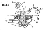
- a braking device has a generally designated 10 bottom plate for mounting, for example, on the bottom of containers such as dumpsters on.
- rotatable bearing shells 13 are provided for the formed in the embodiment shown as a steering roller role.
- a U-shaped fork 11 is fixed for receiving the wheel 12.
- the bearing shells 13 of the roller are held together by means of a centrally concentric receiving part, preferably a rivet.
- This and thus the bearing shells 13 are centrally traversed by a bolt 6 which is movable in its axial direction against the force of a spring 8, which pushes the bolt 6 in its unbraked position.
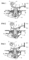
- the bolt 6 is actuated at its rear end for the purpose of braking by an actuator formed as a cam 1 and thereby forward in the axial direction so displaceable (Figure 2) that he vorgesehehen with a at its rear end opposite to the arranged front end brake element 9 on the circumference the wheel 12 supported in the U-shaped fork 11 of the roller comes to rest for the purpose of braking it.
- the cam is seated on an actuating shaft 7 and is rotated by, for example, the operation of a parking brake lever, e.g. swiveled clockwise with the foot.
- the braking device of the roller has one about an axis. 4 tiltable, provided between the cam 1 and the bolt 6 and designed as a two-armed rocker lever 3, on the one hand the axis 4 befindtsch a lever arm in the attacking cam 1 is provided with a sliding contour 2 and of the bolt 6 in his Neutral position (Figure 1) is pushed.
- the sliding contour 2 is formed with a trough for Studentstotriosblocktechnik of the cam 1 to form a parking brake ( Figure 2).
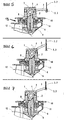
- the further actuating member may be formed with respect to the axis 4 of the other lever arm of the rocker arm 3 attacking further cam 5.1 ( Figure 4).
- the cam 1 and the further cam 5.1 based on the rocker arm 3 on its different sides, namely front or rear are arranged.
- the function corresponds to the first embodiment.
- the bolt 6 is at its rear end for the purpose of braking by a trained as a cam 1 actuator directly without the toggle lever 3 actuated.
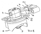
- the cam 1 is seated on the actuating shaft 7 and is rotated by, for example, the operation of a parking brake lever, e.g. pivoted with the foot via an actuating cam 14 ( Figure 8) in the counterclockwise direction.
- the braking device of the roller has a vorgeseheen on the operating shaft 7 storage 4, z.
- a sleeve provided as a rocker arm 3 lever formed the lever arm is pivoted from its neutral position ( Figure 5) to form a parking brake of the actuating shaft 7 via the bearing 4 ( Figure 6).
Landscapes
- Engineering & Computer Science (AREA)
- Mechanical Engineering (AREA)
- Braking Arrangements (AREA)
Abstract
Description
- Die Erfindung betrifft eine gattungsgemässe Rolle mit einer Bremseinrichtung nach dem Oberbegriff des Hauptanspruchs, also eine Rolle mit einer Bremseinrichtung mit einem in seiner Achsrichtung entgegen der Kraft einer Feder bewegbaren und die Lagerschalen mittig durchquerenden Bolzen, der an seinem rückwärtigen Ende zwecks Bremsung von zumindest einem Betätigungsglied betätigbar und dabei vorwärts in Achsrichtung so verschiebbar ist, dass er mit einem an seinem zu dem rückwärtigen Ende entgegengesetzt angeordneten vorderen Ende vorgesehehen Bremselement am Umfang eines in einer U-förmigen Gabel der Rolle gehalterten Rades zwecks Bremsung desselben zur Anlage kommt.
- Solche Rollen sind an sich bekannt (
DE-U 297 08 693 ). Sie werden beispielsweise an der Unterseite von Containern, beispielsweise Müllcontainern angebracht und weisen z.B. über eine zentrale Stangeneinrichtung steuerbare Bremsvorrichtung für zumindest zweier Gruppen von Rollen auf. Mittels eines Nockens der Bremsvorrichtung wird auf den Kopf eines die Lagerschalen mittig durchquerenden Bolzens gedrückt. Dieser weist an seinem entgegengesetzten Ende ein Bremselement auf, welches am Umfang des Rades zur Anlage kommt, das in einer U-förmigen Gabel der Rolle gehaltert ist. Hierbei kann der Bolzen verdrehfest und nur längs seiner Achsrichtung beweglich gehaltert. Dabei kann die Bremseinrichtung als sogenannte Feststellbremse zwecks dauerhafter Arretierung oder als Fahrbremse während der Bewegung der Rolle, also im Betrieb des Containers ausgebildet sein, um dessen Geschwindigkeit herabzusetzen. - Von Nachteil bei dieser bekannten Ausführungsform ist die Tatsache, dass die Bremseinrichtung entweder nur als Feststellbremse oder aber nur als Fahrbremse ausgebildet ist, was den Einsatz der bekannten Rolle einschränkt.
- Der Erfindung liegt deshalb die Aufgabe zugrunde, die Bremseinrichtung der gattungsgemässen Rolle zugleich sowohl als Feststellbremse als auch als Fahrbremse auszubilden.
- Diese Aufgabe wird erfindungsgemäß bei einer gattungsgemässen Rolle nach dem Oberbegriff des Hauptanspruchs erfindungsgemäss durch dessen kennzeichnende Merkmale, also dadurch gelöst, dass die Bremseinrichtung einen um eine Achse kippbaren Hebel aufweist, dass das Betätigungsglied an einem Hebelarm des Hebels angreift, dass dieser beim Kippen um die Achse das rückwärtige Ende des Bolzens betätigt und dass ein an dem Hebel angreifendes weiteres Betätigungsglied vorgesehen ist.
- Hierdurch bedingt ist es erfindungsgemäss möglich, mittels zweier verschiedener Bremshebel, z.B. mittels eines mit dem Fuss zu betätigenden Feststellbremshebels und mittels eines Fahrbremshebels, z. B. in Form eines Handbremshebels über den Hebel auf ein und denselben Bolzen der Bremseinrichtung einzuwirken. Eine solche Rolle nach Lehre der Erfindung ist universeller einsetzbar.
- In zweckmässiger Weiterbildung der Erfindung kann auch über eine Betätigungswelle auf den daran drehfest angebrachten Hebel auf ein und denselben Bolzen der Bremseinrichtung eingewirkt werden.
- Weitere zweckmäßige Ausgestaltungen und Weiterbildung der Erfindung sind in den Unteransprüchen gekennzeichnet.
- Ein Ausführungsbeispiel der Erfindung wird nachfolgend unter Bezugnahme auf die Zeichnung näher erläutert. In dieser zeigt:
- Figur 1:
- eine erste Ausfürungsform der erfindungsgemässen Rolle, ungebremst, im schematischen Querschnitt
- Figur 2:
- die Rolle gemäss Figur 1, mit betätigter Feststellbremse
- Figur 3:
- die Rolle gemäss Figur 1, mit betätigter Fahrbremse und
- Figur 4:
- eine zweite Ausfürungsform der Rolle, mit betätigter Fahrbremse, im schematischen Querschnitt.
- Figur 5:
- eine dritte Ausfürungsform der Rolle, ungebremst, im schematischen Querschnitt
- Figur 6:
- die Rolle gemäss Figur 5, mit betätigter Feststellbremse
- Figur 7:
- die Rolle gemäss Figur 5, mit betätigter Fahrbremse und
- Figur 8:
- die Rolle, in schematischer perspektivischer Darstellung.
- Die schematisch in Figur 1 angedeutet dargestellte Rolle mit einer Bremseinrichtung weist eine insgesamt mit 10 bezeichnete Bodenplatte zum Anbau beispielsweise an der Unterseite von Containern wie Müllcontainern auf. An der Bodenplatte 10 sind zueinander drehbare Lagerschalen 13 für die beim wiedergegebenen Ausführungsbeispiel als Lenkrolle ausgebildete Rolle vorgesehen. An einer davon ist eine U-förmig ausgebildete Gabel 11 zur Aufnahme des Rades 12 festgelegt.
- Die Lagerschalen 13 der Rolle sind mittels eines sie zentrisch durchgreifenden Aufnahmeteils, vorzugsweise einem Hohlniet zusammengehalten. Dieses und damit die Lagerschalen 13 sind mittig von einem Bolzen 6 durchquert, der in seiner Achsrichtung entgegen der Kraft einer Feder 8 bewegbar ist, welche den Bolzen 6 in seine ungebremste Lage schiebt. Der Bolzen 6 ist an seinem rückwärtigen Ende zwecks Bremsung von einem als Nocken 1 ausgebildeten Betätigungsglied betätigbar und dabei vorwärts in der Achsrichtung so verschiebbar (Figur 2), dass er mit einem an seinem zu dem rückwärtigen Ende entgegengesetzt angeordneten vorderen Ende vorgesehehen Bremselement 9 am Umfang des in der U-förmigen Gabel 11 der Rolle gehalterten Rades 12 zwecks Bremsung desselben zur Anlage kommt. Der Nocken sitzt auf einer Betätigungswelle 7 und wird durch deren Drehung, bspw. infolge der Betätigung eines Feststellbremshebels z.B. mit dem Fuss im Uhrzeigersinn verschwenkt.
- Die Bremseinrichtung der Rolle weist einen um eine Achse 4 kippbaren, zwischen dem Nocken 1 und dem Bolzen 6 vorgesehenen und als zweiarmiger Kipphebel 3 ausgebildeten Hebel auf, dessen einerseits der Achse 4 befindlicher einer Hebelarm im Bereich des an ihm angreifenden Nockens 1 mit einer Gleitkontur 2 versehen ist und der von dem Bolzen 6 in seine Neutrallage (Figur 1) geschoben ist. Die Gleitkontur 2 ist mit einer Mulde zur Übertotpunktblockierung des Nockens 1 unter Bildung einer Feststellbremse ausgebildet (Figur 2).
- Es ist ferner bei der ersten Ausführungsform ein weiteres als Seilzug 5.2 ausgebildetes Betätigungsglied vorgesehen, das an dem auf der anderen Seite der Achse 4 befindlichen anderen Hebelarm des Kipphebels 3 über eine Schraubenfeder 5.3 angreift, die in der ungebremsten Neutrallage des Kipphebels 3 gespannt und in der Übertotpunktblockierung des Nockens 1 bei betätigter Feststellbremse (Figur 2) entspannt ist. Wird diese gelöst und wird der -nicht dargestellte- Fahrbremshebel, z. B. in Form eines Handbremshebel betätigt, so wird der Kipphebel 3 bei gespannter Schraubenfeder 5.3, wie auch beim Betätigen der Feststellbremse nach Figur 2 um die Achse 4 im Gegenuhrzeigersinn in die in Figur 3 gezeigte Fahrbremslage verschwenkt.
- In alternativer -zweiter- Ausführungsform der Rolle kann das weitere Betätigungsglied an mit Bezug auf die Achse 4 dem anderen Hebelarm des Kipphebels 3 angreifender weiterer Nocken 5.1 ausgebildet sein (Figur 4). Zugleich sind der Nocken 1 und der weiterere Nocken 5.1, bezogen auf den Kipphebel 3 auf dessen verschiedenen Seiten, nämlich Vorder- oder Rückseite angeordnet. Die Funktion entspricht jedoch der ersten Ausführungsform.
- Die schematisch in Figur 5 dagestellte dritte Ausführungsform der Rolle mit einer Bremseinrichtung weist einen ähnlichen Aufbau wie die erste und die zweite Ausführungsform auf, wobei zur Straffung des Textes gleiche Teile mit demselben Bezugszeichen versehen sind.
- Der Bolzen 6 ist an seinem rückwärtigen Ende zwecks Bremsung von einem als Nocken 1 ausgebildeten Betätigungsglied direkt ohne den Kipphebel 3 betätigbar. Der Nocken 1 sitzt auf der Betätigungswelle 7 und wird durch deren Drehung, bspw. infolge der Betätigung eines Feststellbremshebels z.B. mit dem Fuss über einen Betätigungsnocken 14 (Figur 8) im Gegenuhrzeigersinn verschwenkt.
- Die Bremseinrichtung der Rolle weist einen an der Betätigungswelle 7 vorgesehehen Lagerung 4, z. B. einer Hülse vorgesehenen als Kipphebel 3 ausgebildeten Hebel auf, dessen Hebelarm von seiner Neutrallage (Figur 5) unter Bildung einer Feststellbremse von der Betätigungswelle 7 über die Lagerung 4 verschwenkt ist (Figur 6).
- Es ist ferner bei der Rolle das weitere als Seilzug 5.2 ausgebildete Betätigungsglied vorgesehen, das an dem Hebelarm des Kipphebels 3 über die Schraubenfeder 5.3 angreift.
Claims (15)
- Rolle mit einer Bremseinrichtung mit einem in seiner Achsrichtung entgegen der Kraft einer Feder (8) bewegbaren und die Lagerschalen (13) mittig durchquerenden Bolzen (6), der an seinem rückwärtigen Ende zwecks Bremsung von zumindest einem Betätigungsglied (1) betätigbar und dabei vorwärts in Achsrichtung so verschiebbar ist, dass er mit einem an seinem zu dem rückwärtigen Ende entgegengesetzt angeordneten vorderen Ende vorgesehehen Bremselement (9) am Umfang eines in einer U-förmigen Gabel (11) der Rolle gehalterten Rades (12) zwecks Bremsung desselben zur Anlage kommt, dadu rch gekennzeichnet, dass die Bremseinrichtung einen um eine Achse (4) kippbaren Hebel (3) aufweist, dass das Betätigungsglied (1) an einem Hebelarm des Hebels (3) angreift, dass dieser beim Kippen um die Achse (4) das rückwärtige Ende des Bolzens (6) betätigt und dass ein an dem Hebel (3) angreifendes weiteres Betätigungsglied (5.1, 5.2) vorgesehen ist.
- Rolle nach Anspruch 1, dadurch gekennzeichnet, dass der Hebel (3) als zweiarmiger Kipphebel ausgebildet ist.
- Rolle nach Anspruch 2, dadurch gekennzeichnet, dass das Betätigungsglied an dem einem Hebelarm des Kipphebels (3) und das weitere Betätigungsglied an dem auf der anderen Seite der Achse (4) befindlichen anderen Hebelarm des Kipphebels (3) angreift.
- Rolle nach einem der Ansprüche 1 bis 3, dadurch gekennzeichnet, dass das Betätigungsglied als an dem einem Hebelarm des Kipphebels (3) angreifender Nocken (1) ausgebildet ist.
- Rolle nach Anspruch 4, dadurch gekennzeichnet, dass der eine Hebelarm des Kipphebels (3) im Bereich des an ihm angreifenden Nockens (1) mit einer Gleitkontur ausgebildet ist.
- Rolle nach Anspruch 5, dadurch gekennzeichnet, dass dass die Gleitkontur des einen Hebelarms des Kipphebels (3) mit einer Mulde zur Übertotpunktblockierung des Nockens (1) unter Bildung einer Feststellbremse ausgebildet ist.
- Rolle nach einem der Ansprüche 1 bis 3, dadurch gekennzeichnet, dass das weitere Betätigungsglied als an dem anderen Hebelarm des Kipphebels (3) angreifender weiterer Nocken (5.1) ausgebildet ist.
- Rolle nach Anspruch 4, dadurch gekennzeichnet, dass zwischen dem Nocken (1) und dem Bolzen (6) der Kipphebel (3) vorgesehen ist.
- Rolle nach Anspruch 7 oder 8, dadurch gekennzeichnet, dass der Nocken (1) und der weiterere Nocken (5.1) bezogen auf den Kipphebel (3) auf verschiedenen Seiten angeordnet sind.
- Rolle nach einem der Ansprüche 1 bis 3, dadurch gekennzeichnet, dass das weitere Betätigungsglied als an dem anderen Hebelarm des Kipphebels (3) angreifender Seilzug (5.2) ausgebildet ist.
- Rolle nach Anspruch 10, dadurch gekennzeichnet, dass der Seilzug (5.2) an dem anderen Hebelarm des Kipphebels (3) über eine Schraubenfeder (5.3) angreift.
- Rolle nach Anspruch 9, dadurch gekennzeichnet, dass der eine Hebelarm des Kipphebels (3) im Bereich des an ihm angreifenden Nockens (1) mit einer Gleitkontur ausgebildet ist.
- Rolle nach Anspruch 1, dadurch gekennzeichnet, dass das Betätigungsglied (1) über eine Betätigungswelle (7) betätigbar ist, dass auf der Betätigungswelle (7) ein an dieser drehfest angebrachter kippbarer Hebel (3) vorgesehen ist und dass ein an dem Hebel (3) angreifendes weiteres Betätigungsglied (5.2) vorgesehen ist.
- Rolle nach Anspruch 13, dadurch gekennzeichnet, dass das weitere Betätigungsglied als an dem Kipphebel (3) angreifender Seilzug (5.2) ausgebildet ist.
- Rolle nach Anspruch 14, dadurch gekennzeichnet, dass der Seilzug (5.2) an dem Kipphebel (3) über eine Schraubenfeder (5.3) angreift.
Applications Claiming Priority (2)
| Application Number | Priority Date | Filing Date | Title |
|---|---|---|---|
| DE200520006433 DE202005006433U1 (de) | 2005-04-21 | 2005-04-21 | Rolle mit einer Bremsvorrichtung |
| DE200520006434 DE202005006434U1 (de) | 2005-04-21 | 2005-04-21 | Rolle mit einer Bremsvorrichtung |
Publications (3)
| Publication Number | Publication Date |
|---|---|
| EP1714799A2 true EP1714799A2 (de) | 2006-10-25 |
| EP1714799A3 EP1714799A3 (de) | 2007-03-07 |
| EP1714799B1 EP1714799B1 (de) | 2008-07-23 |
Family
ID=36698771
Family Applications (1)
| Application Number | Title | Priority Date | Filing Date |
|---|---|---|---|
| EP06005353A Expired - Lifetime EP1714799B1 (de) | 2005-04-21 | 2006-03-16 | Rolle mit einer Bremseinrichtung |
Country Status (3)
| Country | Link |
|---|---|
| EP (1) | EP1714799B1 (de) |
| AT (1) | ATE402028T1 (de) |
| DE (1) | DE502006001161D1 (de) |
Cited By (2)
| Publication number | Priority date | Publication date | Assignee | Title |
|---|---|---|---|---|
| DE202009017461U1 (de) | 2009-12-17 | 2011-04-28 | Steinco Paul Vom Stein Gmbh | Brems- und Verriegelungssensor und -aktor für Rollen |
| DE102013206823B4 (de) * | 2013-04-16 | 2020-02-13 | Siemens Healthcare Gmbh | Bremsvorrichtung für ein zum Bewegen einer medizinischen Untersuchungs- und/oder Behandlungseinrichtung auf einem Untergrund ausgebildetes Bewegungsmittel |
Citations (1)
| Publication number | Priority date | Publication date | Assignee | Title |
|---|---|---|---|---|
| DE29708693U1 (de) | 1997-05-15 | 1997-10-09 | Heinrich Blickle GmbH & Co. KG Räder- und Rollenfabrik, 72348 Rosenfeld | Rolle |
Family Cites Families (2)
| Publication number | Priority date | Publication date | Assignee | Title |
|---|---|---|---|---|
| GB695213A (en) * | 1950-10-20 | 1953-08-05 | Benford Ltd | Improvements in or relating to castors |
| DE3624089A1 (de) * | 1986-07-17 | 1988-01-21 | Schulte Soehne Gmbh Co A | Feststellvorrichtung fuer lenkrollen von insbesondere muellcontainern |
-
2006
- 2006-03-16 EP EP06005353A patent/EP1714799B1/de not_active Expired - Lifetime
- 2006-03-16 DE DE502006001161T patent/DE502006001161D1/de not_active Expired - Lifetime
- 2006-03-16 AT AT06005353T patent/ATE402028T1/de active
Patent Citations (1)
| Publication number | Priority date | Publication date | Assignee | Title |
|---|---|---|---|---|
| DE29708693U1 (de) | 1997-05-15 | 1997-10-09 | Heinrich Blickle GmbH & Co. KG Räder- und Rollenfabrik, 72348 Rosenfeld | Rolle |
Cited By (3)
| Publication number | Priority date | Publication date | Assignee | Title |
|---|---|---|---|---|
| DE202009017461U1 (de) | 2009-12-17 | 2011-04-28 | Steinco Paul Vom Stein Gmbh | Brems- und Verriegelungssensor und -aktor für Rollen |
| DE102009058919A1 (de) | 2009-12-17 | 2011-06-22 | STEINCO Paul vom Stein GmbH, 42929 | Brems- und Verriegelungssensor und -aktor für Rollen |
| DE102013206823B4 (de) * | 2013-04-16 | 2020-02-13 | Siemens Healthcare Gmbh | Bremsvorrichtung für ein zum Bewegen einer medizinischen Untersuchungs- und/oder Behandlungseinrichtung auf einem Untergrund ausgebildetes Bewegungsmittel |
Also Published As
| Publication number | Publication date |
|---|---|
| EP1714799B1 (de) | 2008-07-23 |
| EP1714799A3 (de) | 2007-03-07 |
| DE502006001161D1 (de) | 2008-09-04 |
| ATE402028T1 (de) | 2008-08-15 |
Similar Documents
| Publication | Publication Date | Title |
|---|---|---|
| DE2522436C3 (de) | Nabenbremsen-Baugruppe für einen Krankenfahrstuhl | |
| DE2553667C3 (de) | Elektrischer Fensterheber für Kraftfahrzeuge | |
| DE4032885A1 (de) | Scheibenbremse fuer fahrzeuge, insbesondere strassenfahrzeuge | |
| DE3521794A1 (de) | Laufrolle | |
| DE3241575C2 (de) | ||
| EP1714799B1 (de) | Rolle mit einer Bremseinrichtung | |
| DE1257603C2 (de) | Mechanische betaetigungsvorrichtung fuer scheibenbremsen, insbesondere fuer kraftfahrzeuge | |
| EP0080630B1 (de) | Zweirad-Felgenbremse | |
| DE2542122C3 (de) | Mechanische Hilfslöseeinrichtung für Federspeicher- oder Kombizylinder | |
| EP0992701B1 (de) | Trommelbremse für ein Kraftfahrzeug | |
| DE19643798A1 (de) | Klemmvorrichtung für eine verstellbare Lenksäule | |
| DE202005006433U1 (de) | Rolle mit einer Bremsvorrichtung | |
| DE19525722C2 (de) | Zuspannvorrichtung für eine Scheibenbremse | |
| DE69924101T2 (de) | Radfeststellvorrichtung | |
| DE202005006434U1 (de) | Rolle mit einer Bremsvorrichtung | |
| DE3131813C1 (de) | Betaetigungs- und Nachstellvorrichtung fuer eine Teilbelag-Scheibenbremse | |
| EP3476655B1 (de) | Trägereinheit für eine dachträgeranordnung eines kraftfahrzeugs | |
| DE10006009C2 (de) | Flurförderzeug in Vierradausführung | |
| DE9315573U1 (de) | Fahrgerät | |
| EP1826080A1 (de) | Betätigungsvorrichtung für eine Feststellbremse eines Kraftfahrzeuges | |
| DE3018022A1 (de) | Bremsvorrichtung fuer fahrzeuge | |
| DE29502418U1 (de) | Feststellbremse für mindestens ein Laufrad eines Fahrgerätes | |
| DE112006001595T5 (de) | Scheibenbremse | |
| DE4401084C1 (de) | Mechanische Stellvorrichtung, insbesondere zur Betätigung einer Feststellbremse eines Kraftfahrzeuges | |
| DE9419360U1 (de) | Rücktrittbremse für Fahrräder mit Kettenschaltung |
Legal Events
| Date | Code | Title | Description |
|---|---|---|---|
| PUAI | Public reference made under article 153(3) epc to a published international application that has entered the european phase |
Free format text: ORIGINAL CODE: 0009012 |
|
| AK | Designated contracting states |
Kind code of ref document: A2 Designated state(s): AT BE BG CH CY CZ DE DK EE ES FI FR GB GR HU IE IS IT LI LT LU LV MC NL PL PT RO SE SI SK TR |
|
| AX | Request for extension of the european patent |
Extension state: AL BA HR MK YU |
|
| PUAL | Search report despatched |
Free format text: ORIGINAL CODE: 0009013 |
|
| AK | Designated contracting states |
Kind code of ref document: A3 Designated state(s): AT BE BG CH CY CZ DE DK EE ES FI FR GB GR HU IE IS IT LI LT LU LV MC NL PL PT RO SE SI SK TR |
|
| AX | Request for extension of the european patent |
Extension state: AL BA HR MK YU |
|
| 17P | Request for examination filed |
Effective date: 20070511 |
|
| AKX | Designation fees paid |
Designated state(s): AT CH DE IT LI |
|
| GRAP | Despatch of communication of intention to grant a patent |
Free format text: ORIGINAL CODE: EPIDOSNIGR1 |
|
| GRAS | Grant fee paid |
Free format text: ORIGINAL CODE: EPIDOSNIGR3 |
|
| GRAA | (expected) grant |
Free format text: ORIGINAL CODE: 0009210 |
|
| AK | Designated contracting states |
Kind code of ref document: B1 Designated state(s): AT CH DE IT LI |
|
| REG | Reference to a national code |
Ref country code: CH Ref legal event code: EP |
|
| REF | Corresponds to: |
Ref document number: 502006001161 Country of ref document: DE Date of ref document: 20080904 Kind code of ref document: P |
|
| REG | Reference to a national code |
Ref country code: CH Ref legal event code: NV Representative=s name: MANFRED SAEGER |
|
| PLBE | No opposition filed within time limit |
Free format text: ORIGINAL CODE: 0009261 |
|
| STAA | Information on the status of an ep patent application or granted ep patent |
Free format text: STATUS: NO OPPOSITION FILED WITHIN TIME LIMIT |
|
| 26N | No opposition filed |
Effective date: 20090424 |
|
| REG | Reference to a national code |
Ref country code: CH Ref legal event code: PFA Owner name: BLICKLE RAEDER + ROLLEN GMBH & CO.KG Free format text: BLICKLE RAEDER + ROLLEN GMBH & CO.KG#HEINRICH-BLICKLE-STRASSE 1#72348 ROSENFELD (DE) -TRANSFER TO- BLICKLE RAEDER + ROLLEN GMBH & CO.KG#HEINRICH-BLICKLE-STRASSE 1#72348 ROSENFELD (DE) |
|
| PGFP | Annual fee paid to national office [announced via postgrant information from national office to epo] |
Ref country code: CH Payment date: 20120416 Year of fee payment: 7 |
|
| PGFP | Annual fee paid to national office [announced via postgrant information from national office to epo] |
Ref country code: IT Payment date: 20120426 Year of fee payment: 7 |
|
| PGFP | Annual fee paid to national office [announced via postgrant information from national office to epo] |
Ref country code: AT Payment date: 20120420 Year of fee payment: 7 |
|
| REG | Reference to a national code |
Ref country code: CH Ref legal event code: PCAR Free format text: NEW ADDRESS: FELDGUEETLIWEG 130, 8706 MEILEN (CH) |
|
| REG | Reference to a national code |
Ref country code: CH Ref legal event code: PL |
|
| REG | Reference to a national code |
Ref country code: AT Ref legal event code: MM01 Ref document number: 402028 Country of ref document: AT Kind code of ref document: T Effective date: 20130316 |
|
| PG25 | Lapsed in a contracting state [announced via postgrant information from national office to epo] |
Ref country code: LI Free format text: LAPSE BECAUSE OF NON-PAYMENT OF DUE FEES Effective date: 20130331 Ref country code: CH Free format text: LAPSE BECAUSE OF NON-PAYMENT OF DUE FEES Effective date: 20130331 Ref country code: AT Free format text: LAPSE BECAUSE OF NON-PAYMENT OF DUE FEES Effective date: 20130316 |
|
| PG25 | Lapsed in a contracting state [announced via postgrant information from national office to epo] |
Ref country code: IT Free format text: LAPSE BECAUSE OF NON-PAYMENT OF DUE FEES Effective date: 20130316 |
|
| PGFP | Annual fee paid to national office [announced via postgrant information from national office to epo] |
Ref country code: DE Payment date: 20250319 Year of fee payment: 20 |
|
| REG | Reference to a national code |
Ref country code: DE Ref legal event code: R071 Ref document number: 502006001161 Country of ref document: DE |