EP1714079B1 - Mischvorrichtung zum mischen von gas und verbrennungsluft für einen gasbrenner sowie gasbrenner - Google Patents
Mischvorrichtung zum mischen von gas und verbrennungsluft für einen gasbrenner sowie gasbrenner Download PDFInfo
- Publication number
- EP1714079B1 EP1714079B1 EP05707196.1A EP05707196A EP1714079B1 EP 1714079 B1 EP1714079 B1 EP 1714079B1 EP 05707196 A EP05707196 A EP 05707196A EP 1714079 B1 EP1714079 B1 EP 1714079B1
- Authority
- EP
- European Patent Office
- Prior art keywords
- gas
- mixing device
- monolithic unit
- venturi nozzle
- blower
- Prior art date
- Legal status (The legal status is an assumption and is not a legal conclusion. Google has not performed a legal analysis and makes no representation as to the accuracy of the status listed.)
- Expired - Lifetime
Links
Images
Classifications
-
- F—MECHANICAL ENGINEERING; LIGHTING; HEATING; WEAPONS; BLASTING
- F23—COMBUSTION APPARATUS; COMBUSTION PROCESSES
- F23D—BURNERS
- F23D14/00—Burners for combustion of a gas, e.g. of a gas stored under pressure as a liquid
- F23D14/46—Details
- F23D14/62—Mixing devices; Mixing tubes
-
- F—MECHANICAL ENGINEERING; LIGHTING; HEATING; WEAPONS; BLASTING
- F23—COMBUSTION APPARATUS; COMBUSTION PROCESSES
- F23D—BURNERS
- F23D2212/00—Burner material specifications
Definitions
- the invention relates to a mixing device for mixing gas and combustion air for a gas burner according to the preamble of claim 1. Furthermore, the invention relates to a gas burner according to the preamble of claim 12.
- a mixing device for a gas burner for generating a mixture of gas and combustion air having a housing and a separately formed Venturi nozzle.
- the mixing device according to the prior art is therefore formed at least in two parts, wherein the Venturi nozzle and the housing are designed as separate assemblies.
- the housing of the mixing device is made of a metallic material and the Venturi nozzle is made of a plastic.
- the Venturi nozzle and the housing of the mixing device are separately attached to a support plate of a blower.
- the multi-part design of the mixing device increases assembly costs, production costs and production costs.
- a mixing device is known from the DE 295 06 691 U1 , With regard to further prior art is on the DE 197 47 481 C1 , on the DE 100 03 650 A1 , on the DE 42 24 212 A1 , on the NL 1 000 129 A1 and on the FR 2 794 521 A directed.
- the present invention based on the problem of creating a novel mixing device for mixing gas and combustion air for a gas burner and a novel gas burner.
- a mixing device for mixing gas and combustion air for a gas burner with the features of claim 1.
- the Venturi nozzle in the housing of the mixing device such that the housing and the Venturi nozzle are formed as a monolithic unit.
- a gas control device At the monolithic unit of housing and Venturi nozzle attacks a gas control device, wherein a gas outlet of the gas control device is inserted into a corresponding recess of the monolithic unit.
- the monolithic unit formed of plastic housing and Venturi nozzle is attached to a metallic support plate of the blower via a bayonet lock.
- the gas control device is attached to the monolithic unit of housing and Venturi nozzle preferably via a snap closure.
- the gas burner according to the invention is defined in claim 12.
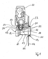
- Fig. 1 shows a mixing device 10 according to the invention in cross section, wherein in Fig. 1 In addition to the mixing device 10 according to the invention, a gas control device 11 and a support plate 12 of a blower are also shown.
- a housing and a Venturi nozzle of the mixing device 10 are formed as an integral and therefore monolithic unit.
- the housing of the mixing device 10 is in Fig. 1 by a reference numeral 13, the Venturi nozzle visualized by a reference numeral 14.
- the monolithic unit of housing 13 and Venturi nozzle 14 forms a flow channel for gas and combustion air.
- combustion air is sucked.
- the fan engages with the support plate 12 and provides a suction pressure to suck at the outlet 16, the mixture of gas and combustion air.
- a recess is made in a section between the inlet opening 15 and the outlet opening 16, in which a gas outlet 17 of the gas control device 11 engages.
- This recess is extended by a gas guide channel 18 which extends in between the inlet opening 15 and the outlet opening 16 Flow channel opens and thus initiates the fuel gas through an opening radially into the flow channel opening.
- the monolithic unit of housing 13 and Venturi nozzle 14 is formed from a plastic.
- the plastic formed, monolithic unit of housing 13 and Venturi nozzle 14 is attached to the metallic support plate 12 of the blower, in the sense of the present invention via a trained as a bayonet lock 19 quick release.
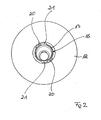
- These are, like the Fig. 2 can be removed, introduced into the support plate 12 recesses 20, in which correspondingly configured projections or cams 21 of the housing 13 of the mixing device 10 are inserted.
- the projections 21 are assigned to the outlet end of the monolithic unit of housing 13 and Venturi nozzle 14.
- the projections 21 secure the mixing device 10 in position on the support plate 12 of the blower.
- the bayonet closure 19 thus serves the fast, releasable fastening of the mixing device 10 to the support plate 12 of the blower.
- the attachment can be done without additional aids.
- the connection between mixing device 10 and blower is therefore reversible and can be solved again.
- Fig. 1 can be removed, the depth of insertion of the outlet end of the monolithic unit of housing 13 and Venturi nozzle 14 is limited in the support plate 12 of the blower by a stop 22.
- Fig. 1 can still be removed, the attachment of the monolithic unit from the housing 13 and the Venturi nozzle 14 is sealed to the support plate 12 of the blower by a sealing device 23.
- the sealing device 23 is designed as a so-called O-ring and ensures the Tightness of the connection over a longer period of operation, within which material change or deformations of the mixing device 10 made of plastic can be adjusted.
- the gas control device 11 is also attached via a quick release to the monolithic unit of housing 13 and Venturi nozzle 14.
- the gas regulator 11 with the gas outlet nozzle 17 engages in the corresponding recess within the monolithic unit for fastening the gas control device 11 to the monolithic unit.
- a monolithic unit associated securing bracket 24 in the sense of a snap at least partially the gas outlet 17 also the connection of the gas control device 11 with the monolithic unit of housing 13 and Venturi nozzle 14 may accordingly done without aids.
- sealing device 25 is also designed as a so-called O-ring and ensures a permanent sealing of the detachable connection between gas control device 11 and mixing device 10.
- a gas nozzle 26 is positioned in the region of the gas outlet 17.
- the gas nozzle 26 is designed as a separate component and protrudes into the gas outlet 17.
- a mixing device for a gas burner in which the Venturi nozzle 14 is an integral part of the housing 13.
- the monolithic unit of housing 13 and Venturi nozzle 14 is preferably made of a plastic.
- a gas regulator 11 engages with a gas outlet 17 in a recess of the mixing device 10 according to the invention, wherein the connection of gas control device 11 and mixing device 10, namely monolithic unit of housing 13 and Venturi nozzle 14, via a snap closure.
Landscapes
- Engineering & Computer Science (AREA)
- Chemical & Material Sciences (AREA)
- Combustion & Propulsion (AREA)
- Mechanical Engineering (AREA)
- General Engineering & Computer Science (AREA)
- Gas Burners (AREA)
Description
- Die Erfindung betrifft eine Mischvorrichtung zum Mischen von Gas und Verbrennungsluft für einen Gasbrenner nach dem Oberbegriff des Anspruchs 1. Des weiteren betrifft die Erfindung einen Gasbrenner nach dem Oberbegriff des Anspruchs 12.
- Zum Mischen zweier gasförmiger Medien, insbesondere von Verbrennungsluft und Brenngas, für einen Brenner werden Mischvorrichtungen mit einer Venturi-Düse verwendet. So offenbart die
DE 197 29 047 C1 eine Mischvorrichtung für einen Gasbrenner zur Erzeugung eines Gemisches aus Gas und Verbrennungsluft, die ein Gehäuse sowie eine separat ausgebildete Venturi-Düse aufweist. Die Mischvorrichtung nach dem Stand der Technik ist demnach zumindest zweiteilig ausgebildet, wobei die Venturi-Düse und das Gehäuse als separate Baugruppen ausgeführt sind. Nach dem Stand der Technik ist dabei das Gehäuse der Mischvorrichtung aus einem metallischen Werkstoff und die Venturi-Düse aus einem Kunststoff gebildet. Gemäß derDE 197 29 047 C1 sind die Venturi-Düse sowie das Gehäuse der Mischvorrichtung getrennt voneinander an einer Tragplatte eines Gebläses befestigt. Durch die mehrteilige Ausführung der Mischvorrichtung erhöhen sich Montageaufwand, Produktionsaufwand sowie Fertigungskosten. - Eine Mischvorrichtung gemäß dem Oberbegriff des Anspruchs 1 ist bekannt aus der
DE 295 06 691 U1 . Hinsichtlich weiteren Standes der Technik wird auf dieDE 197 47 481 C1 , auf dieDE 100 03 650 A1 , auf dieDE 42 24 212 A1 , auf dieNL 1 000 129 A1 FR 2 794 521 A - Hiervon ausgehend liegt der vorliegenden Erfindung das Problem zu Grunde, eine neuartige Mischvorrichtung zum Mischen von Gas und Verbrennungsluft für einen Gasbrenner sowie einen neuartigen Gasbrenner zu schaffen.
- Dieses Problem wird durch eine Mischvorrichtung zum Mischen von Gas und Verbrennungsluft für einen Gasbrenner mit den Merkmalen des Anspruchs 1 gelöst. Erfindungsgemäß greift an der monolithischen Einheit aus Gehäuse und Venturi-Düse ein Gasregelgerät an, wobei ein Gasauslassstutzen des Gasregelgeräts in eine entsprechende Ausnehmung der monolithischen Einheit einsteckbar ist.
- Im Sinne der hier vorliegenden Erfindung wird vorgeschlagen, die Venturi-Düse in das Gehäuse der Mischvorrichtung derart zu integrieren, dass das Gehäuse sowie die Venturi-Düse als monolithische Einheit ausgebildet sind. An der monolithischen Einheit aus Gehäuse und Venturi-Düse greift ein Gasregelgerät an, wobei ein Gasauslassstutzen des Gasregelgeräts in eine entsprechende Ausnehmung der monolithischen Einheit einsteckbar ist. Hierdurch wird die Anzahl der zu fertigen Baugruppen reduziert. Dies minimiert den Produktionsaufwand, Montageaufwand sowie die Fertigungskosten.
- Nach einer bevorzugten Weiterbildung der Erfindung ist die monolithische, aus Kunststoff gebildete Einheit aus Gehäuse und Venturi-Düse an einer metallischen Tragplatte des Gebläses über einen Bajonettverschluss befestigt ist. Das Gasregelgerät ist an der monolithischen Einheit aus Gehäuse und Venturi-Düse vorzugsweise über einen Schnappverschluss befestigt.
- Der erfindungsgemäße Gasbrenner ist in Anspruch 12 definiert.
- Bevorzugte Weiterbildungen der Erfindung ergeben sich aus den Unteransprüchen und der nachfolgenden Beschreibung. Nachfolgend wird ein Ausführungsbeispiel der Erfindung, ohne hierauf beschränkt zu sein, anhand der Zeichnung näher erläutert. In der Zeichnung zeigt:
- Fig. 1:
- eine erfindungsgemäße Mischvorrichtung zum Mischen von Gas und Verbrennungsluft für einen Gasbrenner zusammen mit einem Gasregelgerät und einer Montageplatte eines Gebläses im Querschnitt; und
- Fig. 2:
- die erfindungsgemäße Mischvorrichtung zum Mischen von Gas und Verbrennungsluft für einen Gasbrenner in einer aus der Zeichenebene gemäß
Fig. 1 um 90° herausgedrehten Ansicht, jedoch ohne das Gasregelgerät. - Nachfolgend wird die hier vorliegende Erfindung unter Bezugnahme auf
Fig. 1 und2 in größerem Detail beschrieben. -
Fig. 1 zeigt eine erfindungsgemäße Mischvorrichtung 10 im Querschnitt, wobei inFig. 1 neben der erfindungsgemäßen Mischvorrichtung 10 weiterhin ein Gasregelgerät 11 und eine Tragplatte 12 eines Gebläses dargestellt sind. Im Sinne der hier vorliegenden Erfindung sind ein Gehäuse sowie eine Venturi-Düse der Mischvorrichtung 10 als integrale und damit monolithische Einheit ausgebildet Das Gehäuse der Mischvorrichtung 10 ist inFig. 1 durch eine Bezugsziffer 13, die Venturi-Düse durch eine Bezugsziffer 14 visualisiert. - Die monolithische Einheit aus Gehäuse 13 und Venturi-Düse 14 bildet einen Strömungskanal für Gas- und Verbrennungsluft. An einer Einlassöffnung 15 dieses Strömungskanals ist Verbrennungsluft ansaugbar. An einer gegenüberliegenden Auslassöffnung 16 des Strömungskanals greift das Gebläse mit der Tragplatte 12 an und stellt einen Ansaugdruck bereit, um an der Auslassöffnung 16 das Gemisch aus Gas und Verbrennungsluft anzusaugen.
- In das Gehäuse 13 der Mischvorrichtung 10 ist in einen Abschnitt zwischen der Einlassöffnung 15 sowie der Auslassöffnung 16 eine Ausnehmung eingebracht, in weiche ein Gasauslassstutzen 17 des Gasregelgeräts 11 eingreift. Diese Ausnehmung wird durch einen Gasführungskanal 18 verlängert, der in den sich zwischen der Einlassöffnung 15 und der Auslassöffnung 16 erstreckenden Strömungskanal mündet und so das Brenngas durch eine radial in den Strömungskanal mündende Öffnung einleitet.
- Im Sinne der hier vorliegenden Erfindung ist die monolithische Einheit aus Gehäuse 13 und Venturi-Düse 14 aus einem Kunststoff gebildet. Die aus Kunststoff gebildete, monolithische Einheit aus Gehäuse 13 und Venturi-Düse 14 ist an der metallischen Tragplatte 12 des Gebläses befestigt, und zwar im Sinne der hier vorliegenden Erfindung über einen als Bajonettverschluss 19 ausgebildeten Schnellverschluss. Hierzu sind, wie der
Fig. 2 entnommen werden kann, in die Tragplatte 12 Ausnehmungen 20 eingebracht, in welche korrespondierend ausgestaltete Vorsprünge bzw. Nocken 21 des Gehäuses 13 der Mischvorrichtung 10 einführbar sind. Die Vorsprünge 21 sind dabei dem auslassseitigen Ende der monolithischen Einheit aus Gehäuse 13 und Venturi-Düse 14 zugeordnet. Nach dem Einführen der Vorsprünge 21 in die Ausnehmungen 20 der Tragplatte 12 sowie nach einer Relativdrehung zwischen der monolithischen Einheit und der Tragplatte 12 sichern die Vorsprünge 21 die Mischvorrichtung 10 in ihrer Position an der Tragplatte 12 des Gebläses. Der Bajonettverschluss 19 dient demnach dem schnellen, lösbaren Befestigen der Mischvorrichtung 10 an der Tragplatte 12 des Gebläses. Die Befestigung kann ohne zusätzliche Hilfsmittel erfolgen. Die Verbindung zwischen Mischvorrichtung 10 und Gebläse ist demnach reversibel und kann wieder gelöst werden. - Wie
Fig. 1 entnommen werden kann, wird die Einschiebtiefe des auslassseitigen Endes der monolithischen Einheit aus Gehäuse 13 und Venturi-Düse 14 in die Tragplatte 12 des Gebläses durch einen Anschlag 22 begrenzt. Der Anschlag 22 ist ebenso wie die Vorsprünge 21 dem auslassseitigen Ende des Gehäuse 13 zugeordnet. - Wie
Fig. 1 weiterhin entnommen werden kann, wird die Befestigung der monolithischen Einheit aus dem Gehäuse 13 und der Venturi-Düse 14 an der Tragplatte 12 des Gebläses durch eine Dichteinrichtung 23 abgedichtet. Die Dichteinrichtung 23 ist als sogenannter O-Ring ausgeführt und gewährleistet die Dichtheit der Verbindung auch über ein längere Betriebszeit, innerhalb derer sich Materialveränderung oder Deformationen der aus Kunststoff hergestellten Mischvorrichtung 10 einstellen können. - Das Gasregelgerät 11 ist ebenfalls über einen Schnellverschluss an der monolithischen Einheit aus Gehäuse 13 und Venturi-Düse 14 befestigt. Wie bereits erwähnt, greift zur Befestigung des Gasregelgeräts 11 an der monolithischen Einheit das Gasregelgerät 11 mit dem Gasauslassstutzen 17 in die entsprechende Ausnehmung innerhalb der monolithischen Einheit ein. Nach dem Einführen bzw. Einstecken des Gasauslassstutzens 17 in diese Ausnehmung umgreift ein der monolithischen Einheit zugeordneter Sicherungsbügel 24 im Sinne eines Schnappverschlusses zumindest abschnittsweise den Gasauslassstutzen 17. Auch die Verbindung des Gasregelgeräts 11 mit der monolithischen Einheit aus Gehäuse 13 und Venturi-Düse 14 kann demnach ohne Hilfsmittel erfolgen. Durch Zurückziehen bzw. Herausziehen des Sicherungsbügels 24 ist die Verbindung von Gasregelgerät 11 und monolithischer Einheit lösbar und das Gasregelgerät 11 ist von der monolithischen Einheit aus Gehäuse 13 und Venturi-Düse 14 trennbar bzw. aus derselben herausziehbar.
- Auch die Befestigung des Gasregelgeräts 11 über den Gasauslassstutzen 17 an der monolithischen Einheit aus Gehäuse 13 sowie Venturi-Düse 14 ist über eine Dichteinrichtung 25 abgedichtet. Auch diese Dichteinrichtung 25 ist als sogenannter O-Ring ausgeführt und sorgt für eine dauerhafte Abdichtung der lösbaren Verbindung zwischen Gasregelgerät 11 und Mischvorrichtung 10.
- Wie
Fig. 1 entnommen werden kann, ist im Bereich des Gasauslassstutzens 17 eine Gasdüse 26 positioniert. Die Gasdüse 26 ist als separates Bauteil ausgeführt und ragt in dem Gasauslassstutzen 17 hinein. - Im Sinne der hier vorliegenden Erfindung wird demnach eine Mischvorrichtung für einen Gasbrenner vorgeschlagen, bei der die Venturi-Düse 14 integraler Bestandteil des Gehäuses 13 ist. Die monolithische Einheit aus Gehäuse 13 und Venturi-Düse 14 ist dabei vorzugsweise aus einem Kunststoff hergestellt. Weiterhin liegt es im Sinne der hier vorliegenden Erfindung, die so ausgebildete Mischvorrichtung 10 über einen Bajonettverschluss an einer metallischen Tragplatte 12 eines Gebläses zu befestigen. Ein Gasregelgerät 11 greift mit einem Gasauslassstutzen 17 in eine Ausnehmung der erfindungsgemäßen Mischvorrichtung 10 ein, wobei die Verbindung von Gasregelgerät 11 und Mischvorrichtung 10, nämlicher monolithischer Einheit aus Gehäuse 13 sowie Venturi-Düse 14, über einen Schnappverschluss erfolgt.
-
- 10
- Mischvorrichtung
- 11
- Gasregelgerät
- 12
- Tragplatte
- 13
- Gehäuse
- 14
- Venturi-Düse
- 15
- Einlassöffnung
- 16
- Auslassöffnung
- 17
- Gasauslassstutzen
- 18
- Gasführungskanal
- 19
- Bajonettverschluss
- 20
- Ausnehmung
- 21
- Vorsprung
- 22
- Anschlag
- 23
- Dichteinrichtung
- 24
- Sicherungsbügel
- 25
- Dichteinrichtung
- 26
- Gasdüse
Claims (12)
- Mischvorrichtung zum Mischen von Gas und Verbrennungsluft für einen Gasbrenner, wobei die Mischvorrichtung (10) der Bereitstellung eines Gemischs aus Gas und Verbrennungsluft für einen Gasbrenner dient, welches demselben über ein Gebläse zuführbar ist, mit einem Gehäuse (13) und einer Venturi-Düse (14), wobei die Venturi-Düse (14) derart in das Gehäuse (13) integriert ist, dass das Gehäuse (13) und die Venturi-Düse (14) als monolithische Einheit ausgebildet sind, dadurch gekennzeichnet, dass an der monolithischen Einheit aus Gehäuse (13) und Venturi-Düse (14) ein Gasregelgerät (11) angreift, wobei ein Gasauslassstutzen (17) des Gasregelgeräts (11) in eine entsprechende Ausnehmung der monolithischen Einheit einsteckbar ist.
- Mischvorrichtung nach Anspruch 1, dadurch gekennzeichnet, dass die monolithische Einheit aus Gehäuse (13) und Venturi-Düse (14) aus Kunststoff gebildet ist.
- Mischvorrichtung nach Anspruch 1 oder 2, dadurch gekennzeichnet, dass die monolithische Einheit aus Gehäuse (13) und Venturi-Düse (14) einen Strömungskanal für Gas und Verbrennungsluft bildet, wobei an einer Einlassöffnung (15) desselben Verbrennungsluft ansaugbar ist, wobei an einer Auslassöffnung (16) desselben das Gebläse angreift, und wobei das Gebläse einen Ansaugdruck bereitstellt, um an der Auslassöffnung (16) das Gemisch aus Gas und Verbrennungsluft anzusaugen.
- Mischvorrichtung nach Anspruch 2 oder 3, dadurch gekennzeichnet, dass die monolithische, aus Kunststoff gebildete Einheit aus Gehäuse (13) und Venturi-Düse (14) an einer metallischen Tragplatte (12) des Gebläses befestigbar ist.
- Mischvorrichtung nach Anspruch 4, dadurch gekennzeichnet, dass die monolithische Einheit aus Gehäuse (13) und Venturi-Düse (14) an der Tragplatte (12) über einen Schnellverschluss befestigt ist.
- Mischvorrichtung nach Anspruch 5, dadurch gekennzeichnet, dass der Schnellverschluss als Bajonettverschluss (19) ausgebildet ist, wobei einem auslassseitigem Ende der monolithischen Einheit Vorsprünge (21) zugeordnet sind, die in entsprechende Ausnehmungen (20) innerhalb der Tragplatte (12) des Gebläses einführbar sind, und die nach einer Relativdrehung zwischen der monolithischen Einheit und der Tragplatte (12) die monolithischen Einheit an der Tragplatte (12) des Gebläses lösbar befestigen.
- Mischvorrichtung nach einem oder mehreren der Ansprüche 4 bis 6, dadurch gekennzeichnet, dass die Befestigung der monolithischen Einheit an der metallischen Tragplatte (12) des Gebläses über eine Dichteinrichtung (23) abgedichtet ist.
- Mischvorrichtung nach einem oder mehreren der Ansprüche 1 bis 7, dadurch gekennzeichnet, dass das Gasregelgerät (11) an der monolithischen Einheit aus Gehäuse (13) und Venturi-Düse (14) über einen Schnellverschluss befestigt ist.
- Mischvorrichtung nach Anspruch 8, dadurch gekennzeichnet, dass der Schnellverschluss als Schnappverschluss ausgebildet ist, wobei ein der monolithischen Einheit zugeordneter Sicherungsbügel (24) den Gasauslassstutzen (17) nach dem Einstecken desselben in die Ausnehmung zumindest abschnittsweise umgreift, um das Gasregelgerät (11) an der monolithischen Einheit lösbar zu befestigen.
- Mischvorrichtung nach einem oder mehreren der Ansprüche 1 bis 9, dadurch gekennzeichnet, dass die Befestigung des Gasregelgeräts (11) an der monolithischen Einheit über eine Dichteinrichtung (25) abgedichtet ist.
- Mischvorrichtung nach einem oder mehreren der Ansprüche 1 bis 10, dadurch gekennzeichnet, dass die Ausnehmung der monolithischen Einheit, an welcher das Gasregelgerät (11) angreift, zwischen der Einlassöffnung (15) und der Auslassöffnung (16) des von der monolithischen Einheit gebildeten Strömungskanals angeordnet ist.
- Gasbrenner, mit einer Brennkammer, wobei der Brennkammer ein Gemisch aus Gas und Verbrennungsluft über eine Gebläse zuführbar ist, und wobei das Gebläse an einer Mischvorrichtung (10) zum Mischen von Gas und Verbrennungsluft angreift, das von der Mischvorrichtung (10) bereitgestelltes Gemisch ansaugt und der Brennkammer zuführt, dadurch gekennzeichnet, dass die Mischvorrichtung (10) nach einem oder mehreren der Ansprüche 1 bis 11 ausgebildet ist.
Applications Claiming Priority (2)
| Application Number | Priority Date | Filing Date | Title |
|---|---|---|---|
| DE102004007123A DE102004007123B3 (de) | 2004-02-12 | 2004-02-12 | Mischvorrichtung zum Mischen von Gas und Verbrennungsluft für einen Gasbrenner sowie Gasbrenner |
| PCT/EP2005/001125 WO2005078343A1 (de) | 2004-02-12 | 2005-02-04 | Mischvorrichtung zum mischen von gas und verbrennungsluft für einen gasbrenner sowie gasbrenner |
Publications (2)
| Publication Number | Publication Date |
|---|---|
| EP1714079A1 EP1714079A1 (de) | 2006-10-25 |
| EP1714079B1 true EP1714079B1 (de) | 2015-07-29 |
Family
ID=34801904
Family Applications (1)
| Application Number | Title | Priority Date | Filing Date |
|---|---|---|---|
| EP05707196.1A Expired - Lifetime EP1714079B1 (de) | 2004-02-12 | 2005-02-04 | Mischvorrichtung zum mischen von gas und verbrennungsluft für einen gasbrenner sowie gasbrenner |
Country Status (4)
| Country | Link |
|---|---|
| US (1) | US20070243496A1 (de) |
| EP (1) | EP1714079B1 (de) |
| DE (1) | DE102004007123B3 (de) |
| WO (1) | WO2005078343A1 (de) |
Families Citing this family (12)
| Publication number | Priority date | Publication date | Assignee | Title |
|---|---|---|---|---|
| AT502650B1 (de) * | 2006-02-13 | 2007-05-15 | Vaillant Austria Gmbh | Aufnahmekörper in verbindung mit einer rohrleitung |
| DE102007004969A1 (de) | 2007-01-26 | 2008-07-31 | Viessmann Werke Gmbh & Co Kg | Mischeinrichtung für einen Gasgebläsebrenner |
| DE102007008460A1 (de) | 2007-02-19 | 2008-08-21 | Viessmann Werke Gmbh & Co Kg | Mischeinrichtung für einen Gasgebläsebrenner |
| EP2048439B1 (de) | 2007-10-12 | 2014-06-18 | ebm-papst Landshut GmbH | Radialgebläse mit integriertem Regelventil |
| DE102007053028B4 (de) * | 2007-11-05 | 2013-04-11 | Honeywell Technologies S.A.R.L. | Vorrichtung zur Bereitstellung eines Gas-/ Verbrennungsluft-Gemisches für einen Gasbrenner |
| DE102009048405A1 (de) | 2009-10-06 | 2011-04-07 | Honeywell Technologies S.A.R.L. | Regeleinrichtung für Gasbrenner |
| DE102010010791A1 (de) | 2010-03-09 | 2011-09-15 | Honeywell Technologies Sarl | Mischvorrichtung für einen Gasbrenner |
| DE102010044591B4 (de) | 2010-09-07 | 2024-11-14 | Pittway Sàrl | Gasregelgerät mit angebauter Venturi-Düse |
| DE102011014117A1 (de) | 2011-03-15 | 2012-09-20 | Ebm-Papst Landshut Gmbh | Mischvorrichtung zur Mischung von Verbrennungsluft und Gas für ein Gasgerät |
| EP3015767B1 (de) | 2014-10-29 | 2019-03-06 | Honeywell Technologies Sarl | Anordnung mit einem Gasventil und einem Gas-/Luftmischer |
| EP3015768B1 (de) | 2014-10-29 | 2019-02-20 | Honeywell Technologies Sarl | Anordnung mit einem Gasventil, einem Lüfter, einem Gas-/Luftmischer und einer Brennertür |
| DE102021108001A1 (de) | 2021-03-30 | 2022-10-06 | Vaillant Gmbh | Verfahren zur Befestigung einer Gasdüse an einem Gasventil, Gasdüse und Heizgerät |
Family Cites Families (41)
| Publication number | Priority date | Publication date | Assignee | Title |
|---|---|---|---|---|
| US2021241A (en) * | 1934-12-24 | 1935-11-19 | Mall Arthur William | Quick detachable coupling |
| US2771308A (en) * | 1954-02-23 | 1956-11-20 | Puritan Compressed Gas Corp | Quick connect valve |
| US3072390A (en) * | 1959-06-18 | 1963-01-08 | Tillotson Mfg Co | Charge forming method and apparatus |
| FR1461577A (fr) * | 1965-10-25 | 1966-02-25 | Sibe | Perfectionnements apportés aux dispositifs d'alimentation en combustible pour moteurs à explosion |
| US3538940A (en) * | 1967-09-15 | 1970-11-10 | Gra Tec Inc | Fitting assembly |
| US3574359A (en) * | 1969-07-22 | 1971-04-13 | Gen Motors Corp | Fluid conduit coupling |
| US3593967A (en) * | 1969-11-28 | 1971-07-20 | Borg Warner | Diaphragm carburetor having fuel channel system for engine idling and acceleration |
| US4033714A (en) * | 1972-04-17 | 1977-07-05 | Radiation Limited | Gaseous fuel burners |
| US4291658A (en) * | 1975-02-05 | 1981-09-29 | Nissan Motor Company, Limited | Automotive engine carburetor |
| NL181516C (nl) * | 1976-05-26 | 1987-09-01 | Tno | Inrichting voor het toevoeren van gasvormige brandstoffen, zoals lpg of aardgas aan een verbrandingsmotor. |
| US4128391A (en) * | 1977-02-14 | 1978-12-05 | Braunstein Lee G | Gas regulator and gas-fired torch assemblies |
| US4116476A (en) * | 1977-11-11 | 1978-09-26 | Porter Gary K | Quick disconnect coupler assembly |
| US4224019A (en) * | 1978-02-27 | 1980-09-23 | Westinghouse Electric Corp. | Power burner for compact furnace |
| US4283645A (en) * | 1978-10-06 | 1981-08-11 | Hofmann Kurt H | Electrical drive motor, in particular for water pumps in the field of aquaria |
| US4458719A (en) * | 1981-11-02 | 1984-07-10 | Imperial Clevite Inc. | Quick coupler service fitting |
| US4576359A (en) * | 1984-03-15 | 1986-03-18 | Hans Oetiker | Coupling for pressure gas lines |
| US4797072A (en) * | 1987-06-19 | 1989-01-10 | Shop-Vac Corporation | Portable electric blower |
| US4788962A (en) * | 1987-10-05 | 1988-12-06 | Mashburn James S | Cantilevered gas barbecue |
| FR2622470B1 (fr) * | 1987-11-03 | 1991-05-10 | Elf France | Dispositif de dispersion de gaz au sein d'une phase liquide et application de ce dispositif a la realisation de traitements comportant le transfert d'une phase gazeuse dans une phase liquide |
| US4894067A (en) * | 1987-11-18 | 1990-01-16 | Carbumatic B.V. | Low profile gaseous fuel carburetor |
| US4830600A (en) * | 1988-01-19 | 1989-05-16 | American Standard Inc. | Premix furnace burner |
| US5152276A (en) * | 1990-12-27 | 1992-10-06 | Maytag Corporation | Sealed gas burner assembly |
| US5150880A (en) * | 1991-02-14 | 1992-09-29 | Austin Jr George K | Valve assembly with flow control |
| US5445516A (en) * | 1991-06-06 | 1995-08-29 | Bowles Fluidics Corporation | Burner method and apparatus having low emissions |
| DE4224212A1 (de) * | 1991-07-22 | 1993-01-28 | Vaillant Joh Gmbh & Co | Doppelwandiger heizschacht |
| US5370527A (en) * | 1992-10-28 | 1994-12-06 | The Coleman Company, Inc. | Fuel tube for burner assembly with remote fuel tank |
| US5431557A (en) * | 1993-12-16 | 1995-07-11 | Teledyne Industries, Inc. | Low NOX gas combustion systems |
| NL1000129C1 (en) * | 1995-04-12 | 1996-05-13 | Atag Verwarming Bv | Central heating boiler fired by gas - has forced gas and air mixing venturi system controlled by electronic circuit |
| DE29506691U1 (de) * | 1995-04-20 | 1996-08-29 | Papst-Motoren GmbH & Co KG, 78112 St Georgen | Brennergebläse mit Radiallaufrad |
| US5827335A (en) * | 1995-11-07 | 1998-10-27 | Pioneer/Eclipse Corporation | Enhanced performance carburetor system |
| IT1288006B1 (it) * | 1996-12-06 | 1998-09-10 | Sit La Precisa Spa | Dispositivo miscelatore aria-gas in particolare per bruciatori a gas con ventilazione forzata. |
| DE19729047C1 (de) * | 1997-07-08 | 1998-09-24 | Honeywell Bv | Mischvorrichtung zur Erzeugung eines Gemisches aus Gas und Verbrennungsluft für einen Brenner |
| DE19733768C2 (de) * | 1997-08-05 | 2003-06-26 | Dungs Karl Gmbh & Co | Brenngas-Einleitungsvorrichtung für einen Gas-Vormischbrenner |
| EP0908682B1 (de) * | 1997-10-08 | 2002-04-17 | SABAF S.p.A. | Gasbrenner für Haushaltsgeräte |
| DE19747481C1 (de) * | 1997-10-28 | 1999-04-29 | Bosch Gmbh Robert | Gasbrenner mit einem Brennerkörper und einem Basisteil |
| DE19833540C2 (de) * | 1998-07-25 | 2000-06-29 | Stihl Maschf Andreas | Membranvergaser |
| DE19907556B4 (de) * | 1998-09-02 | 2007-10-25 | BSH Bosch und Siemens Hausgeräte GmbH | Flüssigkeitspumpe, insbesondere Laugenpumpe für Haushaltgeräte |
| FR2794521B1 (fr) * | 1999-06-04 | 2001-07-13 | Geminox | Bruleur a gaz a ventilation forcee pour chaudiere |
| DE10003650A1 (de) * | 2000-01-28 | 2001-08-16 | Viessmann Werke Kg | Atmosphärischer Gasbrenner |
| DE10015920A1 (de) * | 2000-03-30 | 2001-08-30 | Xcellsis Gmbh | Strömungskörper, Verfahren zu dessen Herstellung und Verwendung desselben |
| ITUD20030162A1 (it) * | 2003-07-30 | 2005-01-31 | Invensys Controls Italy Srl | Pompa elettromagnetica a nucleo oscillante. |
-
2004
- 2004-02-12 DE DE102004007123A patent/DE102004007123B3/de not_active Expired - Fee Related
-
2005
- 2005-02-04 US US10/597,927 patent/US20070243496A1/en not_active Abandoned
- 2005-02-04 WO PCT/EP2005/001125 patent/WO2005078343A1/de not_active Ceased
- 2005-02-04 EP EP05707196.1A patent/EP1714079B1/de not_active Expired - Lifetime
Also Published As
| Publication number | Publication date |
|---|---|
| WO2005078343A1 (de) | 2005-08-25 |
| EP1714079A1 (de) | 2006-10-25 |
| DE102004007123B3 (de) | 2005-08-18 |
| US20070243496A1 (en) | 2007-10-18 |
Similar Documents
| Publication | Publication Date | Title |
|---|---|---|
| DE102004007123B3 (de) | Mischvorrichtung zum Mischen von Gas und Verbrennungsluft für einen Gasbrenner sowie Gasbrenner | |
| DE69732182T2 (de) | Brennstoff-luft-mischgerät | |
| EP3101184B1 (de) | Sanitäre einsetzeinheit | |
| EP1959194B1 (de) | Mischeinrichtung für einen Gasgebläsebrenner | |
| EP1527269B1 (de) | Saugstrahlpumpe | |
| WO2015158454A1 (de) | Kraftstofffördervorrichtung für einen satteltank | |
| EP2426413B1 (de) | Gasregelgerät mit angebauter Venturi-Düse | |
| DE102004063459A1 (de) | Brennkraftmaschine mit Frischluftanlage und Entlüftungseinrichtung | |
| DE19940387C1 (de) | Leckageanschluss und Kraftstoffinjektor mit einem solchen Leckageanschluss | |
| DE4301655C1 (de) | Ventilanordnung für eine Abgasrückführung bei einem Verbrennungsmotor | |
| EP1931859B1 (de) | Leitschaufel-anordnung einer strömungsmaschine | |
| DE102009001564B4 (de) | Drosselelement | |
| EP2825738B1 (de) | Einspritzvorrichtung | |
| DE19530963A1 (de) | Gasbrenner und Verfahren zum Betreiben des Gasbrenners | |
| DE102019129366B4 (de) | Antriebseinrichtung mit einer Brennkraftmaschine und einem Verdichter | |
| DE2609987C2 (de) | Brenner für flüssige oder gasförmige Brennstoffe | |
| DE10008795B4 (de) | Bremskraftverstärker für ein Kraftfahrzeug | |
| EP1953453A1 (de) | Mischeinrichtung für einen Gasgebläsebrenner | |
| DE102008019157B4 (de) | Verbrennungsmotor und Verfahren zu dessen Betrieb | |
| DE10203600B4 (de) | Leckageanschluss zum Anbringen einer Leckageleitung an einen Kraftstoffinjektor | |
| EP1861625B1 (de) | Saugstrahlpumpe | |
| WO2009065679A1 (de) | Kraftstoffeinspritzvorrichtung | |
| DE102015011864B4 (de) | Saugstrahlpumpeneinrichtung, Saugstrahlpumpenmontagesatz, Verfahren zum Herstellen wenigstens einer Saugstrahlpumpeneinrichtung sowie Fluidtankanordnung | |
| EP3289198B1 (de) | Turbolader mit verdichteranordnung | |
| DE102005059457B4 (de) | Standheizung sowie ein hierfür bestimmtes Saugrohr |
Legal Events
| Date | Code | Title | Description |
|---|---|---|---|
| PUAI | Public reference made under article 153(3) epc to a published international application that has entered the european phase |
Free format text: ORIGINAL CODE: 0009012 |
|
| 17P | Request for examination filed |
Effective date: 20060707 |
|
| AK | Designated contracting states |
Kind code of ref document: A1 Designated state(s): AT BE BG CH CY CZ DE DK EE ES FI FR GB GR HU IE IS IT LI LT LU MC NL PL PT RO SE SI SK TR |
|
| DAX | Request for extension of the european patent (deleted) | ||
| RAP1 | Party data changed (applicant data changed or rights of an application transferred) |
Owner name: HONEYWELL TECHNOLOGIES SARL |
|
| 17Q | First examination report despatched |
Effective date: 20110909 |
|
| GRAP | Despatch of communication of intention to grant a patent |
Free format text: ORIGINAL CODE: EPIDOSNIGR1 |
|
| INTG | Intention to grant announced |
Effective date: 20150310 |
|
| GRAS | Grant fee paid |
Free format text: ORIGINAL CODE: EPIDOSNIGR3 |
|
| GRAA | (expected) grant |
Free format text: ORIGINAL CODE: 0009210 |
|
| AK | Designated contracting states |
Kind code of ref document: B1 Designated state(s): AT BE BG CH CY CZ DE DK EE ES FI FR GB GR HU IE IS IT LI LT LU MC NL PL PT RO SE SI SK TR |
|
| REG | Reference to a national code |
Ref country code: GB Ref legal event code: FG4D Free format text: NOT ENGLISH |
|
| REG | Reference to a national code |
Ref country code: CH Ref legal event code: EP |
|
| REG | Reference to a national code |
Ref country code: AT Ref legal event code: REF Ref document number: 739628 Country of ref document: AT Kind code of ref document: T Effective date: 20150815 |
|
| REG | Reference to a national code |
Ref country code: IE Ref legal event code: FG4D Free format text: LANGUAGE OF EP DOCUMENT: GERMAN |
|
| REG | Reference to a national code |
Ref country code: DE Ref legal event code: R096 Ref document number: 502005014874 Country of ref document: DE |
|
| REG | Reference to a national code |
Ref country code: LT Ref legal event code: MG4D |
|
| REG | Reference to a national code |
Ref country code: NL Ref legal event code: MP Effective date: 20150729 |
|
| REG | Reference to a national code |
Ref country code: FR Ref legal event code: PLFP Year of fee payment: 12 |
|
| PG25 | Lapsed in a contracting state [announced via postgrant information from national office to epo] |
Ref country code: GR Free format text: LAPSE BECAUSE OF FAILURE TO SUBMIT A TRANSLATION OF THE DESCRIPTION OR TO PAY THE FEE WITHIN THE PRESCRIBED TIME-LIMIT Effective date: 20151030 Ref country code: LT Free format text: LAPSE BECAUSE OF FAILURE TO SUBMIT A TRANSLATION OF THE DESCRIPTION OR TO PAY THE FEE WITHIN THE PRESCRIBED TIME-LIMIT Effective date: 20150729 Ref country code: FI Free format text: LAPSE BECAUSE OF FAILURE TO SUBMIT A TRANSLATION OF THE DESCRIPTION OR TO PAY THE FEE WITHIN THE PRESCRIBED TIME-LIMIT Effective date: 20150729 |
|
| PG25 | Lapsed in a contracting state [announced via postgrant information from national office to epo] |
Ref country code: SE Free format text: LAPSE BECAUSE OF FAILURE TO SUBMIT A TRANSLATION OF THE DESCRIPTION OR TO PAY THE FEE WITHIN THE PRESCRIBED TIME-LIMIT Effective date: 20150729 Ref country code: IS Free format text: LAPSE BECAUSE OF FAILURE TO SUBMIT A TRANSLATION OF THE DESCRIPTION OR TO PAY THE FEE WITHIN THE PRESCRIBED TIME-LIMIT Effective date: 20151129 Ref country code: PT Free format text: LAPSE BECAUSE OF FAILURE TO SUBMIT A TRANSLATION OF THE DESCRIPTION OR TO PAY THE FEE WITHIN THE PRESCRIBED TIME-LIMIT Effective date: 20151130 Ref country code: ES Free format text: LAPSE BECAUSE OF FAILURE TO SUBMIT A TRANSLATION OF THE DESCRIPTION OR TO PAY THE FEE WITHIN THE PRESCRIBED TIME-LIMIT Effective date: 20150729 Ref country code: PL Free format text: LAPSE BECAUSE OF FAILURE TO SUBMIT A TRANSLATION OF THE DESCRIPTION OR TO PAY THE FEE WITHIN THE PRESCRIBED TIME-LIMIT Effective date: 20150729 |
|
| PG25 | Lapsed in a contracting state [announced via postgrant information from national office to epo] |
Ref country code: NL Free format text: LAPSE BECAUSE OF FAILURE TO SUBMIT A TRANSLATION OF THE DESCRIPTION OR TO PAY THE FEE WITHIN THE PRESCRIBED TIME-LIMIT Effective date: 20150729 |
|
| PG25 | Lapsed in a contracting state [announced via postgrant information from national office to epo] |
Ref country code: CZ Free format text: LAPSE BECAUSE OF FAILURE TO SUBMIT A TRANSLATION OF THE DESCRIPTION OR TO PAY THE FEE WITHIN THE PRESCRIBED TIME-LIMIT Effective date: 20150729 Ref country code: DK Free format text: LAPSE BECAUSE OF FAILURE TO SUBMIT A TRANSLATION OF THE DESCRIPTION OR TO PAY THE FEE WITHIN THE PRESCRIBED TIME-LIMIT Effective date: 20150729 Ref country code: IT Free format text: LAPSE BECAUSE OF FAILURE TO SUBMIT A TRANSLATION OF THE DESCRIPTION OR TO PAY THE FEE WITHIN THE PRESCRIBED TIME-LIMIT Effective date: 20150729 Ref country code: EE Free format text: LAPSE BECAUSE OF FAILURE TO SUBMIT A TRANSLATION OF THE DESCRIPTION OR TO PAY THE FEE WITHIN THE PRESCRIBED TIME-LIMIT Effective date: 20150729 Ref country code: SK Free format text: LAPSE BECAUSE OF FAILURE TO SUBMIT A TRANSLATION OF THE DESCRIPTION OR TO PAY THE FEE WITHIN THE PRESCRIBED TIME-LIMIT Effective date: 20150729 |
|
| REG | Reference to a national code |
Ref country code: DE Ref legal event code: R097 Ref document number: 502005014874 Country of ref document: DE |
|
| PG25 | Lapsed in a contracting state [announced via postgrant information from national office to epo] |
Ref country code: RO Free format text: LAPSE BECAUSE OF FAILURE TO SUBMIT A TRANSLATION OF THE DESCRIPTION OR TO PAY THE FEE WITHIN THE PRESCRIBED TIME-LIMIT Effective date: 20150729 Ref country code: BE Free format text: LAPSE BECAUSE OF NON-PAYMENT OF DUE FEES Effective date: 20160229 |
|
| PLBE | No opposition filed within time limit |
Free format text: ORIGINAL CODE: 0009261 |
|
| STAA | Information on the status of an ep patent application or granted ep patent |
Free format text: STATUS: NO OPPOSITION FILED WITHIN TIME LIMIT |
|
| 26N | No opposition filed |
Effective date: 20160502 |
|
| PG25 | Lapsed in a contracting state [announced via postgrant information from national office to epo] |
Ref country code: SI Free format text: LAPSE BECAUSE OF FAILURE TO SUBMIT A TRANSLATION OF THE DESCRIPTION OR TO PAY THE FEE WITHIN THE PRESCRIBED TIME-LIMIT Effective date: 20150729 |
|
| PG25 | Lapsed in a contracting state [announced via postgrant information from national office to epo] |
Ref country code: MC Free format text: LAPSE BECAUSE OF FAILURE TO SUBMIT A TRANSLATION OF THE DESCRIPTION OR TO PAY THE FEE WITHIN THE PRESCRIBED TIME-LIMIT Effective date: 20150729 Ref country code: LU Free format text: LAPSE BECAUSE OF FAILURE TO SUBMIT A TRANSLATION OF THE DESCRIPTION OR TO PAY THE FEE WITHIN THE PRESCRIBED TIME-LIMIT Effective date: 20160204 |
|
| REG | Reference to a national code |
Ref country code: CH Ref legal event code: PL |
|
| PG25 | Lapsed in a contracting state [announced via postgrant information from national office to epo] |
Ref country code: LI Free format text: LAPSE BECAUSE OF NON-PAYMENT OF DUE FEES Effective date: 20160229 Ref country code: CH Free format text: LAPSE BECAUSE OF NON-PAYMENT OF DUE FEES Effective date: 20160229 |
|
| REG | Reference to a national code |
Ref country code: IE Ref legal event code: MM4A |
|
| REG | Reference to a national code |
Ref country code: FR Ref legal event code: PLFP Year of fee payment: 13 |
|
| PG25 | Lapsed in a contracting state [announced via postgrant information from national office to epo] |
Ref country code: IE Free format text: LAPSE BECAUSE OF NON-PAYMENT OF DUE FEES Effective date: 20160204 |
|
| REG | Reference to a national code |
Ref country code: AT Ref legal event code: MM01 Ref document number: 739628 Country of ref document: AT Kind code of ref document: T Effective date: 20160204 |
|
| PG25 | Lapsed in a contracting state [announced via postgrant information from national office to epo] |
Ref country code: AT Free format text: LAPSE BECAUSE OF NON-PAYMENT OF DUE FEES Effective date: 20160204 |
|
| REG | Reference to a national code |
Ref country code: FR Ref legal event code: PLFP Year of fee payment: 14 |
|
| PG25 | Lapsed in a contracting state [announced via postgrant information from national office to epo] |
Ref country code: HU Free format text: LAPSE BECAUSE OF FAILURE TO SUBMIT A TRANSLATION OF THE DESCRIPTION OR TO PAY THE FEE WITHIN THE PRESCRIBED TIME-LIMIT; INVALID AB INITIO Effective date: 20050204 Ref country code: CY Free format text: LAPSE BECAUSE OF FAILURE TO SUBMIT A TRANSLATION OF THE DESCRIPTION OR TO PAY THE FEE WITHIN THE PRESCRIBED TIME-LIMIT Effective date: 20150729 |
|
| PG25 | Lapsed in a contracting state [announced via postgrant information from national office to epo] |
Ref country code: TR Free format text: LAPSE BECAUSE OF FAILURE TO SUBMIT A TRANSLATION OF THE DESCRIPTION OR TO PAY THE FEE WITHIN THE PRESCRIBED TIME-LIMIT Effective date: 20150729 |
|
| PG25 | Lapsed in a contracting state [announced via postgrant information from national office to epo] |
Ref country code: BG Free format text: LAPSE BECAUSE OF FAILURE TO SUBMIT A TRANSLATION OF THE DESCRIPTION OR TO PAY THE FEE WITHIN THE PRESCRIBED TIME-LIMIT Effective date: 20150729 |
|
| PGFP | Annual fee paid to national office [announced via postgrant information from national office to epo] |
Ref country code: GB Payment date: 20200226 Year of fee payment: 16 |
|
| PGFP | Annual fee paid to national office [announced via postgrant information from national office to epo] |
Ref country code: FR Payment date: 20200225 Year of fee payment: 16 |
|
| GBPC | Gb: european patent ceased through non-payment of renewal fee |
Effective date: 20210204 |
|
| PG25 | Lapsed in a contracting state [announced via postgrant information from national office to epo] |
Ref country code: FR Free format text: LAPSE BECAUSE OF NON-PAYMENT OF DUE FEES Effective date: 20210228 Ref country code: GB Free format text: LAPSE BECAUSE OF NON-PAYMENT OF DUE FEES Effective date: 20210204 |
|
| P01 | Opt-out of the competence of the unified patent court (upc) registered |
Effective date: 20230602 |
|
| PGFP | Annual fee paid to national office [announced via postgrant information from national office to epo] |
Ref country code: DE Payment date: 20240328 Year of fee payment: 20 |
|
| REG | Reference to a national code |
Ref country code: DE Ref legal event code: R071 Ref document number: 502005014874 Country of ref document: DE |