EP1527269B1 - Saugstrahlpumpe - Google Patents
Saugstrahlpumpe Download PDFInfo
- Publication number
- EP1527269B1 EP1527269B1 EP20030792114 EP03792114A EP1527269B1 EP 1527269 B1 EP1527269 B1 EP 1527269B1 EP 20030792114 EP20030792114 EP 20030792114 EP 03792114 A EP03792114 A EP 03792114A EP 1527269 B1 EP1527269 B1 EP 1527269B1
- Authority
- EP
- European Patent Office
- Prior art keywords
- jet pump
- pot
- suction jet
- suction
- mixing tube
- Prior art date
- Legal status (The legal status is an assumption and is not a legal conclusion. Google has not performed a legal analysis and makes no representation as to the accuracy of the status listed.)
- Expired - Lifetime
Links
Images


Classifications
-
- F—MECHANICAL ENGINEERING; LIGHTING; HEATING; WEAPONS; BLASTING
- F04—POSITIVE - DISPLACEMENT MACHINES FOR LIQUIDS; PUMPS FOR LIQUIDS OR ELASTIC FLUIDS
- F04F—PUMPING OF FLUID BY DIRECT CONTACT OF ANOTHER FLUID OR BY USING INERTIA OF FLUID TO BE PUMPED; SIPHONS
- F04F5/00—Jet pumps, i.e. devices in which flow is induced by pressure drop caused by velocity of another fluid flow
- F04F5/02—Jet pumps, i.e. devices in which flow is induced by pressure drop caused by velocity of another fluid flow the inducing fluid being liquid
-
- F—MECHANICAL ENGINEERING; LIGHTING; HEATING; WEAPONS; BLASTING
- F04—POSITIVE - DISPLACEMENT MACHINES FOR LIQUIDS; PUMPS FOR LIQUIDS OR ELASTIC FLUIDS
- F04F—PUMPING OF FLUID BY DIRECT CONTACT OF ANOTHER FLUID OR BY USING INERTIA OF FLUID TO BE PUMPED; SIPHONS
- F04F5/00—Jet pumps, i.e. devices in which flow is induced by pressure drop caused by velocity of another fluid flow
- F04F5/44—Component parts, details, or accessories not provided for in, or of interest apart from, groups F04F5/02 - F04F5/42
-
- F—MECHANICAL ENGINEERING; LIGHTING; HEATING; WEAPONS; BLASTING
- F02—COMBUSTION ENGINES; HOT-GAS OR COMBUSTION-PRODUCT ENGINE PLANTS
- F02M—SUPPLYING COMBUSTION ENGINES IN GENERAL WITH COMBUSTIBLE MIXTURES OR CONSTITUENTS THEREOF
- F02M37/00—Apparatus or systems for feeding liquid fuel from storage containers to carburettors or fuel-injection apparatus; Arrangements for purifying liquid fuel specially adapted for, or arranged on, internal-combustion engines
- F02M37/02—Feeding by means of suction apparatus, e.g. by air flow through carburettors
- F02M37/025—Feeding by means of a liquid fuel-driven jet pump
-
- F—MECHANICAL ENGINEERING; LIGHTING; HEATING; WEAPONS; BLASTING
- F02—COMBUSTION ENGINES; HOT-GAS OR COMBUSTION-PRODUCT ENGINE PLANTS
- F02M—SUPPLYING COMBUSTION ENGINES IN GENERAL WITH COMBUSTIBLE MIXTURES OR CONSTITUENTS THEREOF
- F02M37/00—Apparatus or systems for feeding liquid fuel from storage containers to carburettors or fuel-injection apparatus; Arrangements for purifying liquid fuel specially adapted for, or arranged on, internal-combustion engines
- F02M37/04—Feeding by means of driven pumps
- F02M37/08—Feeding by means of driven pumps electrically driven
- F02M37/10—Feeding by means of driven pumps electrically driven submerged in fuel, e.g. in reservoir
- F02M37/106—Feeding by means of driven pumps electrically driven submerged in fuel, e.g. in reservoir the pump being installed in a sub-tank
-
- F—MECHANICAL ENGINEERING; LIGHTING; HEATING; WEAPONS; BLASTING
- F04—POSITIVE - DISPLACEMENT MACHINES FOR LIQUIDS; PUMPS FOR LIQUIDS OR ELASTIC FLUIDS
- F04F—PUMPING OF FLUID BY DIRECT CONTACT OF ANOTHER FLUID OR BY USING INERTIA OF FLUID TO BE PUMPED; SIPHONS
- F04F5/00—Jet pumps, i.e. devices in which flow is induced by pressure drop caused by velocity of another fluid flow
- F04F5/02—Jet pumps, i.e. devices in which flow is induced by pressure drop caused by velocity of another fluid flow the inducing fluid being liquid
- F04F5/10—Jet pumps, i.e. devices in which flow is induced by pressure drop caused by velocity of another fluid flow the inducing fluid being liquid displacing liquids, e.g. containing solids, or liquids and elastic fluids
-
- F—MECHANICAL ENGINEERING; LIGHTING; HEATING; WEAPONS; BLASTING
- F04—POSITIVE - DISPLACEMENT MACHINES FOR LIQUIDS; PUMPS FOR LIQUIDS OR ELASTIC FLUIDS
- F04F—PUMPING OF FLUID BY DIRECT CONTACT OF ANOTHER FLUID OR BY USING INERTIA OF FLUID TO BE PUMPED; SIPHONS
- F04F5/00—Jet pumps, i.e. devices in which flow is induced by pressure drop caused by velocity of another fluid flow
- F04F5/54—Installations characterised by use of jet pumps, e.g. combinations of two or more jet pumps of different type
-
- Y—GENERAL TAGGING OF NEW TECHNOLOGICAL DEVELOPMENTS; GENERAL TAGGING OF CROSS-SECTIONAL TECHNOLOGIES SPANNING OVER SEVERAL SECTIONS OF THE IPC; TECHNICAL SUBJECTS COVERED BY FORMER USPC CROSS-REFERENCE ART COLLECTIONS [XRACs] AND DIGESTS
- Y10—TECHNICAL SUBJECTS COVERED BY FORMER USPC
- Y10T—TECHNICAL SUBJECTS COVERED BY FORMER US CLASSIFICATION
- Y10T137/00—Fluid handling
- Y10T137/8593—Systems
- Y10T137/85978—With pump
- Y10T137/86075—And jet-aspiration type pump
Definitions
- the invention relates to a suction jet pump with a propulsion jet nozzle, a mixing tube, a suction port and a suction line connected thereto.
- the suction jet pump serves to convey fuel within a fuel tank or from a fuel tank in a surge pot disposed within the fuel tank.
- suction jet pumps are used to supply the fuel present in other areas of the fuel tank to the delivery unit or to deliver the fuel at least into the chamber or the area in which the delivery unit is located.
- a suction jet pump is for example from the DE 37 32 415 A1 known, which discloses all the features of the preamble of claim 1.
- suction jet pumps are arranged at the bottom of the chambers or the areas of the fuel tank, from which the fuel is to be conveyed to the delivery unit.
- suction jet pump With the arrangement of the suction of the suction jet pump at the bottom of the fuel tank, the suction jet pump is always in the fuel and is therefore always ready for use. Such suction jet pumps pay off by a good Efficiency.
- the funding factor that is, the ratio of sum beam to propellant jet, is at least 7.
- the disadvantage here is that with the fuel line to the suction jet pump and the sum of the suction jet pump line two lines are required, which must be installed and fixed in the fuel tank.
- suction suction jet pumps which are arranged in the region of the conveyor unit. From the suction jet pump leads a suction line in the area from which the fuel is to be conveyed. To generate the necessary negative pressure in the suction line, the suction jet pump has a special jet nozzle.
- the outlet opening of the propulsion jet nozzle is designed as a slot.
- the propulsion jet is fanned out after emerging from the propulsion jet nozzle.
- the fanned out propulsion jet closes the mixing tube, whereby the necessary negative pressure is generated in order to be able to suck in the fuel via the relatively long intake line.
- a disadvantage of this embodiment is the low delivery factor of the suction suction jet pump, which is approximately at 2. This low conveying factor is due to the fanning of the propulsion jet after leaving themaschinedüse.
- the present invention is therefore based on the object to provide a suction suction jet pump with an improved delivery factor.
- the suction jet pump should also be simple and compact and easy to assemble.
- the suction jet pump consists of a propulsion jet nozzle, a mixing tube and one with a suction line connected suction port, wherein at least a part of the mixing tube is arranged in a pot. Due to the pumping medium in the pot, the mixing tube is sealed against the environment. With the sealing of the mixing tube, a negative pressure forms in the suction jet pump, which allows the suction of the medium to be conveyed over a long distance.
- the advantage of the invention is that with the suction line only one line in the fuel tank is arranged and that the suction jet pump has a delivery factor as conventional Saugstrahlpumpen.
- the suction jet pump is no longer limited in its arrangement due to the high suction on the bottom region of the fuel tank or the swirl pot.
- the suction jet pump is advantageously arranged with respect to its axial extent in a deviating from the horizontal angle.
- the choice of angle can be made depending on the available space in the fuel tank.
- the vertical arrangement of the suction jet pump has proven, in which the suction jet pump in relation to its axial extent at an angle to the horizontal of 90 °.
- This vertical arrangement of the suction jet pump is particularly space-saving. This position enables the arrangement of the suction jet pump on or in the swirl pot of a delivery unit located in the fuel tank. In this way, a separate attachment of the ejector on the fuel tank can be omitted.
- the suction jet pump can be pre-assembled with the delivery unit, tested and attached in one step in the fuel tank.
- only the outlet opening of the mixing tube is in the pot. This allows a very shallow and thus relatively small design of the pot.
- the pot is connected in a further embodiment with the suction jet pump.
- the pot can be made in one piece with the suction jet pump, preferably on the mixing tube, be formed.
- the production of the suction jet pump according to the invention is particularly simple if the pot is connected by means of a latching or plug connection with the suction jet pump. In this way, the pot forms a unit with the suction jet pump.
- the suction jet pump can thereby be used at any location.
- pot and suction jet pump designed advantageous if both the suction jet pump and the pot latching or plug-in elements, which engage with each other, are present.
- the pot and the suction jet pump can be connected in a particularly simple manner if the pot has a groove into which a spring formed on the mixing tube engages.
- the suction jet pump can convey over the upper edge into the baffle, wherein it is advantageously arranged in the region of the upper edge.
- the previously provided suction in the bottom of the swirl pot is no longer necessary. This also eliminates the valve which closes the opening caused by the suction jet pump when the suction jet pump is not in operation.
- the device according to the invention is particularly simple if the pot is formed by another component or integrated in this component.
- the pot can be arranged on the swirl pot.
- the pot is here either formed on the swirl pot or it is attached to the swirl pot.
- the swirl pot used in this case is particularly simple, if a part of the soil is divided, so that this divided area forms the pot.
- the swirl pot can have on its outer wall an Anformung, which forms the pot for the suction jet pump.
- the advantage of these embodiments is that only the suction jet pump must be mounted.
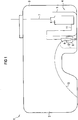
- Fig. 1 is a two chambers 2, 3 existing fuel tank 1 is shown.
- a delivery unit 4 consisting of a swirl pot 5 and a fuel pump 6 arranged therein, fixed. Via a feed line 7, the funded by the fuel pump 6 fuel is passed to an internal combustion engine, not shown.
- a pot 8 is attached on the outer wall of the swirl pot 5, a pot 8 is attached.
- a suction jet pump 9 is arranged to the pot 8, that the mixing tube 10 projects into the pot.
- fuel is supplied to the suction jet pump 9 from the fuel pump 6.
- a further line 12 extends from the suction jet pump 9 in the other chamber 2. Via the line 12 fuel is conveyed from the chamber 2 into the chamber 3 or directly into the swirl pot 5.
- the in the FIGS. 2a-c shown suction jet pump 9 consists of a propulsion jet nozzle 13, a mixing tube 14, the suction pipe 12 and a pot 8.
- a propellant jet 15 of the suction jet pump 9 is supplied.
- the propulsion jet 15 exits through the propulsion jet nozzle 13 and into the mixing tube 14.
- the intake line 12 opens into the suction jet pump 9.
- the suction jet pump 9 is arranged vertically with respect to the axial extent of the mixing tube 14. Farther the suction jet pump 9 is arranged to the pot 8, that the outlet opening 16 of the mixing tube 14 is immersed in the pot 8. In the in Fig. 2a shown state, the pot 8 is only slightly filled with fuel.
- the propulsion jet 15 passes from the propulsion jet nozzle 13 via the mixing tube 14 into the pot 8, whereby the propulsion jet 15 fills the pot 8.
- the generated negative pressure in the suction jet pump 9 is not sufficient to promote a larger amount of fuel from the chamber 2 via the suction line 12.
- suction jet pump 9 is connected to the pot 8 via a plug connection.
- a spring 17 is formed, while the inner wall of the pot 8 has a groove 18 at one point.
- the suction jet pump 9 is positioned to the pot 8.
- the suction jet pump 9 is arranged eccentrically to the pot 8. In this way, a preferred outflow direction of the fuel is generated from the pot 8, which, relative to the circumference of the pot 8, the suction jet pump 9 is opposite.
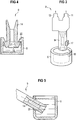
- Fig. 4 shows a further embodiment of the attachments of the suction jet pump 9 on the pot 8.
- latching elements in the form of latching hooks 21 are formed in the region of the outlet opening, which cooperate with correspondingly formed latching points 22 which are integrally formed on the pot 8. It is also conceivable to provide the latching hook 21 on the pot 8, while the mixing tube 14 have the necessary resting points 22.
- the suction jet pump 9 is arranged at an angle of 40 ° to the horizontal with respect to the axial extent of the mixing tube 14.
- the mixing tube 14 is set. Through the bore 23, the mixing tube 14 is held in position.
- the diameters of the mixing tube 14 and the bore 23 are formed as a press fit. As a result, the mixing tube 14 is reliably held in position.
- the bottom of the pot 8 forms the stop for the mixing tube 14 during assembly.
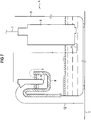
- the pot 8 is not a separate component, but part of the swirl pot 5 of the conveyor unit 4.
- a wall 24 is formed, which forms the pot 8 together with the wall 25 of the swirl pot 5.
- the mixing tube 14 protrudes with its outlet opening 16 into the pot 8.
- the subsidized by the ejector 9 fuel flows from the pot 8 directly into the swirl pot 5. From there, the fuel is conveyed from the fuel pump, not shown, to the engine.
- Fig. 7 shows a modified form of the arrangement of the ejector after Fig. 6
- the pot 8 is at the top of the Schwall pot 5 attached.
- the pot 8 can be arranged both inside and outside of the swirl pot 5.
- the suction jet pump 9 is secured in a suitable manner in the pot 8.
- the strength of the propellant conduit 11 is achieved by the material of the propellant conduit 11 or by reinforcing elements, for example wire insert.
Landscapes
- Engineering & Computer Science (AREA)
- Mechanical Engineering (AREA)
- General Engineering & Computer Science (AREA)
- Physics & Mathematics (AREA)
- Fluid Mechanics (AREA)
- Chemical & Material Sciences (AREA)
- Combustion & Propulsion (AREA)
- Jet Pumps And Other Pumps (AREA)
- Details Of Rigid Or Semi-Rigid Containers (AREA)
Abstract
Description
- Gegenstand der Erfindung ist eine Saugstrahlpumpe mit einer Treibstrahldüse, einem Mischrohr, einer Ansaugöffnung und einer daran angeschlossenen Ansaugleitung. Die Saugstrahlpumpe dient zum Fördern von Kraftstoff innerhalb eines Kraftstoffbehälters oder aus einem Kraftstoffbehälter in einem Schwalltopf, der innerhalb des Kraftstoffbehälters angeordnet ist.
- Es ist bekannt, dass Kraftstoffbehälter vielfältige Formen aufweisen. Mit der Anpassung des Kraftstoffbehälters an das Kraftfahrzeug unter Nutzung des vorhandenen Bautraumes entstehen Kraftstoffbehälter, die in mehreren Kammern unterteilt sind.
- Diese Kammern sind größtenteils mit einem Sattel verbunden. Bei derartigen Kraftstoffbehältern tritt das Problem auf, dass der Kraftstoff bei niedrigem Füllstand aus der einen Kammer nicht mehr über den Sattel in die andere Kammer gelangen kann. Da üblicherweise nur eine Fördereinheit in einem Kraftstoffbehälter angeordnet ist, kann der in einer anderen Kammer befindliche Kraftstoff die Fördereinheit nicht erreichen. In diesen Fällen werden Saugstrahlpumpen eingesetzt, um den in anderen Bereichen des Kraftstoffbehälters vorhandene Kraftstoff der Fördereinheit zuzuführen oder den Kraftstoff zumindest in die Kammer oder den Bereich, in dem sich die Fördereinheit befindet, zu fördern. Eine solche Saugstrahlpumpe ist z.B. aus der
DE 37 32 415 A1 bekannt, die alle Merkmale des Oberbegriffs des Anspruchs 1 offenbart. - Herkömmliche Saugstrahlpumpen werden am Boden der Kammern oder der Bereiche des Kraftstoffbehälters angeordnet, aus denen der Kraftstoff zur Fördereinheit gefördert werden soll.
- Mit der Anordnung der Ansaugöffnung der Saugstrahlpumpe am Boden des Kraftstoffbehälters befindet sich die Saugstrahlpumpe immer im Kraftstoff und ist somit immer betriebsbereit. Derartige Saugstrahlpumpen rechnen sich durch einen guten Wirkungsgrad aus. Der Förderfaktor, das heißt, das Verhältnis von Summenstrahl zu Treibstrahl, liegt mindestens bei 7. Nachteilig hierbei ist, dass mit der Treibmittelleitung zur Saugstrahlpumpe und der Summenleitung von der Saugstrahlpumpe zwei Leitungen erforderlich sind, die im Kraftstoffbehälter verlegt und befestigt werden müssen.
- Weiterhin ist bekannt, saugende Saugstrahlpumpen zu verwenden, die im Bereich der Fördereinheit angeordnet sind. Von der Saugstrahlpumpe führt eine Saugleitung in dem Bereich, aus dem der Kraftstoff gefördert werden soll. Zur Erzeugung des notwendigen Unterdrucks in der Saugleitung besitzt die Saugstrahlpumpe eine spezielle Treibstrahldüse. Die Austrittsöffnung der Treibstrahldüse ist als Schlitz ausgeführt. In Folge des Schlitzes wird der Treibstrahl nach dem Austreten aus der Treibstrahldüse aufgefächert. Der aufgefächerte Treibstrahl verschließt das Mischrohr, wodurch der notwendige Unterdruck erzeugt wird, um über die relativ lange Ansaugleitung den Kraftstoff ansaugen zu können. Dadurch ist nur eine statt wie bisher zwei im Kraftstoffbehälter zu verlegende und zu befestigende Leitungen notwendig. Nachteilig bei dieser Ausführungsform ist der niedrige Förderfaktor der saugenden Saugstrahlpumpe, der ungefähr bei 2 liegt. Dieser niedrige Förderfaktor ist bedingt durch das Auffächern des Treibstrahls nach dem Verlassen der Treibstrahldüse.
- Der vorliegenden Erfindung liegt daher die Aufgabe zugrunde, eine saugende Saugstrahlpumpe mit einem verbesserten Förderfaktor zu schaffen. Die Saugstrahlpumpe soll darüber hinaus einfach und kompakt aufgebaut und leicht zu montieren sein.
- Gelöst wird die Aufgabe mit den Merkmalen des Anspruchs 1. Vorteilhafte Ausgestaltungen sind in den Unteransprüchen enthalten.
- Die erfindungsgemäße Saugstrahlpumpe besteht aus einer Treibstrahldüse, einem Mischrohr und einer mit einer Ansaugleitung verbundenen Ansaugöffnung, wobei zumindest ein Teil des Mischrohres in einem Topf angeordnet ist. Aufgrund des im Topf befindlichen Fördermediums wird das Mischrohr gegen die Umgebung abgedichtet. Mit der Abdichtung des Mischrohres bildet sich in der Saugstrahlpumpe ein Unterdruck aus, der das Ansaugen des zu fördernden Mediums über eine weite Strecke ermöglicht. Der Vorteil der Erfindung besteht darin, dass mit der Ansaugleitung nur noch eine Leitung im Kraftstoffbehälter angeordnet ist und dass die Saugstrahlpumpe einen Förderfaktor wie herkömmliche Saugstrahlpumpen besitzt. Zudem ist die Saugstrahlpumpe in ihrer Anordnung infolge der hohen Saugwirkung nicht mehr auf den Bodenbereich des Kraftstoffbehälters oder des Schwalltopfes beschränkt.
- Die Saugstrahlpumpe ist vorteilhafterweise in Bezug auf ihrer axialen Erstreckung in einem von der horizontalen abweichenden Winkel angeordnet. Die Wahl des Winkels kann in Abhängigkeit von den vorhandenen Platzverhältnissen im Kraftstoffbehälter erfolgen. Als besonders günstig hat sich die senkrechte Anordnung der Saugstrahlpumpe erwiesen, bei der die Saugstrahlpumpe in Bezug auf ihrer axiale Erstreckung einen Winkel zur Horizontalen von 90° aufweist. Diese senkrechte Anordnung der Saugstrahlpumpe ist besonders platzsparend. Diese Lage ermöglicht die Anordnung der Saugstrahlpumpe am oder im Schwalltopf einer im Kraftstoffbehälter befindlichen Fördereinheit. Auf diese Weise kann eine separate Befestigung der Saugstrahlpumpe am Kraftstoffbehälter entfallen. Zudem kann die Saugstrahlpumpe mit der Fördereinheit vormontiert, getestet und anschließen in einem Arbeitsschritt in dem Kraftstoffbehälter angebracht werden.
- In vorteilhafter Ausgestaltung befindet sich lediglich die Auslassöffnung des Mischrohres im Topf. Dies ermöglicht eine sehr flache und damit relativ kleine Ausbildung des Topfes.
- Der Topf ist in einer weiteren Ausgestaltung mit der Saugstrahlpumpe verbunden. Der Topf kann einteilig mit der Saugstrahlpumpe, vorzugsweise am Mischrohr, angeformt sein. Die Fertigung der erfindungsgemäßen Saugstrahlpumpe gestaltet sich jedoch besonders einfach, wenn der Topf mittels einer Rast- oder Steckverbindung mit der Saugstrahlpumpe verbunden ist. Auf diese Weise bildet der Topf mit der Saugstrahlpumpe eine Einheit. Die Saugstrahlpumpe ist dadurch an beliebigen Orten einsetzbar.
- Die Verbindung von Topf und Saugstrahlpumpe gestaltet sich vorteilhaft, wenn sowohl an der Saugstrahlpumpe als auch am Topf Rast- oder Steckelemente, die ineinander greifen, vorhanden sind. Besonders einfach lassen sich der Topf und die Saugstrahlpumpe verbinden, wenn der Topf eine Nut aufweist, in die eine am Mischrohr angeformte Feder eingreift.
- Wird die Saugstrahlpumpe zur Befüllung des Schwalltopfes verwendet, kann die Saugstrahlpumpe über den oberen Rand in den Schwalltopf fördern, wobei sie vorteilhafterweise im Bereich des oberen Randes angeordnet ist. Die bisher vorgesehene Ansaugöffnungen im Boden des Schwalltopfes ist nicht mehr erforderlich. Damit entfällt ebenso das Ventil, welches die durch die Saugstrahlpumpe verursachte Öffnung verschließt, wenn die Saugstrahlpumpe nicht in Betrieb ist.
- Die erfindungsgemäße Vorrichtung gestaltet sich besonders einfach, wenn der Topf von einem anderen Bauteil gebildet oder in dieses Bauteil integriert ist. So kann der Topf am Schwalltopf angeordnet sein. Der Topf ist hierbei entweder an dem Schwalltopf angeformt oder er wird am Schwalltopf befestigt. Der hierbei verwendete Schwalltopf ist besonders einfach gestaltet, wenn ein Teil des Bodens abgeteilt ist, so dass diese abgeteilte Bereich den Topf bildet. Ebenso gut kann der Schwalltopf an seiner Außenwandung eine Anformung aufweisen, die den Topf für die Saugstrahlpumpe bildet. Der Vorteil dieser Ausgestaltungen besteht darin, dass lediglich die Saugstrahlpumpe montiert werden muß.
- An mehreren Ausführungsbeispielen wird die Erfindung näher erläutert. Dabei zeigen die Figuren in
- Fig. 1:
- eine Anordnung der Saugstrahlpumpe in einem Kraftstoffbehälter,
- Fig. 2 a - c:
- die Wirkungsweise der erfindungsgemäßen Saugstrahlpumpe,
- Fig. 3-5:
- verschiedene Anordnungen der Saugstrahlpumpe zum Topf und
- Fig. 6, 7:
- die Anordnung der Saugstrahlpumpe an einem Schwalltopf.
- In
Fig. 1 ist ein aus zwei Kammern 2, 3 bestehender Kraftstoffbehälter 1 dargestellt. In dem Kraftstoffbehälter 1 ist eine Fördereinheit 4, bestehend aus einem Schwalltopf 5 und einer darin angeordneten Kraftstoffpumpe 6, befestigt. Über eine Vorlaufleitung 7 wird der von der Kraftstoffpumpe 6 geförderte Kraftstoff zu einer nicht dargestellten Brennkraftmaschine geleitet. An der Außenwand des Schwalltopfes 5 ist ein Topf 8 befestigt. Eine Saugstrahlpumpe 9 ist derart zu dem Topf 8 angeordnet, dass deren Mischrohr 10 in dem Topf hineinragt. über eine Leitung 11 wird aus der Kraftstoffpumpe 6 Kraftstoff der Saugstrahlpumpe 9 zugeführt. Eine weitere Leitung 12 erstreckt sich von der Saugstrahlpumpe 9 in die andere Kammer 2. Über die Leitung 12 wird Kraftstoff aus der Kammer 2 in die Kammer 3 oder direkt in den Schwalltopf 5 gefördert. - Die in den
Figuren 2a - c dargestellte Saugstrahlpumpe 9 besteht aus einer Treibstrahldüse 13, einem Mischrohr 14, der Ansaugleitung 12 und einem Topf 8. Mittels der Treibstrahlleitung 11 wird ein Treibstrahl 15 der Saugstrahlpumpe 9 zugeführt. Der Treibstrahl 15 tritt durch die Treibstrahldüse 13 aus und in das Mischrohr 14 ein. Im Bereich der Treibstrahldüse 13 mündet die Ansaugleitung 12 in die Saugstrahlpumpe 9. Die Saugstrahlpumpe 9 ist bezüglich der axialen Erstreckung des Mischrohres 14 senkrecht angeordnet. Weiterhin ist die Saugstrahlpumpe 9 derart zu dem Topf 8 angeordnet, dass die Auslassöffnung 16 des Mischrohres 14 in den Topf 8 eintaucht. In dem inFig. 2a dargestellten Zustand ist der Topf 8 nur gering mit Kraftstoff gefüllt. Der Treibstrahl 15 gelangt aus der Treibstrahldüse 13 über das Mischrohr 14 in den Topf 8, wodurch der Treibstrahl 15 den Topf 8 befüllt. Der dabei erzeugte Unterdruck in der Saugstrahlpumpe 9 ist dabei nicht ausreichend, um eine größere Menge Kraftstoff aus der Kammer 2 über die Ansaugleitung 12 zu fördern. - Aufgrund des Treibstrahls 15 und des geringen Topfvolumens wird der Topf 8 unmittelbar nach dem Betriebsbeginn der Saugstrahlpumpe 9 gefüllt. Mit dem steigenden Füllstand im Topf 8 wird die Auslassöffnung 16 des Mischrohres 14 geflutet, so dass es zu einem Flüssigkeitsverschluss im Mischrohr 14 und damit in der Saugstrahlpumpe 9 kommt. Diese Situation ist in
Fig. 2b dargestellt. Aufgrund des nunmehr vollständigen Verschlusses des Mischrohres 14 erzeugt der Treibstrahl 15 einen wesentlich größeren Unterdruck, der wiederum ausreichend ist, um eine größere Menge an Kraftstoff über eine relativ große Entfernung mittels der Ansaugleitung 12 in den Topf 8 gemäßFig. 2c zu fördern. - Die in
Fig. 3 gezeigte Saugstrahlpumpe 9 ist mit dem Topf 8 über eine Steckverbindung verbunden. An der Außenseite des Mischrohres 14 ist eine Feder 17 angeformt, während die Innenwandung des Topfes 8 an einer Stelle eine Nut 18 aufweist. Zum Verbinden von Topf 8 und Saugstrahlpumpe 9 wird die Feder 17 in die Nut 18 eingeschoben. Mit Erreichen der unteren Nutbegrenzung ist die Saugstrahlpumpe 9 zum Topf 8 positioniert. Die Saugstrahlpumpe 9 ist dabei exzentrisch zum Topf 8 angeordnet. Auf diese Weise wird eine bevorzugte Ausflussrichtung des Kraftstoffes aus dem Topf 8 erzeugt, die, auf den Umfang des Topfes 8 bezogen, der Saugstrahlpumpe 9 gegenüberliegt. Durch eine vonFig. 3 abweichende Ausgestaltung des Nutgrundes 19 in der Art, dass der Nutgrund nunmehr gegenüber der Horizontalen einen kleineren Winkel als 90° aufweist, läßt sich die Saugstrahlpumpe 9 in Bezug auf die axiale Ausdehnung des Mischrohres 14 in einem von der vertikalen abweichenden Winkel anordnen. -
Fig. 4 zeigt eine weitere Ausgestaltung für die Befestigungen der Saugstrahlpumpe 9 am Topf 8. Am Mischrohr 14 sind im Bereich der Auslassöffnung 16 Rastelemente in Form von Rasthaken 21 angeformt, die mit entsprechend ausgebildeten Raststellen 22, die am Topf 8 angeformt sind, zusammenwirken. Es ist auch denkbar, die Rasthaken 21 am Topf 8 vorzusehen, während das Mischrohr 14 die notwendigen Raststellen 22 besitzen. - In der Darstellung nach
Fig. 5 ist die Saugstrahlpumpe 9 in einem Winkel von 40° zur Horizontalen in Bezug auf die axiale Erstreckung des Mischrohres 14 angeordnet. Über eine im Topf 8 vorhandene Bohrung 23 ist das Mischrohr 14 eingestellt. Durch die Bohrung 23 wird das Mischrohr 14 in seiner Lage gehalten. Die Durchmesser des Mischrohres 14 und der Bohrung 23 sind als Presspassung ausgebildet. Dadurch wird das Mischrohr 14 zuverlässig in seiner Lage gehalten. Der Boden des Topfes 8 bildet bei der Montage den Anschlag für das Mischrohr 14. - In der in
Fig. 6 gezeigten Ausgestaltung ist der Topf 8 kein separates Bauteil, sondern Bestandteil des Schwalltopfes 5 der Fördereinheit 4. Am Boden 23 des Schwalltopfes 5 ist eine Wand 24 angeformt, die zusammen mit der Wandung 25 des Schwalltopfes 5 den Topf 8 bildet. Das Mischrohr 14 ragt mit seiner Auslassöffnung 16 in den Topf 8 hinein. Der von der Saugstrahlpumpe 9 geförderte Kraftstoff strömt aus dem Topf 8 direkt in den Schwalltopf 5. Von dort wird der Kraftstoff von der nicht dargestellten Kraftstoffpumpe zur Brennkraftmaschine gefördert. -
Fig. 7 zeigt eine abgewandelte Form der Anordnung der Saugstrahlpumpe nachFig. 6 . Der Topf 8 ist am oberen Rand des Schwalltopfes 5 befestigt. Der Topf 8 kann dabei sowohl innerhalb als auch außerhalb des Schwalltopfes 5 angeordnet sein. Die Saugstrahlpumpe 9 ist in geeigneter Weise im Topf 8 befestigt. Es ist aber auch denkbar, die Treibmittelleitungen 11 mit einer derartigen Festigkeit auszubilden, dass die Saugstrahlpumpe 9 durch die Treibmittelleitung 11 im Topf 8 gehalten wird. Die Festigkeit der Treibmittelleitung 11 wird durch das Material der Treibmittelleitung 11 oder durch Verstärkungselemente, zum Beispiel Drahteinlage, erreicht.
Claims (10)
- Saugstrahlpumpe, bestehend aus einer Treibstrahldüse (13) mit einer runden Düsenöffnung, einem Mischrohr (14), einer Ansaugöffnung und einer daran angeordneten Saugleitung, dadurch gekennzeichnet, dass zumindest ein Teil des Mischrohres (14) in einem Topf (8) angeordnet ist, der an einem Schwalltopf (5) angeordnet ist.
- Saugstrahlpumpe nach Anspruch 1, dadurch gekennzeichnet, dass die Auslassöffnung 16 des Mischrohres (14) innerhalb des Topfes (8) angeordnet ist.
- Saugstrahlpumpe nach Anspruch 1 und 2, dadurch gekennzeichnet, dass das Mischrohr (14) in Bezug auf seiner axialen Erstreckung in einem von der horizontalen abweichenden Winkel angeordnet ist.
- Saugstrahlpumpe nach Anspruch 3, dadurch gekennzeichnet, dass das Mischrohr (14) in Bezug auf seiner axialen Erstreckung senkrecht angeordnet ist.
- Saugstrahlpumpe nach Anspruch 3, dadurch gekennzeichnet, dass das Mischrohr (14) in Bezug auf seiner axiale Erstreckung in einem Winkel zwischen 5° und 85°, vorzugsweise zwischen 20° und 70° angeordnet ist.
- Saugstrahlpumpe nach zumindest einem der vorhergehenden Ansprüche, dadurch gekennzeichnet, dass der Topf (8) mit der Saugstrahlpumpe (9) verbunden ist.
- Saugstrahlpumpe nach Anspruch 6, dadurch gekennzeichnet, dass der Topf (8) mit der Saugstrahlpumpe (9) mittels einer Rast- oder Steckverbindung verbunden ist.
- Saugstrahlpumpe nach Anspruch 6, dadurch gekennzeichnet, dass der Topf (8) an der Saugstrahlpumpe (9) angeformt ist.
- Saugstrahlpumpe nach Anspruch 8, dadurch gekennzeichnet, dass der Topf (8) mit der Saugstrahlpumpe (9) verschweißt oder verklebt ist.
- Saugstrahlpumpe nach zumindest einem der vorhergehenden Ansprüche, dadurch gekennzeichnet, dass der Topf (8) an dem Schwalltopf (5) oder in einem Bereich des Schwalltopfes (5) ausgebildet ist.
Applications Claiming Priority (3)
| Application Number | Priority Date | Filing Date | Title |
|---|---|---|---|
| DE2002137050 DE10237050B3 (de) | 2002-08-09 | 2002-08-09 | Saugstrahlpumpe |
| DE10237050 | 2002-08-09 | ||
| PCT/DE2003/002166 WO2004018864A1 (de) | 2002-08-09 | 2003-06-30 | Saugstrahlpumpe |
Publications (2)
| Publication Number | Publication Date |
|---|---|
| EP1527269A1 EP1527269A1 (de) | 2005-05-04 |
| EP1527269B1 true EP1527269B1 (de) | 2012-04-25 |
Family
ID=31895547
Family Applications (1)
| Application Number | Title | Priority Date | Filing Date |
|---|---|---|---|
| EP20030792114 Expired - Lifetime EP1527269B1 (de) | 2002-08-09 | 2003-06-30 | Saugstrahlpumpe |
Country Status (8)
| Country | Link |
|---|---|
| US (1) | US7874811B2 (de) |
| EP (1) | EP1527269B1 (de) |
| JP (1) | JP2005535830A (de) |
| KR (1) | KR20050040916A (de) |
| CN (1) | CN100467852C (de) |
| BR (1) | BR0313472A (de) |
| DE (1) | DE10237050B3 (de) |
| WO (1) | WO2004018864A1 (de) |
Families Citing this family (15)
| Publication number | Priority date | Publication date | Assignee | Title |
|---|---|---|---|---|
| HUP0400276A2 (hu) * | 2004-01-27 | 2005-10-28 | Visteon Global Technologies, Inc. | Javított indítási tulajdonságokkal rendelkező sugárszivattyú, valamint ilyennel szerelt üzemanyag-továbbító rendszer |
| DE102005014287B4 (de) * | 2005-03-24 | 2007-01-25 | Siemens Ag | Fördereinheit |
| DE102005014431B3 (de) * | 2005-03-24 | 2006-08-03 | Siemens Ag | Saugstrahlpumpe |
| DE102005018469A1 (de) * | 2005-04-21 | 2006-11-02 | Robert Bosch Gmbh | Vorrichtung zum Fördern von Kraftstoff aus einem Kraftstofftank zur Brennkraftmaschine eines Kraftfahrzeuges |
| FR2890341B1 (fr) * | 2005-09-02 | 2008-10-24 | Inergy Automotive Systems Res | Systeme a carburant comprenant une reserve a carburant et un bac de retention |
| DE102005047468B3 (de) * | 2005-09-30 | 2007-06-14 | Siemens Ag | Ansaugeinheit |
| DE102006024456A1 (de) * | 2006-05-24 | 2007-11-29 | Siemens Ag | Saugstrahlpumpe |
| JP4821678B2 (ja) * | 2007-03-30 | 2011-11-24 | 株式会社デンソー | ポンプユニット |
| JP4715793B2 (ja) * | 2007-03-30 | 2011-07-06 | 株式会社デンソー | ポンプユニット |
| US7913670B2 (en) * | 2007-06-18 | 2011-03-29 | Continental Automotive Systems Us, Inc. | Venturi jet structure for fuel delivery module of a fuel tank |
| DE102009049799B4 (de) * | 2009-10-16 | 2018-07-12 | Kautex Textron Gmbh & Co. Kg | Kraftstoffbehälter für ein KFZ |
| DE102011084682A1 (de) * | 2011-10-18 | 2013-04-18 | Robert Bosch Gmbh | Kraftstoffförder-Vorrichtung mit geneigter Saugstrahlpumpe |
| CN103016223B (zh) * | 2012-12-06 | 2016-03-30 | 联合汽车电子有限公司 | 副油泵支架总成 |
| DE102016217800B4 (de) * | 2016-09-16 | 2021-12-23 | Vitesco Technologies GmbH | Fluidfördervorrichtung |
| DE112019005806B4 (de) * | 2018-11-20 | 2024-01-25 | Walbro Llc | Kraftstoffpumpenanordnung mit elektrischer Motorkraftstoffpumpe und fluidgetriebener Kraftstoffpumpe |
Family Cites Families (45)
| Publication number | Priority date | Publication date | Assignee | Title |
|---|---|---|---|---|
| JPS6268129A (ja) * | 1985-09-18 | 1987-03-28 | Nissan Motor Co Ltd | 燃料タンクの燃料吸込装置 |
| DE3602135C1 (de) * | 1986-01-24 | 1992-07-02 | Bayerische Motoren Werke Ag | Lagerung einer Kraftstoffpumpe im Kraftstoffvorratsbehaelter eines Kraftfahrzeuges |
| JPH0737783B2 (ja) * | 1986-02-17 | 1995-04-26 | 日本電装株式会社 | 燃料供給装置 |
| US4834132A (en) * | 1986-09-25 | 1989-05-30 | Nissan Motor Company, Limited | Fuel transfer apparatus |
| JP2598091B2 (ja) * | 1988-07-15 | 1997-04-09 | 日産自動車株式会社 | 燃料タンクの燃料吸込装置 |
| JPH0745856B2 (ja) * | 1988-12-23 | 1995-05-17 | 日産自動車株式会社 | 燃料タンクの燃料吸込装置 |
| JP2596150B2 (ja) * | 1989-12-13 | 1997-04-02 | 日産自動車株式会社 | 車両用燃料タンクのエゼクタポンプ |
| JP2961994B2 (ja) * | 1991-10-08 | 1999-10-12 | 株式会社デンソー | 燃料供給装置 |
| US5139000A (en) * | 1991-10-28 | 1992-08-18 | General Motors Corporation | Automotive fuel system |
| DE4219516A1 (de) * | 1992-06-13 | 1993-12-16 | Bosch Gmbh Robert | Kraftstofftank mit einem in diesem angeordneten Behälter |
| DE4224981C2 (de) * | 1992-07-29 | 2003-06-26 | Bosch Gmbh Robert | Einrichtung zum Fördern von Kraftstoff aus einem Vorratstank zur Brennkraftmaschine eines Kraftfahrzeuges |
| US5218942A (en) * | 1992-11-30 | 1993-06-15 | General Motors Corporation | Modular fuel sender for motor vehicle |
| DE4242242C2 (de) * | 1992-12-15 | 2003-04-30 | Bosch Gmbh Robert | Vorrichtung zum Versorgen der Brennkraftmaschine eines Kraftfahrzeuges mit in einem Vorratstank vorhandenem Kraftstoff |
| DE4328198C2 (de) * | 1993-08-21 | 2001-09-06 | Mannesmann Vdo Ag | In einen Kraftstoffbehälter einzusetzende Kraftstoff-Entnahmeeinrichtung |
| DE4426685B4 (de) * | 1993-08-25 | 2004-03-11 | Volkswagen Ag | Kraftstoffversorgung für eine Brennkraftmaschine mit einem zumindest zwei Teilbehälter bildenden Kraftstoffbehälter |
| DE4336060C2 (de) | 1993-10-22 | 2003-06-26 | Siemens Ag | Kraftstoff-Fördereinrichtung für eine Brennkraftmaschine |
| DE4343199A1 (de) * | 1993-12-17 | 1995-06-22 | Vdo Schindling | Saugstrahlpumpeneinheit |
| US5402558A (en) * | 1994-05-09 | 1995-04-04 | Selfix, Inc. | Resilient clip |
| US5732684A (en) * | 1994-09-22 | 1998-03-31 | Ford Global Technologies, Inc. | Automotive fuel delivery system with pressure actuated auxiliary fuel pump |
| DE19504217C2 (de) * | 1995-02-09 | 2002-11-14 | Bosch Gmbh Robert | Vorrichtung zum Fördern von Kraftstoff aus einem Vorratstank zur Brennkraftmaschine eines Kraftfahrzeuges |
| DE19618649A1 (de) * | 1996-05-09 | 1997-11-13 | Bosch Gmbh Robert | Kraftstoffördereinrichtung eines Kraftfahrzeuges |
| FR2753658B1 (fr) * | 1996-09-26 | 1998-12-11 | Dispositif de puisage de carburant pour reservoir de vehicules automobiles | |
| DE19750036C2 (de) * | 1997-11-12 | 1999-09-02 | Mannesmann Vdo Ag | Kraftstoffördereinrichtung |
| DE19816317A1 (de) * | 1998-04-11 | 1999-10-14 | Bosch Gmbh Robert | Kraftstoffördereinrichtung |
| FR2779184B1 (fr) | 1998-05-26 | 2001-01-26 | Marwal Systems | Ensemble de puisage de carburant dans un reservoir de vehicule automobile |
| DE19833130A1 (de) * | 1998-07-23 | 2000-01-27 | Bosch Gmbh Robert | Vorrichtung zum Fördern von Kraftstoff aus einem Vorratsbehälter zur Brennkraftmaschine eines Kraftfahrzeugs |
| EP0979939B1 (de) * | 1998-08-10 | 2006-10-04 | Siemens Aktiengesellschaft | Kraftstoffversorgungsanlage |
| DE19855433B4 (de) * | 1998-11-27 | 2005-10-06 | Siemens Ag | Saugstrahlpumpe |
| FR2798164B1 (fr) * | 1999-09-07 | 2001-11-23 | Marwal Systems | Dispositif de puisage de carburant pour reservoir de vehicule automobile |
| DE19957066A1 (de) | 1999-11-26 | 2001-05-31 | Mannesmann Vdo Ag | Saugstrahlpumpe |
| US6283142B1 (en) * | 2000-02-04 | 2001-09-04 | Robert Bosch Corporation | Dual fuel delivery module system for bifurcated automotive fuel tanks |
| JP3884212B2 (ja) * | 2000-03-24 | 2007-02-21 | 株式会社日立製作所 | 燃料供給装置 |
| DE10027650A1 (de) * | 2000-06-03 | 2002-08-29 | Siemens Ag | Kraftstoffördereinheit |
| US6505644B2 (en) * | 2000-06-09 | 2003-01-14 | Delphi Technologies, Inc. | Dual barrel jet fuel pump assembly for a fuel tank |
| DE10055355C2 (de) * | 2000-11-08 | 2003-07-10 | Kautex Textron Gmbh & Co Kg | Kraftstofftank |
| JP2002221111A (ja) * | 2001-01-24 | 2002-08-09 | Calsonic Kansei Corp | 燃料供給装置 |
| US6371153B1 (en) * | 2001-03-16 | 2002-04-16 | Robert Bosch Corporation | Dual fuel delivery module system for multi-chambered or multiple automotive fuel tanks |
| JP4370610B2 (ja) * | 2001-06-29 | 2009-11-25 | 株式会社デンソー | 燃料供給装置 |
| DE10143819B4 (de) * | 2001-09-06 | 2005-12-01 | Siemens Ag | Kraftstoffmodul |
| DE10161403B4 (de) * | 2001-12-13 | 2007-03-29 | Siemens Ag | Kraftstofffördereinheit |
| JP2003293875A (ja) * | 2002-04-03 | 2003-10-15 | Aisan Ind Co Ltd | リザーブ容器ユニット |
| US6705298B2 (en) * | 2002-05-20 | 2004-03-16 | Denso International America, Inc. | Fuel pump module |
| DE10229801A1 (de) * | 2002-07-03 | 2004-01-22 | Ti Automotive (Neuss) Gmbh | Saugstrahlpumpe |
| JP4051564B2 (ja) * | 2002-10-18 | 2008-02-27 | 株式会社デンソー | 燃料供給装置 |
| US6907899B2 (en) * | 2003-01-22 | 2005-06-21 | Visteon Global Technologies, Inc. | Saddle tank fuel delivery system |
-
2002
- 2002-08-09 DE DE2002137050 patent/DE10237050B3/de not_active Expired - Fee Related
-
2003
- 2003-06-30 WO PCT/DE2003/002166 patent/WO2004018864A1/de not_active Ceased
- 2003-06-30 BR BR0313472A patent/BR0313472A/pt not_active Application Discontinuation
- 2003-06-30 EP EP20030792114 patent/EP1527269B1/de not_active Expired - Lifetime
- 2003-06-30 JP JP2004529696A patent/JP2005535830A/ja active Pending
- 2003-06-30 US US10/523,752 patent/US7874811B2/en active Active
- 2003-06-30 CN CNB038192217A patent/CN100467852C/zh not_active Expired - Fee Related
- 2003-06-30 KR KR1020057002177A patent/KR20050040916A/ko not_active Ceased
Also Published As
| Publication number | Publication date |
|---|---|
| US20050241621A1 (en) | 2005-11-03 |
| WO2004018864A1 (de) | 2004-03-04 |
| DE10237050B3 (de) | 2004-04-15 |
| CN1675462A (zh) | 2005-09-28 |
| CN100467852C (zh) | 2009-03-11 |
| EP1527269A1 (de) | 2005-05-04 |
| BR0313472A (pt) | 2005-06-21 |
| JP2005535830A (ja) | 2005-11-24 |
| US7874811B2 (en) | 2011-01-25 |
| KR20050040916A (ko) | 2005-05-03 |
Similar Documents
| Publication | Publication Date | Title |
|---|---|---|
| EP1527269B1 (de) | Saugstrahlpumpe | |
| EP0694691B1 (de) | Vorrichtung zum Fördern von Kraftstoff aus einem Vorratsbehälter zur Brennkraftmaschine eines Kraftfahrzeugs | |
| DE3631639C2 (de) | Kraftstofftankanordnung | |
| EP1208017B1 (de) | Vorrichtung zum fördern von kraftstoff aus einem vorratstank zu einer brennkraftmaschine eines kraftfahrzeugs | |
| EP1037759B1 (de) | Vorrichtung zum fördern von kraftstoff aus einem vorratsbehälter zur brennkraftmaschine eines kraftfahrzeugs | |
| EP1301367A1 (de) | Kraftstoffördereinheit | |
| EP0806318A2 (de) | Kraftstoffördereinrichtung eines Kraftfahrzeuges | |
| DE3006254C2 (de) | Kraftstoffbehälter aus Kunststoff | |
| EP1004777B1 (de) | Saugstrahlpumpe | |
| DE19504217C2 (de) | Vorrichtung zum Fördern von Kraftstoff aus einem Vorratstank zur Brennkraftmaschine eines Kraftfahrzeuges | |
| DE102005029007B4 (de) | Tankeinbau-Kraftstoffversorgungseinheit mit montierbarer Strahlpumpeneinheit | |
| DE2401728A1 (de) | Im kraftstofftank eines kraftfahrzeuges angeordneter runder beruhigungstopf | |
| EP1492683B1 (de) | Kraftstofffördereinheit für ein kraftfahrzeug | |
| DE112007002074T5 (de) | Einstückige Doppelstrahlpumpe und diese verwendendes Kraftstoffsystem | |
| EP1861625B1 (de) | Saugstrahlpumpe | |
| DE102006016515A1 (de) | Saugstrahlpumpe | |
| DE19843318C5 (de) | Kraftstofffördereinheit | |
| EP0772745B1 (de) | Kraftstoffördereinrichtung mit einer saugstrahlpumpe | |
| EP1861612B1 (de) | Fördereinheit | |
| DE19725939A1 (de) | Förderaggregat | |
| EP2769076A1 (de) | Kraftstoffförder-vorrichtung mit geneigter saugstrahlpumpe | |
| EP1719658B1 (de) | In einem Kraftstoffbehälter angeordnete Fördereinheit | |
| DE9104511U1 (de) | Vorrichtung zum Fördern von Kraftstoff aus einem Vorratstank zur Brennkraftmaschine eines Kraftfahrzeugs |
Legal Events
| Date | Code | Title | Description |
|---|---|---|---|
| PUAI | Public reference made under article 153(3) epc to a published international application that has entered the european phase |
Free format text: ORIGINAL CODE: 0009012 |
|
| 17P | Request for examination filed |
Effective date: 20050107 |
|
| AK | Designated contracting states |
Kind code of ref document: A1 Designated state(s): AT BE BG CH CY CZ DE DK EE ES FI FR GB GR HU IE IT LI LU MC NL PT RO SE SI SK TR |
|
| RBV | Designated contracting states (corrected) |
Designated state(s): DE FR GB IT |
|
| RIN1 | Information on inventor provided before grant (corrected) |
Inventor name: TEICHERT, MICHAEL Inventor name: KIENINGER, KLEMENS |
|
| RAP1 | Party data changed (applicant data changed or rights of an application transferred) |
Owner name: CONTINENTAL AUTOMOTIVE GMBH |
|
| 17Q | First examination report despatched |
Effective date: 20091117 |
|
| REG | Reference to a national code |
Ref country code: DE Ref legal event code: R079 Ref document number: 50314318 Country of ref document: DE Free format text: PREVIOUS MAIN CLASS: F02M0037020000 Ipc: F02M0037100000 |
|
| GRAP | Despatch of communication of intention to grant a patent |
Free format text: ORIGINAL CODE: EPIDOSNIGR1 |
|
| RIC1 | Information provided on ipc code assigned before grant |
Ipc: F04F 5/54 20060101ALI20110909BHEP Ipc: F04F 5/10 20060101ALI20110909BHEP Ipc: F02M 37/10 20060101AFI20110909BHEP Ipc: F04F 5/44 20060101ALI20110909BHEP Ipc: F02M 37/02 20060101ALI20110909BHEP |
|
| GRAS | Grant fee paid |
Free format text: ORIGINAL CODE: EPIDOSNIGR3 |
|
| GRAA | (expected) grant |
Free format text: ORIGINAL CODE: 0009210 |
|
| AK | Designated contracting states |
Kind code of ref document: B1 Designated state(s): DE FR GB IT |
|
| REG | Reference to a national code |
Ref country code: GB Ref legal event code: FG4D Free format text: NOT ENGLISH |
|
| REG | Reference to a national code |
Ref country code: DE Ref legal event code: R096 Ref document number: 50314318 Country of ref document: DE Effective date: 20120621 |
|
| PLBE | No opposition filed within time limit |
Free format text: ORIGINAL CODE: 0009261 |
|
| STAA | Information on the status of an ep patent application or granted ep patent |
Free format text: STATUS: NO OPPOSITION FILED WITHIN TIME LIMIT |
|
| GBPC | Gb: european patent ceased through non-payment of renewal fee |
Effective date: 20120725 |
|
| 26N | No opposition filed |
Effective date: 20130128 |
|
| PG25 | Lapsed in a contracting state [announced via postgrant information from national office to epo] |
Ref country code: GB Free format text: LAPSE BECAUSE OF NON-PAYMENT OF DUE FEES Effective date: 20120725 |
|
| REG | Reference to a national code |
Ref country code: DE Ref legal event code: R097 Ref document number: 50314318 Country of ref document: DE Effective date: 20130128 |
|
| REG | Reference to a national code |
Ref country code: FR Ref legal event code: PLFP Year of fee payment: 14 |
|
| REG | Reference to a national code |
Ref country code: FR Ref legal event code: PLFP Year of fee payment: 15 |
|
| REG | Reference to a national code |
Ref country code: FR Ref legal event code: PLFP Year of fee payment: 16 |
|
| PGFP | Annual fee paid to national office [announced via postgrant information from national office to epo] |
Ref country code: IT Payment date: 20190624 Year of fee payment: 17 |
|
| REG | Reference to a national code |
Ref country code: DE Ref legal event code: R084 Ref document number: 50314318 Country of ref document: DE |
|
| REG | Reference to a national code |
Ref country code: DE Ref legal event code: R081 Ref document number: 50314318 Country of ref document: DE Owner name: VITESCO TECHNOLOGIES GMBH, DE Free format text: FORMER OWNER: CONTINENTAL AUTOMOTIVE GMBH, 30165 HANNOVER, DE |
|
| PGFP | Annual fee paid to national office [announced via postgrant information from national office to epo] |
Ref country code: FR Payment date: 20200619 Year of fee payment: 18 |
|
| PGFP | Annual fee paid to national office [announced via postgrant information from national office to epo] |
Ref country code: DE Payment date: 20210630 Year of fee payment: 19 |
|
| PG25 | Lapsed in a contracting state [announced via postgrant information from national office to epo] |
Ref country code: IT Free format text: LAPSE BECAUSE OF NON-PAYMENT OF DUE FEES Effective date: 20200630 |
|
| REG | Reference to a national code |
Ref country code: DE Ref legal event code: R081 Ref document number: 50314318 Country of ref document: DE Owner name: VITESCO TECHNOLOGIES GMBH, DE Free format text: FORMER OWNER: VITESCO TECHNOLOGIES GMBH, 30165 HANNOVER, DE |
|
| PG25 | Lapsed in a contracting state [announced via postgrant information from national office to epo] |
Ref country code: FR Free format text: LAPSE BECAUSE OF NON-PAYMENT OF DUE FEES Effective date: 20210630 |
|
| REG | Reference to a national code |
Ref country code: DE Ref legal event code: R119 Ref document number: 50314318 Country of ref document: DE |
|
| PG25 | Lapsed in a contracting state [announced via postgrant information from national office to epo] |
Ref country code: DE Free format text: LAPSE BECAUSE OF NON-PAYMENT OF DUE FEES Effective date: 20230103 |