EP1711285B1 - Verfahren und werkzeug zum biegen von stangenmaterial - Google Patents
Verfahren und werkzeug zum biegen von stangenmaterial Download PDFInfo
- Publication number
- EP1711285B1 EP1711285B1 EP04803056A EP04803056A EP1711285B1 EP 1711285 B1 EP1711285 B1 EP 1711285B1 EP 04803056 A EP04803056 A EP 04803056A EP 04803056 A EP04803056 A EP 04803056A EP 1711285 B1 EP1711285 B1 EP 1711285B1
- Authority
- EP
- European Patent Office
- Prior art keywords
- bending
- clamping
- core
- bar
- tool
- Prior art date
- Legal status (The legal status is an assumption and is not a legal conclusion. Google has not performed a legal analysis and makes no representation as to the accuracy of the status listed.)
- Not-in-force
Links
Images


Classifications
-
- B—PERFORMING OPERATIONS; TRANSPORTING
- B21—MECHANICAL METAL-WORKING WITHOUT ESSENTIALLY REMOVING MATERIAL; PUNCHING METAL
- B21D—WORKING OR PROCESSING OF SHEET METAL OR METAL TUBES, RODS OR PROFILES WITHOUT ESSENTIALLY REMOVING MATERIAL; PUNCHING METAL
- B21D11/00—Bending not restricted to forms of material mentioned in only one of groups B21D5/00, B21D7/00, B21D9/00; Bending not provided for in groups B21D5/00 - B21D9/00; Twisting
- B21D11/10—Bending specially adapted to produce specific articles, e.g. leaf springs
- B21D11/12—Bending specially adapted to produce specific articles, e.g. leaf springs the articles being reinforcements for concrete
Definitions
- the invention concerns a method for bending bar material, where bar material is fed to a bending tool by means of feeding means, is fixed by a clamping means during a bending operation and is bent to elements by means of a bending tool consisting of a bending core with a central bar channel and a bolt mounted on a bending disc and spaced apart from the centre thereof, where a bending roller is rotatably journalled on the bolt.
- the bar material may e.g. be rods for reinforcing concrete.
- the invention furthermore concerns a bending tool for performing the method, the tool including a rotatable bending disc and a bending core provided at the centre thereof and mounted with a central bar channel, where the bending core can be held non-rotatable at a given position, where at the bending disc a bending roller, which is rotatably journalled on a bolt, may rotate.
- a bending tool with a rotatable bending disc that has non-rotatable bending core at its centre. Spaced apart from the centre of the bending core, the bending disc carries a bolt with a bending roller rotatably journalled thereon and which may be pivoted by the rotatable bending disc about its centre for performing a predefined bending operation for bending elements in the form of one or more rods.
- the rods may be held fixed during the bending operation by clamping jaws provided outside the bending disc.
- a drawback of the said prior art is that after the last of a number of bending operations where a rod or a bundle of rods have been bent, the bent elements will still be fixed between the clamping jaws via rod material situated in the clamping jaws and between the bending core and the clamping jaws. This rod material is to be cut off after finishing the bending operation and thereby represents a considerable waste of material of 2.5 - 5% of the source material.
- the bending tool according to the invention is characterised in that at least one clamping means is mounted in the bending core for clamping the bar material to be bent in the bending tool.
- the method according to the invention may in a preferred embodiment be peculiar in that the clamping operation occurs by means of one or more clamping means.
- the part of the bar situated behind the feeding clamping jaw holding the bar for bending is too short to form yet a bent element.
- the part of the bar situated before the clamping jaw as well as the part of the bar located in the clamping jaw and between the clamping jaw and the bending core where the bar is to be cut off are wasted.
- the length of the bar available for bending an element is increased with the length of the part of the rod which by the prior art bending apparatus was situated between the clamping jaw and the bending core. In a certain number of cases, this increased length of the remaining part of the rod will be sufficient for bending yet an element. A corresponding saving of material is hereby attained.
- the bending tool according to the invention may in a preferred embodiment be peculiar in that at one side of the bar channel and upstream of the clamping means there is disposed a sharp edge part extending perpendicularly to the bottom of the bar channel, preferably of hardened steel, for interacting with the clamping means located at the opposite side of the channel.
- the bending tool according to the invention may in a further embodiment be peculiar in that at least one clamping means is constituted by a central pivot bolt that has a groove or slot which may be aligned with the bar channel of the bending core.
- at least one clamping means is constituted by a central pivot bolt that has a groove or slot which may be aligned with the bar channel of the bending core.
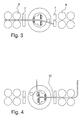
- Fig. 1 appears an example of a prior art design of a bending tool. It consists of a bending disc 1 which is rotatable about its centre and in the open centre of which a non-rotatable bending core 2 is provided, consisting of two opposed halves with an intermediate bar channel. The bending core 2 may be elevated and lowered between a position over and a position below the bending disc 1. A bolt is fastened to the bending disc 1 and is carrying a bending roller 3 which is rotatable about the bolt.
- Fig. 2 appears a bending tool with a bar channel in which is laid a rod 4 which by means of the bending roller 3 on the bolt is bent about the contour 5 of the bending core. Due to the turning movement of the bending disc 1, the rod 4 will tend to be pulled out from the core in the direction of arrow 6.
- clamping jaws 7 are disposed in front of and after the bending disc 1, and Fig. 3 shows such a disposition.
- the clamping jaws 7 are actuated while the bending takes place and holds the rod under this operation.
- the rod is advanced by means of drive roller mechanisms 8 or 9.
- the clamping jaws 7 and the drive roller mechanisms 8 and 9 may be depressed for avoiding collision with the bent ends of the rod.
- Some of the geometric conditions for the rods to be bent are given by the distances between respective drive roller mechanisms 8 and 9 and clamping jaws 7.
- the drive roller mechanism 9 and the clamping jaw 7 at the right side may be countersunk for avoiding collision with the bent part of the rod.
- the bending core may be turned 180°, and the drive roller mechanism in the left side may be countersunk.
- the section 10, which is situated between the bending core and the clamping jaw and in the clamping jaw itself, is to present a certain minimum length in order that the clamping jaw is to hold the rod during the bending operation.
- Systems in which the clamping jaw function is provided by the drive roller mechanism 8 and 9 are also known. The geometric limitation is the same.
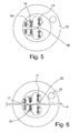
- a clamping jaw in the form of a squeezing piston 14 in the bending core 11 as an example of a tool according to the invention.
- the bar material to be bent is to be clamped after feeding in the bar channel 18 for receiving the rod 4 in the bending core 11.
- the bending core 11 is secured against turning and is provided at the centre of a bending disc 12.
- the bending disc 12 may rotate about the bending core 11.
- the clamping is effected by means of a steel hardened pressure member 13 which is pressed against the rod by a clamping piston 14 or 15.
- the bending disc 12 can turn about the bending core 11. Operation of the clamping piston 14 may occur hydraulically, pneumatically or mechanically or in combination thereof.
- clamping elements 13, 14 and 13, 15 may, due to the present limited space in the bending core itself, only exert a limited squeezing force.
- a second embodiment of the invention provides a special procedure for the clamping function and a special shape of the bending core.
- Fig. 6 shows this situation.
- one pressing member is pressed by its clamping piston 15 against the side of the rod 4 opposite the bolt with its bending roller 6 rotatably journalled there about.
- the rod bears against a sharp edge 17 on the bending core.
- This edge and the clamping piston prevent an immediate longitudinal displacement of the rod in the bar channel 18 at the beginning of the bending operation.
- the two halves of the bending core are each equipped with at least one sharp edge 17 as shown.
- the bolt provided at one side of the rod with the bending roller 3 rotatably joumalled thereon is to be brought in operation by turning the bending disc.
- the clamping piston 15 incorporated at the opposite side of the rod is brought into function and thereby presses the rod against the sharp edge 17 at the opposite half of the bending core.
- the rod is thus fixed during the bending operation itself between a sharp edge and one clamping piston.
- Fig. 7 is seen a continued procedure of the bending operation which is arranged as shown in Fig. 6 .
- the bolt with the bending roller has bent the rod in an angle.
- the rod 4 is thereby pressed against a sharp edge 17 on one half of the bending core and a contact surface 19 on the opposite core half, contributing to secure the rod in its position between the two halves of the bending core during the bending.
- the rod is clamped by a clamping piston, the rod thus contributes to it own clamping.
- Fig. 8 appears a gripper 20 with two clamping elements 21 and 22 which are passed in over the bending disc and which clamps the outer end of a rod which has been bent.
- the part of the rod remaining after the previous bending operation has had a length which was just sufficient for bending yet an element. In this case, waste of material is entirely avoided.
- the rods clamped in the bar channel 18 of the bending core may, as mentioned, be fixed in the core by a single clamping piston pressing the rod, or the bundle of rods, in the channel against a sharp edge in the channel wall during bending, but the clamping may also be effected by two clamping pistons, possibly each with a sharp edge extending perpendicularly to the bottom of the bar channel on the piston end to engage the rod/rods for their fixation.
- hydraulic liquid under high pressure may be conducted to the clamping pistons in the tool, and this high pressure may be attained from one or more pressure booster units that e.g. elevates the pressure in the bending core to 500-5000 bar.
- FIGs. 9-12 appears a further embodiment for the bending tool according to the invention.
- This embodiment is designed technically simple, as a central pivot bolt 23 is provided in a non-rotatable bending core 11.
- the pivot bolt 23 is provided at the centre of the bending core 11 and has a groove or slot 24 which can be aligned with the bar channel 18.
- the pivot bolt 23 may turn in both directions, whereby a rod 4 is brought in contact with opposed contact surfaces 25 and interacting contact surfaces 19 on the bending core.
- the contact surfaces 25 in the pivot bolt can be made sharp-edged in order to get a function corresponding to the sharp edge 17 which is mentioned above.
- Fig. 9 illustrates the bending tool with the slot 24 aligned with the bar channel 18 and without any rod in the tool.
- Fig. 10 shows a situation where the rod 4 is provided in clamped position by bending to the left as seen against the plane of the paper, and as indicated by arrow in the left side of the drawing. In this situation, the rod 4 is clamped by the marked sharp-edged contact surfaces 25 in the bolt and the marked contact surfaces 19 in the bending core.
- Fig. 11 appears a corresponding clamping by bending to the right, as seen against the plane of the paper and as indicated by the arrow in the left side of the Figure.
- the rod 4 will be clamped between the marked shaip-edged contact surfaces 25 in the pivot bolt and the marked contact surfaces 19 in the bending core.
Claims (5)
- Verfahren zum Biegen von Stangenmaterial, wobei Stangenmaterial einem Biegewerkzeug mittels Zufuhrmitteln zugeführt wird, durch Klemmmittel während eines Biegevorgangs befestigt wird und in Elemente mittels eines Biegewerkzeugs gebogen wird, das aus einem Biegekern (11) mit einem mittigen Stangenkanal und einem an einer Biegescheibe (12) montierten Bolzen, der von ihrem Zentrum beabstandet ist, besteht, wobei am Bolzen eine Biegewalze (3) drehbar gelagert ist, dadurch gekennzeichnet, dass die Klemmmittel (13, 14; 13, 15) in dem Biegekern (2) montiert sind, um das Stangenmaterial während des Biegevorgangs, vorzugsweise in unmittelbarer Umgebung des Zentrums der Biegescheibe (12), festzuklemmen.
- Verfahren nach Anspruch 1, dadurch gekennzeichnet, dass der Klemmvorgang mittels eines oder mehrerer Klemmmittel erfolgt.
- Biegewerkzeug zum Ausführen des Verfahrens nach Anspruch 1 oder 2, wobei das Biegewerkzeug eine drehbare Biegescheibe (12) und einen in ihrem Zentrum vorgesehenen Biegekern (11), an dem ein mittiger Stangenkanal (18) montiert ist, enthält, wobei der Biegekern (11) an einer gegebenen Position drehfest gehalten werden kann, wo sich an der Biegescheibe (12) eine Biegewalze (3), die drehbar an einem Bolzen gelagert ist, drehen kann, dadurch gekennzeichnet, dass im Biegekern (11) wenigstens ein Klemmmittel (13, 14; 13, 15) montiert ist, um das im Biegewerkzeug zu biegende Stangenmaterial festzuklemmen.
- Biegewerkzeug nach Anspruch 3, dadurch gekennzeichnet, dass auf einer Seite des Stangenkanals und stromaufseitig des Klemmmittels (13, 14; 13, 15) ein scharfer Kantenabschnitt (17) angeordnet ist, der sich senkrecht zum Boden des Stangenkanals erstreckt und vorzugsweise aus gehärtetem Stahl besteht, um mit dem Klemmmittel, das sich auf der gegenüberliegenden Seite des Kanals befindet, in Wechselwirkung zu treten.
- Biegewerkzeug nach Anspruch 3, dadurch gekennzeichnet, dass das wenigstens eine Klemmmittel durch einen mittigen Drehbolzen (23) gebildet ist, der einen Schlitz oder eine Nut (24) besitzt, der bzw. die auf den Stangenkanal (18) des Biegekerns ausgerichtet werden kann.
Applications Claiming Priority (2)
| Application Number | Priority Date | Filing Date | Title |
|---|---|---|---|
| DK200301941A DK176637B1 (da) | 2003-12-24 | 2003-12-24 | Fremgangsmåde ved bukning af stangmateriale samt værktöj til udövelse heraf |
| PCT/DK2004/000905 WO2005061144A1 (en) | 2003-12-24 | 2004-12-22 | Method and tool for bending bar material |
Publications (2)
| Publication Number | Publication Date |
|---|---|
| EP1711285A1 EP1711285A1 (de) | 2006-10-18 |
| EP1711285B1 true EP1711285B1 (de) | 2010-04-14 |
Family
ID=34707213
Family Applications (1)
| Application Number | Title | Priority Date | Filing Date |
|---|---|---|---|
| EP04803056A Not-in-force EP1711285B1 (de) | 2003-12-24 | 2004-12-22 | Verfahren und werkzeug zum biegen von stangenmaterial |
Country Status (5)
| Country | Link |
|---|---|
| EP (1) | EP1711285B1 (de) |
| AT (1) | ATE464134T1 (de) |
| DE (1) | DE602004026639D1 (de) |
| DK (1) | DK176637B1 (de) |
| WO (1) | WO2005061144A1 (de) |
Families Citing this family (4)
| Publication number | Priority date | Publication date | Assignee | Title |
|---|---|---|---|---|
| ITUD20110036A1 (it) * | 2011-03-11 | 2012-09-12 | Piegatrici Macch Elettr | Macchina piegatrice per barre metalliche, quali tondi di armatura o simili, e relativo procedimento di piegatura |
| ITUD20110061A1 (it) * | 2011-04-18 | 2012-10-19 | Piegatrici Macch Elettr | Macchina piegatrice di barre metalliche, quali tondi per armatura o simili |
| IT201800020911A1 (it) * | 2018-12-21 | 2020-06-21 | Schnell Spa | Gruppo sagoma per la piegatura di profilati metallici in barre |
| CN110227746A (zh) * | 2019-07-24 | 2019-09-13 | 江苏浩恩机床有限公司 | 一种条形板材折弯机床用弯折机构 |
Family Cites Families (6)
| Publication number | Priority date | Publication date | Assignee | Title |
|---|---|---|---|---|
| IT1024224B (it) * | 1974-11-15 | 1978-06-20 | Del Fabbro Remigio | Maochina staffarice ad alimen tazione continua oberante a recupero di materiale e relativo me todo di oberare per la qustruzio ne delle dette staffe |
| DE3546448A1 (de) * | 1985-03-12 | 1986-09-25 | Alpha Maschinenbau AG, Zürich | Biegevorrichtung |
| FR2715334B1 (fr) * | 1994-01-21 | 1996-03-08 | Automatisation Ste Francaise | Machine pour cintrer un matériau se présentant sous une forme sensiblement rectiligne. |
| AT406744B (de) * | 1998-11-20 | 2000-08-25 | Filzmoser Franz | Drahtbiegemaschine, insbesondere zum biegen von baustahldrähten |
| ITBO20000602A1 (it) * | 2000-10-16 | 2002-04-16 | Schnell Spa | Metodo e apparecchiatura per la piegatura di profilati e simili secondo raggi di curvatura programmabili |
| ITBO20010208A1 (it) * | 2001-04-06 | 2002-10-06 | Me Sa Di Terenzi Gianfranco | Metodo per la piegatura di profilati metallici in barre e macchine per attuare tale metodo |
-
2003
- 2003-12-24 DK DK200301941A patent/DK176637B1/da not_active IP Right Cessation
-
2004
- 2004-12-22 WO PCT/DK2004/000905 patent/WO2005061144A1/en active Application Filing
- 2004-12-22 DE DE602004026639T patent/DE602004026639D1/de active Active
- 2004-12-22 EP EP04803056A patent/EP1711285B1/de not_active Not-in-force
- 2004-12-22 AT AT04803056T patent/ATE464134T1/de not_active IP Right Cessation
Also Published As
| Publication number | Publication date |
|---|---|
| ATE464134T1 (de) | 2010-04-15 |
| DE602004026639D1 (de) | 2010-05-27 |
| DK200301941A (da) | 2005-06-25 |
| DK176637B1 (da) | 2009-01-05 |
| WO2005061144A1 (en) | 2005-07-07 |
| EP1711285A1 (de) | 2006-10-18 |
Similar Documents
| Publication | Publication Date | Title |
|---|---|---|
| US4566378A (en) | Apparatus for hooping a fiber bale in a fiber bale press | |
| JP3861092B2 (ja) | 切断機構付曲げ加工装置 | |
| DE69932660T2 (de) | Befestigungsvorrichtung des oberen Werkzeuges einer Biegepresse | |
| EP1711285B1 (de) | Verfahren und werkzeug zum biegen von stangenmaterial | |
| CA1233702A (en) | Slip lock forming apparatus | |
| DE10359465B4 (de) | Biegeverarbeitungsvorrichtung für Rohre | |
| EP2077166B1 (de) | Längsrandbearbeitungsvorrichtung für Bleche | |
| CN111225753B (zh) | 折弯筋、杆、型材等优选为金属的长形元件的机器和方法 | |
| EP0537496A1 (de) | Methode zum Biegen der hinteren Enden von Betonstahlstangen in Biege- Schermaschinen, und Biege-Schervorrichtung für Betonstahlstangen zum Einsatz dieser Methode | |
| US5373719A (en) | Device for generating bent portions in a pipe, particularly for generating a pipe coil | |
| EP2011581A2 (de) | Vorrichtung zum Verformen des Endes eines Rohres | |
| US3195336A (en) | Clamping and straightening devices | |
| CA1040088A (en) | Machine for bending bar or rod material | |
| JPH0122059B2 (de) | ||
| US6256862B1 (en) | Coil advance drive for an apparatus applying plate coils to wooden frames | |
| EP1407839B1 (de) | Vorrichtung zum Ablängen von metallischen runden Stäben | |
| EP1166911A2 (de) | Biegevorrichtung für Rohre und dergleichen | |
| CN217620844U (zh) | 软管切管机 | |
| CH681513A5 (de) | ||
| WO2007095945A1 (en) | Method and bending machine for bending bar-shaped material | |
| RU2043814C1 (ru) | Комплекс для обработки листового материала | |
| RU73246U1 (ru) | Устройство для правки деталей из листа | |
| DE59805595D1 (de) | Richteinrichtung, insbesondere für eine Leitungszuführeinrichtung mit Leitungswechsler für Leitungsverarbeitungsmaschinen | |
| JP3647978B2 (ja) | 常温圧接機およびその運転制御方法 | |
| EP1749594A1 (de) | Materialeinzug für Stanz- und Biegeautomaten |
Legal Events
| Date | Code | Title | Description |
|---|---|---|---|
| PUAI | Public reference made under article 153(3) epc to a published international application that has entered the european phase |
Free format text: ORIGINAL CODE: 0009012 |
|
| 17P | Request for examination filed |
Effective date: 20060706 |
|
| AK | Designated contracting states |
Kind code of ref document: A1 Designated state(s): AT BE BG CH CY CZ DE DK EE ES FI FR GB GR HU IE IS IT LI LT LU MC NL PL PT RO SE SI SK TR |
|
| DAX | Request for extension of the european patent (deleted) | ||
| GRAP | Despatch of communication of intention to grant a patent |
Free format text: ORIGINAL CODE: EPIDOSNIGR1 |
|
| GRAS | Grant fee paid |
Free format text: ORIGINAL CODE: EPIDOSNIGR3 |
|
| GRAA | (expected) grant |
Free format text: ORIGINAL CODE: 0009210 |
|
| AK | Designated contracting states |
Kind code of ref document: B1 Designated state(s): AT BE BG CH CY CZ DE DK EE ES FI FR GB GR HU IE IS IT LI LT LU MC NL PL PT RO SE SI SK TR |
|
| REG | Reference to a national code |
Ref country code: GB Ref legal event code: FG4D |
|
| REG | Reference to a national code |
Ref country code: CH Ref legal event code: EP |
|
| REG | Reference to a national code |
Ref country code: IE Ref legal event code: FG4D |
|
| REF | Corresponds to: |
Ref document number: 602004026639 Country of ref document: DE Date of ref document: 20100527 Kind code of ref document: P |
|
| REG | Reference to a national code |
Ref country code: NL Ref legal event code: VDEP Effective date: 20100414 |
|
| LTIE | Lt: invalidation of european patent or patent extension |
Effective date: 20100414 |
|
| PG25 | Lapsed in a contracting state [announced via postgrant information from national office to epo] |
Ref country code: NL Free format text: LAPSE BECAUSE OF FAILURE TO SUBMIT A TRANSLATION OF THE DESCRIPTION OR TO PAY THE FEE WITHIN THE PRESCRIBED TIME-LIMIT Effective date: 20100414 Ref country code: LT Free format text: LAPSE BECAUSE OF FAILURE TO SUBMIT A TRANSLATION OF THE DESCRIPTION OR TO PAY THE FEE WITHIN THE PRESCRIBED TIME-LIMIT Effective date: 20100414 Ref country code: SE Free format text: LAPSE BECAUSE OF FAILURE TO SUBMIT A TRANSLATION OF THE DESCRIPTION OR TO PAY THE FEE WITHIN THE PRESCRIBED TIME-LIMIT Effective date: 20100414 Ref country code: ES Free format text: LAPSE BECAUSE OF FAILURE TO SUBMIT A TRANSLATION OF THE DESCRIPTION OR TO PAY THE FEE WITHIN THE PRESCRIBED TIME-LIMIT Effective date: 20100725 |
|
| PG25 | Lapsed in a contracting state [announced via postgrant information from national office to epo] |
Ref country code: FI Free format text: LAPSE BECAUSE OF FAILURE TO SUBMIT A TRANSLATION OF THE DESCRIPTION OR TO PAY THE FEE WITHIN THE PRESCRIBED TIME-LIMIT Effective date: 20100414 Ref country code: AT Free format text: LAPSE BECAUSE OF FAILURE TO SUBMIT A TRANSLATION OF THE DESCRIPTION OR TO PAY THE FEE WITHIN THE PRESCRIBED TIME-LIMIT Effective date: 20100414 Ref country code: IS Free format text: LAPSE BECAUSE OF FAILURE TO SUBMIT A TRANSLATION OF THE DESCRIPTION OR TO PAY THE FEE WITHIN THE PRESCRIBED TIME-LIMIT Effective date: 20100814 Ref country code: SI Free format text: LAPSE BECAUSE OF FAILURE TO SUBMIT A TRANSLATION OF THE DESCRIPTION OR TO PAY THE FEE WITHIN THE PRESCRIBED TIME-LIMIT Effective date: 20100414 |
|
| PG25 | Lapsed in a contracting state [announced via postgrant information from national office to epo] |
Ref country code: PL Free format text: LAPSE BECAUSE OF FAILURE TO SUBMIT A TRANSLATION OF THE DESCRIPTION OR TO PAY THE FEE WITHIN THE PRESCRIBED TIME-LIMIT Effective date: 20100414 Ref country code: GR Free format text: LAPSE BECAUSE OF FAILURE TO SUBMIT A TRANSLATION OF THE DESCRIPTION OR TO PAY THE FEE WITHIN THE PRESCRIBED TIME-LIMIT Effective date: 20100715 Ref country code: CY Free format text: LAPSE BECAUSE OF FAILURE TO SUBMIT A TRANSLATION OF THE DESCRIPTION OR TO PAY THE FEE WITHIN THE PRESCRIBED TIME-LIMIT Effective date: 20100505 |
|
| PG25 | Lapsed in a contracting state [announced via postgrant information from national office to epo] |
Ref country code: DK Free format text: LAPSE BECAUSE OF FAILURE TO SUBMIT A TRANSLATION OF THE DESCRIPTION OR TO PAY THE FEE WITHIN THE PRESCRIBED TIME-LIMIT Effective date: 20100414 Ref country code: EE Free format text: LAPSE BECAUSE OF FAILURE TO SUBMIT A TRANSLATION OF THE DESCRIPTION OR TO PAY THE FEE WITHIN THE PRESCRIBED TIME-LIMIT Effective date: 20100414 Ref country code: PT Free format text: LAPSE BECAUSE OF FAILURE TO SUBMIT A TRANSLATION OF THE DESCRIPTION OR TO PAY THE FEE WITHIN THE PRESCRIBED TIME-LIMIT Effective date: 20100816 |
|
| PLBE | No opposition filed within time limit |
Free format text: ORIGINAL CODE: 0009261 |
|
| STAA | Information on the status of an ep patent application or granted ep patent |
Free format text: STATUS: NO OPPOSITION FILED WITHIN TIME LIMIT |
|
| PG25 | Lapsed in a contracting state [announced via postgrant information from national office to epo] |
Ref country code: RO Free format text: LAPSE BECAUSE OF FAILURE TO SUBMIT A TRANSLATION OF THE DESCRIPTION OR TO PAY THE FEE WITHIN THE PRESCRIBED TIME-LIMIT Effective date: 20100414 Ref country code: CZ Free format text: LAPSE BECAUSE OF FAILURE TO SUBMIT A TRANSLATION OF THE DESCRIPTION OR TO PAY THE FEE WITHIN THE PRESCRIBED TIME-LIMIT Effective date: 20100414 Ref country code: SK Free format text: LAPSE BECAUSE OF FAILURE TO SUBMIT A TRANSLATION OF THE DESCRIPTION OR TO PAY THE FEE WITHIN THE PRESCRIBED TIME-LIMIT Effective date: 20100414 Ref country code: BE Free format text: LAPSE BECAUSE OF FAILURE TO SUBMIT A TRANSLATION OF THE DESCRIPTION OR TO PAY THE FEE WITHIN THE PRESCRIBED TIME-LIMIT Effective date: 20100414 |
|
| 26N | No opposition filed |
Effective date: 20110117 |
|
| PG25 | Lapsed in a contracting state [announced via postgrant information from national office to epo] |
Ref country code: IT Free format text: LAPSE BECAUSE OF FAILURE TO SUBMIT A TRANSLATION OF THE DESCRIPTION OR TO PAY THE FEE WITHIN THE PRESCRIBED TIME-LIMIT Effective date: 20100414 |
|
| PG25 | Lapsed in a contracting state [announced via postgrant information from national office to epo] |
Ref country code: MC Free format text: LAPSE BECAUSE OF NON-PAYMENT OF DUE FEES Effective date: 20101231 |
|
| REG | Reference to a national code |
Ref country code: CH Ref legal event code: PL |
|
| GBPC | Gb: european patent ceased through non-payment of renewal fee |
Effective date: 20101222 |
|
| REG | Reference to a national code |
Ref country code: FR Ref legal event code: ST Effective date: 20110831 |
|
| PG25 | Lapsed in a contracting state [announced via postgrant information from national office to epo] |
Ref country code: FR Free format text: LAPSE BECAUSE OF NON-PAYMENT OF DUE FEES Effective date: 20110103 Ref country code: IE Free format text: LAPSE BECAUSE OF NON-PAYMENT OF DUE FEES Effective date: 20101222 Ref country code: LI Free format text: LAPSE BECAUSE OF NON-PAYMENT OF DUE FEES Effective date: 20101231 Ref country code: CH Free format text: LAPSE BECAUSE OF NON-PAYMENT OF DUE FEES Effective date: 20101231 |
|
| PG25 | Lapsed in a contracting state [announced via postgrant information from national office to epo] |
Ref country code: GB Free format text: LAPSE BECAUSE OF NON-PAYMENT OF DUE FEES Effective date: 20101222 |
|
| PG25 | Lapsed in a contracting state [announced via postgrant information from national office to epo] |
Ref country code: HU Free format text: LAPSE BECAUSE OF FAILURE TO SUBMIT A TRANSLATION OF THE DESCRIPTION OR TO PAY THE FEE WITHIN THE PRESCRIBED TIME-LIMIT Effective date: 20101015 Ref country code: LU Free format text: LAPSE BECAUSE OF NON-PAYMENT OF DUE FEES Effective date: 20101222 Ref country code: BG Free format text: LAPSE BECAUSE OF FAILURE TO SUBMIT A TRANSLATION OF THE DESCRIPTION OR TO PAY THE FEE WITHIN THE PRESCRIBED TIME-LIMIT Effective date: 20100414 |
|
| PG25 | Lapsed in a contracting state [announced via postgrant information from national office to epo] |
Ref country code: TR Free format text: LAPSE BECAUSE OF FAILURE TO SUBMIT A TRANSLATION OF THE DESCRIPTION OR TO PAY THE FEE WITHIN THE PRESCRIBED TIME-LIMIT Effective date: 20100414 |
|
| PGFP | Annual fee paid to national office [announced via postgrant information from national office to epo] |
Ref country code: DE Payment date: 20121207 Year of fee payment: 9 |
|
| PG25 | Lapsed in a contracting state [announced via postgrant information from national office to epo] |
Ref country code: BG Free format text: LAPSE BECAUSE OF FAILURE TO SUBMIT A TRANSLATION OF THE DESCRIPTION OR TO PAY THE FEE WITHIN THE PRESCRIBED TIME-LIMIT Effective date: 20100714 |
|
| REG | Reference to a national code |
Ref country code: DE Ref legal event code: R119 Ref document number: 602004026639 Country of ref document: DE |
|
| REG | Reference to a national code |
Ref country code: DE Ref legal event code: R119 Ref document number: 602004026639 Country of ref document: DE Effective date: 20140701 |
|
| PG25 | Lapsed in a contracting state [announced via postgrant information from national office to epo] |
Ref country code: DE Free format text: LAPSE BECAUSE OF NON-PAYMENT OF DUE FEES Effective date: 20140701 |