EP1710409A1 - Abgasreiniger und steuerverfahren dafür - Google Patents
Abgasreiniger und steuerverfahren dafür Download PDFInfo
- Publication number
- EP1710409A1 EP1710409A1 EP05703758A EP05703758A EP1710409A1 EP 1710409 A1 EP1710409 A1 EP 1710409A1 EP 05703758 A EP05703758 A EP 05703758A EP 05703758 A EP05703758 A EP 05703758A EP 1710409 A1 EP1710409 A1 EP 1710409A1
- Authority
- EP
- European Patent Office
- Prior art keywords
- exhaust gas
- nitrogen oxide
- adsorbed
- fuel
- adsorbent
- Prior art date
- Legal status (The legal status is an assumption and is not a legal conclusion. Google has not performed a legal analysis and makes no representation as to the accuracy of the status listed.)
- Granted
Links
Images


Classifications
-
- B—PERFORMING OPERATIONS; TRANSPORTING
- B01—PHYSICAL OR CHEMICAL PROCESSES OR APPARATUS IN GENERAL
- B01D—SEPARATION
- B01D53/00—Separation of gases or vapours; Recovering vapours of volatile solvents from gases; Chemical or biological purification of waste gases, e.g. engine exhaust gases, smoke, fumes, flue gases, aerosols
- B01D53/34—Chemical or biological purification of waste gases
- B01D53/92—Chemical or biological purification of waste gases of engine exhaust gases
- B01D53/94—Chemical or biological purification of waste gases of engine exhaust gases by catalytic processes
- B01D53/9445—Simultaneously removing carbon monoxide, hydrocarbons or nitrogen oxides making use of three-way catalysts [TWC] or four-way-catalysts [FWC]
- B01D53/9454—Simultaneously removing carbon monoxide, hydrocarbons or nitrogen oxides making use of three-way catalysts [TWC] or four-way-catalysts [FWC] characterised by a specific device
-
- F—MECHANICAL ENGINEERING; LIGHTING; HEATING; WEAPONS; BLASTING
- F01—MACHINES OR ENGINES IN GENERAL; ENGINE PLANTS IN GENERAL; STEAM ENGINES
- F01N—GAS-FLOW SILENCERS OR EXHAUST APPARATUS FOR MACHINES OR ENGINES IN GENERAL; GAS-FLOW SILENCERS OR EXHAUST APPARATUS FOR INTERNAL COMBUSTION ENGINES
- F01N3/00—Exhaust or silencing apparatus having means for purifying, rendering innocuous, or otherwise treating exhaust
- F01N3/08—Exhaust or silencing apparatus having means for purifying, rendering innocuous, or otherwise treating exhaust for rendering innocuous
-
- B—PERFORMING OPERATIONS; TRANSPORTING
- B01—PHYSICAL OR CHEMICAL PROCESSES OR APPARATUS IN GENERAL
- B01D—SEPARATION
- B01D53/00—Separation of gases or vapours; Recovering vapours of volatile solvents from gases; Chemical or biological purification of waste gases, e.g. engine exhaust gases, smoke, fumes, flue gases, aerosols
- B01D53/34—Chemical or biological purification of waste gases
- B01D53/46—Removing components of defined structure
- B01D53/54—Nitrogen compounds
- B01D53/56—Nitrogen oxides
-
- B—PERFORMING OPERATIONS; TRANSPORTING
- B01—PHYSICAL OR CHEMICAL PROCESSES OR APPARATUS IN GENERAL
- B01D—SEPARATION
- B01D53/00—Separation of gases or vapours; Recovering vapours of volatile solvents from gases; Chemical or biological purification of waste gases, e.g. engine exhaust gases, smoke, fumes, flue gases, aerosols
- B01D53/34—Chemical or biological purification of waste gases
- B01D53/92—Chemical or biological purification of waste gases of engine exhaust gases
- B01D53/94—Chemical or biological purification of waste gases of engine exhaust gases by catalytic processes
- B01D53/9445—Simultaneously removing carbon monoxide, hydrocarbons or nitrogen oxides making use of three-way catalysts [TWC] or four-way-catalysts [FWC]
-
- F—MECHANICAL ENGINEERING; LIGHTING; HEATING; WEAPONS; BLASTING
- F01—MACHINES OR ENGINES IN GENERAL; ENGINE PLANTS IN GENERAL; STEAM ENGINES
- F01N—GAS-FLOW SILENCERS OR EXHAUST APPARATUS FOR MACHINES OR ENGINES IN GENERAL; GAS-FLOW SILENCERS OR EXHAUST APPARATUS FOR INTERNAL COMBUSTION ENGINES
- F01N13/00—Exhaust or silencing apparatus characterised by constructional features ; Exhaust or silencing apparatus, or parts thereof, having pertinent characteristics not provided for in, or of interest apart from, groups F01N1/00 - F01N5/00, F01N9/00, F01N11/00
- F01N13/009—Exhaust or silencing apparatus characterised by constructional features ; Exhaust or silencing apparatus, or parts thereof, having pertinent characteristics not provided for in, or of interest apart from, groups F01N1/00 - F01N5/00, F01N9/00, F01N11/00 having two or more separate purifying devices arranged in series
-
- F—MECHANICAL ENGINEERING; LIGHTING; HEATING; WEAPONS; BLASTING
- F01—MACHINES OR ENGINES IN GENERAL; ENGINE PLANTS IN GENERAL; STEAM ENGINES
- F01N—GAS-FLOW SILENCERS OR EXHAUST APPARATUS FOR MACHINES OR ENGINES IN GENERAL; GAS-FLOW SILENCERS OR EXHAUST APPARATUS FOR INTERNAL COMBUSTION ENGINES
- F01N13/00—Exhaust or silencing apparatus characterised by constructional features ; Exhaust or silencing apparatus, or parts thereof, having pertinent characteristics not provided for in, or of interest apart from, groups F01N1/00 - F01N5/00, F01N9/00, F01N11/00
- F01N13/011—Exhaust or silencing apparatus characterised by constructional features ; Exhaust or silencing apparatus, or parts thereof, having pertinent characteristics not provided for in, or of interest apart from, groups F01N1/00 - F01N5/00, F01N9/00, F01N11/00 having two or more purifying devices arranged in parallel
-
- F—MECHANICAL ENGINEERING; LIGHTING; HEATING; WEAPONS; BLASTING
- F01—MACHINES OR ENGINES IN GENERAL; ENGINE PLANTS IN GENERAL; STEAM ENGINES
- F01N—GAS-FLOW SILENCERS OR EXHAUST APPARATUS FOR MACHINES OR ENGINES IN GENERAL; GAS-FLOW SILENCERS OR EXHAUST APPARATUS FOR INTERNAL COMBUSTION ENGINES
- F01N3/00—Exhaust or silencing apparatus having means for purifying, rendering innocuous, or otherwise treating exhaust
- F01N3/02—Exhaust or silencing apparatus having means for purifying, rendering innocuous, or otherwise treating exhaust for cooling, or for removing solid constituents of, exhaust
- F01N3/021—Exhaust or silencing apparatus having means for purifying, rendering innocuous, or otherwise treating exhaust for cooling, or for removing solid constituents of, exhaust by means of filters
- F01N3/023—Exhaust or silencing apparatus having means for purifying, rendering innocuous, or otherwise treating exhaust for cooling, or for removing solid constituents of, exhaust by means of filters using means for regenerating the filters, e.g. by burning trapped particles
- F01N3/025—Exhaust or silencing apparatus having means for purifying, rendering innocuous, or otherwise treating exhaust for cooling, or for removing solid constituents of, exhaust by means of filters using means for regenerating the filters, e.g. by burning trapped particles using fuel burner or by adding fuel to exhaust
- F01N3/0253—Exhaust or silencing apparatus having means for purifying, rendering innocuous, or otherwise treating exhaust for cooling, or for removing solid constituents of, exhaust by means of filters using means for regenerating the filters, e.g. by burning trapped particles using fuel burner or by adding fuel to exhaust adding fuel to exhaust gases
- F01N3/0256—Exhaust or silencing apparatus having means for purifying, rendering innocuous, or otherwise treating exhaust for cooling, or for removing solid constituents of, exhaust by means of filters using means for regenerating the filters, e.g. by burning trapped particles using fuel burner or by adding fuel to exhaust adding fuel to exhaust gases the fuel being ignited by electrical means
-
- F—MECHANICAL ENGINEERING; LIGHTING; HEATING; WEAPONS; BLASTING
- F01—MACHINES OR ENGINES IN GENERAL; ENGINE PLANTS IN GENERAL; STEAM ENGINES
- F01N—GAS-FLOW SILENCERS OR EXHAUST APPARATUS FOR MACHINES OR ENGINES IN GENERAL; GAS-FLOW SILENCERS OR EXHAUST APPARATUS FOR INTERNAL COMBUSTION ENGINES
- F01N3/00—Exhaust or silencing apparatus having means for purifying, rendering innocuous, or otherwise treating exhaust
- F01N3/08—Exhaust or silencing apparatus having means for purifying, rendering innocuous, or otherwise treating exhaust for rendering innocuous
- F01N3/0807—Exhaust or silencing apparatus having means for purifying, rendering innocuous, or otherwise treating exhaust for rendering innocuous by using absorbents or adsorbents
- F01N3/0828—Exhaust or silencing apparatus having means for purifying, rendering innocuous, or otherwise treating exhaust for rendering innocuous by using absorbents or adsorbents characterised by the absorbed or adsorbed substances
- F01N3/0842—Nitrogen oxides
-
- F—MECHANICAL ENGINEERING; LIGHTING; HEATING; WEAPONS; BLASTING
- F01—MACHINES OR ENGINES IN GENERAL; ENGINE PLANTS IN GENERAL; STEAM ENGINES
- F01N—GAS-FLOW SILENCERS OR EXHAUST APPARATUS FOR MACHINES OR ENGINES IN GENERAL; GAS-FLOW SILENCERS OR EXHAUST APPARATUS FOR INTERNAL COMBUSTION ENGINES
- F01N3/00—Exhaust or silencing apparatus having means for purifying, rendering innocuous, or otherwise treating exhaust
- F01N3/08—Exhaust or silencing apparatus having means for purifying, rendering innocuous, or otherwise treating exhaust for rendering innocuous
- F01N3/0807—Exhaust or silencing apparatus having means for purifying, rendering innocuous, or otherwise treating exhaust for rendering innocuous by using absorbents or adsorbents
- F01N3/0828—Exhaust or silencing apparatus having means for purifying, rendering innocuous, or otherwise treating exhaust for rendering innocuous by using absorbents or adsorbents characterised by the absorbed or adsorbed substances
- F01N3/085—Sulfur or sulfur oxides
-
- F—MECHANICAL ENGINEERING; LIGHTING; HEATING; WEAPONS; BLASTING
- F01—MACHINES OR ENGINES IN GENERAL; ENGINE PLANTS IN GENERAL; STEAM ENGINES
- F01N—GAS-FLOW SILENCERS OR EXHAUST APPARATUS FOR MACHINES OR ENGINES IN GENERAL; GAS-FLOW SILENCERS OR EXHAUST APPARATUS FOR INTERNAL COMBUSTION ENGINES
- F01N3/00—Exhaust or silencing apparatus having means for purifying, rendering innocuous, or otherwise treating exhaust
- F01N3/08—Exhaust or silencing apparatus having means for purifying, rendering innocuous, or otherwise treating exhaust for rendering innocuous
- F01N3/0807—Exhaust or silencing apparatus having means for purifying, rendering innocuous, or otherwise treating exhaust for rendering innocuous by using absorbents or adsorbents
- F01N3/0871—Regulation of absorbents or adsorbents, e.g. purging
- F01N3/0878—Bypassing absorbents or adsorbents
-
- F—MECHANICAL ENGINEERING; LIGHTING; HEATING; WEAPONS; BLASTING
- F01—MACHINES OR ENGINES IN GENERAL; ENGINE PLANTS IN GENERAL; STEAM ENGINES
- F01N—GAS-FLOW SILENCERS OR EXHAUST APPARATUS FOR MACHINES OR ENGINES IN GENERAL; GAS-FLOW SILENCERS OR EXHAUST APPARATUS FOR INTERNAL COMBUSTION ENGINES
- F01N3/00—Exhaust or silencing apparatus having means for purifying, rendering innocuous, or otherwise treating exhaust
- F01N3/08—Exhaust or silencing apparatus having means for purifying, rendering innocuous, or otherwise treating exhaust for rendering innocuous
- F01N3/0807—Exhaust or silencing apparatus having means for purifying, rendering innocuous, or otherwise treating exhaust for rendering innocuous by using absorbents or adsorbents
- F01N3/0871—Regulation of absorbents or adsorbents, e.g. purging
- F01N3/0885—Regeneration of deteriorated absorbents or adsorbents, e.g. desulfurization of NOx traps
-
- F—MECHANICAL ENGINEERING; LIGHTING; HEATING; WEAPONS; BLASTING
- F01—MACHINES OR ENGINES IN GENERAL; ENGINE PLANTS IN GENERAL; STEAM ENGINES
- F01N—GAS-FLOW SILENCERS OR EXHAUST APPARATUS FOR MACHINES OR ENGINES IN GENERAL; GAS-FLOW SILENCERS OR EXHAUST APPARATUS FOR INTERNAL COMBUSTION ENGINES
- F01N3/00—Exhaust or silencing apparatus having means for purifying, rendering innocuous, or otherwise treating exhaust
- F01N3/08—Exhaust or silencing apparatus having means for purifying, rendering innocuous, or otherwise treating exhaust for rendering innocuous
- F01N3/10—Exhaust or silencing apparatus having means for purifying, rendering innocuous, or otherwise treating exhaust for rendering innocuous by thermal or catalytic conversion of noxious components of exhaust
- F01N3/18—Exhaust or silencing apparatus having means for purifying, rendering innocuous, or otherwise treating exhaust for rendering innocuous by thermal or catalytic conversion of noxious components of exhaust characterised by methods of operation; Control
- F01N3/20—Exhaust or silencing apparatus having means for purifying, rendering innocuous, or otherwise treating exhaust for rendering innocuous by thermal or catalytic conversion of noxious components of exhaust characterised by methods of operation; Control specially adapted for catalytic conversion ; Methods of operation or control of catalytic converters
-
- F—MECHANICAL ENGINEERING; LIGHTING; HEATING; WEAPONS; BLASTING
- F01—MACHINES OR ENGINES IN GENERAL; ENGINE PLANTS IN GENERAL; STEAM ENGINES
- F01N—GAS-FLOW SILENCERS OR EXHAUST APPARATUS FOR MACHINES OR ENGINES IN GENERAL; GAS-FLOW SILENCERS OR EXHAUST APPARATUS FOR INTERNAL COMBUSTION ENGINES
- F01N3/00—Exhaust or silencing apparatus having means for purifying, rendering innocuous, or otherwise treating exhaust
- F01N3/08—Exhaust or silencing apparatus having means for purifying, rendering innocuous, or otherwise treating exhaust for rendering innocuous
- F01N3/10—Exhaust or silencing apparatus having means for purifying, rendering innocuous, or otherwise treating exhaust for rendering innocuous by thermal or catalytic conversion of noxious components of exhaust
- F01N3/24—Exhaust or silencing apparatus having means for purifying, rendering innocuous, or otherwise treating exhaust for rendering innocuous by thermal or catalytic conversion of noxious components of exhaust characterised by constructional aspects of converting apparatus
- F01N3/26—Construction of thermal reactors
-
- F—MECHANICAL ENGINEERING; LIGHTING; HEATING; WEAPONS; BLASTING
- F01—MACHINES OR ENGINES IN GENERAL; ENGINE PLANTS IN GENERAL; STEAM ENGINES
- F01N—GAS-FLOW SILENCERS OR EXHAUST APPARATUS FOR MACHINES OR ENGINES IN GENERAL; GAS-FLOW SILENCERS OR EXHAUST APPARATUS FOR INTERNAL COMBUSTION ENGINES
- F01N3/00—Exhaust or silencing apparatus having means for purifying, rendering innocuous, or otherwise treating exhaust
- F01N3/08—Exhaust or silencing apparatus having means for purifying, rendering innocuous, or otherwise treating exhaust for rendering innocuous
- F01N3/10—Exhaust or silencing apparatus having means for purifying, rendering innocuous, or otherwise treating exhaust for rendering innocuous by thermal or catalytic conversion of noxious components of exhaust
- F01N3/24—Exhaust or silencing apparatus having means for purifying, rendering innocuous, or otherwise treating exhaust for rendering innocuous by thermal or catalytic conversion of noxious components of exhaust characterised by constructional aspects of converting apparatus
- F01N3/30—Arrangements for supply of additional air
- F01N3/306—Preheating additional air
-
- F—MECHANICAL ENGINEERING; LIGHTING; HEATING; WEAPONS; BLASTING
- F01—MACHINES OR ENGINES IN GENERAL; ENGINE PLANTS IN GENERAL; STEAM ENGINES
- F01N—GAS-FLOW SILENCERS OR EXHAUST APPARATUS FOR MACHINES OR ENGINES IN GENERAL; GAS-FLOW SILENCERS OR EXHAUST APPARATUS FOR INTERNAL COMBUSTION ENGINES
- F01N2240/00—Combination or association of two or more different exhaust treating devices, or of at least one such device with an auxiliary device, not covered by indexing codes F01N2230/00 or F01N2250/00, one of the devices being
- F01N2240/14—Combination or association of two or more different exhaust treating devices, or of at least one such device with an auxiliary device, not covered by indexing codes F01N2230/00 or F01N2250/00, one of the devices being a fuel burner
-
- F—MECHANICAL ENGINEERING; LIGHTING; HEATING; WEAPONS; BLASTING
- F01—MACHINES OR ENGINES IN GENERAL; ENGINE PLANTS IN GENERAL; STEAM ENGINES
- F01N—GAS-FLOW SILENCERS OR EXHAUST APPARATUS FOR MACHINES OR ENGINES IN GENERAL; GAS-FLOW SILENCERS OR EXHAUST APPARATUS FOR INTERNAL COMBUSTION ENGINES
- F01N2240/00—Combination or association of two or more different exhaust treating devices, or of at least one such device with an auxiliary device, not covered by indexing codes F01N2230/00 or F01N2250/00, one of the devices being
- F01N2240/18—Combination or association of two or more different exhaust treating devices, or of at least one such device with an auxiliary device, not covered by indexing codes F01N2230/00 or F01N2250/00, one of the devices being an adsorber or absorber
-
- F—MECHANICAL ENGINEERING; LIGHTING; HEATING; WEAPONS; BLASTING
- F01—MACHINES OR ENGINES IN GENERAL; ENGINE PLANTS IN GENERAL; STEAM ENGINES
- F01N—GAS-FLOW SILENCERS OR EXHAUST APPARATUS FOR MACHINES OR ENGINES IN GENERAL; GAS-FLOW SILENCERS OR EXHAUST APPARATUS FOR INTERNAL COMBUSTION ENGINES
- F01N2240/00—Combination or association of two or more different exhaust treating devices, or of at least one such device with an auxiliary device, not covered by indexing codes F01N2230/00 or F01N2250/00, one of the devices being
- F01N2240/20—Combination or association of two or more different exhaust treating devices, or of at least one such device with an auxiliary device, not covered by indexing codes F01N2230/00 or F01N2250/00, one of the devices being a flow director or deflector
-
- F—MECHANICAL ENGINEERING; LIGHTING; HEATING; WEAPONS; BLASTING
- F01—MACHINES OR ENGINES IN GENERAL; ENGINE PLANTS IN GENERAL; STEAM ENGINES
- F01N—GAS-FLOW SILENCERS OR EXHAUST APPARATUS FOR MACHINES OR ENGINES IN GENERAL; GAS-FLOW SILENCERS OR EXHAUST APPARATUS FOR INTERNAL COMBUSTION ENGINES
- F01N2430/00—Influencing exhaust purification, e.g. starting of catalytic reaction, filter regeneration, or the like, by controlling engine operating characteristics
- F01N2430/08—Influencing exhaust purification, e.g. starting of catalytic reaction, filter regeneration, or the like, by controlling engine operating characteristics by modifying ignition or injection timing
- F01N2430/085—Influencing exhaust purification, e.g. starting of catalytic reaction, filter regeneration, or the like, by controlling engine operating characteristics by modifying ignition or injection timing at least a part of the injection taking place during expansion or exhaust stroke
-
- F—MECHANICAL ENGINEERING; LIGHTING; HEATING; WEAPONS; BLASTING
- F01—MACHINES OR ENGINES IN GENERAL; ENGINE PLANTS IN GENERAL; STEAM ENGINES
- F01N—GAS-FLOW SILENCERS OR EXHAUST APPARATUS FOR MACHINES OR ENGINES IN GENERAL; GAS-FLOW SILENCERS OR EXHAUST APPARATUS FOR INTERNAL COMBUSTION ENGINES
- F01N3/00—Exhaust or silencing apparatus having means for purifying, rendering innocuous, or otherwise treating exhaust
- F01N3/02—Exhaust or silencing apparatus having means for purifying, rendering innocuous, or otherwise treating exhaust for cooling, or for removing solid constituents of, exhaust
- F01N3/021—Exhaust or silencing apparatus having means for purifying, rendering innocuous, or otherwise treating exhaust for cooling, or for removing solid constituents of, exhaust by means of filters
- F01N3/031—Exhaust or silencing apparatus having means for purifying, rendering innocuous, or otherwise treating exhaust for cooling, or for removing solid constituents of, exhaust by means of filters having means for by-passing filters, e.g. when clogged or during cold engine start
-
- F—MECHANICAL ENGINEERING; LIGHTING; HEATING; WEAPONS; BLASTING
- F01—MACHINES OR ENGINES IN GENERAL; ENGINE PLANTS IN GENERAL; STEAM ENGINES
- F01N—GAS-FLOW SILENCERS OR EXHAUST APPARATUS FOR MACHINES OR ENGINES IN GENERAL; GAS-FLOW SILENCERS OR EXHAUST APPARATUS FOR INTERNAL COMBUSTION ENGINES
- F01N3/00—Exhaust or silencing apparatus having means for purifying, rendering innocuous, or otherwise treating exhaust
- F01N3/08—Exhaust or silencing apparatus having means for purifying, rendering innocuous, or otherwise treating exhaust for rendering innocuous
- F01N3/0807—Exhaust or silencing apparatus having means for purifying, rendering innocuous, or otherwise treating exhaust for rendering innocuous by using absorbents or adsorbents
- F01N3/0821—Exhaust or silencing apparatus having means for purifying, rendering innocuous, or otherwise treating exhaust for rendering innocuous by using absorbents or adsorbents combined with particulate filters
-
- F—MECHANICAL ENGINEERING; LIGHTING; HEATING; WEAPONS; BLASTING
- F01—MACHINES OR ENGINES IN GENERAL; ENGINE PLANTS IN GENERAL; STEAM ENGINES
- F01N—GAS-FLOW SILENCERS OR EXHAUST APPARATUS FOR MACHINES OR ENGINES IN GENERAL; GAS-FLOW SILENCERS OR EXHAUST APPARATUS FOR INTERNAL COMBUSTION ENGINES
- F01N3/00—Exhaust or silencing apparatus having means for purifying, rendering innocuous, or otherwise treating exhaust
- F01N3/08—Exhaust or silencing apparatus having means for purifying, rendering innocuous, or otherwise treating exhaust for rendering innocuous
- F01N3/10—Exhaust or silencing apparatus having means for purifying, rendering innocuous, or otherwise treating exhaust for rendering innocuous by thermal or catalytic conversion of noxious components of exhaust
- F01N3/24—Exhaust or silencing apparatus having means for purifying, rendering innocuous, or otherwise treating exhaust for rendering innocuous by thermal or catalytic conversion of noxious components of exhaust characterised by constructional aspects of converting apparatus
- F01N3/30—Arrangements for supply of additional air
- F01N3/32—Arrangements for supply of additional air using air pump
-
- F—MECHANICAL ENGINEERING; LIGHTING; HEATING; WEAPONS; BLASTING
- F01—MACHINES OR ENGINES IN GENERAL; ENGINE PLANTS IN GENERAL; STEAM ENGINES
- F01N—GAS-FLOW SILENCERS OR EXHAUST APPARATUS FOR MACHINES OR ENGINES IN GENERAL; GAS-FLOW SILENCERS OR EXHAUST APPARATUS FOR INTERNAL COMBUSTION ENGINES
- F01N3/00—Exhaust or silencing apparatus having means for purifying, rendering innocuous, or otherwise treating exhaust
- F01N3/08—Exhaust or silencing apparatus having means for purifying, rendering innocuous, or otherwise treating exhaust for rendering innocuous
- F01N3/10—Exhaust or silencing apparatus having means for purifying, rendering innocuous, or otherwise treating exhaust for rendering innocuous by thermal or catalytic conversion of noxious components of exhaust
- F01N3/24—Exhaust or silencing apparatus having means for purifying, rendering innocuous, or otherwise treating exhaust for rendering innocuous by thermal or catalytic conversion of noxious components of exhaust characterised by constructional aspects of converting apparatus
- F01N3/36—Arrangements for supply of additional fuel
-
- F—MECHANICAL ENGINEERING; LIGHTING; HEATING; WEAPONS; BLASTING
- F01—MACHINES OR ENGINES IN GENERAL; ENGINE PLANTS IN GENERAL; STEAM ENGINES
- F01N—GAS-FLOW SILENCERS OR EXHAUST APPARATUS FOR MACHINES OR ENGINES IN GENERAL; GAS-FLOW SILENCERS OR EXHAUST APPARATUS FOR INTERNAL COMBUSTION ENGINES
- F01N3/00—Exhaust or silencing apparatus having means for purifying, rendering innocuous, or otherwise treating exhaust
- F01N3/08—Exhaust or silencing apparatus having means for purifying, rendering innocuous, or otherwise treating exhaust for rendering innocuous
- F01N3/10—Exhaust or silencing apparatus having means for purifying, rendering innocuous, or otherwise treating exhaust for rendering innocuous by thermal or catalytic conversion of noxious components of exhaust
- F01N3/24—Exhaust or silencing apparatus having means for purifying, rendering innocuous, or otherwise treating exhaust for rendering innocuous by thermal or catalytic conversion of noxious components of exhaust characterised by constructional aspects of converting apparatus
- F01N3/38—Arrangements for igniting
-
- F—MECHANICAL ENGINEERING; LIGHTING; HEATING; WEAPONS; BLASTING
- F02—COMBUSTION ENGINES; HOT-GAS OR COMBUSTION-PRODUCT ENGINE PLANTS
- F02B—INTERNAL-COMBUSTION PISTON ENGINES; COMBUSTION ENGINES IN GENERAL
- F02B37/00—Engines characterised by provision of pumps driven at least for part of the time by exhaust
-
- Y—GENERAL TAGGING OF NEW TECHNOLOGICAL DEVELOPMENTS; GENERAL TAGGING OF CROSS-SECTIONAL TECHNOLOGIES SPANNING OVER SEVERAL SECTIONS OF THE IPC; TECHNICAL SUBJECTS COVERED BY FORMER USPC CROSS-REFERENCE ART COLLECTIONS [XRACs] AND DIGESTS
- Y02—TECHNOLOGIES OR APPLICATIONS FOR MITIGATION OR ADAPTATION AGAINST CLIMATE CHANGE
- Y02T—CLIMATE CHANGE MITIGATION TECHNOLOGIES RELATED TO TRANSPORTATION
- Y02T10/00—Road transport of goods or passengers
- Y02T10/10—Internal combustion engine [ICE] based vehicles
- Y02T10/12—Improving ICE efficiencies
Definitions
- the present invention relates to an apparatus for purifying exhaust gas of an internal combustion engine such as a diesel engine, a gas engine, a gasoline engine, a gas turbine engine or the like, or a combustion device such as an incinerator, a boiler or the like, and more particularly to an exhaust gas purifier installed within an exhaust gas passage and mainly removing nitrogen oxide and a particulate matter such as soot or the like.
- an internal combustion engine such as a diesel engine, a gas engine, a gasoline engine, a gas turbine engine or the like
- a combustion device such as an incinerator, a boiler or the like
- a target substance subject to exhaust gas purification is a particulate matter such as nitrogen oxide, carbon monoxide, unburned hydrocarbon, soot and the like, however, various apparatuses for purifying these substances have been conventionally developed.
- a denitration apparatus or the like As an apparatus for reducing the nitrogen oxide (NOx), a denitration apparatus or the like has come into practical use, in which a reduction catalyst using an ammonia or an urea as a reducing agent is installed in an exhaust passage, thereby selectively reducing the nitrogen oxide. Further, in a comparatively compact gas engine or an automotive gasoline engine, there has been developed a three-way catalyst which can simultaneously decompose three elements comprising the nitrogen oxide, the carbon monoxide (CO) and the unburned hydrocarbon (HC), and the three-way catalyst contributes to an effective purification of the exhaust gas.
- the three-way catalyst effectively achieves a purifying operation in the case that the three-way catalyst is operated at a theoretical air fuel ratio or within a range close thereto, but is not effectively operated under the other conditions, particularly in exhaust gas in which air (oxygen) is excess.
- air oxygen
- a nitrogen oxide occluding catalyst system has come into practical use, which temporarily occludes the nitrogen oxide in an occluding agent at a time of being operated under the excess air (oxygen) condition, and next discharges and reduces the occluded nitrogen oxide by being operated under the excess fuel condition.
- the catalyst is poisoned by sulfur oxide (SOx) in the exhaust gas derived from a sulfur component in the fuel, and a purifying capacity of the nitrogen oxide is rapidly reduced, and the nitrogen oxide occluding catalyst system is used only in the engine using a low sulfur containing fuel in an actual condition.
- SOx sulfur oxide
- a purifier (patent document 1) having a structure which reduces nitrogen oxide adsorbed to the occluding substance and discharging the sulfur oxide or the like, by occluding the nitrogen oxide by the occluding substance within a nitrogen oxide purifying tower and burning within the nitrogen oxide purifying tower, however, since the structure is made such as to burn within the purifying tower having the occluding substance built-in, a durability of the occluding substance is actually a problem.
- an electric precipitator and a DPF come into practical use.
- the DPF is structured such as to capture the particulate substance by a filter, and burns and removes said captured particulate substance by an electric heater or the like, however, there has been recently developed a DPF in which a catalyst component having an oxidizing operation is carried in a fine particle filter, and the particulate substance can be continuously removed.
- Said three-way catalyst cannot achieve the catalyst function in the internal combustion engine or the fuel equipment operated under the excessive air condition, as has been already explained. Further, in said nitrogen oxide occluding catalyst system coming into practical use in the compact gas engine or the automotive gasoline engine, it is hard to effectively achieve the purifying capacity in the exhaust gas containing the sulfur oxide or the particulate substance.
- the denitration apparatus selectively reducing the nitrogen oxide by using the ammonia, the urea or the like is applied to the comparatively large-sized industrial internal combustion engine or combustion equipment, however, the apparatus itself is on a large scale and is very expensive, and a maintaining cost of the ammonia or the urea in the reducing agent becomes high. Further, there is a great possibility that the unconsumed ammonia is discharged in the atmospheric air.
- An object of the present invention is to provide an exhaust gas purifier which can remove nitrogen oxide, a particulate substance such as soot or the like, carbon monoxide and unburned hydrocarbon in exhaust gas, and can be maintained without lowering a purifying capacity thereof, in an internal combustion engine or a combustion equipment mainly operated under an excess air condition. Further, an object of the present invention is to reduce a deterioration of catalyst due to a poisoning of sulfur oxide as in the conventional structure, and sufficiently achieve a performance even in a fuel containing a lot of sulfur component.
- an exhaust gas purifier installed in an exhaust passage of an internal combustion engine of a combustion equipment, comprising: a nitrogen oxide adsorbent temporarily adsorbing nitrogen oxide, and desorbing said adsorbed nitrogen oxide by a heating or a reducing atmosphere; an adsorbed substance desorbing means arranged in an exhaust gas upstream side of said nitrogen oxide adsorbent and heating the exhaust gas or converting the exhaust gas to the reducing atmosphere; and a combustion apparatus arranged in an exhaust gas downstream side of said nitrogen oxide adsorbent and constituted by a fuel supply means and an ignition means, wherein the nitrogen oxide adsorbent, the adsorbed substance desorbing means and the combustion apparatus are provided within the exhaust passage.
- an exhaust gas purifier as recited in the first aspect, wherein said combustion apparatus has an over-rich combustion region burning under an excess fuel condition by the fuel supplied from said fuel supply means and the exhaust gas from said nitrogen oxide adsorbent, and a lean fuel combustion region positioned in an exhaust gas downstream side of said over-rich combustion region and burning under an excessive air condition by the exhaust gas from said over-rich combustion region and the air from the air supply means.
- an exhaust gas purifier as recited in the first or second aspect, wherein said exhaust gas passage is branched into a plurality of branch exhaust gas passages, an exhaust gas inlet of each of the branch exhaust gas passages is provided with an exhaust gas isolating means capable of isolating the exhaust gas, and each of the branch passages is provided with said nitrogen oxide adsorbent, the adsorbed substance desorbing means arranged in the exhaust gas upstream side of said nitrogen oxide adsorbent, having the air supply means and heating the air supplied from said air supply means or converting the air to the reducing atmosphere, and said combustion apparatus arranged in the exhaust gas downstream side of said nitrogen oxide adsorbent.
- the present invention employs an adsorbed substance desorbing means constituted by a heating means and a reducing agent supply means, an adsorbed substance desorbing means constituted by a heat generating resistance, an adsorbed substance desorbing means constituted by an adsorbed substance desorbing fuel supply means, an adsorbed substance desorbing means constituted by an adsorbed substance desorbing fuel supply means and a catalyst arranged in the exhaust gas downstream side of said adsorbed substance desorbing fuel supply means and having an oxidizing operation, or a desorbing combustion apparatus constituted by an adsorbed substance desorbing air supply means, an adsorbed substance desorbing fuel supply means and an adsorbed substance desorbing ignition means.
- a fine particle filter for capturing the particulate substance in the exhaust gas upstream side of the nitrogen oxide adsorbent, or it is possible to form a shape of the nitrogen oxide adsorbent itself in a physical shape capable of capturing the particulate substance.
- Said fine particle filter may be structured such as to have a function of only capturing the particulate substance, but can employ a structure including a catalyst having an oxidizing operation and capable of continuously oxidizing the particulate substance.
- the nitrogen oxide adsorbent As a specific shape of the nitrogen oxide adsorbent, it is possible to employ a structure obtained by alternately closing ends of honeycombs of a catalyst support one by one in an exhaust gas flow direction (a plugging type or a wall flow type). Accordingly, it is possible to effectively remove the particles.
- the air supply means of the combustion apparatus used for forming said fuel lean combustion region can be connected to an outlet portion of a compressor of a supercharger so as to utilize a compressed air from the supercharger, in the case of an internal combustion engine with supercharger.
- a flame holding mechanism can be provided in the adsorbed substance desorbing combustion apparatus and/or the combustion apparatus arranged in a downstream side of the adsorbed substance.
- the flame holding mechanism corresponds to a mechanism for slowing a flow speed of the exhaust gas by partially isolating the flow of the exhaust gas, forming a back flow region (a vortex region) and holding the flame. It is possible to swirl the exhaust gas by a swirl vane or the like, whereby it is possible to form an exhaust gas circulating region, and it is effective to employ a means for supplying a small amount of air so as to form a high oxygen concentration region near the fuel supply means.
- the adsorbed substance desorbing means By controlling a fuel injection valve directly injecting the fuel into the cylinder of the internal combustion engine.
- the nitrogen oxide of the nitrogen oxide adsorbent is desorbed by increasing the temperature of the exhaust gas, for example, by injecting a secondary fuel in an engine expansion stroke or an exhaust stroke or slowing an injection timing, and supplying CO or HC.
- NOx can be desorbed by increasing the exhaust gas temperature by temporarily executing the excess fuel operation and forming the reducing atmosphere.
- a heat exchanger is arranged in an exhaust gas downstream side of a lean fuel combustion region of the combustion apparatus, and said heat exchanger is connected to the air supply means of said adsorbed substance desorbing means, whereby a high-temperature air heated by heat exchanged for the exhaust gas from the lean fuel combustion region in said heat exchanger can be utilized for the air supply means of said adsorbed substance desorbing means.
- the structure in which the exhaust gas passage is branched into a plurality of branch exhaust gas passages, the structure can be made such that an atmospheric air releasing portion having an opening and closing valve is provided in an exhaust gas downstream side of said lean fuel combustion region in each of the branch exhaust gas passages, the exhaust gas downstream side portion from the atmospheric air releasing portion in each of the branch exhaust gas passages is combined with a combined exhaust gas passage, said combined portion is provided with an outlet side switch valve selectively connecting each of the branch exhaust gas passages to the downstream side exhaust gas passage, the exhaust gas in the branch exhaust gas passage is discharged to the downstream side exhaust gas passage by closing the opening and closing valve at a time of a normal operation, and the exhaust gas in the branch exhaust passage is discharged to the atmospheric air by opening the opening and closing valve at a time when the adsorbed substance desorbing means (a heating means or the like) and the combustion apparatus are activated.
- an atmospheric air releasing portion having an opening and closing valve is provided in an exhaust gas downstream side of said lean fuel combustion region in each of the branch exhaust
- a control method of each of said exhaust gas purifier there is provided a control method of each of said exhaust gas purifier.
- a temperature detecting means is arranged in an exhaust gas upstream side of said nitrogen oxide adsorbent
- an adsorbed amount detecting means for detecting an adsorbed amount by the nitrogen oxide adsorbent is arranged in the exhaust gas downstream side of said nitrogen oxide adsorbent
- an adsorbed amount by the nitrogen oxide adsorbent at a time of the normal operation is detected by said adsorbed amount detecting means
- the method actuates the combustion apparatus at the same time of or behind actuating said adsorbed amount desorbing means at a time when the adsorbed amount reaches a predetermined amount
- the method controls such that an air-fuel mixture constituted by the exhaust gas from the nitrogen oxide adsorbent and the fuel supplied from the fuel supply means becomes excess in fuel, in the over-rich combustion region, the method controls such that
- the nitrogen oxide contained in the exhaust gas at a time of the normal operation is adsorbed by the nitrogen oxide adsorbent, and the unburned combustible such as the carbon monoxide, the hydrocarbon or the like is oxidized by the catalyst component contained in the nitrogen oxide adsorbent and having the oxidizing operation so as to be defused.
- the particulate substance can be captured and purified by setting a shape of the nitrogen oxide adsorbent to a shape suitable for capturing the particulate substance.
- the nitrogen oxide adsorbing amount of the nitrogen oxide adsorbent reaches a predetermined amount (for example, a saturated amount)
- the nitrogen oxide is desorbed by heating the nitrogen oxide adsorbent by means of the nitrogen oxide deserving means such as the heating means or the like, and is reduced and removed in the excess right fuel combustion region in the exhaust gas downstream side, and the carbon monoxide, the hydrocarbon, the particulate substance or the like discharged from the internal combustion engine or the combustion equipment is oxidized and removed in the lean fuel combustion region in the exhaust gas downstream side.
- said captured particulate substance can be burned and removed at a time of heating the nitrogen oxide adsorbent.
- the sulfur oxide is contained in the exhaust gas
- the sulfur oxide is deserved and the nitrogen oxide adsorbent is regenerated by setting a substance of the nitrogen oxide adsorbent to a substance which is hard to adsorb the sulfur oxide, or heating the adsorbent to a sulfur oxide deserving temperature even if it is adsorbed, and forming a reducing atmosphere as occasion demands.
- a temperature detecting means is arranged in an exhaust gas upstream side of said nitrogen oxide adsorbent, an adsorbed amount detecting means is arranged in the exhaust gas downstream side of said nitrogen oxide adsorbent, in each of the branch exhaust gas passages.
- the exhaust gas from the internal combustion engine or the combustion equipment is flowed in at least one branch exhaust passage, and an adsorbed amount by the nitrogen oxide adsorbent at a time of the normal operation is detected by said adsorbed amount detecting means.
- the method isolates an exhaust gas flow in said branch exhaust gas passages by an exhaust gas isolating means at a time when the adsorbing amount reaches a predetermined amount, the method actuates the combustion apparatus at the same time of or before or behind actuating said adsorbed amount desorbing means, the method controls such that an air-fuel mixture constituted by the exhaust gas from the internal combustion engine or the like and the fuel supplied from the fuel supply means of the combustion apparatus becomes excess in fuel, in the over-rich combustion region within said branch exhaust gas passage, the method controls such that an air-fuel mixture constituted by the exhaust gas from the over-rich combustion region and the air supplied from the sir supply means of the combustion apparatus becomes excess in air, in the lean fuel combustion region.
- the method stops the actuation of said adsorbed substance desorbing means and the combustion apparatus if a state in which all the adsorbed substance of the nitrogen oxide adsorbent is desorbed is detected by said adsorbed amount detecting means, thereby returning to the normal operation state, and said control is executed in each of the branch exhaust gas passages in such a manner as to prevent all the branch exhaust gas passages from simultaneously isolating the exhaust gas.
- the normal operation and the reproducing operation are alternately or alphabetically executed in each of the branch exhaust gas passages.
- the exhaust gas in the internal combustion engine or the combustion equipment is first flowed in one branch exhaust gas passage, and if the adsorbing amount of the nitrogen oxide to the nitrogen oxide adsorbent reaches the predetermined amount (for example, the saturated amount), one branch exhaust gas passage is isolated, and the other branch exhaust gas passage is connected to the internal combustion engine, thereby flowing the exhaust gas therein.
- the normal operation state is taken over by the other branch exhaust gas passage, and said one branch exhaust gas passage executes the reproduction operation.
- a temperature detecting means and a pressure detecting means are arranged in the exhaust gas upstream side of said nitrogen oxide adsorbent, and an adsorbed amount detecting means is arranged in the exhaust gas downstream side of said nitrogen oxide adsorbent.
- An exhaust gas pressure in the exhaust gas upstream side of the nitrogen oxide adsorbent at a time of the normal operation is detected by the pressure detecting means, and an adsorbed amount by the nitrogen oxide adsorbent is detected by said adsorbed amount detecting means.
- the method controls such as to actuate the combustion apparatus at the same time or before of behind actuating said adsorbed substance desorbing means at any earlier time of a time when an amount of the captured particulate substance is increased and the exhaust gas pressure in the exhaust gas passage reaches a predetermined value and a time when the adsorbed amount reaches a predetermined amount.
- the pressure detecting means is arranged in an upstream side of the fine particle filter or the SOx adsorbent.
- the adsorbed amount of the nitrogen oxide adsorbent reaches the predetermined amount (for example, the saturated amount)
- the adsorbed substance desorbing means and the combustion apparatus are actuated, and the nitrogen oxide is desorbed from the nitrogen oxide adsorbent, and is fed to the combustion apparatus so as to be reduced and removed, for example, in the local over-rich combustion region within the combustion frame of the combustion apparatus.
- the hydrocarbon, the carbon oxide or the particulate substance in the exhaust gas is oxidized and removed outside the over-rich region of the combustion apparatus.
- the sulfur oxide is desorbed from the adsorbent by setting the substance of the nitrogen oxide adsorbent to the structure to which the sulfur oxide is hard to be adsorbed, or heating the adsorbent to the sulfur oxide desorbing temperature by utilizing the adsorbed substance desorbing means or forming the reducing atmosphere even if the sulfur oxide is adsorbed, thereby preventing the adsorbent from being poisoned.
- the present invention having the basic operation mentioned above achieves the following effects.
- Fig. 1 shows a basic structure of an exhaust gas purifier provided in a single exhaust gas passage, in accordance with a first embodiment of the present invention.
- the exhaust gas purifier in accordance with the present invention is arranged in a single exhaust gas passage 2 of an internal combustion engine 1 or a combustion equipment.
- the internal combustion engine 1 there is a diesel engine, a gas engine, a gasoline engine, a gas turbine engine or the like, and as the combustion equipment, there is an industrial boiler or the like.
- an adsorbed substance desorbing means 3 Within the exhaust gas passage 2, there are arranged an adsorbed substance desorbing means 3, a nitrogen oxide adsorbent (hereinafter, refer to as "NOx adsorbent") 4 and a combustion apparatus 5 alphabetically from an exhaust gas upstream side while leaving a space in an exhaust gas flowing direction.
- NOx adsorbent nitrogen oxide adsorbent
- the combustion apparatus 5 is provided with a fuel nozzle 6 as a fuel supply means, and is provided with an igniter 7 as an ignition means, and the fuel nozzle 6 is connected to a fuel tank 11 via a fuel amount regulating apparatus 10, and is structured such that a supply amount and a supply timing of the fuel are controlled by an electronic control unit (hereinafter, refer to as "ECU") 12.
- the combustion apparatus 5 may be provided with an air supply apparatus as occasion demands.
- an over-rich combustion region X1 is locally formed even if an entire air fuel ratio is in an air excess state.
- the local over-rich combustion region X1 is formed near an injection port of the igniter 7 and the fuel nozzle 6, and a lean fuel combustion region X2 is formed around the region X1.
- the NOx adsorbent 4 can efficiently adsorbs nitrogen oxide (hereinafter, refer to as "NOx”) particularly even under an excess air atmosphere, and has a nature of desorbing the adsorbed NOx at a time of being heated to a predetermined temperature or under a reducing atmosphere.
- NOx nitrogen oxide
- the NOx adsorbent 4 includes a catalyst having an oxidizing operation, and oxidizes unburned combustible such as carbon monoxide (hereinafter, refer to as "CO”), hydrocarbon (hereinafter, refer to as "HC”) or the like, and a shape of the nitrogen oxide adsorbent 4 itself has a shape which is suitable for capturing a particulate substance.
- the adsorbed substance desorbing means 3 there is employed, for example, a heating means for heating the exhaust gas to a predetermined temperature or more, however, there can be employed a means for changing the exhaust gas to a reducing atmosphere. Further, the structure can be made such that a reducing agent supply means is added to the heating means, thereby efficiently adsorbing and desorbing the NOx and the SOx. As the heating means, there can be employed a heat generating resistance, for example, an electric heater, whereby it is possible to rapidly and securely heat up. Further, as the other example of the adsorbed substance desorbing means 3, a fuel supply means can be provided. In this case, the supplied fuel plays a part in the reducing agent, and the NOx is desorbed by utilizing the heat generation at a time of being oxidized on the catalyst contained in the NOx adsorbent 4 and having the oxidizing operation.
- the adsorbed substance desorbing means (the heating means) 3 and the combustion apparatus 5 stop at a time of the normal operation of the internal combustion engine 1. Accordingly, the exhaust gas discharged from the internal combustion engine 1 to an inner side of the exhaust gas passage 2 reaches the NOx adsorbent 4 as it is, and the NOx is adsorbed. At the same time, it is possible to oxidize the unburned combustible such as CO, HC or the like by the oxidizing catalyst contained in the NOx adsorbent 4 so as to defuse. Further, in the case that the shape of the nitrogen oxide adsorbent 4 is formed in a shape which is suitable for capturing the particulate substance, the particulate substance can be physically captured to the NOx adsorbent 4.
- an adsorbing amount of the NOx adsorbent 4 reaches a predetermined amount (for example, a saturated amount)
- the adsorbed substance desorbing means 3 is actuated so as to increase a temperature of the exhaust gas to a predetermined temperature or more in an upstream side of the nitrogen oxide adsorbent 4, and the combustion apparatus 5 is actuated so as to execute a regenerating operation.
- the NOx adsorbent 4 is heated up to a temperature equal to or more than a predetermined temperature by the exhaust gas heated by the adsorbed substance desorbing means 3, whereby the NOx adsorbed to the NOx adsorbent 4 is desorbed, reaches the combustion apparatus 5 in the exhaust gas downstream side, and is reduced and removed in the local over-rich combustion region X1 within the combustion frame. Further, the particulate substance captured by the NOx adsorbent 4 is burned and removed on the basis of the temperature rising of the NOx adsorbent 4.
- the CO, the HC and the particulate substance discharged from the internal combustion engine 1 and the over-rich combustion region at a time of the regenerating operation are burned and removed in the lean fuel combustion region X2 of the combustion apparatus 5.
- the SOx is desorbed from the NOx adsorbent 4 by setting a substance of the NOx adsorbent 4 to a substance which is hard to adsorb the SOx or heating the NOx adsorbent 4 to the SOx desorbing temperature and forming the reducing atmosphere as occasion demands even in the case that the SOx is adsorbed. Accordingly, it is possible to prevent the NOx adsorbent 4 from being poisoned.
- Fig. 2 shows a second embodiment in accordance with the present invention.
- the second embodiment is based on the exhaust gas purifier provided in the single type exhaust gas passage shown in Fig. 1, is provided with the fuel nozzle 6 and the igniter 7 in the same manner as Fig. 1 mentioned above as the combustion apparatus 5, and is provided with an air supply means 15 in an exhaust gas downstream side of the fuel nozzle 6 in addition thereto, whereby the over-rich combustion region X1 is formed in an exhaust gas upstream side of the air supply means 15, and the lean fuel combustion region X2 is formed in an exhaust gas downstream side of the air supply means 15.
- Both of the regions X1 and X2 mentioned above are formed respectively in such a manner as to cover an entire of a circulation cross section of the exhaust gas passage 2. Accordingly, the exhaust gas passing through the inner side of the combustion apparatus 5 is structured such as to inevitably pass through the over rich combustion region X1 and the lean fuel combustion region X2 alphabetically.
- the air supply means 15 is connected to an air supply source 17 via an air amount regulating apparatus 16, and the air amount regulating apparatus 16 is structured such that an air supply, an air stop and a supply amount of the air are controlled by an ECU 12.
- the other structures are the same as those of Fig. 1, and the same reference numerals are attached to the same parts and portions as those in Fig. 1.
- the basic operation is the same as the case in Fig. 1, however, an operation in the combustion apparatus 5 is different.
- the exhaust gas desorbed from the NOx adsorbent 4 so as to reach the combustion apparatus 5 first passes through the over-rich combustion region X1, whereby the NOx is reduced and removed, and next passes through the lean fuel combustion region X2, whereby the CO, the HC and the particulate substance discharged from the internal combustion engine 1 and the over-rich combustion region are burned and removed.
- the NOx is reduced in the locally formed over-rich combustion region X1, however, in the embodiment shown in Fig. 2, since the over-rich combustion region X1 is formed over the entire of the exhaust gas passage cross section, the NOx is reduced through the over-rich combustion region X1 without omission, and the reducing and removing rate is improved.
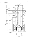
- Fig. 3 shows a basic structure of an exhaust gas purifier provided in a branch type exhaust gas passage in which the exhaust gas passage 2 is branched into a plurality of sections, in accordance with a third embodiment of the present invention.
- the exhaust gas passage 2 of the internal combustion engine 1 or the combustion equipment is branched into, for example, first and second branch exhaust gas passages 2a and 2b, a switching valve 20 is arranged in the upstream side branch portion, and the branch exhaust gas passages 2a and 2b are again combined in a downstream side end portion so as to be connected to a downstream side exhaust gas passage 2c.
- the structure is made such that the exhaust gas from the internal combustion engine 1 can be selectively discharged to one of the branch exhaust gas passages 2a and 2b by switching eh switching valve 20.
- the same NOx adsorbent 4 as that of the case in Fig. 1 is arranged within each of the branch exhaust gas passages 2a and 2b, the combustion apparatus 5 constituted by the fuel nozzle 6, the igniter 7 and the air supply means 15 is arranged in the same manner as Fig. 2 in the exhaust downstream side of each of the NOx adsorbing substances 4, and the over-rich combustion region X1 and the lean fuel combustion region X2 are formed in the exhaust gas upstream side of the air supply means 15, in the actuated state of the combustion apparatus 5.
- the adsorbent desorbing means 3 is constituted by an adsorbent desorbing fuel nozzle (burner) 31, an adsorbent desorbing igniter 32 and an adsorbent desorbing air supply means 33.
- the adsorbent desorbing fuel nozzle 31 is connected to the fuel amount regulating apparatus 10, and the adsorbent desorbing air supply means 33 is connected to the air amount regulating apparatus 16.
- the other structures as the same as the structures in Fig. 2, and the same reference numerals are attached to the same parts and portions.
- the exhaust gas from the internal combustion engine 1 is interrupted, and the first branch exhaust gas passage 2a in the regenerating operation state becomes in a state of being independently actuated from the second branch exhaust gas passage 2b in the normal operation state, and is operated so as to regenerate on the basis of the fuel supply and the air supply from the adsorbed substance desorbing means 3. Accordingly, it is possible to set the air amount for desorbing the adsorbed substance and for the combustion apparatus regardless of the amount of the exhaust gas from the internal combustion engine 1, and it is possible to save the fuel supply amount from the adsorbed substance desorbing means 3 and the fuel supply amount in the combustion apparatus 5.
- the NOx adsorbing amount of the NOx adsorbent 4 in the second branch exhaust gas passage 2b reaches a predetermined amount (for example, a saturated amount), the switching valve 20 is switched to the first branch exhaust gas passage 2a side so as to stop the combustion apparatus 5 and the adsorbed substance desorbing means 3 within the first branch exhaust gas passage 2a, and set the combustion apparatus 5 and the adsorbed substance desorbing means 3 in the second branch exhaust gas passage 2b in an actuated state.
- the normal operation is executed in the first branch exhaust gas passage 2a
- the regenerating operation is executed simultaneously in the second branch exhaust gas passage 2b.
- the exhaust gas purifier in the branch type exhaust gas passage it is possible to execute the regenerating operation of the remaining branch exhaust gas passage while executing the normal operation of the internal combustion engine 1 by utilizing one branch exhaust gas passage, and it is not necessary to specially secure a time for the regenerating operation.
- Fig. 4 shows a fourth embodiment in accordance with the present invention.
- the fourth embodiment is based on the exhaust gas purifier provided in the branch type exhaust gas passage shown in Fig. 3, and is provided with the fuel nozzle 31, the air supply means 33 and an oxidizing catalyst 35 as the adsorbed substance desorbing means 3.
- the other structures are the same as those in Fig. 3, and the same reference numerals are attached to the same parts and portions.
- Fig. 5 shows a fifth embodiment in accordance with the present invention.
- the fifth embodiment is based on the exhaust gas purifier provided in the single type exhaust gas passage shown in Fig. 1, and is structured such that the fuel nozzle 6, the igniter 7 and the air supply means 15 are provided as the combustion apparatus 5 in the same manner as Fig. 2 mentioned above, the over-rich combustion region X1 is formed in the exhaust gas upstream side of the air supply means 15, and the lean fuel combustion region X2 is formed in the exhaust gas downstream side of the air supply means 15. Further, the fuel nozzle 31 and the igniter 32 are provided as the adsorbed substance desorbing means 3.
- the other structures are the same as the structures in Figs. 1 and 2, and the same reference numerals are attached to the same parts and portions.
- An operation is basically the same as that of the Figs. 1 and 2, however, since the combustion is utilized as the adsorbed substance desorbing means 3, it is possible to change the exhaust gas to a high temperature in a moment of time, and it is possible to flexibly correspond to various conditions by regulating the fuel supply amount and the air supply amount of the adsorbed substance desorbing means 3.
- Fig. 6 shows a sixth embodiment in accordance with the present invention.
- the sixth embodiment is based on the exhaust gas purifier provided in the branch type exhaust gas passage shown in Fig. 3 mentioned above, and each of the branch exhaust gas passages 2a and 2b is structured such that a fine particle filter 40 is arranged between the adsorbed substance desorbing means (the combustion apparatus) 3 and the adsorbent 4, in addition to the basic structure.
- the other structures are the same as the structures in Fig. 3, and the same reference numerals are attached to the same parts and portions.
- An operation is basically the same as that of the case in Fig. 3 mentioned above, however, since the fine particle filter 40 is arranged in the upstream side of the NOx adsorbent 4, it is possible to flow the exhaust gas from which the particulate substance is removed by the fine particle filter 40 in the NOx adsorbent 4, at a time of the normal operation (at a time of being utilized as the exhaust gas flow path), and it is possible to prevent the adsorbing rate of the NOx by the NOx adsorbent 4 from being lowered.
- the fine particle filter 40 is regenerated by switching to the regenerating operation, and burning and removing the particulate substance on the basis of the combustion of the adsorbed substance desorbing means 3, and the NOx adsorbent 4 is simultaneously regenerated by desorbing the NOx in the NOx adsorbent 4.
- the fine particle filter 40 is preferably structured such as to have the function of only capturing the particulate substance, however, may be structured such as to include the catalyst having the oxidizing operation and have a function capable of continuously oxidizing the particulate substance.
- Fig. 7 shows a seventh embodiment in accordance with the present invention.
- the seventh embodiment is structured such that an SOx adsorbent 42 is added to the exhaust gas purifier provided in the branch type exhaust gas passage shown in Fig. 6 mentioned above.
- the SOx adsorbent 42 is arranged between the fine particle filter 40 and the NOx adsorbent 4, within each of the branch exhaust gas passages 2a and 2b.
- the other structures are the same as the structures in Fig. 6 (and Fig. 3), and the same reference numerals are attached to the same parts and portions.
- the SOx adsorbent 42 operates without problem even if the SOx adsorbent 42 is arranged in the upstream side of the fine particle filter 40.
- the SOx adsorbed to the SOx adsorbent 42 at a time of the normal operation is desorbed on the basis of a combustion heat of the adsorbed substance desorbing means 3 at a time of the regenerating operation, whereby the SOx adsorbent 42 is regenerated.
- Fig. 8 shows an eighth embodiment in accordance with the present invention.
- the eighth embodiment is based on the exhaust gas purifier provided in the branch type exhaust gas passage shown in Fig. 3 mentioned above, and is structured such that an oxidizing catalyst 47 is arranged in the downstream side of the air supply means 15 of the combustion apparatus 5 in place of forming the lean fuel combustion region, in the basic structure.
- the other structures are the same as the structures in Fig. 3, and the same reference numerals are attached to the same parts and portions.
- the oxidizing catalyst 47 is arranged in place of the lean fuel combustion region, it is possible to oxide and remove the unburned combustible such as HC, CO or the like even in the case that the temperature is comparatively low.
- Fig. 9 shows a ninth embodiment in accordance with the present invention.
- the ninth embodiment is based on the exhaust gas purifier provided in the branch type exhaust gas passage shown in Fig. 3 mentioned above, and is structured such that an exhaust gas cooling means 50 and a temperature sensor 50a are arranged in an upstream side of the switching valve 20, in addition to the basis structure.
- the temperature sensor 50a is connected to the ECU 12 so as to input a detected temperature.
- the other structures are the same as the structures in Fig. 3, and the same reference numerals are attached to the same parts and portions.
- the exhaust gas temperature flowing in the NOx adsorbent 4 is measured, and the exhaust gas cooling means 50 is controlled in such a manner that the temperature of the exhaust gas flowing in the NOx adsorbent 4 is kept within a range in which the adsorbing capacity by the NOx adsorbent 4 can be efficiently achieved.
- the control temperature of the exhaust gas is controlled in such a manner as to correspond to the NOx adsorbent 4 having various active temperature bands.
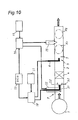
- Fig. 10 shows a tenth embodiment in accordance with the present invention.
- the tenth embodiment is based on the exhaust gas purifier provided in the single type exhaust gas passage shown in Fig. 1 mentioned above, is provided with the fuel nozzle 6 and the igniter 7 as the combustion apparatus 5 in the same manner as Fig. 1 mentioned above, and is additionally provided with the air supply means 15 in the exhaust gas downstream side of the fuel nozzle 6 in the same manner as Fig. 2, whereby the over-rich combustion region X1 is formed in the exhaust gas upstream side of the air supply means 15, and the lean fuel combustion region X1 is formed in the exhaust gas downstream side of the air supply means 15.
- the frame from the fuel nozzle 31 is held by partially isolating the exhaust gas flow from the exhaust gas upstream side, and delaying the flow rate or forming a back flow region (vortex), by the frame holding mechanism 52.
- the frame holding mechanism 52 can be structured such that an exhaust gas circulation region is formed by arranging a swirling vane and swirling the exhaust gas. Further, the structure can be made such that a high oxygen concentration region is formed in a leading end portion of the fuel nozzle 31 by supplying a small amount of air to a portion near the leading end portion of the fuel nozzle 31 by the air supply means 51 in Fig. 10.
- Fig. 11 shows an eleventh embodiment in accordance with the present invention.
- the eleventh embodiment is based on the exhaust gas purifier provided in the branch type exhaust gas passage shown in Fig. 3 mentioned above, and is structured such that only the air supply means 33 is provided as the adsorbed substance desorbing means 3, a heat exchanger 55 is arranged in a downstream side of the lean fuel combustion region X2 of the combustion apparatus 5, and the heat exchanger 55 is connected to the air supply means 33 of the adsorbed substance desorbing means 3, in the basic structure.
- the other structures are the same as the structures in Fig. 3, and the same reference numerals are attached to the same parts and portions.
- the NOx in the NOx adsorbent 4 is desorbed at a time of the regenerating operation, by exchanging the exhaust gas heated up in the lean fuel combustion region X2 of the combustion apparatus 5 for the air from the air amount regulating apparatus 16 by the heat exchanger 55, and supplying the high-temperature air to an exhaust gas upstream end portion of the branch exhaust gas passage 2a (or 2b) via the air supply means 33 of the adsorbed substance desorbing means 3.
- the igniter and the fuel nozzle are not necessary as the adsorbed substance desorbing means 3, and it is possible to achieve a compact structure. Further, a frame temperature in the over-rich combustion region X1 becomes higher, and the NOx reducing rate is improved.
- Fig. 12 shows a twelfth embodiment in accordance with the present invention.
- the twelfth embodiment is based on the exhaust gas purifier provided in the branch type exhaust gas passage shown in Fig. 3 mentioned above, and is structured such that an outlet side switching valve 58 is arranged in an exhaust gas downstream side assembled portion of the branch exhaust gas passages 2a and 2b, an atmospheric air releasing passage (an atmospheric air releasing portion) 60 is formed in a downstream side of each of the combustion apparatuses 5 in a branched manner, and an opening and closing valve 61 is provided in each of the atmospheric air passages 60, in addition to the basis structure.
- an outlet side switching valve 58 is arranged in an exhaust gas downstream side assembled portion of the branch exhaust gas passages 2a and 2b
- an atmospheric air releasing passage (an atmospheric air releasing portion) 60 is formed in a downstream side of each of the combustion apparatuses 5 in a branched manner
- an opening and closing valve 61 is provided in each of the atmospheric air passages 60, in addition to
- the exhaust gas passage 2c in the downstream side of the outlet side switching valve 58 is connected, for example, to an exhaust gas boiler 63, thereby utilizing a waste heat of the exhaust gas.
- the other structures are the same as the structures in Fig. 3, and the same reference numerals are attached to the same parts and portions.
- the NOx adsorbent 4 a substance capable of sufficiently adsorbing the SOx is utilized.
- a state shown in Fig. 12 corresponds to a state of switching both the switching valves 20 and 59 to the second branch exhaust gas passage 2b side, releasing the atmospheric air releasing passage 60 of the first branch exhaust gas passage 2a and closing the atmospheric air releasing passage 60 of the second branch exhaust gas passage 2b, the combustion apparatus 5 and the adsorbed substance desorbing means 3 in the first branch exhaust gas passage 2a are in the actuated state for the regenerating operation, and the combustion apparatus 5 and the adsorbed substance desorbing means 3 in the second branch exhaust gas passage 2b are in the non-actuated state as the exhaust gas flow path from the internal combustion engine 1.
- the SOx is desorbed together with the NOx adsorbed to the NOx adsorbent 4 at a time of the preceding operation, in the first branch exhaust gas passage 2a in the reproducing operation state, so that there is a possibility that the exhaust gas boiler 63 is poisoned if the fuel is utilized in the exhaust gas boiler 63 as it is. Accordingly, the exhaust gas is not utilized in the exhaust gas boiler 63 by being discharged to the atmospheric air from the atmospheric air releasing passage 60.
- the SOx is adsorbed to the NOx adsorbent 4 in the second branch exhaust gas passage 2b in the normal operation state, the SOx is hardly contained in the exhaust gas in the downstream side of the NOx adsorbent 4, and the exhaust gas is utilized for the exhaust gas boiler 63. Accordingly, there is no fear that the exhaust gas boiler 63 is corroded by the acid or the like caused by the SOx, it is possible to recover the heat from the exhaust gas to the low temperature, and a heat recovery rate is widely improved.
- Fig. 13 shows a thirteenth embodiment in accordance with the present invention.
- the thirteenth embodiment corresponds to a modified embodiment of the exhaust gas purifier provided in the branch type exhaust gas passage shown in Fig. 12 mentioned above, and is structured such that the exhaust gas passage 2c connected to the exhaust gas boiler 63 and an atmospheric air passage 70 communicating with the atmospheric air are provided in the outlet side switching valve 58 in the exhaust gas downstream side assembled portion, in place of forming the atmospheric air releasing passage 60 in each of the branch exhaust gas passages 2a and 2b as shown in Fig. 12.
- the branch exhaust gas passage (the second branch exhaust gas passage 2b in Fig.
- the structure in the normal operation side communicating with the internal combustion engine 1 is connected to the exhaust gas boiler 63, and the branch exhaust gas passage (the first branch exhaust gas passage 2a in Fig. 13) in the regenerating operation side is communicated with the atmospheric air passage 70.
- the structure can be simplified in comparison with the structure in which the atmospheric air releasing passage 60 and the opening and closing valve 61 are provided respectively in the branch exhaust gas passages 2a and 2b as shown in Fig. 12. An operation thereof is the same as the case in Fig. 12.
- Fig. 14 shows a fourteenth embodiment in accordance with the present invention.
- the fourteenth embodiment is based on the exhaust gas purifier provided in the single type exhaust gas passage shown in Fig. 1 mentioned above, and is structured such that a suitable control can be executed by arranging various sensors in the single exhaust air passage type basic structure. Accordingly, the same reference numerals are attached to the same parts and portions in Fig 1.
- Fig. 14 shows a fourteenth embodiment in accordance with the present invention.
- the fourteenth embodiment is based on the exhaust gas purifier provided in the single type exhaust gas passage shown in Fig. 1 mentioned above, and is structured such
- an adsorbed amount detecting (estimating) sensor 80 is arranged in the downstream side of the NOx adsorbent 4
- a temperature sensor 82 is arranged in the upstream side of the NOx adsorbent 4
- each of the sensors 80 and 82 is connected to the ECU 12
- each of the measured values is input to the ECU 12, and the following control is executed on the basis of the input value.
- the NOx in the exhaust gas is adsorbed by the NOx adsorbent 4 as mentioned above, and the unburned compatible such as CO, HC or the like is oxidized, for example, by the catalyst component contained in the NOx adsorbent 4 and having the oxidizing operation so as to be defused.
- the adsorbed substance desorbing means 3 is actuated on the basis of the command from the ECU 12, and the NOx is desorbed, and reduced and removed in the over-rich combustion region X1 of the downstream fuel apparatus 5, for example, by heating up the NOx adsorbent 4.
- the CO or the HC discharged from the internal combustion engine 1 or the combustion equipment, or the CO, the HC or the particulate substance generated in the over-rich combustion region X1 is oxidized and removed in the lean fuel combustion region X2 formed outside the over-rich combustion region X1 of the combustion apparatus 5.
- the shape of the NOx adsorbent 4 is formed in a shape suitable for capturing the particulate substance, the particulate substance is captured by the NOx adsorbent 4 during the normal operation, however, can be burned and removed by heating up the NOx adsorbent 4 as mentioned above, in the regenerating operation.
- the NOx adsorbent 4 is regenerated by heating the NOx adsorbent 4 to the SOx desorbing temperature or desorbing the SOx under the reducing atmosphere at a time of the regenerating operation.
- the NOx adsorbent 4 itself can be formed by a substance to which the SOx is hard to be adsorbed, whereby it is possible to prevent the NOx adsorbent 4 from being poisoned.
- Fig. 15 shows a fifteenth embodiment in accordance with the present invention.
- the fifteenth embodiment is based on the exhaust gas purifier provided in the branch type exhaust gas passage shown in Fig. 3 mentioned above, and is structured such that a suitable control can be executed by arranging a sensor measuring a temperature or a pressure in each of the positions in the basic structure.
- Each of the sensors 80, 81 and 82 is connected to the ECU 12, and is structured such as to input the measured value to the ECU 12.
- One of two branch exhaust gas passages 2a and 2b is utilized as the flow path of the exhaust gas from the internal combustion engine 1 for the normal operation, and the other is operated for regeneration in the mean while.
- the exhaust gas in the internal combustion engine 1 is circulated through the second branch exhaust gas passage 2b by switching the switching valve 20 to the second branch exhaust gas passage 2b side as shown in Fig. 15, and the adsorbed substance desorbing means 3 and the combustion apparatus 5 are actuated in the first branch exhaust gas passage 2a in the mean while.
- the adsorbed substance desorbing means 3 and the combustion apparatus 5 stop, and the NOx in the exhaust gas is adsorbed by the NOx adsorbent 4. Further, the unburned combustible such as CO, HC or the like is oxidized, for example, by the catalyst contained in the NOx adsorbent 4 and having the oxidizing operation so as to be defused.
- the adsorbed substance desorbing means 3 is actuated, whereby the NOx is desorbed from the NOx adsorbent 4, and is reduced and removed in the over-rich combustion region X1 in the downstream side of the exhaust gas, for example, by heating the NOx adsorbent 4.
- the switching valve 20 is changed to the first branch exhaust gas passage 2a side on the basis of the command from the ECU 12, and the second branch exhaust gas passage 2b is set to the regenerating operation state by actuating the adsorbed substance desorbing means 3 and the combustion apparatus 5 in the second branch exhaust gas passage 2b.
- the exhaust gas from the internal combustion engine 1 flows in the first branch exhaust gas passage 2a, and the normal operation state is established.
- the saturation of the particulate substance is detected by the pressure detecting sensor 81, and the switching valve 20 is switched to the first branch exhaust gas passage 2a side. Accordingly, it is possible to prevent the NOx adsorbing performance from being lowered due to the pressure reduction.
- Fig. 16 shows a time elapse of the control of the exhaust gas purifier in Fig. 15, and shows that the other executes the regenerating operation while one of the first branch exhaust gas passage 2a and the second branch exhaust gas passage 2b is utilized for the normal operation so as to adsorb the NOx.
- a relation shown in Fig. 16 is applied to all of the exhaust gas purifiers provided in the branch type exhaust gas passage in Fig. 3 or the like.
- the present invention is utilized as the exhaust gas purifier of the various internal combustion engines such as the diesel engine, the gas engine, the gasoline engine, the gas turbine engine or the like, or the combustion equipment such as the industrial boiler or the like, however, is particularly suitable for the internal combustion engine in which a lot of NOx is contained in the exhaust gas, such as the internal combustion engine operated under the lean combustion. Further, the present invention can be applied to the industrial diesel engine containing the SOx or the like, and is further suitable for the case of reusing the heat of the exhaust gas. It is possible to reduce the poisoning by the SOx and it is possible to efficiently recover the exhaust heat.
Landscapes
- Engineering & Computer Science (AREA)
- Chemical & Material Sciences (AREA)
- Combustion & Propulsion (AREA)
- Mechanical Engineering (AREA)
- General Engineering & Computer Science (AREA)
- Chemical Kinetics & Catalysis (AREA)
- Health & Medical Sciences (AREA)
- Toxicology (AREA)
- Analytical Chemistry (AREA)
- Environmental & Geological Engineering (AREA)
- Biomedical Technology (AREA)
- General Chemical & Material Sciences (AREA)
- Oil, Petroleum & Natural Gas (AREA)
- Exhaust Gas After Treatment (AREA)
- Processes For Solid Components From Exhaust (AREA)
- Treating Waste Gases (AREA)
- Exhaust Gas Treatment By Means Of Catalyst (AREA)
- Exhaust Silencers (AREA)
- Supercharger (AREA)
- Combined Controls Of Internal Combustion Engines (AREA)
- Electrical Control Of Air Or Fuel Supplied To Internal-Combustion Engine (AREA)
Applications Claiming Priority (2)
| Application Number | Priority Date | Filing Date | Title |
|---|---|---|---|
| JP2004013394A JP4413020B2 (ja) | 2004-01-21 | 2004-01-21 | 排気ガス浄化装置及びその制御方法 |
| PCT/JP2005/000521 WO2005071236A1 (ja) | 2004-01-21 | 2005-01-18 | 排気ガス浄化装置及びその制御方法 |
Publications (3)
| Publication Number | Publication Date |
|---|---|
| EP1710409A1 true EP1710409A1 (de) | 2006-10-11 |
| EP1710409A4 EP1710409A4 (de) | 2010-09-29 |
| EP1710409B1 EP1710409B1 (de) | 2012-11-28 |
Family
ID=34805382
Family Applications (1)
| Application Number | Title | Priority Date | Filing Date |
|---|---|---|---|
| EP05703758A Not-in-force EP1710409B1 (de) | 2004-01-21 | 2005-01-18 | Abgasreiniger und steuerverfahren dafür |
Country Status (7)
| Country | Link |
|---|---|
| US (1) | US7784276B2 (de) |
| EP (1) | EP1710409B1 (de) |
| JP (1) | JP4413020B2 (de) |
| KR (1) | KR100816189B1 (de) |
| CN (1) | CN100516473C (de) |
| DK (1) | DK1710409T3 (de) |
| WO (1) | WO2005071236A1 (de) |
Cited By (4)
| Publication number | Priority date | Publication date | Assignee | Title |
|---|---|---|---|---|
| EP2264292A1 (de) * | 2008-02-25 | 2010-12-22 | Yanmar Co., Ltd. | Abgasreinigungsvorrichtung |
| CN101542085B (zh) * | 2007-03-19 | 2011-08-17 | 丰田自动车株式会社 | 内燃机的排气净化装置 |
| CN101784772B (zh) * | 2007-09-21 | 2012-02-08 | 丰田自动车株式会社 | 内燃机的排气净化装置 |
| EP2693013A1 (de) * | 2011-03-30 | 2014-02-05 | Hitachi Zosen Corporation | Abgasreinigungsverfahren und -vorrichtung |
Families Citing this family (35)
| Publication number | Priority date | Publication date | Assignee | Title |
|---|---|---|---|---|
| KR100751458B1 (ko) * | 2006-08-30 | 2007-08-23 | 김승우 | 예열형 농축시스템 |
| JP2008114115A (ja) * | 2006-11-01 | 2008-05-22 | Miura Co Ltd | 有害物質低減システム |
| JP4665914B2 (ja) * | 2007-02-23 | 2011-04-06 | トヨタ自動車株式会社 | 内燃機関の排気浄化装置 |
| KR100814606B1 (ko) * | 2007-06-01 | 2008-03-18 | 김현성 | 가스버너를 이용한 폐열 회수용 열풍기 |
| JP2008298034A (ja) * | 2007-06-04 | 2008-12-11 | Yanmar Co Ltd | 排気ガス浄化装置 |
| JP4767909B2 (ja) * | 2007-06-04 | 2011-09-07 | ヤンマー株式会社 | 排気ガス浄化装置 |
| JP5139765B2 (ja) * | 2007-10-12 | 2013-02-06 | ボッシュ株式会社 | 還元剤供給システムの制御装置及び制御方法 |
| JP2009185763A (ja) * | 2008-02-08 | 2009-08-20 | Yanmar Co Ltd | 排気ガス浄化装置 |
| JP5285296B2 (ja) | 2008-02-22 | 2013-09-11 | ヤンマー株式会社 | 排気ガス浄化装置 |
| JP5062539B2 (ja) | 2009-01-13 | 2012-10-31 | トヨタ自動車株式会社 | 内燃機関の排気浄化装置 |
| KR20110012287A (ko) * | 2009-07-30 | 2011-02-09 | 에스케이이노베이션 주식회사 | 배기가스 유해물질 저감장치 및 이에 구비되는 버너의 연료분사량 제어 방법 |
| US8516799B2 (en) | 2009-12-23 | 2013-08-27 | Ford Global Technologies, Llc | Methods and systems for emission system control |
| US8096125B2 (en) | 2009-12-23 | 2012-01-17 | Ford Global Technologies, Llc | Methods and systems for emission system control |
| US8347611B2 (en) | 2009-12-23 | 2013-01-08 | Ford Global Technologies, Llc | Methods and systems for emission system control |
| US8347609B2 (en) | 2009-12-23 | 2013-01-08 | Ford Global Technologies, Llc | Methods and systems for emission system control |
| US8459010B2 (en) * | 2010-02-26 | 2013-06-11 | General Electric Company | System and method for controlling nitrous oxide emissions of an internal combustion engine and regeneration of an exhaust treatment device |
| US8042527B2 (en) | 2010-08-05 | 2011-10-25 | Ford Global Technologies, Llc | Coordination of HP and LP EGR |
| WO2012051273A1 (en) * | 2010-10-13 | 2012-04-19 | Cummins Intellectual Property, Inc. | Multi-leg exhaust aftertreatment system and method |
| US9062569B2 (en) * | 2010-10-29 | 2015-06-23 | General Electric Company | Systems, methods, and apparatus for regenerating a catalytic material |
| JP5864901B2 (ja) * | 2011-05-19 | 2016-02-17 | 日野自動車株式会社 | パティキュレートフィルタの手動再生方法 |
| US20130152555A1 (en) * | 2011-12-15 | 2013-06-20 | Caterpillar Inc. | Fluid injection lance with balanced flow distribution |
| US9080487B2 (en) | 2012-11-30 | 2015-07-14 | Tenneco Automotive Operating Company, Inc. | Reductant injection control system |
| US9016047B2 (en) * | 2013-02-15 | 2015-04-28 | GM Global Technologies Operations LLC | System and method for exhaust gas aftertreatment |
| US9103252B2 (en) * | 2013-03-15 | 2015-08-11 | Tenneco Automotive Operating Company Inc. | Modular exhaust treatment system |
| US20150135679A1 (en) * | 2013-11-21 | 2015-05-21 | General Electric Company | Emissions control in diesel engines |
| WO2015120618A1 (en) * | 2014-02-14 | 2015-08-20 | Tenneco Automotive Operating Company Inc. | Exhaust treatment system with soot blower |
| US9387438B2 (en) | 2014-02-14 | 2016-07-12 | Tenneco Automotive Operating Company Inc. | Modular system for reduction of sulphur oxides in exhaust |
| JP6280462B2 (ja) * | 2014-06-30 | 2018-02-14 | ヤンマー株式会社 | 排気浄化装置 |
| US10344642B2 (en) * | 2017-06-02 | 2019-07-09 | GM Global Technology Operations LLC | Systems and methods for controlling exhaust flow through dual after treatment device |
| FR3074524B1 (fr) | 2017-12-05 | 2021-03-19 | Continental Automotive France | Systeme et procede de commande d'un moteur a combustion interne muni d'un systeme de post traitement des gaz d'echappement de type a catalyse selective |
| KR101846852B1 (ko) * | 2017-12-28 | 2018-04-10 | 주식회사 라온테크 | 배기가스 처리장치 |
| FI128631B (fi) * | 2018-03-09 | 2020-09-15 | Vocci Oy | Menetelmä lämmön tuottamiseksi energialaitoksessa |
| JP2020029841A (ja) * | 2018-08-24 | 2020-02-27 | トヨタ自動車株式会社 | 内燃機関の排気浄化装置及び排気浄化方法 |
| DE112019007304T5 (de) | 2019-05-09 | 2022-02-17 | Cummins Emission Solutions Inc. | Ventilanordnung für split-flow-katalysator in eng gekoppelter bauweise |
| KR102639057B1 (ko) * | 2023-06-12 | 2024-02-21 | 화이버텍 (주) | 촉매 컨버터 재생 중에도 지속적으로 유해물질 제거가 가능한 배기가스 유해물질 저감 시스템 및 이를 이용한 배기가스 유해물질 저감 방법 |
Citations (3)
| Publication number | Priority date | Publication date | Assignee | Title |
|---|---|---|---|---|
| DE19604318A1 (de) * | 1996-02-07 | 1997-08-14 | Man Nutzfahrzeuge Ag | Verfahren zur Regenerierung eines NO¶x¶-Speicherkatalysators |
| DE19926150A1 (de) * | 1999-06-09 | 2000-12-14 | Volkswagen Ag | Vorrichtung zur Verminderung von Stickoxiden (NOx) im Abgas einer Brennkraftmaschine, insbesondere einer Diesel-Brennkraftmaschine |
| US20010004450A1 (en) * | 1996-08-19 | 2001-06-21 | Volkswagen Ag. | Spark-ignited internal combustion engine oxide gas absorbing arrangement and method |
Family Cites Families (12)
| Publication number | Priority date | Publication date | Assignee | Title |
|---|---|---|---|---|
| US4354821A (en) * | 1980-05-27 | 1982-10-19 | The United States Of America As Represented By The United States Environmental Protection Agency | Multiple stage catalytic combustion process and system |
| JPS59191809A (ja) | 1983-04-14 | 1984-10-31 | Babcock Hitachi Kk | 蒸気−ガス複合サイクルの低NOx化法およびその装置 |
| JPH088975B2 (ja) | 1989-10-20 | 1996-01-31 | 松下電器産業株式会社 | No▲下×▼除去装置 |
| GB2260279A (en) * | 1991-10-11 | 1993-04-14 | Ford Motor Co | Catalytic converter |
| US5577906A (en) * | 1993-12-22 | 1996-11-26 | Kabushiki Kaisha Toshiba | Catalyst for combustion |
| GB2304602A (en) * | 1995-08-26 | 1997-03-26 | Ford Motor Co | Engine with cylinder deactivation |
| JP2001329835A (ja) | 2000-05-19 | 2001-11-30 | Mitsui Eng & Shipbuild Co Ltd | 熱機関の排ガスから分離した窒素酸化物の処理方法 |
| JP3818916B2 (ja) | 2000-12-27 | 2006-09-06 | ヤンマー株式会社 | 排気浄化装置を備えた内燃機関 |
| JP2003027927A (ja) | 2001-07-12 | 2003-01-29 | Mitsui Eng & Shipbuild Co Ltd | 窒素酸化物浄化装置 |
| JP3925282B2 (ja) | 2002-04-16 | 2007-06-06 | トヨタ自動車株式会社 | 内燃機関の排気浄化装置 |
| JP3858749B2 (ja) | 2002-04-23 | 2006-12-20 | トヨタ自動車株式会社 | 内燃機関の排気浄化装置 |
| JP4175022B2 (ja) | 2002-05-20 | 2008-11-05 | 日産自動車株式会社 | 内燃機関の排気浄化装置 |
-
2004
- 2004-01-21 JP JP2004013394A patent/JP4413020B2/ja not_active Expired - Fee Related
-
2005
- 2005-01-18 WO PCT/JP2005/000521 patent/WO2005071236A1/ja active Application Filing
- 2005-01-18 DK DK05703758.2T patent/DK1710409T3/da active
- 2005-01-18 KR KR1020067013639A patent/KR100816189B1/ko not_active IP Right Cessation
- 2005-01-18 CN CNB2005800029028A patent/CN100516473C/zh not_active Expired - Fee Related
- 2005-01-18 EP EP05703758A patent/EP1710409B1/de not_active Not-in-force
- 2005-01-18 US US10/586,689 patent/US7784276B2/en not_active Expired - Fee Related
Patent Citations (3)
| Publication number | Priority date | Publication date | Assignee | Title |
|---|---|---|---|---|
| DE19604318A1 (de) * | 1996-02-07 | 1997-08-14 | Man Nutzfahrzeuge Ag | Verfahren zur Regenerierung eines NO¶x¶-Speicherkatalysators |
| US20010004450A1 (en) * | 1996-08-19 | 2001-06-21 | Volkswagen Ag. | Spark-ignited internal combustion engine oxide gas absorbing arrangement and method |
| DE19926150A1 (de) * | 1999-06-09 | 2000-12-14 | Volkswagen Ag | Vorrichtung zur Verminderung von Stickoxiden (NOx) im Abgas einer Brennkraftmaschine, insbesondere einer Diesel-Brennkraftmaschine |
Non-Patent Citations (1)
| Title |
|---|
| See also references of WO2005071236A1 * |
Cited By (6)
| Publication number | Priority date | Publication date | Assignee | Title |
|---|---|---|---|---|
| CN101542085B (zh) * | 2007-03-19 | 2011-08-17 | 丰田自动车株式会社 | 内燃机的排气净化装置 |
| CN101784772B (zh) * | 2007-09-21 | 2012-02-08 | 丰田自动车株式会社 | 内燃机的排气净化装置 |
| EP2264292A1 (de) * | 2008-02-25 | 2010-12-22 | Yanmar Co., Ltd. | Abgasreinigungsvorrichtung |
| EP2264292A4 (de) * | 2008-02-25 | 2014-07-02 | Yanmar Co Ltd | Abgasreinigungsvorrichtung |
| EP2693013A1 (de) * | 2011-03-30 | 2014-02-05 | Hitachi Zosen Corporation | Abgasreinigungsverfahren und -vorrichtung |
| EP2693013A4 (de) * | 2011-03-30 | 2014-09-10 | Hitachi Shipbuilding Eng Co | Abgasreinigungsverfahren und -vorrichtung |
Also Published As
| Publication number | Publication date |
|---|---|
| JP2005207281A (ja) | 2005-08-04 |
| EP1710409B1 (de) | 2012-11-28 |
| CN100516473C (zh) | 2009-07-22 |
| US20080141663A1 (en) | 2008-06-19 |
| EP1710409A4 (de) | 2010-09-29 |
| CN1910352A (zh) | 2007-02-07 |
| WO2005071236A1 (ja) | 2005-08-04 |
| KR100816189B1 (ko) | 2008-03-24 |
| DK1710409T3 (da) | 2013-01-02 |
| JP4413020B2 (ja) | 2010-02-10 |
| KR20060093350A (ko) | 2006-08-24 |
| US7784276B2 (en) | 2010-08-31 |
Similar Documents
| Publication | Publication Date | Title |
|---|---|---|
| EP1710409B1 (de) | Abgasreiniger und steuerverfahren dafür | |
| EP1865162B1 (de) | Abgasreinigungsvorrichtung | |
| EP2279785A2 (de) | Abgasreiniger | |
| KR101269383B1 (ko) | 배기가스 정화장치 | |
| JP4515217B2 (ja) | 排気ガス浄化装置の制御方法 | |
| WO2009099181A1 (ja) | 排気ガス浄化装置 | |
| KR101212376B1 (ko) | 배기가스 정화장치 | |
| JP4767909B2 (ja) | 排気ガス浄化装置 | |
| JP5282568B2 (ja) | 排気ガス浄化方法及び排気ガス浄化システム | |
| WO2009113650A1 (ja) | 排気ガス浄化装置の制御方法 | |
| JP2004176636A (ja) | 内燃機関の排気浄化装置 | |
| KR100763411B1 (ko) | 다중배열형 디젤 산화/환원 촉매변환장치 | |
| JP2009221922A (ja) | 排気ガス浄化装置 | |
| KR100734899B1 (ko) | Hc흡착촉매를 갖는 디젤엔진용 후처리시스템 및후처리방법 | |
| KR20220078253A (ko) | 가스 히트 펌프 및 그 제어방법 | |
| JP2008298034A (ja) | 排気ガス浄化装置 | |
| JP2005240566A (ja) | 排気浄化装置の制御方法 |
Legal Events
| Date | Code | Title | Description |
|---|---|---|---|
| PUAI | Public reference made under article 153(3) epc to a published international application that has entered the european phase |
Free format text: ORIGINAL CODE: 0009012 |
|
| 17P | Request for examination filed |
Effective date: 20060816 |
|
| AK | Designated contracting states |
Kind code of ref document: A1 Designated state(s): DE DK FI GB |
|
| DAX | Request for extension of the european patent (deleted) | ||
| RBV | Designated contracting states (corrected) |
Designated state(s): DE DK FI GB |
|
| A4 | Supplementary search report drawn up and despatched |
Effective date: 20100901 |
|
| RIC1 | Information provided on ipc code assigned before grant |
Ipc: F02D 43/00 20060101ALI20050808BHEP Ipc: F02D 41/04 20060101ALI20050808BHEP Ipc: F02B 37/00 20060101ALI20050808BHEP Ipc: F01N 7/08 00000000ALI20050808BHEP Ipc: F01N 3/36 20060101ALI20050808BHEP Ipc: F01N 3/28 20060101ALI20050808BHEP Ipc: F01N 3/08 20060101ALI20050808BHEP Ipc: F01N 3/02 20060101ALI20050808BHEP Ipc: F01N 3/08 20060101AFI20100826BHEP Ipc: B01D 53/56 20060101ALI20050808BHEP Ipc: B01D 53/81 20060101ALI20050808BHEP Ipc: B01D 53/94 20060101ALI20050808BHEP Ipc: F01N 3/18 20060101ALI20050808BHEP Ipc: F01N 3/20 20060101ALI20050808BHEP Ipc: F01N 3/22 20060101ALI20050808BHEP Ipc: F02D 41/38 20060101ALI20050808BHEP Ipc: F02D 41/40 20060101ALI20050808BHEP |
|
| 17Q | First examination report despatched |
Effective date: 20111026 |
|
| REG | Reference to a national code |
Ref country code: DE Ref legal event code: R079 Ref document number: 602005037175 Country of ref document: DE Free format text: PREVIOUS MAIN CLASS: F01N0003240000 Ipc: F01N0003080000 |
|
| RIC1 | Information provided on ipc code assigned before grant |
Ipc: F01N 3/18 20060101ALI20120430BHEP Ipc: F02D 41/38 20060101ALI20120430BHEP Ipc: F02B 37/00 20060101ALI20120430BHEP Ipc: F01N 3/36 20060101ALI20120430BHEP Ipc: B01D 53/56 20060101ALI20120430BHEP Ipc: B01D 53/81 20060101ALI20120430BHEP Ipc: F01N 3/22 20060101ALI20120430BHEP Ipc: F02D 41/04 20060101ALI20120430BHEP Ipc: F02D 41/40 20060101ALI20120430BHEP Ipc: F01N 3/28 20060101ALI20120430BHEP Ipc: F01N 3/20 20060101ALI20120430BHEP Ipc: B01D 53/94 20060101ALI20120430BHEP Ipc: F02D 43/00 20060101ALI20120430BHEP Ipc: F01N 3/02 20060101ALI20120430BHEP Ipc: F01N 3/08 20060101AFI20120430BHEP |
|
| GRAP | Despatch of communication of intention to grant a patent |
Free format text: ORIGINAL CODE: EPIDOSNIGR1 |
|
| GRAS | Grant fee paid |
Free format text: ORIGINAL CODE: EPIDOSNIGR3 |
|
| GRAA | (expected) grant |
Free format text: ORIGINAL CODE: 0009210 |
|
| AK | Designated contracting states |
Kind code of ref document: B1 Designated state(s): DE DK FI GB |
|
| REG | Reference to a national code |
Ref country code: GB Ref legal event code: FG4D |
|
| REG | Reference to a national code |
Ref country code: DK Ref legal event code: T3 |
|
| REG | Reference to a national code |
Ref country code: DE Ref legal event code: R096 Ref document number: 602005037175 Country of ref document: DE Effective date: 20130124 |
|
| PLBE | No opposition filed within time limit |
Free format text: ORIGINAL CODE: 0009261 |
|
| STAA | Information on the status of an ep patent application or granted ep patent |
Free format text: STATUS: NO OPPOSITION FILED WITHIN TIME LIMIT |
|
| 26N | No opposition filed |
Effective date: 20130829 |
|
| REG | Reference to a national code |
Ref country code: DE Ref legal event code: R097 Ref document number: 602005037175 Country of ref document: DE Effective date: 20130829 |
|
| PGFP | Annual fee paid to national office [announced via postgrant information from national office to epo] |
Ref country code: DK Payment date: 20140121 Year of fee payment: 10 Ref country code: FI Payment date: 20140120 Year of fee payment: 10 |
|
| PGFP | Annual fee paid to national office [announced via postgrant information from national office to epo] |
Ref country code: GB Payment date: 20140127 Year of fee payment: 10 |
|
| REG | Reference to a national code |
Ref country code: DK Ref legal event code: EBP Effective date: 20150131 |
|
| GBPC | Gb: european patent ceased through non-payment of renewal fee |
Effective date: 20150118 |
|
| PG25 | Lapsed in a contracting state [announced via postgrant information from national office to epo] |
Ref country code: GB Free format text: LAPSE BECAUSE OF NON-PAYMENT OF DUE FEES Effective date: 20150118 Ref country code: FI Free format text: LAPSE BECAUSE OF NON-PAYMENT OF DUE FEES Effective date: 20150118 |
|
| PG25 | Lapsed in a contracting state [announced via postgrant information from national office to epo] |
Ref country code: DK Free format text: LAPSE BECAUSE OF NON-PAYMENT OF DUE FEES Effective date: 20150131 |
|
| PGFP | Annual fee paid to national office [announced via postgrant information from national office to epo] |
Ref country code: DE Payment date: 20160126 Year of fee payment: 12 |
|
| REG | Reference to a national code |
Ref country code: DE Ref legal event code: R119 Ref document number: 602005037175 Country of ref document: DE |
|
| PG25 | Lapsed in a contracting state [announced via postgrant information from national office to epo] |
Ref country code: DE Free format text: LAPSE BECAUSE OF NON-PAYMENT OF DUE FEES Effective date: 20170801 |