EP1710179B1 - Kistenstapellager - Google Patents
Kistenstapellager Download PDFInfo
- Publication number
- EP1710179B1 EP1710179B1 EP05007511A EP05007511A EP1710179B1 EP 1710179 B1 EP1710179 B1 EP 1710179B1 EP 05007511 A EP05007511 A EP 05007511A EP 05007511 A EP05007511 A EP 05007511A EP 1710179 B1 EP1710179 B1 EP 1710179B1
- Authority
- EP
- European Patent Office
- Prior art keywords
- crate
- box
- store
- holding
- grip
- Prior art date
- Legal status (The legal status is an assumption and is not a legal conclusion. Google has not performed a legal analysis and makes no representation as to the accuracy of the status listed.)
- Not-in-force
Links
Images


Classifications
-
- B—PERFORMING OPERATIONS; TRANSPORTING
- B65—CONVEYING; PACKING; STORING; HANDLING THIN OR FILAMENTARY MATERIAL
- B65G—TRANSPORT OR STORAGE DEVICES, e.g. CONVEYORS FOR LOADING OR TIPPING, SHOP CONVEYOR SYSTEMS OR PNEUMATIC TUBE CONVEYORS
- B65G57/00—Stacking of articles
- B65G57/30—Stacking of articles by adding to the bottom of the stack
- B65G57/301—Stacking of articles by adding to the bottom of the stack by means of reciprocatory or oscillatory lifting and holding or gripping devices
- B65G57/302—Stacking of articles by adding to the bottom of the stack by means of reciprocatory or oscillatory lifting and holding or gripping devices added articles being lifted to substantially stationary grippers or holders
-
- B—PERFORMING OPERATIONS; TRANSPORTING
- B65—CONVEYING; PACKING; STORING; HANDLING THIN OR FILAMENTARY MATERIAL
- B65G—TRANSPORT OR STORAGE DEVICES, e.g. CONVEYORS FOR LOADING OR TIPPING, SHOP CONVEYOR SYSTEMS OR PNEUMATIC TUBE CONVEYORS
- B65G1/00—Storing articles, individually or in orderly arrangement, in warehouses or magazines
- B65G1/02—Storage devices
- B65G1/04—Storage devices mechanical
- B65G1/0471—Storage devices mechanical with access from beneath
-
- B—PERFORMING OPERATIONS; TRANSPORTING
- B65—CONVEYING; PACKING; STORING; HANDLING THIN OR FILAMENTARY MATERIAL
- B65G—TRANSPORT OR STORAGE DEVICES, e.g. CONVEYORS FOR LOADING OR TIPPING, SHOP CONVEYOR SYSTEMS OR PNEUMATIC TUBE CONVEYORS
- B65G2201/00—Indexing codes relating to handling devices, e.g. conveyors, characterised by the type of product or load being conveyed or handled
- B65G2201/02—Articles
- B65G2201/0235—Containers
- B65G2201/025—Boxes
Definitions
- the invention relates to a box stacking storage in which boxes are stored stacked, with movably mounted on a frame holding pawls which engage for holding the respective lowest box of a box stack at a distance above the ground on two opposite sides of the box.
- Such a crate storage is, for example, from the DE 198 49 391 C2 known.
- the boxes are held in several juxtaposed and / or consecutively arranged stacks in a frame each at its lowest box by means of latches.
- a transport device that can be moved below the stored stack of boxes, boxes to be stored can be brought from below under a desired stack and / or outsourced boxes can be picked up under the respective stack.
- this box is driven by the transport device with a lifting device under the stack of boxes up and lifted by unlocking the pawls of the entire box stack by at least one box height further up.
- the pawls As soon as the pawls, for example due to gravity and / or with the help of spring force, return to the locking position, they hold the newly stored box firmly, which now forms the lowest box of the box stack.
- the lifting device can then be moved back to store new boxes down. For unloading a box, the lifting device runs empty under the stack of boxes from which the bottom box is to be removed.
- the bottom box is released and the lifting device lowers again, taking care that the pawls are brought in the second lowest box back into the locked position. It can then be removed from the bottom of the lowest box with the lifting device all the way down and over the transport device.
- the latches used in the above construction are concretely sheets which each extend over a large part along the box side and which are pivotally mounted on the frame about a pivot axis extending parallel to the longitudinal extent of the box stack row, so that they respectively fall under the influence of gravity and / or by spring force against the side wall of the respective lowest stored box in the locked position.
- the latch plates In this locking position, the latch plates each project obliquely upward into the clear space between two adjacent, the box stack row each laterally delimiting the longitudinal members of the frame and hold with its upper edge as a box on a horizontally located on the box retaining edge - as a rule a projecting at the bottom or at the upper edge of the box projections or a collar - solid.
- the pawls must be designed such that they can engage under these projections, the projections of a box to keep them safe. If only one specific type of box is used and during storage the precision in positioning the boxes within a row is sufficiently accurate, this is not a problem. Then the pawls can each be designed - z. B. the pawls cut out at its upper edge and / or formed fit - and that they can always come between the stabilizing bars on the side wall of the box for concern and the box can safely grip.
- each box side is assigned at least four holding pawls, which are movable transversely to a box wall on the relevant box side, for example displaceably and / or pivotably, and which can be controlled synchronously to remove a box held by the holding pawls from the box stack store.
- each box side is associated with at least four holding pawls. These latches are, for example, evenly distributed over the box length.
- the holding pawls are arranged in groups, for example in four holding pawls in pairs, in spaced-apart areas along the side of the box.
- each belonging to a holding pawl group or a pair of holding pawls are immediately adjacent or preferably with a short distance, which z. B. substantially equal to the thickness of a stabilizing web, arranged side by side.
- z. B. substantially equal to the thickness of a stabilizing web
- more than four retaining pawls per box side may be provided, for example, a fifth security pawl in the middle of the box or more preferably at least six pawls, preferably in turn two pawls as another group or further pair of pawls, for example in the central region and two pawls are arranged in pairs in the front and in the rear of the box.
- each box side is at least over an area of the box extending, continuous row associated with directly adjacent or in a short distance adjacent holding pawls.
- Such a holding pawl row constructed in the manner of a keyboard can virtually adapt to the contour of the side wall together with its stabilizing webs. Regardless of the position of the box as well as the position, width and number of stabilizer bars on the box side wall, it is always ensured that a sufficient number of individual holding pawls grip the box and the box is thus held securely over the entire length.
- the holding pawls preferably individually, at least over a certain area along a box wall on the relevant box side slidably mounted. In this variant, therefore, the holding pawls for holding the box according to the current position of the stabilizing webs can be adjusted so that they come to rest next to the stabilizing webs on the box wall and can grab the box.
- the box stack bearing a combination of the features of both variants, ie that each box side are associated with at least four pawls, which are controlled synchronized and individually slidably mounted transversely to a box side wall on the respective box side and / or pivotally and also still are slidably mounted along the box wall on the relevant box side.
- the holding pawls comprise in a particularly preferred embodiment, a holding pawl head, which comes into abutment with a holder of a box on the relevant box side and which tapers in the direction of the box wall. That is, the cross section of the holding pawl head parallel to the longitudinal direction of the box sidewall becomes smaller and smaller in the direction of the box wall.
- the retaining pawl heads may be formed so that they taper towards the box side wall or formed in a semicircle towards the box side wall.
- the individual holding pawls for locking ie for holding a box
- for unlocking ie for releasing a box
- the individual holding pawls associated with a box can be unlocked by means of a common unlocking mechanism and / or lockable.
- the holding pawls are movably mounted on a pawl carrier, which can be controlled to remove the box so that the pawls are unlocked together.
- the holding pawls which are assigned to different crates in a row, movably mounted on a common pawl carrier. It then reaches the control of the common jack carrier to ensure that all stored on the common jack carrier pawls are unlocked and released at the same time all associated boxes.
- the pawl carrier extends over the entire row. In this case, it is sufficient to remove the complete box row to unlock the latch carrier in one place.
- the holding pawls of a box or preferably several boxes in a row, particularly preferably all boxes in a row, with another common unlocking mechanism, for example, a parallel to the box longitudinal direction or longitudinal direction extending rod or the like may be coupled, which the individual retaining pawls in moved an unlocking or locking position.
- the holding pawls and the pawl carrier or the unlocking mechanism should preferably be designed so that the holding pawls the latch carrier or the unlocking mechanism of its own row or an adjacent row whose retaining pawls z. B. are stored on the same side member, can not block, even if the retaining pawls are pressed by a stabilizing web of the box from the locking position.
- the holding pawls and / or pawl carrier can be constructed in a variety of variants and arranged on the frame, for example, also longitudinally displaceable transversely to the box wall, z. B. resilient, be stored.
- they are designed in the form of latches, which are mounted on the frame, usually on the rows of crates each laterally bounding carriers of the frame about a horizontal, parallel to the longitudinal extent of the box sidewall pivot axis against the respective box side.
- the holding pawls engage with a top-side pawl head located on the side wall, during storage of the box horizontally extending projection, which is here usually around the bottom of the box circumferential collar, since the boxes are usually upside down, d. H. with the box opening down, to be stored in the box warehouse.
- the holding pawls are mounted in each case about a horizontal, parallel to the longitudinal extent of the box side wall extending second pivot axis against the respective box side pivotally mounted on the latch carrier. If the pawl carrier itself - as described above - are pivotable about a horizontal, parallel to the longitudinal extent of the side wall extending first pivot axis against the box side pivotally mounted on the frame, consequently the pawls are pivotable about a located on the pawl carrier second pivot axis, which in turn about the first Pivot axis of the pawl carrier is pivotally mounted on the frame.
- the head of the retaining pawl unlike a simple pivotal mounting of the retaining pawl, not only be moved along a circular path about a parallel to the box longitudinal direction pivot axis, but is similar to a coupled pendulum mounted to the first pivot axis movable.
- the individual holding pawls at least along a certain area of the box side, are mounted so as to be freely displaceable in the longitudinal extent, the box stacks are replaced by this pawl mechanism stored "floating". Therefore, tolerances in the box dimensions and the box positions during storage and retrieval can be easily compensated and it will always build a stable stack of boxes.
- the retaining pawls should be able to protrude in the locking position as far as in a row between two carriers that a certain displacement of the boxes is also possible transverse to the box longitudinal direction.
- the retaining pawls are preferably arranged on the frame of the box stack bearing and each have on their upper side at least over a longitudinally extending to the box side wall portion transverse to the box side wall to a thickness such that a distance between the pointing away from the box upper edge of a retaining pawl to an adjacent edge of the frame, for.
- the carrier or a component located thereon is smaller than the width of the upper edge of a familial largernden box.
- the retaining pawls thus each have on their upper side at least over the longitudinally extending to the box side wall portion transverse to the box side wall on such a thickness and there are two arranged on opposite box sides of a deliberatelylagernden box holding pawls arranged such that the distance of the two pointing away from the box Upper edges of the pawls is greater than a light inner dimension of the box.
- the holding pawls and / or pawl carriers are brought by gravity into a locking position, so that they at one to abut holding box or protrude into the free space between two a Kistenlager Herbert limiting straps.
- the retaining pawls and / or the pawl carrier are resiliently mounted, so that they are brought exclusively or additionally by the spring force in the locking position.
- the case-stacking storage according to the invention preferably also has a transporting device arranged under the stored boxes with a lifting device which stores boxes to be stored during operation from below into the stack of boxes and picks out boxes to be removed under the respective stack of boxes.
- the transport device comprises a switching element, which acts for the removal of a box on the respective box associated holding pawls and / or an associated pawl carrier, that the holding pawls are unlocked. It is then not necessary to control the individual pawls or latch carrier individually synchronized motor. Instead of a motor control on each row of boxes then a corresponding motor control of the switching elements is also only on the available transport device required.
- the switching element may preferably be arranged on the lifting device and z. B. during or after the startup of the lifting device under the lowest box between a first switching position for unlocking the retaining pawls and a second switching position in which the retaining pawls are not unlocked in a raised state of the lifting device, be switched back and forth.
- such a bearing can for example also have only a single row, under which the transport device extends.
- the crate stack has a plurality of juxtaposed rows for storing boxes stacks and a transport carriage extending along the rows, which is movable transversely to the rows.
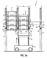
- the box pile storage 1 has a frame 4 in which boxes 2 are stored in a plurality of box stacks 3 arranged next to one another and one behind the other, ie in matrix form in rows and columns.
- the box stacks 3 are each held at their lowest box 2 by means of latch mechanisms 20 by a plurality of holding pawls 30 at a distance above the bottom B.
- the frame 4 has a plurality of parallel juxtaposed, on uprights 5 elevated side rail 6, whose distance a is greater than the width b of a suitlagernden box 2 ( FIGS. 3a to 3d ).
- longitudinal members 6 are in longitudinal extension of the carrier 6 in succession a plurality of latch mechanisms 20, which are correspondingly opposite to adjacent side members 6. These each hold a number of box stacks 3 mounted one behind the other in the longitudinal beam direction (ie in a row longitudinal direction R L ).
- Secured rods 7 extending upwards are arranged on the longitudinal members 6 which secure the box stacks 3 sideways. They can have almost any length and are preferably easily replaceable.
- Each pawl mechanism 20 consists of a pawl carrier 21 and hingedly attached individual pawls 30.
- the pawl carrier 21 extends substantially parallel to the row longitudinal direction R L a box stack row (see FIGS. 7 to 9 ) and thus parallel to a side wall 2W of each implicalagernden boxes (see FIG. 2 ).
- a pawl carrier 21 is in each case fastened pivotably about a pivot axis S 1 running parallel to the row longitudinal direction R L to retaining lugs 22, which in turn are fastened to the longitudinal members 6.
- pawl carrier 21 In this case, two mutually opposite, belonging to adjacent rows pawl carrier 21 are pivotally mounted together between two retaining tabs 22 (see Figures 2 . 5a and 5b ).
- FIG. 2 For the sake of clarity, only the pawl carrier 21 and not the individual holding pawls are shown from the front part of the pawl mechanism 20.
- FIGS. 6 . 7 and 8th For clarity, only the pawl carrier 21 shown with the associated holding pawls 30 of the box row shown in each case.
- On the image of the usually on the retaining tabs 22 - which are arranged between two rows of boxes - also stored pawl carrier of the adjacent rows of boxes has been omitted.
- the storage between the retaining tabs 22 takes place by means of two arranged at a distance from the lower end of the tabs 22 pivot pin 23, so that the pawl carrier 21 fold by gravity to the outside in a locking position (see FIG. 5a , right side).
- a stop pin 24 against which the pawl carrier 21 strike in the locked position.
- the folding down of the pawl carrier 21 in the locking position is by a supported between the pawl beams 21 of two adjacent rows extending spring 27.
- the latch carriers 21 are each equipped at their upper end opposite the pivot axis S 1 with a number of individual holding pawls 30.
- the holding pawls 30 are pivotable about a second pivot axis S 2 extending parallel to the first pivot axis S 1 of the pawl carrier 21.
- all holding pawls 30 are each provided with a bore at a distance from its lower end and mounted on a parallel to the pawl carrier 21 and to the pivot axis S 1 extending shaft 26 on the pawl carrier 21.
- the pawl carrier 21 is formed from a metal sheet, which is bent in each case on the retaining tabs 22 to form a U-profile. In the middle region of the pawl carrier 21, a further U-profile-like portion is formed, which forms a control surface 25, whose function will be explained later in more detail.
- the individual holding pawls 30 have at their upper end a pawl head 32, which comes to rest for holding a box 2 on the box side wall 2W.
- a pawl head 32 which comes to rest for holding a box 2 on the box side wall 2W.
- the circumferential collar 2K at the bottom side of the box 2 (see FIG. 2 ).
- the box 2 is securely held by the holding pawls 30 mounted on two opposite box sides on the side rails 6 and the pawl carriers 21 fastened thereto (see FIG FIGS. 3a . 4c and 7 to 9 ).
- the pivot axis S 2 is here again mounted in a height of the retaining pawls 30, so that the retaining pawls 30 tilt by gravity into the locking position, as soon as the pawl carrier 21 is folded down.
- the holding pawls 30 are supported on a surface of the pawl carrier 21 via coil springs 35. These springs 35 are each held in blind holes 34 at a distance from the lower end of the retaining pawl 30 ( FIGS. 5a to 5d ). By these springs 35, the individual holding pawls 30 are pressed relative to the pawl carrier 21 in the locking position.
- the pawls are arranged on the pawl carrier, that they are not moved by gravity, but only by the springs in the locked position.
- the individual holding pawls 30 are arranged displaceably on the shaft 26 fastened to the pawl carrier 21 in the longitudinal direction of the pivot axis S 2 .
- the pawl head 32 has a special shape.
- On the one hand there is a widening web 33 on the side of the pawl head 32 facing away from the box 2.
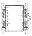
- this widening web 33 it is ensured that the holding pawls 30 each have a thickness d at their upper side, at least in the region of the widening web 33 transverse to the box side wall 2W in that the distance c between the upper edge of the holding pawl 30 leading away from the box 2 to an adjacent edge of the holding lug 22 is smaller than the width k of an upper edge of a box 2 to be stored (see FIG. 5a ).
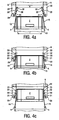
- the distance e of the two upper edges of the holding pawls 30 acting on different crate sides facing away from a crate 2 to be stored is greater than a clear inner dimension i of the crate 2 (FIG. FIG. 4a ).
- the latch heads 32 which come into contact when holding a box 2 on the box wall 2W of the relevant box side, are tapered towards the box wall 2W, ie the cross section of the latch head 32 parallel to the longitudinal extent of the box wall 2W becomes smaller and smaller. This is in FIG. 7 clearly visible. As a result, inclined surfaces are formed on the pawl head 32 as control surfaces 36.
- This special design of the pawl heads 32 has the advantage that, when a pawl head 32 with this oblique control surface 36 first encounters a stabilizing web 2S or a nose 2N on the side wall 2W of a box 2 during locking, the holding pawl displaceably mounted on the shaft 26 30 is pushed laterally away parallel to the longitudinal extension R L and yet still comes under the collar 2 K of the box 2 directly to the box wall 2W to the plant and thus the box 2 also holds.
- the entire ratchet mechanism 20 is extremely flexible and ensures secure holding of the boxes, regardless of the position exactly where the box a Stabilmaschinessteg 2S or similar elements, such as under the collar 2K on the bottom of the box located on the side wall retaining tabs for label locking, etc., having. As far as possible, the individual holding pawls 30 are automatically moved next to these disturbing elements of the box 2, without having to intervene by an external control.
- FIG. 3a shows this simplified a bearing 1 with three adjacent rows.
- a box stacking storage 1 has a considerably larger number of rows.
- box stacks 3 of the left row are four each Boxes 2 and in boxes stacks 3 of the middle row three boxes 2 stacked on each other whereas the left row is empty.
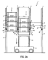
- the trolley 11 of the feeder 10 has been moved to the removal of the bottom row of boxes from the middle box stack row 3 under this middle box stack row 3, and the lifting device 12 is driven under this box stack row 3 upwards.
- each control elements 15 in the form of control pins 15 about an axis parallel to the longitudinal direction L R extending axis A are pivotally mounted.
- each latch mechanism 20 in the row is associated with a corresponding control pin 15 on the lifting device 12, wherein all control pins 15 are coupled to a shaft, so that by rotating this shaft about the pivot axis A all control pins 15 can be brought into a second switching position, in they are inclined obliquely inwards on the conveyor belt 13, or in a first position in which they are directed substantially steeply upwards.
- control pins 15 are positioned so that they respectively on the control surfaces 25 (see FIG. 2 ) the latch carrier 21 come to rest.
- the pawl carriers 21 can be pressed from the locking position into the unlocked position, this occurring synchronously for all the pawl carriers 21 in a row by the common mounting of the control pins 15 on a pivot axis A.
- the lifting device 12 moves with the control pins 15 in the first switching position upwards, so that the conveyor belt 13 rests under the lowest box 2 and preferably the box stack 3 is slightly raised to relieve the latch mechanisms 20.
- the control pins 15 By the control pins 15, the pawl carrier 21 are then brought in the relevant row in the unlocked position, so that the lower box 2 is released. Subsequently, the lifting device 12 is moved down again (see FIG.
- the boxes 2 can be transported by means of the conveyor belt 12 to a task / removal station 8 of the feeder 10.
- This task / removal station 8 extends under the frame 4 transversely in front of a front side along the trolley 11 and has a along the entire width of the box stack bearing 1 extending conveyor belt 14, via which the boxes 2 are then led out of the camp 1.
- the storage takes place in the reverse manner.
- the individual Hälagernden boxes 2 are transported and spent by means of a switch 9 at the appropriate location on the conveyor belt 13 of the trolley 11.
- the trolley 11 can then be moved to the desired position, ie under the row, in which the boxes 2 are to be stored (if the trolley is not already on the right row).
- the further storage mechanism is enlarged in the FIGS. 4a to 4c showing how the first box 2 is stored within a stack of boxes. First, the box 2 is pushed up at the appropriate place ( FIG. 4a ).
- FIG. 9 shows a further variant of a pawl carrier 21 '.
- This pawl carrier 21 ' extends substantially over the entire length of a row, so that all pawls 30 are attached in this row to only one pawl carrier 21'.
- a control pin or a similar control for example, at the front and / or at the rear end of a box stack row on the latch carrier 21 'engages synchronized to unlock all pawls 30 within the row.
Landscapes
- Engineering & Computer Science (AREA)
- Mechanical Engineering (AREA)
- Warehouses Or Storage Devices (AREA)
- Details Of Rigid Or Semi-Rigid Containers (AREA)
- Stackable Containers (AREA)
- Organic Low-Molecular-Weight Compounds And Preparation Thereof (AREA)
Priority Applications (5)
| Application Number | Priority Date | Filing Date | Title |
|---|---|---|---|
| DE502005004267T DE502005004267D1 (de) | 2005-04-06 | 2005-04-06 | Kistenstapellager |
| ES05007511T ES2308328T3 (es) | 2005-04-06 | 2005-04-06 | Almacen de apilamiento de cajas. |
| EP05007511A EP1710179B1 (de) | 2005-04-06 | 2005-04-06 | Kistenstapellager |
| AT05007511T ATE396940T1 (de) | 2005-04-06 | 2005-04-06 | Kistenstapellager |
| DE202006002326U DE202006002326U1 (de) | 2005-04-06 | 2006-02-13 | Kistenstapellager und Halteklinke für ein Kistenstapellager |
Applications Claiming Priority (1)
| Application Number | Priority Date | Filing Date | Title |
|---|---|---|---|
| EP05007511A EP1710179B1 (de) | 2005-04-06 | 2005-04-06 | Kistenstapellager |
Publications (2)
| Publication Number | Publication Date |
|---|---|
| EP1710179A1 EP1710179A1 (de) | 2006-10-11 |
| EP1710179B1 true EP1710179B1 (de) | 2008-05-28 |
Family
ID=34934802
Family Applications (1)
| Application Number | Title | Priority Date | Filing Date |
|---|---|---|---|
| EP05007511A Not-in-force EP1710179B1 (de) | 2005-04-06 | 2005-04-06 | Kistenstapellager |
Country Status (4)
| Country | Link |
|---|---|
| EP (1) | EP1710179B1 (es) |
| AT (1) | ATE396940T1 (es) |
| DE (2) | DE502005004267D1 (es) |
| ES (1) | ES2308328T3 (es) |
Families Citing this family (15)
| Publication number | Priority date | Publication date | Assignee | Title |
|---|---|---|---|---|
| DE102006038089B4 (de) * | 2006-08-14 | 2009-10-29 | Langhammer Maschinenbau Gmbh | Kistenstapler |
| CA2904263C (en) * | 2013-03-07 | 2021-03-16 | Fairfield Industries Incorporated | Item storage, dispensing, and receiving system, apparatus, methods, and applications |
| DE102013009340B4 (de) | 2013-06-04 | 2020-07-09 | Extor Gmbh | Einrichtung und Verfahren zum Ein- und Auslagern von stapelbaren Behältern |
| GB201310125D0 (en) * | 2013-06-06 | 2013-07-24 | Ocado Ltd | Storage and retrieval system |
| ITUD20130162A1 (it) * | 2013-11-29 | 2015-05-30 | Rgs Automazioni S R L | Magazzino automatizzato e relativo procedimento di immagazzinamento |
| ES2654339T3 (es) * | 2014-08-04 | 2018-02-13 | Extor Gmbh | Dispositivo de sujeción y sistema de almacenamiento para pilas de recipientes |
| DE102016125786A1 (de) * | 2016-12-28 | 2018-06-28 | Extor Gmbh | Lagersystem für Behälter sowie Behälter dafür |
| CN109095055B (zh) * | 2018-09-21 | 2023-10-03 | 浙江硕和机器人科技有限公司 | 一种自动上料输送货架 |
| CN111936398A (zh) * | 2019-02-25 | 2020-11-13 | 牧今科技 | 支架、搬运机器人以及集装箱 |
| ES2928368T3 (es) | 2019-08-23 | 2022-11-17 | Jungheinrich Ag | Disposición de almacenamiento por apilado |
| EP3974251B1 (de) * | 2020-09-25 | 2023-11-29 | Jungheinrich Aktiengesellschaft | Zustellfahrzeug |
| DE102021106213B4 (de) | 2021-03-15 | 2023-05-25 | Marbach Werkzeugbau Gmbh | Stapeleinrichtung |
| EP4159388A1 (de) * | 2021-09-29 | 2023-04-05 | Mojin Robotics GmbH | Vorrichtung mit einem greifer |
| CN115649039B (zh) * | 2022-12-22 | 2023-03-21 | 山西全城联动环保科技有限公司 | 一种废品运输机动车 |
| CN116697703B (zh) * | 2023-08-07 | 2023-10-03 | 泉州市德化县拓牌瓷业有限公司 | 一种陶瓷生产用批量烘干装置 |
Family Cites Families (3)
| Publication number | Priority date | Publication date | Assignee | Title |
|---|---|---|---|---|
| DE3047914A1 (de) * | 1980-12-19 | 1982-07-15 | Volkswagenwerk Ag, 3180 Wolfsburg | "stapelvorrichtung fuer teilebehaelter, insbesondere fuer produktionsplaetze" |
| DE19849391C2 (de) * | 1998-10-27 | 2002-02-14 | Josef Basic | Kistenstapellager |
| JP2004035145A (ja) * | 2002-07-01 | 2004-02-05 | Kanei Kogyo Kk | 自動積み上げ装置 |
-
2005
- 2005-04-06 EP EP05007511A patent/EP1710179B1/de not_active Not-in-force
- 2005-04-06 AT AT05007511T patent/ATE396940T1/de active
- 2005-04-06 DE DE502005004267T patent/DE502005004267D1/de active Active
- 2005-04-06 ES ES05007511T patent/ES2308328T3/es active Active
-
2006
- 2006-02-13 DE DE202006002326U patent/DE202006002326U1/de not_active Expired - Lifetime
Also Published As
| Publication number | Publication date |
|---|---|
| DE202006002326U1 (de) | 2006-04-27 |
| DE502005004267D1 (de) | 2008-07-10 |
| EP1710179A1 (de) | 2006-10-11 |
| ES2308328T3 (es) | 2008-12-01 |
| ATE396940T1 (de) | 2008-06-15 |
Similar Documents
| Publication | Publication Date | Title |
|---|---|---|
| EP1710179B1 (de) | Kistenstapellager | |
| DE102007040863B4 (de) | Lagerregal mit Transportvorrichtung | |
| DE19849391C2 (de) | Kistenstapellager | |
| DE1948425B2 (de) | Ein- und Auslagervorrichtung für Stapelplatten an frei wählbaren Stellen des Stapels | |
| EP1620332B1 (de) | Anordnung und verfahren zur bewirtschaftung eines warenlagers | |
| EP0734974A1 (de) | Lagerregal | |
| EP3235389B1 (de) | Behälter zum aufnehmen oder abgeben von portionen eines aus stabförmigen artikeln der tabak verarbeitenden industrie gebildeten produktmassenstroms, sowie anordnung zum diskretisieren oder bilden eines produktmassenstroms mit solchen behältern | |
| EP2746193B1 (de) | Regalfahrzeug, Regalbediengerät, Lager und entsprechendes Verfahren | |
| EP2651796B1 (de) | Logistiksystem-plattform | |
| EP3782929A1 (de) | Behälterstapellager-beschickungswagen | |
| DE202006005086U1 (de) | Stapelsäule zum Lagern oder Transportieren von Lagergütern | |
| DE102019111950B4 (de) | Stapelbare Lagereinheit und Stapel aus Lagereinheiten | |
| EP0683099B1 (de) | Leerbeutelzuführung für Verpackungsmaschine | |
| EP2700597B1 (de) | Vorrichtung und Verfahren zum Stapeln oder Entstapeln von Kisten | |
| DE102018122634A1 (de) | Ladungs-Sicherungs-System sowie Fahrzeug umfassend ein solches System und ein Verfahren zur Ladungs-Sicherung | |
| EP1837295B1 (de) | Vorrichtung mit Lagerplätzen, insbesondere zur Aufnahme von Werkstückträgern, sowie System mit einem Förderband und einer Vorrichtung zur Aufnahme von Werkstückträgern | |
| DE3632282C1 (de) | Vorrichtung zum Speichern von Abstandhalterrahmen fuer Isolierglasscheiben | |
| EP0634334B1 (de) | Lagerbehälter mit Führungselementen | |
| EP0798238A2 (de) | Lagersystem für Langgutpaletten | |
| EP0367168B1 (de) | Flaschenkasten | |
| DE19711464C2 (de) | Verfahren zum Stapeln von Transportkisten und Transportkistenstapellager | |
| AT402196B (de) | Einrichtung zum stapeln von plattenförmigen formatzuschnitten und zum abtransport des aus den formatzuschnitten gebildeten stapels | |
| DE102017102862B4 (de) | Regalbedienvorrichtung mit beweglichen Bodenteilen und Verfahren zum Entnehmen einer Wareneinheit aus einem Warenregal | |
| DE3630718A1 (de) | Zwischenspeicher fuer einzelteile | |
| DE102009043490A1 (de) | Stapelvorrichtung für leere Transportpaletten wie z.B. Euro-Paletten |
Legal Events
| Date | Code | Title | Description |
|---|---|---|---|
| PUAI | Public reference made under article 153(3) epc to a published international application that has entered the european phase |
Free format text: ORIGINAL CODE: 0009012 |
|
| AK | Designated contracting states |
Kind code of ref document: A1 Designated state(s): AT BE BG CH CY CZ DE DK EE ES FI FR GB GR HU IE IS IT LI LT LU MC NL PL PT RO SE SI SK TR |
|
| AX | Request for extension of the european patent |
Extension state: AL BA HR LV MK YU |
|
| 17P | Request for examination filed |
Effective date: 20070301 |
|
| AKX | Designation fees paid |
Designated state(s): AT BE BG CH CY CZ DE DK EE ES FI FR GB GR HU IE IS IT LI LT LU MC NL PL PT RO SE SI SK TR |
|
| GRAP | Despatch of communication of intention to grant a patent |
Free format text: ORIGINAL CODE: EPIDOSNIGR1 |
|
| GRAS | Grant fee paid |
Free format text: ORIGINAL CODE: EPIDOSNIGR3 |
|
| GRAA | (expected) grant |
Free format text: ORIGINAL CODE: 0009210 |
|
| AK | Designated contracting states |
Kind code of ref document: B1 Designated state(s): AT BE BG CH CY CZ DE DK EE ES FI FR GB GR HU IE IS IT LI LT LU MC NL PL PT RO SE SI SK TR |
|
| REG | Reference to a national code |
Ref country code: GB Ref legal event code: FG4D Free format text: NOT ENGLISH |
|
| REG | Reference to a national code |
Ref country code: CH Ref legal event code: EP |
|
| REF | Corresponds to: |
Ref document number: 502005004267 Country of ref document: DE Date of ref document: 20080710 Kind code of ref document: P |
|
| REG | Reference to a national code |
Ref country code: IE Ref legal event code: FG4D Free format text: LANGUAGE OF EP DOCUMENT: GERMAN |
|
| REG | Reference to a national code |
Ref country code: CH Ref legal event code: NV Representative=s name: PA ALDO ROEMPLER |
|
| REG | Reference to a national code |
Ref country code: CH Ref legal event code: PCAR Free format text: ALDO ROEMPLER PATENTANWALT;BRENDENWEG 11 POSTFACH 154;9424 RHEINECK (CH) |
|
| PG25 | Lapsed in a contracting state [announced via postgrant information from national office to epo] |
Ref country code: SI Free format text: LAPSE BECAUSE OF FAILURE TO SUBMIT A TRANSLATION OF THE DESCRIPTION OR TO PAY THE FEE WITHIN THE PRESCRIBED TIME-LIMIT Effective date: 20080528 |
|
| PG25 | Lapsed in a contracting state [announced via postgrant information from national office to epo] |
Ref country code: FI Free format text: LAPSE BECAUSE OF FAILURE TO SUBMIT A TRANSLATION OF THE DESCRIPTION OR TO PAY THE FEE WITHIN THE PRESCRIBED TIME-LIMIT Effective date: 20080528 |
|
| REG | Reference to a national code |
Ref country code: ES Ref legal event code: FG2A Ref document number: 2308328 Country of ref document: ES Kind code of ref document: T3 |
|
| PG25 | Lapsed in a contracting state [announced via postgrant information from national office to epo] |
Ref country code: IS Free format text: LAPSE BECAUSE OF FAILURE TO SUBMIT A TRANSLATION OF THE DESCRIPTION OR TO PAY THE FEE WITHIN THE PRESCRIBED TIME-LIMIT Effective date: 20080928 |
|
| REG | Reference to a national code |
Ref country code: IE Ref legal event code: FD4D |
|
| PG25 | Lapsed in a contracting state [announced via postgrant information from national office to epo] |
Ref country code: SE Free format text: LAPSE BECAUSE OF FAILURE TO SUBMIT A TRANSLATION OF THE DESCRIPTION OR TO PAY THE FEE WITHIN THE PRESCRIBED TIME-LIMIT Effective date: 20080828 Ref country code: PT Free format text: LAPSE BECAUSE OF FAILURE TO SUBMIT A TRANSLATION OF THE DESCRIPTION OR TO PAY THE FEE WITHIN THE PRESCRIBED TIME-LIMIT Effective date: 20081028 Ref country code: CZ Free format text: LAPSE BECAUSE OF FAILURE TO SUBMIT A TRANSLATION OF THE DESCRIPTION OR TO PAY THE FEE WITHIN THE PRESCRIBED TIME-LIMIT Effective date: 20080528 Ref country code: DK Free format text: LAPSE BECAUSE OF FAILURE TO SUBMIT A TRANSLATION OF THE DESCRIPTION OR TO PAY THE FEE WITHIN THE PRESCRIBED TIME-LIMIT Effective date: 20080528 Ref country code: IE Free format text: LAPSE BECAUSE OF FAILURE TO SUBMIT A TRANSLATION OF THE DESCRIPTION OR TO PAY THE FEE WITHIN THE PRESCRIBED TIME-LIMIT Effective date: 20080528 Ref country code: LT Free format text: LAPSE BECAUSE OF FAILURE TO SUBMIT A TRANSLATION OF THE DESCRIPTION OR TO PAY THE FEE WITHIN THE PRESCRIBED TIME-LIMIT Effective date: 20080528 |
|
| PG25 | Lapsed in a contracting state [announced via postgrant information from national office to epo] |
Ref country code: RO Free format text: LAPSE BECAUSE OF FAILURE TO SUBMIT A TRANSLATION OF THE DESCRIPTION OR TO PAY THE FEE WITHIN THE PRESCRIBED TIME-LIMIT Effective date: 20080528 Ref country code: SK Free format text: LAPSE BECAUSE OF FAILURE TO SUBMIT A TRANSLATION OF THE DESCRIPTION OR TO PAY THE FEE WITHIN THE PRESCRIBED TIME-LIMIT Effective date: 20080528 |
|
| PLBE | No opposition filed within time limit |
Free format text: ORIGINAL CODE: 0009261 |
|
| STAA | Information on the status of an ep patent application or granted ep patent |
Free format text: STATUS: NO OPPOSITION FILED WITHIN TIME LIMIT |
|
| PG25 | Lapsed in a contracting state [announced via postgrant information from national office to epo] |
Ref country code: EE Free format text: LAPSE BECAUSE OF FAILURE TO SUBMIT A TRANSLATION OF THE DESCRIPTION OR TO PAY THE FEE WITHIN THE PRESCRIBED TIME-LIMIT Effective date: 20080528 Ref country code: BG Free format text: LAPSE BECAUSE OF FAILURE TO SUBMIT A TRANSLATION OF THE DESCRIPTION OR TO PAY THE FEE WITHIN THE PRESCRIBED TIME-LIMIT Effective date: 20080828 |
|
| 26N | No opposition filed |
Effective date: 20090303 |
|
| BERE | Be: lapsed |
Owner name: REICH, KONRAD Effective date: 20090430 Owner name: BASIC, JOSEF Effective date: 20090430 |
|
| GBPC | Gb: european patent ceased through non-payment of renewal fee |
Effective date: 20090406 |
|
| REG | Reference to a national code |
Ref country code: FR Ref legal event code: ST Effective date: 20091231 |
|
| PG25 | Lapsed in a contracting state [announced via postgrant information from national office to epo] |
Ref country code: FR Free format text: LAPSE BECAUSE OF NON-PAYMENT OF DUE FEES Effective date: 20091222 Ref country code: GB Free format text: LAPSE BECAUSE OF NON-PAYMENT OF DUE FEES Effective date: 20090406 Ref country code: MC Free format text: LAPSE BECAUSE OF NON-PAYMENT OF DUE FEES Effective date: 20090430 |
|
| PG25 | Lapsed in a contracting state [announced via postgrant information from national office to epo] |
Ref country code: PL Free format text: LAPSE BECAUSE OF FAILURE TO SUBMIT A TRANSLATION OF THE DESCRIPTION OR TO PAY THE FEE WITHIN THE PRESCRIBED TIME-LIMIT Effective date: 20080528 Ref country code: BE Free format text: LAPSE BECAUSE OF NON-PAYMENT OF DUE FEES Effective date: 20090430 |
|
| PG25 | Lapsed in a contracting state [announced via postgrant information from national office to epo] |
Ref country code: GR Free format text: LAPSE BECAUSE OF FAILURE TO SUBMIT A TRANSLATION OF THE DESCRIPTION OR TO PAY THE FEE WITHIN THE PRESCRIBED TIME-LIMIT Effective date: 20080829 |
|
| PG25 | Lapsed in a contracting state [announced via postgrant information from national office to epo] |
Ref country code: IT Free format text: LAPSE BECAUSE OF NON-PAYMENT OF DUE FEES Effective date: 20090406 |
|
| PG25 | Lapsed in a contracting state [announced via postgrant information from national office to epo] |
Ref country code: LU Free format text: LAPSE BECAUSE OF NON-PAYMENT OF DUE FEES Effective date: 20090406 |
|
| PGFP | Annual fee paid to national office [announced via postgrant information from national office to epo] |
Ref country code: NL Payment date: 20110329 Year of fee payment: 7 |
|
| PG25 | Lapsed in a contracting state [announced via postgrant information from national office to epo] |
Ref country code: HU Free format text: LAPSE BECAUSE OF FAILURE TO SUBMIT A TRANSLATION OF THE DESCRIPTION OR TO PAY THE FEE WITHIN THE PRESCRIBED TIME-LIMIT Effective date: 20081129 |
|
| PGFP | Annual fee paid to national office [announced via postgrant information from national office to epo] |
Ref country code: ES Payment date: 20110318 Year of fee payment: 7 |
|
| PG25 | Lapsed in a contracting state [announced via postgrant information from national office to epo] |
Ref country code: TR Free format text: LAPSE BECAUSE OF FAILURE TO SUBMIT A TRANSLATION OF THE DESCRIPTION OR TO PAY THE FEE WITHIN THE PRESCRIBED TIME-LIMIT Effective date: 20080528 |
|
| PG25 | Lapsed in a contracting state [announced via postgrant information from national office to epo] |
Ref country code: CY Free format text: LAPSE BECAUSE OF FAILURE TO SUBMIT A TRANSLATION OF THE DESCRIPTION OR TO PAY THE FEE WITHIN THE PRESCRIBED TIME-LIMIT Effective date: 20080528 |
|
| REG | Reference to a national code |
Ref country code: NL Ref legal event code: V1 Effective date: 20121101 |
|
| PG25 | Lapsed in a contracting state [announced via postgrant information from national office to epo] |
Ref country code: NL Free format text: LAPSE BECAUSE OF NON-PAYMENT OF DUE FEES Effective date: 20121101 |
|
| PGFP | Annual fee paid to national office [announced via postgrant information from national office to epo] |
Ref country code: AT Payment date: 20120427 Year of fee payment: 8 |
|
| PGFP | Annual fee paid to national office [announced via postgrant information from national office to epo] |
Ref country code: CH Payment date: 20130619 Year of fee payment: 9 |
|
| REG | Reference to a national code |
Ref country code: ES Ref legal event code: FD2A Effective date: 20131024 |
|
| PG25 | Lapsed in a contracting state [announced via postgrant information from national office to epo] |
Ref country code: ES Free format text: LAPSE BECAUSE OF NON-PAYMENT OF DUE FEES Effective date: 20120407 |
|
| REG | Reference to a national code |
Ref country code: CH Ref legal event code: PL |
|
| REG | Reference to a national code |
Ref country code: AT Ref legal event code: MM01 Ref document number: 396940 Country of ref document: AT Kind code of ref document: T Effective date: 20140406 |
|
| PG25 | Lapsed in a contracting state [announced via postgrant information from national office to epo] |
Ref country code: LI Free format text: LAPSE BECAUSE OF NON-PAYMENT OF DUE FEES Effective date: 20140430 Ref country code: CH Free format text: LAPSE BECAUSE OF NON-PAYMENT OF DUE FEES Effective date: 20140430 |
|
| PG25 | Lapsed in a contracting state [announced via postgrant information from national office to epo] |
Ref country code: AT Free format text: LAPSE BECAUSE OF NON-PAYMENT OF DUE FEES Effective date: 20140406 |
|
| PGFP | Annual fee paid to national office [announced via postgrant information from national office to epo] |
Ref country code: DE Payment date: 20150430 Year of fee payment: 11 |
|
| REG | Reference to a national code |
Ref country code: DE Ref legal event code: R119 Ref document number: 502005004267 Country of ref document: DE |
|
| PG25 | Lapsed in a contracting state [announced via postgrant information from national office to epo] |
Ref country code: DE Free format text: LAPSE BECAUSE OF NON-PAYMENT OF DUE FEES Effective date: 20161101 |