EP1707328B1 - Portable cutting tool - Google Patents
Portable cutting tool Download PDFInfo
- Publication number
- EP1707328B1 EP1707328B1 EP20060005985 EP06005985A EP1707328B1 EP 1707328 B1 EP1707328 B1 EP 1707328B1 EP 20060005985 EP20060005985 EP 20060005985 EP 06005985 A EP06005985 A EP 06005985A EP 1707328 B1 EP1707328 B1 EP 1707328B1
- Authority
- EP
- European Patent Office
- Prior art keywords
- base
- cutting
- dust guard
- cutting tool
- circular saw
- Prior art date
- Legal status (The legal status is an assumption and is not a legal conclusion. Google has not performed a legal analysis and makes no representation as to the accuracy of the status listed.)
- Not-in-force
Links
Images


Classifications
-
- B—PERFORMING OPERATIONS; TRANSPORTING
- B23—MACHINE TOOLS; METAL-WORKING NOT OTHERWISE PROVIDED FOR
- B23Q—DETAILS, COMPONENTS, OR ACCESSORIES FOR MACHINE TOOLS, e.g. ARRANGEMENTS FOR COPYING OR CONTROLLING; MACHINE TOOLS IN GENERAL CHARACTERISED BY THE CONSTRUCTION OF PARTICULAR DETAILS OR COMPONENTS; COMBINATIONS OR ASSOCIATIONS OF METAL-WORKING MACHINES, NOT DIRECTED TO A PARTICULAR RESULT
- B23Q9/00—Arrangements for supporting or guiding portable metal-working machines or apparatus
- B23Q9/0014—Portable machines provided with or cooperating with guide means supported directly by the workpiece during action
- B23Q9/0042—Portable machines provided with or cooperating with guide means supported directly by the workpiece during action the guide means being fixed only on the workpiece
-
- B—PERFORMING OPERATIONS; TRANSPORTING
- B23—MACHINE TOOLS; METAL-WORKING NOT OTHERWISE PROVIDED FOR
- B23D—PLANING; SLOTTING; SHEARING; BROACHING; SAWING; FILING; SCRAPING; LIKE OPERATIONS FOR WORKING METAL BY REMOVING MATERIAL, NOT OTHERWISE PROVIDED FOR
- B23D59/00—Accessories specially designed for sawing machines or sawing devices
- B23D59/006—Accessories specially designed for sawing machines or sawing devices for removing or collecting chips
-
- B—PERFORMING OPERATIONS; TRANSPORTING
- B27—WORKING OR PRESERVING WOOD OR SIMILAR MATERIAL; NAILING OR STAPLING MACHINES IN GENERAL
- B27B—SAWS FOR WOOD OR SIMILAR MATERIAL; COMPONENTS OR ACCESSORIES THEREFOR
- B27B9/00—Portable power-driven circular saws for manual operation
- B27B9/04—Guiding equipment, e.g. for cutting panels
-
- Y—GENERAL TAGGING OF NEW TECHNOLOGICAL DEVELOPMENTS; GENERAL TAGGING OF CROSS-SECTIONAL TECHNOLOGIES SPANNING OVER SEVERAL SECTIONS OF THE IPC; TECHNICAL SUBJECTS COVERED BY FORMER USPC CROSS-REFERENCE ART COLLECTIONS [XRACs] AND DIGESTS
- Y10—TECHNICAL SUBJECTS COVERED BY FORMER USPC
- Y10T—TECHNICAL SUBJECTS COVERED BY FORMER US CLASSIFICATION
- Y10T83/00—Cutting
- Y10T83/667—Tool carrier or guide affixed to work during cutting
- Y10T83/68—Entirely work supported
Definitions
- the present invention relates to a portable cutting device according to the preamble of claim 1, such as a portable electric circular saw, on which a parallel ruler can be mounted.
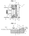
- FIG. 14 is a front view of a conventional electric circular saw
- Fig. 15 is a plan view of the conventional electric circular saw.
- reference numeral 1 denotes a base
- reference numeral 2 denotes a circular saw body that can be rotated away from the base 1 about a supporting shaft 3 with respect to the base 1, can be adjusted in cutting length of a material to be cut, and can cut the material obliquely by the saw blade 4 inclined with respect to the material, rotating about a tilt shaft (not shown).
- the circular saw body 2 has a disc-like saw blade 4 for cutting a material (not shown) to be cut, such as a plate material, and a motor (not shown) as a driving source for rotating the saw blade 4.
- a saw cover 8 is attached to a cover of a gear box 6 so as to cover the top of the saw blade 4, and a protective cover 9 is attached to the bottom of the saw blade 4 so as to expose a portion of the saw blade.
- the motor is housed in the motor housing 5, and its driving torque is reduced by a reduction gear (not shown) housed in the gear box 6 and is transmitted to a rotary shaft 7 of the saw blade 4 to rotate the saw blade 4 at a predetermined speed.
- the portable electric circular saw 11 cuts the material to be cut, by the saw blade 4 while it advances in a direction indicated by an arrow A in Fig. 15 .
- a parallel ruler 12 is often used as shown in Fig. 16 so as to accurately guide the material along the cutting direction A (for example, see JP-A-6-312902 ).
- Fig. 16 is a plan view of the conventional portable electric circular saw 11 on which the parallel ruler 12 is mounted.
- a front guide bar 13 and a rear guide bar 14 are inserted through a front insertion hole 15 and a rear insertion hole 16, respectively, formed in front and rear portions (in upper and rear portions in Fig. 16 ) of the base 1, so that they are slidable in a right-and-left direction (a direction orthogonal to the cutting direction A) and parallel to each other.
- the guide bars 13, 14 are respectively fixed to the base 1 with a first fixing screw 17 and a rear fixing screw 18.
- the parallel ruler 12 is attached parallel to an end face of the saw blade 4 between ends of both guide bars 13, 14 protruding from the base 1.
- Fig. 17 is a partial view as seen in a direction indicated by an arrow X (a view showing only a portion needed for explanation of the cutting operation) in Fig. 16 .
- the parallel ruler 12 is caused to slide along a side P1 of the material P to be cut, so that the cutting direction of the material P to be cut by the saw blade 4 can be surely guided.
- chips are generated during cutting of a material P to be cut, and the chips are scattered in a direction indicated by an arrow B by the wind induced by rotation of the saw blade 4.
- a circular saw hereinafter, referred to as a wall-edge cutting circular saw
- Figs. 18 and 19 is frequently used (see Japanese Patent No. 2933196 )
- Fig. 18 is a plan view of a wall-edge cutting circular saw
- Fig. 19 is a plan view showing a procedure of the wall-edge cutting circular saw.
- the floor material P at the wall edge when a floor material P at the wall edge is cut using the wall-edge cutting circular saw 11', the floor material P can be cut along the wall edge, in a state in which the circular saw body is rotated about the tilt shaft 3a and tilted at a predetermined angle with respect to the base 1, and the saw blade 4 protrudes outward from the side 1a of the base 1.
- the wall-edge cutting circular saw 11' can cut the floor material P along the wall edge, the side 1a of the base 1 along the direction of the wall edge is shortened in order to avoid that the side 1a of the base 1 along the direction of the wall edge interferes with a wall W.
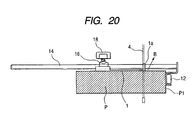
- FIG. 20 an example in which the parallel ruler 12 is mounted on the wall-edge cutting circular saw 11' and the wall-edge cutting circular saw 11' is used for cutting other than the wall-edge cutting is shown in Fig. 20 . Even in this case, chips are generated during cutting of the material P to be cut, and the chips are scattered in a direction indicated by an arrow B, by the wind induced by the rotation of the saw blade 4.
- EP-A-1 428 636 discloses a cutting tool (a portable circular saw) comprising a body 103, a base 151, a sub-base 201 and a parallel ruler 301 removably attached to the base.
- JP 2002 370203 A discloses a circular saw with a ruler 20 adjustably mounted thereto.
- JP 2002 370203 A discloses a portable cutting device according to the preamble of independent claim 1.
- a portable cutting device comprising: a cutting device body having a motor serving as a driving source and a cutting tool drivable to be rotated by the motor; and a base for guiding the cutting tool body along a surface of a material to be cut, wherein a parallel ruler can be mounted on the base, wherein front and rear guide bars respectively inserted through insertion holes formed in the base are provided with a dust guard which is able to slide parallel to an end face of the cutting tool and abut against the end face of the cutting tool, said dust guard comprising: a sliding portion slidable on the guide bars; and a guard portion disposable upward of the base depending on a position of the sliding portion, and wherein the dust guard is disposed such that its bottom face is positioned above a top face of the base.
- the dust guard is slidably supported by the guide bars inserted through the insertion holes formed in the base, and able to be fixed to the guide bars with a fixing means.
- the insertion holes formed in the base are also sub-base mounting holes.
- one side of the base is positioned in the vicinity of a side of the cutting tool, and the dust guard is disposed outside the base.
- a fixed position of the dust guard when cutting is performed with the cutting device body being rotated about a supporting shaft with respect to the base to tilt the cutting tool can be changed with respect to a fixed position of the dust guard when the cutting tool is not tilted with respect to the base.
- the parallel ruler is disposed on the same side as the dust guard or on the opposite side thereto, with the cutting tool as a boundary.
- a marker indicating the position of the cutting tool is provided in the dust guard.
- the invention provides a portable cutting tool that can prevent chips from scattering to improve the operation efficiency.
- the dust guard Since the chips collide against the bottom face of the dust guard positioned above the top face of the base and fall down, the dust guard can exhibit its function sufficiently, and consequently, scattering of chips can be surely prevented.
- the dust guard is disposed in the vicinity of the cutting tool, chips generated by cutting collide.against the dust guard, falling down and so are not scattered to the surroundings. Therefore, an operator can perform cutting operation with good operation efficiency while the chips are prevented from being stuck on the operator or impairing the visibility in cutting spots.
- the dust guard is caused to slide along the guide bars according to usage patterns of the portable cutting tool, and the dust guard can be fixed to the guide bars with the fixing means, scattering of chips can be always surely prevented by the dust guard irrespective of the usage patterns, thereby improving the operation efficiency.
- the insertion holes formed in the base are also used as sub-base mounting holes, the length of the base in the cutting direction can be reduced, and consequently, a portion left after cutting a material to be cut can be kept to a minimum.
- one side of the base is positioned in the vicinity of a side of the cutting tool. Even in this type of cutting tool, by disposing the dust guard outside the shortened one side of the base, the scattering of the chips can be surely prevented by the dust guard.
- the scattering direction of the chips when cutting is performed with the cutting tool tilted is different from scattering directions in the other cases (for example, when cutting is performed without tilting the cutting tool), the scattering of the chips can be surely prevented by the dust guard, changing the fixed position of the dust guard.
- the parallel ruler can be disposed on the same side as the dust guard or on the opposite side, with the cutting tool as a boundary, the versatility of the portable cutting tool can be improved.
- checking the position of the cutting tool by means of the marker provided in the dust guard an operator can perform cutting operation with high precision.
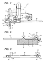
- Fig. 1 is a plan view of a portable electric circular saw according to Embodiment 1 of the invention
- Fig. 2 is a partial view as seen in a direction indicated by an arrow X (a view showing only a portion needed for explanation of cutting operation) in Fig. 1
- Fig. 3 is a plan view of a dust guard.
- the same elements in these drawings as those shown in Figs. 14 to 20 are denoted by the same reference numerals and the repetitive description thereof will be omitted.
- a portable electric circular saw 11 similar to the conventional example, the length of a front guide bar 13 and a rear guide bar 14 that are slidably inserted through a front insertion hole 15 and a rear insertion hole 16, respectively, formed in a base 1 is greater than the width of the base 1.
- a parallel ruler 12 is mounted on an end of the bars extending outward from one side of the base 1 parallel to an end face of a circular blade 4 (see Fig. 2 ).
- a dust guard 21 having an L-shaped cross section is inserted and held slidably in a direction (a right-and-left direction in Figs. 1 and 2 ) perpendicular to a cutting direction A (see Fig. 1 ).
- the dust guard 21 is disposed in the vicinity of the saw blade 4 so as to bury a gap between a circular saw body 2 (a saw cover 8) and the parallel ruler 12 and is fixed to the rear guide bar 14 with a fixing screw 22.
- both longitudinal sides of the dust guard 21 is formed with a front insertion hole 23 and a rear insertion hole 24 into which the front guide bar 13 and the rear guide bar 14 are to be inserted, respectively.
- Support brackets 25, 26 for supporting the dust guard 21 on the front guide bar 13 and the rear guide bar 14 are tied to a bottom face of the dust guard.
- the dust guard 21 is disposed such that its bottom face is positioned above a top face of the base 1.
- an operator pushes a handle 10 forward in a state in which a material P to be cut is put on the base 1, as shown in Fig. 2 and the parallel ruler 12 is caused to touch a side P1 of the material P to be cut, while the saw blade 4 is driven to rotate in a predetermined rotation direction (in a direction indicated by the arrow in Fig. 14 ) by a motor (not shown) built in the motor housing 5, whereby the portable electric circular saw 11 advances in a direction indicated by an arrow A in Fig. 1 to cut the material P to be cut by the cutting blade 4 while being accurately guided along the cutting direction by the parallel ruler 12. At this time, chips are generated by cutting of the material P to be cut.
- the chips are blown away in a direction indicated by an arrow C in Fig. 2 , by the wind induced by the rotation of the saw blade 4.
- the chips collide against the bottom face of the dust guard 21 and fall down, scattering of the chips to the surroundings is prevented.
- the operator can perform cutting operation with good operation efficiency while the chips are prevented from being stuck on the operator or impairing the visibility in cutting spots.
- the parallel ruler 12 is disposed on the same side as the dust guard 21 with respect to the saw blade 4 as a boundary.
- the parallel ruler 12 may be provided at the opposite side of the dust guard 21.
- only the fixing screw 22 is provided for fixing the dust guard 21 to the rear guide bar 14.
- a fixing screw may be provided for fixing the dust guard 21 to the front guide bar 13.
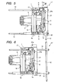
- FIGS. 5 and 6 are plan views of a wall-edge cutting circular saw according to the present embodiment
- Fig. 7 is a rear view of the wall-edge cutting circular saw
- Fig. 8 is a partial view seen in a direction indicated by an arrow X (a view showing only a portion needed for explanation of cutting operation) in Fig. 5
- Fig. 9 is a plan view of a dust guard.
- the same elements in these drawings as those shown in Figs. 1 to 4 are denoted by the same reference numerals.
- Only characterizing portions of the present embodiment will be described.
- Awall-edge cutting circular saw 11' is, for example, a saw that can cut a floor material along a wall edge.
- this circular saw one side 1a of a base 1 is shortened, and as shown in Fig. 8 , the side 1a is positioned in the vicinity of the side of a saw blade 4.
- a parallel ruler 12 is fixed to the ends of a front guide bar 13 and a rear guide bar 14 that protrude outward from the side 1a of the base 1.
- a dust guard 21 having an L-shaped cross section is inserted and held so as to bury a gap between a circular saw body 2 (a saw cover 8) and the parallel ruler 12.
- the dust guard 21 is fixed to the rear guide bar 14 with a fixing screw 22.
- Fig. 6 shows that the parallel ruler 12 is greatly pulled out of the dust guard 21.
- both longitudinal sides of the dust guard 21 is formed with a front insertion hole 23 and a rear insertion hole 24 into which the front guide bar 13 and the rear guide bar 14 to be inserted, respectively.
- Support brackets 25, 26 for supporting the dust guard 21 on the front guide bar 13 and the rear guide bar 14 are tied to a bottom face of the dust guard.
- the dust guard 21 is disposed so that its bottom face is positioned above a top face of the base 1.
- a groove 21a serving as a marker that indicates the position of the saw blade 4 is formed at a front end of the dust guard 21, and a stopper 21b is erected in the vicinity of the groove 21a.
- the stopper 21b is formed in an inverted L-shape so as to protrude horizontally toward the saw blade 4.
- the groove 21a formed at the front end of the dust guard 21 is set so as to accurately indicate the position of the saw blade 4.
- the dust guard is provided with another stopper that protrudes in a direction opposite to the stopper 21b, the position of the saw blade 4 can be accurately indicated by the groove 21a, irrespective of the mounting direction (front-and-rear direction) of the dust guard 21.
- the chips are blown away in a direction indicated by an arrow C in Fig. 8 by the wind induced by the rotation of the saw blade 4.
- the chips collides against the bottom face of the dust guard 21 and fall down, scattering of the chips to the surroundings is prevented.
- the operator can perform cutting operation with good operation efficiency while the chips are prevented from being stuck on the operator or impairing the visibility in cutting spots.
- the operator visually recognizes the groove 21a formed at the front end of the dust guard 21, whereby he/she can perform cutting operation with high accuracy while accurately grasping the position of the saw blade 4, using the groove as a marker.
- a sub base 29 having two guide bars 27, 28 similar to the front guide bar 13 and the rear guide bar 14 is used.
- the front insertion hole 15 and the rear insertion hole 16 formed in the base 1 are also used as sub-base mounting holes (holes into which the guide bars 27, 28 to be inserted), the length of the base 1 in the cutting direction (in the vertical direction in Fig. 10 ) is reduced. As a result, a portion left after cutting a material to be cut can be kept to a minimum.
- Fig. 11 is a rear view of the wall-edge cutting circular saw showing that the circular saw body is rotated with respect to the base
- Figs. 12 and 13 are partial views (views showing only a portion needed for explanation of cutting operation) showing an oblique cutting operation of a material to be cut.
- the circular saw body 2 is supported so as to be rotatable about a tilt shaft 3a with respect to the base 1.
- the fixing screw 30 is loosened, with the fixing screw 22 released, to rotate the circular saw body 2 by a predetermined degree of angle with respect to the base 1 (or to rotate the base 1 by a predetermined degree of angle with respect to the circular saw body 2) and bring the stopper 21b of the dust guard 21 into abutment against the end face of the saw cover 8.
- the saw blade 4 of the circular saw body 2 is tilted by the same angle with respect to the base 1, and in cooperation with this, the dust guard 21 is positioned at a predetermined position.
- the fixing screw 30 is disposed in a direction orthogonal to an axial direction of the tilt shaft 3a, the longitudinal length of the wall-edge cutting circular saw 11' can be reduced and the size of a portion left after cutting in wall edge cutting can be reduced.
- Fig. 12 in case cutting is performed with the saw blade 4 tilted at an angle a, in a direction shown in the figure, with respect to a material P to be cut, an operator pushes the handle 10 forward(see Fig. 11 ) in a state in which the material P to be cut is put on the base 1, and the parallel ruler 12 is caused to touch a side of the material P to be cut, while the saw blade 4 is driven to rotate by a motor (not shown).
- the wall-edge cutting circular saw 11' advances toward the reverse side of the paper of Fig. 12 to obliquely cut the material P to be cut by the cutting blade 4 while being accurately guided along the cutting direction by the parallel ruler 12.
- the dust guard 21 is moved in a direction indicated by an arrow D in Fig. 12 from the position when the material P to be cut is cut by the perpendicular saw blade 4, as shown in Fig. 8 , and is fixed to a position to cover the cutting spot of the material P to be cut from the top.
- chips are generated by cutting of the material P to be cut.
- the chips are blown away in a direction indicated by an arrow C in Fig. 12 by the wind induced by the rotation of the saw blade 4.
- the chips collides against the bottom face of the dust guard 21 and fall down, scattering of the chips to the surroundings is prevented.
- the operation efficiency can be improved.
- the dust guard 21 is moved in a direction (a direction opposite to the D direction shown in Fiq. 12) indicated by an arrow D' in Fig. 13 from the position when the material P to be cut is cut by the perpendicular saw blade 4, as shown in Fig. 8 , and is fixed to a position to cover the cutting spot of the material P to be cut from the top.
- chips are generated by cutting of the material P to be cut.
- the chips are blown away in a direction indicated by an arrow C in Fig. 13 by the wind induced by the rotation of the saw blade 4.
- the chips collide against the bottom face of the dust guard 21 and fall down, scattering of the chips to the surroundings is prevented.
- the operation efficiency can be improved.
- the portable electric circular saw 11 and the wall-edge cutting circular saw 11' relating to the invention scattering of the chips to the surroundings can be surely prevented irrespective of its usage pattern by the dust guard 21, thereby improving the operation efficiency.
- the invention can be similarly applied to other arbitrary portable cutting tools, not limited to the portable circular saw.
Landscapes
- Engineering & Computer Science (AREA)
- Mechanical Engineering (AREA)
- Life Sciences & Earth Sciences (AREA)
- Wood Science & Technology (AREA)
- Forests & Forestry (AREA)
- Sawing (AREA)
Applications Claiming Priority (1)
| Application Number | Priority Date | Filing Date | Title |
|---|---|---|---|
| JP2005091119A JP4466427B2 (ja) | 2005-03-28 | 2005-03-28 | 携帯用切断工具 |
Publications (2)
| Publication Number | Publication Date |
|---|---|
| EP1707328A1 EP1707328A1 (en) | 2006-10-04 |
| EP1707328B1 true EP1707328B1 (en) | 2009-12-16 |
Family
ID=36608560
Family Applications (1)
| Application Number | Title | Priority Date | Filing Date |
|---|---|---|---|
| EP20060005985 Not-in-force EP1707328B1 (en) | 2005-03-28 | 2006-03-23 | Portable cutting tool |
Country Status (5)
| Country | Link |
|---|---|
| US (1) | US7516551B2 (ja) |
| EP (1) | EP1707328B1 (ja) |
| JP (1) | JP4466427B2 (ja) |
| AT (1) | ATE452011T1 (ja) |
| DE (1) | DE602006011072D1 (ja) |
Families Citing this family (13)
| Publication number | Priority date | Publication date | Assignee | Title |
|---|---|---|---|---|
| JP4600184B2 (ja) * | 2005-06-30 | 2010-12-15 | 日立工機株式会社 | ガイド及びこれを備えた携帯用切断工具 |
| KR200439204Y1 (ko) * | 2007-04-27 | 2008-03-27 | 유병호 | 커터의 이동이 가능한 이동형 수동 절단기 |
| JP5061807B2 (ja) * | 2007-09-14 | 2012-10-31 | 日立工機株式会社 | 電動カッタ |
| US7950156B2 (en) * | 2008-02-19 | 2011-05-31 | Black & Decker Inc. | Power tools |
| US20100236370A1 (en) * | 2009-03-20 | 2010-09-23 | Hassenboehler Jr Charles B | Cutting aid for a motorized saw |
| US20110000081A1 (en) * | 2009-07-01 | 2011-01-06 | Wen-Chen Lee | Underwater cutting device for the handle of MTR plate-type feul |
| EP2621654A4 (en) * | 2010-09-29 | 2014-02-26 | Dino Makropoulos | UNIVERSAL EDGE GUIDANCE |
| JP5666963B2 (ja) * | 2011-04-06 | 2015-02-12 | リョービ株式会社 | 切断機 |
| CN102756165B (zh) * | 2011-04-25 | 2014-11-12 | 苏州宝时得电动工具有限公司 | 手持式切割工具 |
| DE102012218110B4 (de) * | 2012-10-04 | 2020-11-19 | Robert Bosch Gmbh | Führungssystem |
| US10486251B2 (en) * | 2016-05-16 | 2019-11-26 | Makita Corporation | Machining devices |
| DE102018113477A1 (de) * | 2018-06-06 | 2019-12-12 | Wolfcraft Gmbh | Führungsschiene mit Führungsschlitten für eine Handkreissäge |
| DE102019131527A1 (de) * | 2019-11-21 | 2021-05-27 | Mafell Ag | Handwerkzeugmaschine, insbesondere Nutfräse oder Kreissäge, insbesondere für die Holzbearbeitung |
Family Cites Families (14)
| Publication number | Priority date | Publication date | Assignee | Title |
|---|---|---|---|---|
| US166240A (en) * | 1875-08-03 | Improvement in bench-planes | ||
| US2346961A (en) * | 1941-10-13 | 1944-04-18 | Knapp Monarch Co | Electric handsaw |
| US2790468A (en) * | 1955-04-14 | 1957-04-30 | Black & Decker Mfg Co | Guard for portable power driven circular saw |
| US3043351A (en) * | 1960-09-12 | 1962-07-10 | Portable Electric Tools Inc | Edge guide for use with powered hand saws |
| JP2611618B2 (ja) * | 1993-04-30 | 1997-05-21 | 日立工機株式会社 | 携帯用電気丸鋸 |
| JP2933196B2 (ja) | 1994-10-04 | 1999-08-09 | 均 西本 | 丸 鋸 |
| US5815931A (en) * | 1996-10-29 | 1998-10-06 | Robert E. Cummings | Cutting guide for controlling the direction and cut of a hand held power cutting tool |
| US6308424B1 (en) * | 1998-07-21 | 2001-10-30 | Black & Decker Inc. | Circular saw |
| AU2001255364A1 (en) | 2000-04-12 | 2001-10-30 | Jore Corporation | Power work tools having a slim profile |
| US6543142B2 (en) * | 2001-03-21 | 2003-04-08 | Ray Floyd Bruce | Chip deflector for a circular saw |
| JP2002283301A (ja) * | 2001-03-26 | 2002-10-03 | Makita Corp | 際切りマルノコ |
| US7103979B2 (en) * | 2001-04-20 | 2006-09-12 | Hitachi Koki Co., Ltd. | Portable electric cutting device with blower mechanism |
| JP2002370203A (ja) | 2001-06-14 | 2002-12-24 | Ryobi Ltd | 丸 鋸 |
| EP1428636B1 (en) | 2002-12-10 | 2005-11-09 | Makita Corporation | Cutting tool |
-
2005
- 2005-03-28 JP JP2005091119A patent/JP4466427B2/ja not_active Expired - Fee Related
-
2006
- 2006-03-14 US US11/374,127 patent/US7516551B2/en not_active Expired - Fee Related
- 2006-03-23 EP EP20060005985 patent/EP1707328B1/en not_active Not-in-force
- 2006-03-23 DE DE200660011072 patent/DE602006011072D1/de active Active
- 2006-03-23 AT AT06005985T patent/ATE452011T1/de not_active IP Right Cessation
Also Published As
| Publication number | Publication date |
|---|---|
| JP4466427B2 (ja) | 2010-05-26 |
| JP2006272469A (ja) | 2006-10-12 |
| DE602006011072D1 (de) | 2010-01-28 |
| EP1707328A1 (en) | 2006-10-04 |
| ATE452011T1 (de) | 2010-01-15 |
| US20060213067A1 (en) | 2006-09-28 |
| US7516551B2 (en) | 2009-04-14 |
Similar Documents
| Publication | Publication Date | Title |
|---|---|---|
| EP1707328B1 (en) | Portable cutting tool | |
| KR100604698B1 (ko) | 절단톱 | |
| US6981779B2 (en) | Power tools | |
| US20210220933A1 (en) | Oscillating tool drywall blade | |
| JP4600184B2 (ja) | ガイド及びこれを備えた携帯用切断工具 | |
| EP1245357B1 (en) | Circular saw with improved corner cutting | |
| JP5366595B2 (ja) | 切断機 | |
| CN101733471A (zh) | 切割机 | |
| EP2425942A1 (en) | Guide fence and cutting machine having the same | |
| JP2018039100A (ja) | 携帯用加工機 | |
| EP1428636B1 (en) | Cutting tool | |
| JP2008188714A (ja) | 直条部材の切断装置 | |
| JP2004188738A (ja) | 切断工具 | |
| JP2017213647A (ja) | 切断機 | |
| JP2000135623A (ja) | 防塵カッター | |
| JP2013078864A (ja) | 携帯用切断機 | |
| WO2023171199A1 (ja) | 作業機 | |
| KR20010103487A (ko) | 회전톱날식 절단장치 | |
| JP2005081841A (ja) | 往復動式工具用シュー組立体 | |
| JPH10323804A (ja) | 木材加工機 | |
| JP2008200794A (ja) | 電動カッター | |
| JP5786312B2 (ja) | 携帯用切断機 | |
| JP2006297622A (ja) | 携帯用電動切断工具 | |
| JP2004345039A (ja) | 携帯用切断機 | |
| JP2018058125A (ja) | 電動工具 |
Legal Events
| Date | Code | Title | Description |
|---|---|---|---|
| PUAI | Public reference made under article 153(3) epc to a published international application that has entered the european phase |
Free format text: ORIGINAL CODE: 0009012 |
|
| AK | Designated contracting states |
Kind code of ref document: A1 Designated state(s): AT BE BG CH CY CZ DE DK EE ES FI FR GB GR HU IE IS IT LI LT LU LV MC NL PL PT RO SE SI SK TR |
|
| AX | Request for extension of the european patent |
Extension state: AL BA HR MK YU |
|
| 17P | Request for examination filed |
Effective date: 20070403 |
|
| AKX | Designation fees paid |
Designated state(s): AT BE BG CH CY CZ DE DK EE ES FI FR GB GR HU IE IS IT LI LT LU LV MC NL PL PT RO SE SI SK TR |
|
| GRAP | Despatch of communication of intention to grant a patent |
Free format text: ORIGINAL CODE: EPIDOSNIGR1 |
|
| GRAS | Grant fee paid |
Free format text: ORIGINAL CODE: EPIDOSNIGR3 |
|
| GRAA | (expected) grant |
Free format text: ORIGINAL CODE: 0009210 |
|
| AK | Designated contracting states |
Kind code of ref document: B1 Designated state(s): AT BE BG CH CY CZ DE DK EE ES FI FR GB GR HU IE IS IT LI LT LU LV MC NL PL PT RO SE SI SK TR |
|
| REG | Reference to a national code |
Ref country code: GB Ref legal event code: FG4D |
|
| REG | Reference to a national code |
Ref country code: CH Ref legal event code: EP |
|
| REG | Reference to a national code |
Ref country code: IE Ref legal event code: FG4D |
|
| REF | Corresponds to: |
Ref document number: 602006011072 Country of ref document: DE Date of ref document: 20100128 Kind code of ref document: P |
|
| REG | Reference to a national code |
Ref country code: NL Ref legal event code: VDEP Effective date: 20091216 |
|
| PG25 | Lapsed in a contracting state [announced via postgrant information from national office to epo] |
Ref country code: FI Free format text: LAPSE BECAUSE OF FAILURE TO SUBMIT A TRANSLATION OF THE DESCRIPTION OR TO PAY THE FEE WITHIN THE PRESCRIBED TIME-LIMIT Effective date: 20091216 Ref country code: LT Free format text: LAPSE BECAUSE OF FAILURE TO SUBMIT A TRANSLATION OF THE DESCRIPTION OR TO PAY THE FEE WITHIN THE PRESCRIBED TIME-LIMIT Effective date: 20091216 Ref country code: SE Free format text: LAPSE BECAUSE OF FAILURE TO SUBMIT A TRANSLATION OF THE DESCRIPTION OR TO PAY THE FEE WITHIN THE PRESCRIBED TIME-LIMIT Effective date: 20091216 |
|
| LTIE | Lt: invalidation of european patent or patent extension |
Effective date: 20091216 |
|
| PG25 | Lapsed in a contracting state [announced via postgrant information from national office to epo] |
Ref country code: SI Free format text: LAPSE BECAUSE OF FAILURE TO SUBMIT A TRANSLATION OF THE DESCRIPTION OR TO PAY THE FEE WITHIN THE PRESCRIBED TIME-LIMIT Effective date: 20091216 Ref country code: LV Free format text: LAPSE BECAUSE OF FAILURE TO SUBMIT A TRANSLATION OF THE DESCRIPTION OR TO PAY THE FEE WITHIN THE PRESCRIBED TIME-LIMIT Effective date: 20091216 Ref country code: PL Free format text: LAPSE BECAUSE OF FAILURE TO SUBMIT A TRANSLATION OF THE DESCRIPTION OR TO PAY THE FEE WITHIN THE PRESCRIBED TIME-LIMIT Effective date: 20091216 |
|
| PG25 | Lapsed in a contracting state [announced via postgrant information from national office to epo] |
Ref country code: AT Free format text: LAPSE BECAUSE OF FAILURE TO SUBMIT A TRANSLATION OF THE DESCRIPTION OR TO PAY THE FEE WITHIN THE PRESCRIBED TIME-LIMIT Effective date: 20091216 |
|
| PG25 | Lapsed in a contracting state [announced via postgrant information from national office to epo] |
Ref country code: PT Free format text: LAPSE BECAUSE OF FAILURE TO SUBMIT A TRANSLATION OF THE DESCRIPTION OR TO PAY THE FEE WITHIN THE PRESCRIBED TIME-LIMIT Effective date: 20100416 Ref country code: NL Free format text: LAPSE BECAUSE OF FAILURE TO SUBMIT A TRANSLATION OF THE DESCRIPTION OR TO PAY THE FEE WITHIN THE PRESCRIBED TIME-LIMIT Effective date: 20091216 Ref country code: BG Free format text: LAPSE BECAUSE OF FAILURE TO SUBMIT A TRANSLATION OF THE DESCRIPTION OR TO PAY THE FEE WITHIN THE PRESCRIBED TIME-LIMIT Effective date: 20100316 Ref country code: ES Free format text: LAPSE BECAUSE OF FAILURE TO SUBMIT A TRANSLATION OF THE DESCRIPTION OR TO PAY THE FEE WITHIN THE PRESCRIBED TIME-LIMIT Effective date: 20100327 Ref country code: EE Free format text: LAPSE BECAUSE OF FAILURE TO SUBMIT A TRANSLATION OF THE DESCRIPTION OR TO PAY THE FEE WITHIN THE PRESCRIBED TIME-LIMIT Effective date: 20091216 Ref country code: RO Free format text: LAPSE BECAUSE OF FAILURE TO SUBMIT A TRANSLATION OF THE DESCRIPTION OR TO PAY THE FEE WITHIN THE PRESCRIBED TIME-LIMIT Effective date: 20091216 Ref country code: IS Free format text: LAPSE BECAUSE OF FAILURE TO SUBMIT A TRANSLATION OF THE DESCRIPTION OR TO PAY THE FEE WITHIN THE PRESCRIBED TIME-LIMIT Effective date: 20100416 |
|
| PG25 | Lapsed in a contracting state [announced via postgrant information from national office to epo] |
Ref country code: SK Free format text: LAPSE BECAUSE OF FAILURE TO SUBMIT A TRANSLATION OF THE DESCRIPTION OR TO PAY THE FEE WITHIN THE PRESCRIBED TIME-LIMIT Effective date: 20091216 Ref country code: BE Free format text: LAPSE BECAUSE OF FAILURE TO SUBMIT A TRANSLATION OF THE DESCRIPTION OR TO PAY THE FEE WITHIN THE PRESCRIBED TIME-LIMIT Effective date: 20091216 Ref country code: CZ Free format text: LAPSE BECAUSE OF FAILURE TO SUBMIT A TRANSLATION OF THE DESCRIPTION OR TO PAY THE FEE WITHIN THE PRESCRIBED TIME-LIMIT Effective date: 20091216 |
|
| PLBE | No opposition filed within time limit |
Free format text: ORIGINAL CODE: 0009261 |
|
| STAA | Information on the status of an ep patent application or granted ep patent |
Free format text: STATUS: NO OPPOSITION FILED WITHIN TIME LIMIT |
|
| PG25 | Lapsed in a contracting state [announced via postgrant information from national office to epo] |
Ref country code: CY Free format text: LAPSE BECAUSE OF FAILURE TO SUBMIT A TRANSLATION OF THE DESCRIPTION OR TO PAY THE FEE WITHIN THE PRESCRIBED TIME-LIMIT Effective date: 20091216 Ref country code: GR Free format text: LAPSE BECAUSE OF FAILURE TO SUBMIT A TRANSLATION OF THE DESCRIPTION OR TO PAY THE FEE WITHIN THE PRESCRIBED TIME-LIMIT Effective date: 20100317 Ref country code: MC Free format text: LAPSE BECAUSE OF NON-PAYMENT OF DUE FEES Effective date: 20100331 |
|
| REG | Reference to a national code |
Ref country code: CH Ref legal event code: PL |
|
| 26N | No opposition filed |
Effective date: 20100917 |
|
| PG25 | Lapsed in a contracting state [announced via postgrant information from national office to epo] |
Ref country code: IE Free format text: LAPSE BECAUSE OF NON-PAYMENT OF DUE FEES Effective date: 20100323 Ref country code: DK Free format text: LAPSE BECAUSE OF FAILURE TO SUBMIT A TRANSLATION OF THE DESCRIPTION OR TO PAY THE FEE WITHIN THE PRESCRIBED TIME-LIMIT Effective date: 20091216 |
|
| PG25 | Lapsed in a contracting state [announced via postgrant information from national office to epo] |
Ref country code: CH Free format text: LAPSE BECAUSE OF NON-PAYMENT OF DUE FEES Effective date: 20100331 Ref country code: LI Free format text: LAPSE BECAUSE OF NON-PAYMENT OF DUE FEES Effective date: 20100331 |
|
| PG25 | Lapsed in a contracting state [announced via postgrant information from national office to epo] |
Ref country code: IT Free format text: LAPSE BECAUSE OF FAILURE TO SUBMIT A TRANSLATION OF THE DESCRIPTION OR TO PAY THE FEE WITHIN THE PRESCRIBED TIME-LIMIT Effective date: 20091216 |
|
| PG25 | Lapsed in a contracting state [announced via postgrant information from national office to epo] |
Ref country code: LU Free format text: LAPSE BECAUSE OF NON-PAYMENT OF DUE FEES Effective date: 20100323 Ref country code: HU Free format text: LAPSE BECAUSE OF FAILURE TO SUBMIT A TRANSLATION OF THE DESCRIPTION OR TO PAY THE FEE WITHIN THE PRESCRIBED TIME-LIMIT Effective date: 20100617 |
|
| PG25 | Lapsed in a contracting state [announced via postgrant information from national office to epo] |
Ref country code: TR Free format text: LAPSE BECAUSE OF FAILURE TO SUBMIT A TRANSLATION OF THE DESCRIPTION OR TO PAY THE FEE WITHIN THE PRESCRIBED TIME-LIMIT Effective date: 20091216 |
|
| REG | Reference to a national code |
Ref country code: FR Ref legal event code: PLFP Year of fee payment: 11 |
|
| PGFP | Annual fee paid to national office [announced via postgrant information from national office to epo] |
Ref country code: DE Payment date: 20160315 Year of fee payment: 11 |
|
| PGFP | Annual fee paid to national office [announced via postgrant information from national office to epo] |
Ref country code: GB Payment date: 20160323 Year of fee payment: 11 Ref country code: FR Payment date: 20160208 Year of fee payment: 11 |
|
| REG | Reference to a national code |
Ref country code: DE Ref legal event code: R119 Ref document number: 602006011072 Country of ref document: DE |
|
| GBPC | Gb: european patent ceased through non-payment of renewal fee |
Effective date: 20170323 |
|
| REG | Reference to a national code |
Ref country code: FR Ref legal event code: ST Effective date: 20171130 |
|
| PG25 | Lapsed in a contracting state [announced via postgrant information from national office to epo] |
Ref country code: DE Free format text: LAPSE BECAUSE OF NON-PAYMENT OF DUE FEES Effective date: 20171003 Ref country code: FR Free format text: LAPSE BECAUSE OF NON-PAYMENT OF DUE FEES Effective date: 20170331 |
|
| PG25 | Lapsed in a contracting state [announced via postgrant information from national office to epo] |
Ref country code: GB Free format text: LAPSE BECAUSE OF NON-PAYMENT OF DUE FEES Effective date: 20170323 |