EP1706991B1 - Tiled projection display using spatial light modulators - Google Patents
Tiled projection display using spatial light modulators Download PDFInfo
- Publication number
- EP1706991B1 EP1706991B1 EP05705057A EP05705057A EP1706991B1 EP 1706991 B1 EP1706991 B1 EP 1706991B1 EP 05705057 A EP05705057 A EP 05705057A EP 05705057 A EP05705057 A EP 05705057A EP 1706991 B1 EP1706991 B1 EP 1706991B1
- Authority
- EP
- European Patent Office
- Prior art keywords
- illumination
- modulated
- spatial light
- projection apparatus
- modulated light
- Prior art date
- Legal status (The legal status is an assumption and is not a legal conclusion. Google has not performed a legal analysis and makes no representation as to the accuracy of the status listed.)
- Expired - Fee Related
Links
- 230000010287 polarization Effects 0.000 claims abstract description 89
- 238000005286 illumination Methods 0.000 claims abstract description 60
- 230000003287 optical effect Effects 0.000 claims abstract description 23
- 238000003384 imaging method Methods 0.000 description 8
- 238000000034 method Methods 0.000 description 8
- 238000010586 diagram Methods 0.000 description 5
- 230000008901 benefit Effects 0.000 description 4
- 230000000694 effects Effects 0.000 description 3
- 238000013459 approach Methods 0.000 description 2
- 238000004519 manufacturing process Methods 0.000 description 2
- 238000012163 sequencing technique Methods 0.000 description 2
- 230000002123 temporal effect Effects 0.000 description 2
- 230000015572 biosynthetic process Effects 0.000 description 1
- 239000002131 composite material Substances 0.000 description 1
- 238000004883 computer application Methods 0.000 description 1
- 238000007796 conventional method Methods 0.000 description 1
- 238000002059 diagnostic imaging Methods 0.000 description 1
- 239000000835 fiber Substances 0.000 description 1
- 230000004907 flux Effects 0.000 description 1
- 239000004973 liquid crystal related substance Substances 0.000 description 1
- 238000005259 measurement Methods 0.000 description 1
- 230000007246 mechanism Effects 0.000 description 1
- 239000013307 optical fiber Substances 0.000 description 1
- 230000008520 organization Effects 0.000 description 1
- 230000004044 response Effects 0.000 description 1
- 230000000007 visual effect Effects 0.000 description 1
- 238000012800 visualization Methods 0.000 description 1
- 229910052724 xenon Inorganic materials 0.000 description 1
- FHNFHKCVQCLJFQ-UHFFFAOYSA-N xenon atom Chemical compound [Xe] FHNFHKCVQCLJFQ-UHFFFAOYSA-N 0.000 description 1
Images


Classifications
-
- H—ELECTRICITY
- H04—ELECTRIC COMMUNICATION TECHNIQUE
- H04N—PICTORIAL COMMUNICATION, e.g. TELEVISION
- H04N5/00—Details of television systems
- H04N5/222—Studio circuitry; Studio devices; Studio equipment
- H04N5/262—Studio circuits, e.g. for mixing, switching-over, change of character of image, other special effects ; Cameras specially adapted for the electronic generation of special effects
- H04N5/2624—Studio circuits, e.g. for mixing, switching-over, change of character of image, other special effects ; Cameras specially adapted for the electronic generation of special effects for obtaining an image which is composed of whole input images, e.g. splitscreen
-
- G—PHYSICS
- G02—OPTICS
- G02B—OPTICAL ELEMENTS, SYSTEMS OR APPARATUS
- G02B27/00—Optical systems or apparatus not provided for by any of the groups G02B1/00 - G02B26/00, G02B30/00
- G02B27/10—Beam splitting or combining systems
- G02B27/1066—Beam splitting or combining systems for enhancing image performance, like resolution, pixel numbers, dual magnifications or dynamic range, by tiling, slicing or overlapping fields of view
-
- G—PHYSICS
- G02—OPTICS
- G02B—OPTICAL ELEMENTS, SYSTEMS OR APPARATUS
- G02B27/00—Optical systems or apparatus not provided for by any of the groups G02B1/00 - G02B26/00, G02B30/00
- G02B27/28—Optical systems or apparatus not provided for by any of the groups G02B1/00 - G02B26/00, G02B30/00 for polarising
- G02B27/283—Optical systems or apparatus not provided for by any of the groups G02B1/00 - G02B26/00, G02B30/00 for polarising used for beam splitting or combining
-
- G—PHYSICS
- G03—PHOTOGRAPHY; CINEMATOGRAPHY; ANALOGOUS TECHNIQUES USING WAVES OTHER THAN OPTICAL WAVES; ELECTROGRAPHY; HOLOGRAPHY
- G03B—APPARATUS OR ARRANGEMENTS FOR TAKING PHOTOGRAPHS OR FOR PROJECTING OR VIEWING THEM; APPARATUS OR ARRANGEMENTS EMPLOYING ANALOGOUS TECHNIQUES USING WAVES OTHER THAN OPTICAL WAVES; ACCESSORIES THEREFOR
- G03B37/00—Panoramic or wide-screen photography; Photographing extended surfaces, e.g. for surveying; Photographing internal surfaces, e.g. of pipe
- G03B37/04—Panoramic or wide-screen photography; Photographing extended surfaces, e.g. for surveying; Photographing internal surfaces, e.g. of pipe with cameras or projectors providing touching or overlapping fields of view
-
- H—ELECTRICITY
- H04—ELECTRIC COMMUNICATION TECHNIQUE
- H04N—PICTORIAL COMMUNICATION, e.g. TELEVISION
- H04N9/00—Details of colour television systems
- H04N9/12—Picture reproducers
-
- H—ELECTRICITY
- H04—ELECTRIC COMMUNICATION TECHNIQUE
- H04N—PICTORIAL COMMUNICATION, e.g. TELEVISION
- H04N9/00—Details of colour television systems
- H04N9/12—Picture reproducers
- H04N9/31—Projection devices for colour picture display, e.g. using electronic spatial light modulators [ESLM]
- H04N9/3141—Constructional details thereof
- H04N9/3147—Multi-projection systems
Definitions
- This invention generally relates to projection imaging apparatus and more particularly relates to an apparatus and method for tiled projection display using spatial light modulators.
- U.S. Patent No. 6,262,696 discloses a large display panel having a number of precisely aligned LCD display modules arranged as tiles over a backlighting surface
- U.S. Patent No. 5,626,410 discloses tiling of LCD devices in a backlighting display using a fiber optic array for achieving more uniform brightness
- U.S. Patent No. 5,902,030 discloses a backlighting system using multiple projectors, with a screen outfitted for suitably combining images, such as using Fresnel lens. While these approaches offer some solutions for backlighting systems that form an image on a specially designed, diffusive surface, the apparatus and techniques of these patents are not suitable for front-projection systems.
- projection display apparatus employing LCD spatial light modulators present some significant challenges to tiling implementation.
- polarization states of incident illumination and modulated light must be accounted for in many types of projection apparatus using these devices.
- Projection optics must be suitable for projecting a tiled display, where tiles are adjacent, rather than overlapping as in the apparatus of U.S. Patent No. 6,585,378 and U.S. Patent No. 5,788,352 .
- the present invention provides a projection apparatus for forming a tiled image on a display surface, the tiled image comprising at least a first image tile segment and an adjacent second image tile segment, the projection apparatus comprising:
- references to components may have part numbers with appended alphabetic characters, where it is useful to describe specific optical paths, as shown in the accompanying figures. Where the discussion refers to general characteristics of components, rather than to specific optical paths, appended alphabetic characters may be omitted.
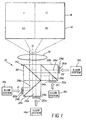
- a projection apparatus 10 for forming a tiled image 12 on a display surface 14.
- Each spatial light modulator 20a-20d has a corresponding illumination system 16a, 16b, 16c, and 16d for providing source illumination. Possible configurations for illumination systems 16a-16d are given subsequently.
- the corresponding segment of tiled image 12 (with tiled segments arranged as four contiguous quadrants numbered I, II, III, and IV) is indicated for each spatial light modulator 20a-20d.
- An arrangement of polarization beamsplitters 22a and 22b with a beamsplitter 30 is provided as a beam aligner 40 for directing a corresponding modulated light beam 26a, 26b, 26c, and 26d from each spatial light modulator 20a, 20b, 20c, and 20d respectively, along a separate path parallel to optical axis O of a projection lens 18.
- Each spatial light modulator 20a-20d is provided with an analyzer 24a, 24b, 24c, and 24d for improved contrast.
- beamsplitter 30 is not a polarization beamsplitter where shown in embodiments disclosed herein.
- Projection lens 18 directs each modulated light beam to a separate tiled segment, as a corresponding one of quadrants I, II, III, or IV. These modulated light beams must be carefully aligned adjacently to minimize gaps, unintended overlaps, or skewing of tiled quadrants I-IV.
- Figure 1 shows the relative positioning of spatial light modulators 20a-20d and their relative arrangement about beam aligner 40 components from a top view.
- Figure 2 shows relative positions of spatial light modulators 20a-20d from a side view.
- projection apparatus 10 For an understanding of how projection apparatus 10 operates, it is instructive to follow the path of modulated light for each of the four tiled quadrants I-IV in Figure 1, with reference also to the positioning of spatial light modulators 20a-20d from the side view of Figure 2:
- Adjacent modulated light beams 26a, 26b, 26c, and 26d are directed toward projection lens 18 in parallel paths to output axis O. Unlike with prior art arrangements, modulated light beams 26a, 26b, 26c, and 26d are not centered onto the same optical axis by beam-combining elements. Instead, modulated light beams 26a, 26b, 26c, and 26d are directed adjacently, in a non-overlapping manner. Certainly, some slight overlap is unavoidable between any two adjacent modulated light beams 26a, 26b, 26c, and 26d, necessary for providing a suitable join or seam between adjacent image segments of tiled image 12. However, modulated light beams 26a, 26b, 26c, and 26d themselves are directed along separate, parallel axes rather than being centered onto the same optical axis O.
- Analyzers 24a, 24b, 24c, and 24d are used in this embodiment to improve contrast for each tiled segment. Alternate arrangements for positioning analyzers 24a-24d are shown in subsequent embodiments.
- illumination systems 16a and 16b both provide polarized light along two parallel paths.
- illumination system 16a provides S-polarized light; along the other parallel path, illumination system 16a provides P-polarized light.
- This light from illumination system 16a provides source illumination to a polarization beamsplitter 28a, a wire-grid polarization beamsplitter in one embodiment.
- Polarization beamsplitter 28a separates light by its polarization state, directing light of one polarization state to polarization beamsplitter 22a for modulation by reflective spatial light modulator 20a.
- Output modulated light beam 26a from spatial light modulator 20a is then transmitted through polarization beamsplitter 22a and an analyzer 24a and through polarization beamsplitter 22e and beamsplitter 30 to projection lens 18, in a path parallel to optical axis O, for forming tiled quadrant I.
- the other polarization state from polarization beamsplitter 28a goes through a half-wave plate 42 to alter its polarization state and is reflected toward reflective spatial light modulator 20b from polarization beamsplitter 22b.
- Output modulated light beam 26b is then transmitted through polarization beamsplitter 22b and an analyzer 24b, reflected by polarization beamsplitter 22e, and transmitted through beamsplitter 30, in a path parallel to optical axis O, toward projection lens 18 for forming tiled quadrant II.
- Polarization beamsplitter 28b separates the polarized light along parallel paths from illumination system 16b by its polarization state, directing light of one polarization state to polarization beamsplitter 22c for modulation by reflective spatial-light modulator 20c.
- Output modulated light beam 26c from spatial light modulator 20c is then transmitted through polarization beamsplitter 22c and through an analyzer 24c and is reflected by polarization beamsplitter 22f and beamsplitter 30, into a path parallel to optical axis O, to projection lens 18 for forming tiled quadrant III.
- the other polarization state from polarization beamsplitter 28b is transmitted through half-wave plate 42 to alter its polarization state, and toward reflective spatial light modulator 20d from polarization beamsplitter 22d.
- Output modulated light beam 26d is then transmitted through polarization beamsplitter 22d and an analyzer 24d and through polarization beamsplitter 22f, and is reflected by beamsplitter 30 into a path parallel to optical axis O, toward projection lens 18 for forming tiled quadrant IV.
- FIG 4 there is shown a third embodiment of projection apparatus 10 of the present invention, using two separate illumination systems 16a and 16b that, in similar manner to the embodiment shown in Figure 3, provide light having orthogonal polarization states in separate paths, indicated as paths S and P.
- Polarized illumination system 16a provides light of both polarization states to polarization beamsplitter 22a, which directs the received illumination into separate paths for each polarization state.
- S path polarization state is reflected toward reflective spatial light modulator 20a by polarization beamsplitter 22a.
- Light having the P path polarization state is transmitted toward spatial light modulator 20b.
- Modulated light beams 26a and 26b are then transmitted through beamsplitter 30, along adjacent paths parallel to optical axis O, toward lens 18 for forming tiled quadrants I and II respectively (as shown in Figure 1).
- polarization beamsplitter 22b directs the received P and S path polarized illumination from illumination system 16b into separate paths for spatial light modulators 20c and 20d respectively.
- Modulated light beams 26c and 26d are then directed by polarization beamsplitter 22b and reflected by beamsplitter 30, along adjacent paths parallel to optical axis O, toward projection lens 18 for forming tiled quadrants III and IV respectively (as shown in Figure 1).
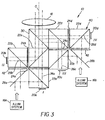
- FIG. 5 there is shown an embodiment using two reflective spatial light modulators 20a and 20b for forming tiled image 12 having two tiled sections I and II.
- Figure 5 also shows an arrangement of illumination system 16 that provides separate paths for S- and P-polarized light, as is needed for the alternative embodiments of Figures 3 and 4.
- a light source 38 such as a lamp or LED, for example, provides light to a polarization beamsplitter 32, typically through a uniformizer component of some kind, such as a lenslet array or integrator bar (not shown).
- Polarization beamsplitter 32 separates illumination into its orthogonal polarization states, and, using reflective surface 44 or a prism for redirecting light in the path of one of the polarization states, along spatially separate paths S and P.
- Lenses 36 direct this light toward a single polarization beamsplitter 22 which serves as beam aligner 40.
- Light having one polarization state is transmitted directly through polarization beamsplitter 32 along a path S for modulation by spatial light modulator 20a.
- Light having the orthogonal polarization state is reflected by polarization beamsplitter 22 for modulation by spatial light modulator 20b.
- Output modulated light is then directed from polarization beamsplitter 22 in the direction of optical axis O toward projection lens 18.
- FIG. 6 there is shown an alternate embodiment for projection using two transmissive spatial light modulators 20a and 20b for forming tiled image 12 having two tiled sections.
- polarization beamsplitter 32 and reflective surface 44 are provided as part of illumination system 16 to separate the illumination into its orthogonal polarization states, along spatially separate paths, P and S.
- Polarization beamsplitter 28 directs one polarization state to transmissive spatial light modulator 20a, reflected by a turning mirror 34 in the embodiment of Figure 6.
- Light having the orthogonal polarization state is directed through polarization beamsplitter 28 and to transmissive spatial light modulator 20b.
- Polarization beamsplitter 22, acting as beam aligner 40 then directs modulated light from both spatial light modulators 20a and 20b along adjacent paths, in the direction of optical axis O, toward projection lens 18.
- the embodiments described hereinabove perform image tiling by alignment of modulated light beams 26a, 26b for forming adjacent image tiles, where this alignment is performed within the imaging subsystem of projection apparatus 10 itself, rather than requiring separate projection optics for each modulated light beam 26a, 26b, as with conventional tiling arrangements.
- Alignment of multiple spatial light modulators 20 need only be performed at the time of manufacture, thereby simplifying the setup and use of projection apparatus 10 when compared with conventional techniques for alignment of individual projectors to achieve tiling.
- Projection lens 18 is a lens assembly that typically comprises a plurality of lens elements, rather than a single lens component as is represented in Figures 1, 3, and 4.
- Beam aligner 40 in the various embodiments of Figures 1-6, may use a number of alternative arrangements of beamsplitters 30 and/or polarization beamsplitters 22, 28. It is instructive to observe again that beam aligner 40 provides a separate path for modulated light from each spatial light modulator 20, with respective paths substantially non-overlapping.
- Illumination system 16 may derive polarized light from a xenon lamp, an LED, or other suitable component for providing illumination. Alternately, illumination system 16 may direct light through an optical fiber or other light-guiding component. Methods for providing polarized light could employ polarization beamsplitter 32 in combination with reflective surface 44, as was shown in Figures 5 and 6, or other suitable components.
- the apparatus of the present invention could be employed for either monochrome or full-color imaging, using temporal sequencing of red, green, and blue light, each light provided separately to spatial light modulator 20, or some other method for providing a modulated color beam along the optical paths shown in Figures 1-6. Temporal sequencing could be provided using a color filter wheel or using other techniques well known in the electronic image projection arts.
- beam aligner 40 is a single component, polarization beamsplitter 22 as shown in Figures 5 and 6.
- beam aligner 40 is formed as a more complex arrangement of polarizing and conventional beamsplitters, with any number of suitable dichroic support elements, mirrors, and polarizing components, as shown in the embodiments of Figures 1, 3, and 4. It is instructive to note that the relative spatial positioning of spatial light modulators 20 is important, relative to the arrangement of beam aligner 40, for obtaining tiled image 12 with its separate tiled segments properly placed and aligned.
- Suitable polarization states and polarization components in the imaging path would be chosen for compatibility and performance, using techniques well known in the imaging arts.
- Different types of polarization beamsplitters could be used as components of beam aligner 40, including conventional MacNeille polarization beamsplitters, as disclosed in U.S. Patent No. 2,403,731, (MacNeille ) and wire-grid polarization beamsplitters, as disclosed in U.S. Patent No. 6,122,103 (Perkins et al.), for example.
Landscapes
- Physics & Mathematics (AREA)
- General Physics & Mathematics (AREA)
- Engineering & Computer Science (AREA)
- Multimedia (AREA)
- Signal Processing (AREA)
- Optics & Photonics (AREA)
- Liquid Crystal (AREA)
- Projection Apparatus (AREA)
- Transforming Electric Information Into Light Information (AREA)
Applications Claiming Priority (2)
| Application Number | Priority Date | Filing Date | Title |
|---|---|---|---|
| US10/761,507 US6863400B1 (en) | 2004-01-21 | 2004-01-21 | Tiled projection display using spatial light modulators |
| PCT/US2005/000254 WO2005074258A1 (en) | 2004-01-21 | 2005-01-05 | Tiled projection display using spatial light modulators |
Publications (2)
| Publication Number | Publication Date |
|---|---|
| EP1706991A1 EP1706991A1 (en) | 2006-10-04 |
| EP1706991B1 true EP1706991B1 (en) | 2007-08-15 |
Family
ID=34218245
Family Applications (1)
| Application Number | Title | Priority Date | Filing Date |
|---|---|---|---|
| EP05705057A Expired - Fee Related EP1706991B1 (en) | 2004-01-21 | 2005-01-05 | Tiled projection display using spatial light modulators |
Country Status (7)
Families Citing this family (27)
| Publication number | Priority date | Publication date | Assignee | Title |
|---|---|---|---|---|
| US6956701B1 (en) * | 2004-04-26 | 2005-10-18 | Infocus Corporation | Method and apparatus for combining light paths of multiple colored light sources through a common integration tunnel |
| JP3970102B2 (ja) * | 2001-06-28 | 2007-09-05 | キヤノン株式会社 | 画像処理装置、画像処理方法、及びプログラム |
| US6863401B2 (en) * | 2001-06-30 | 2005-03-08 | Texas Instruments Incorporated | Illumination system |
| US7019713B2 (en) * | 2002-10-30 | 2006-03-28 | The University Of Chicago | Methods and measurement engine for aligning multi-projector display systems |
| US7364313B2 (en) * | 2002-12-27 | 2008-04-29 | Barco N.V. | Multiple image projection system and method for projecting multiple selected images adjacent each other |
| US7325928B2 (en) * | 2005-02-14 | 2008-02-05 | Intel Corporation | Resolution multiplication technique for projection display systems |
| US7188953B2 (en) * | 2005-05-03 | 2007-03-13 | Eastman Kodak Company | Display apparatus using LCD panel |
| US8186831B2 (en) * | 2006-12-18 | 2012-05-29 | Thomson Licensing | Wide color gamut projector |
| JP5727140B2 (ja) * | 2006-12-18 | 2015-06-03 | トムソン ライセンシングThomson Licensing | 交互の光偏光のための回転半透明シリンダーを有する二次元/三次元プロジェクター |
| US8334935B2 (en) * | 2006-12-19 | 2012-12-18 | Thomson Licensing | High resolution DMD projection system |
| WO2008076113A1 (en) * | 2006-12-19 | 2008-06-26 | Thomson Licensing | Wide color gamut high resolution dmd projection system |
| US8132920B2 (en) | 2007-03-19 | 2012-03-13 | Motorola Mobility, Inc. | Thin microprojector with switched beam bender and method of operating the same |
| JP5595907B2 (ja) * | 2007-04-25 | 2014-09-24 | トムソン ライセンシング | 高い分解能の3d投射システム |
| EP2160647A1 (en) * | 2007-06-25 | 2010-03-10 | Thomson Licensing | Video recording prevention system |
| EP2174508A1 (en) * | 2007-07-05 | 2010-04-14 | Projectiondesign As | Wide field of view color image projector |
| EP2185973A2 (en) * | 2007-08-28 | 2010-05-19 | Koninklijke Philips Electronics N.V. | A front projector |
| GB0719721D0 (en) * | 2007-10-09 | 2007-11-21 | Seos Ltd | Image display apparatus |
| US7976168B2 (en) | 2008-03-12 | 2011-07-12 | Motorola Mobility, Inc. | Image projector with internally tiled intermediate images |
| US20090231495A1 (en) * | 2008-03-12 | 2009-09-17 | Motorola, Inc. | Image projector with multiple imagers |
| WO2009148210A1 (en) * | 2008-06-02 | 2009-12-10 | Lg Electronics Inc. | Virtual optical input unit and control method thereof |
| KR101686918B1 (ko) * | 2014-09-24 | 2016-12-16 | 주식회사 고영테크놀러지 | 광학 이미지 검출 장치 |
| US9686517B2 (en) | 2014-12-15 | 2017-06-20 | Test Research, Inc. | Optical system and image compensating method of optical apparatus |
| KR102266803B1 (ko) | 2017-04-06 | 2021-06-18 | 한국전자통신연구원 | 디지털 컬러 홀로그램 생성 방법 및 장치, 그리고 타일링을 이용한 디지털 컬러 홀로그래픽 디스플레이 장치 |
| US11347466B2 (en) * | 2017-08-14 | 2022-05-31 | Imax Theatres International Limited | Wireless content delivery for a tiled LED display |
| US11381791B2 (en) * | 2019-12-04 | 2022-07-05 | Magic Leap, Inc. | Variable-pitch color emitting display |
| US20220308355A1 (en) * | 2021-03-23 | 2022-09-29 | Msg Entertainment Group, Llc | Striped mirror image splitter |
| CN113009757B (zh) * | 2021-03-31 | 2025-04-08 | 深圳光韵达光电科技股份有限公司 | 一种基于反射式液晶图像调制器的拼接投影装置及方法 |
Family Cites Families (17)
| Publication number | Priority date | Publication date | Assignee | Title |
|---|---|---|---|---|
| US2403731A (en) | 1943-04-01 | 1946-07-09 | Eastman Kodak Co | Beam splitter |
| JPH03114027A (ja) * | 1989-09-28 | 1991-05-15 | Matsushita Electric Ind Co Ltd | 液晶ビデオプロジェクター |
| JP2997588B2 (ja) * | 1991-11-25 | 2000-01-11 | 株式会社東芝 | マルチ投写型表示装置 |
| JPH0894974A (ja) * | 1994-09-28 | 1996-04-12 | Matsushita Electric Ind Co Ltd | リアプロジェクション装置 |
| US5555035A (en) * | 1994-10-03 | 1996-09-10 | Hughes Aircraft Company | Very high resolution light valve writing system based on tilting lower resolution flat panels |
| US5788352A (en) | 1994-10-25 | 1998-08-04 | Hughes Aircraft Company | Multiplexed multi-image source display writing system |
| JPH08184801A (ja) * | 1995-01-05 | 1996-07-16 | Fuji Photo Optical Co Ltd | 偏光方向整列素子およびこれを用いた液晶ビデオプロジェクタ |
| US5626410A (en) | 1995-09-20 | 1997-05-06 | Palomar Technologies Corporation | Rear projection screen with uniform brightness for tiling the images from an array of projectors |
| US5889568A (en) | 1995-12-12 | 1999-03-30 | Rainbow Displays Inc. | Tiled flat panel displays |
| US5902030A (en) | 1998-05-29 | 1999-05-11 | Blanchard; Randall D. | System for displaying images from multiple projectors onto a common screen |
| GB9914375D0 (en) | 1999-06-18 | 1999-08-18 | Seos Displays Ltd | Display system apparatus |
| US6122103A (en) | 1999-06-22 | 2000-09-19 | Moxtech | Broadband wire grid polarizer for the visible spectrum |
| JP4309549B2 (ja) | 2000-03-17 | 2009-08-05 | オリンパス株式会社 | マルチディスプレイ装置、マルチディスプレイシステム、マルチディスプレイ装置の調整方法 |
| WO2001096907A2 (en) * | 2000-03-31 | 2001-12-20 | Imax Corporation | Digital projection equipment and techniques |
| US6580490B1 (en) | 2000-10-30 | 2003-06-17 | Eastman Kodak Company | Method and apparatus for printing images in multiple formats using a spatial light modulator |
| US6585378B2 (en) | 2001-03-20 | 2003-07-01 | Eastman Kodak Company | Digital cinema projector |
| US6672722B2 (en) * | 2001-06-19 | 2004-01-06 | Intel Corporation | Projection engine |
-
2004
- 2004-01-21 US US10/761,507 patent/US6863400B1/en not_active Expired - Fee Related
-
2005
- 2005-01-05 WO PCT/US2005/000254 patent/WO2005074258A1/en active IP Right Grant
- 2005-01-05 CN CNA2005800029329A patent/CN1910908A/zh active Pending
- 2005-01-05 JP JP2006551109A patent/JP4644209B2/ja not_active Expired - Fee Related
- 2005-01-05 EP EP05705057A patent/EP1706991B1/en not_active Expired - Fee Related
- 2005-01-05 DE DE602005002021T patent/DE602005002021T2/de not_active Expired - Lifetime
-
2006
- 2006-08-18 NO NO20063713A patent/NO20063713L/no not_active Application Discontinuation
Non-Patent Citations (1)
| Title |
|---|
| None * |
Also Published As
| Publication number | Publication date |
|---|---|
| WO2005074258A1 (en) | 2005-08-11 |
| US6863400B1 (en) | 2005-03-08 |
| CN1910908A (zh) | 2007-02-07 |
| EP1706991A1 (en) | 2006-10-04 |
| DE602005002021D1 (de) | 2007-09-27 |
| NO20063713L (no) | 2006-10-23 |
| JP4644209B2 (ja) | 2011-03-02 |
| JP2007519372A (ja) | 2007-07-12 |
| DE602005002021T2 (de) | 2008-05-15 |
Similar Documents
| Publication | Publication Date | Title |
|---|---|---|
| EP1706991B1 (en) | Tiled projection display using spatial light modulators | |
| JP2001318426A (ja) | 液晶プロジェクタ | |
| JP2009520217A (ja) | Lcdパネルを用いる立体視表示装置 | |
| WO2006044064A1 (en) | Pixelated color management display | |
| JP4095824B2 (ja) | 投射システム | |
| US7396131B2 (en) | Projection assembly | |
| JPH08340545A (ja) | 投写型画像表示装置 | |
| JP2011170008A (ja) | プロジェクター | |
| US6467909B2 (en) | Projection type liquid crystal display | |
| JP2005031295A (ja) | 液晶プロジェクタ | |
| JP2010519569A (ja) | デュアルモード機能を持つ投射型ディスプレイ装置 | |
| JP4697104B2 (ja) | プロジェクタ | |
| JPH06225247A (ja) | 液晶プロジェクタ | |
| US7004587B2 (en) | Projection display apparatus with two reflective light panels | |
| JP2007206141A (ja) | プロジェクタ | |
| JPH11167105A (ja) | 投写型画像表示装置 | |
| JP3011893B2 (ja) | 液晶ライトバルブ及びこれを用いた投射装置 | |
| JP2907054B2 (ja) | カラー表示装置 | |
| JP2002055311A (ja) | 投写型画像表示装置 | |
| JPH11167163A (ja) | 投写型画像表示装置 | |
| JP2002318368A (ja) | 投写型映像表示装置 | |
| US7963658B2 (en) | Light modulator assembly | |
| JP5630045B2 (ja) | 画像表示装置 | |
| Kurtz et al. | An LCOS‐based digital‐cinema projector | |
| JPH07294869A (ja) | 投射型表示装置 |
Legal Events
| Date | Code | Title | Description |
|---|---|---|---|
| PUAI | Public reference made under article 153(3) epc to a published international application that has entered the european phase |
Free format text: ORIGINAL CODE: 0009012 |
|
| 17P | Request for examination filed |
Effective date: 20060711 |
|
| AK | Designated contracting states |
Kind code of ref document: A1 Designated state(s): DE |
|
| GRAP | Despatch of communication of intention to grant a patent |
Free format text: ORIGINAL CODE: EPIDOSNIGR1 |
|
| DAX | Request for extension of the european patent (deleted) | ||
| RBV | Designated contracting states (corrected) |
Designated state(s): DE |
|
| GRAS | Grant fee paid |
Free format text: ORIGINAL CODE: EPIDOSNIGR3 |
|
| GRAA | (expected) grant |
Free format text: ORIGINAL CODE: 0009210 |
|
| AK | Designated contracting states |
Kind code of ref document: B1 Designated state(s): DE |
|
| REF | Corresponds to: |
Ref document number: 602005002021 Country of ref document: DE Date of ref document: 20070927 Kind code of ref document: P |
|
| PLBE | No opposition filed within time limit |
Free format text: ORIGINAL CODE: 0009261 |
|
| STAA | Information on the status of an ep patent application or granted ep patent |
Free format text: STATUS: NO OPPOSITION FILED WITHIN TIME LIMIT |
|
| 26N | No opposition filed |
Effective date: 20080516 |
|
| PGFP | Annual fee paid to national office [announced via postgrant information from national office to epo] |
Ref country code: DE Payment date: 20130131 Year of fee payment: 9 |
|
| REG | Reference to a national code |
Ref country code: DE Ref legal event code: R119 Ref document number: 602005002021 Country of ref document: DE |
|
| REG | Reference to a national code |
Ref country code: DE Ref legal event code: R119 Ref document number: 602005002021 Country of ref document: DE Effective date: 20140801 |
|
| PG25 | Lapsed in a contracting state [announced via postgrant information from national office to epo] |
Ref country code: DE Free format text: LAPSE BECAUSE OF NON-PAYMENT OF DUE FEES Effective date: 20140801 |