EP1703156A1 - Kupplung aus zwei verstellbaren Steckteilen - Google Patents
Kupplung aus zwei verstellbaren Steckteilen Download PDFInfo
- Publication number
- EP1703156A1 EP1703156A1 EP06005471A EP06005471A EP1703156A1 EP 1703156 A1 EP1703156 A1 EP 1703156A1 EP 06005471 A EP06005471 A EP 06005471A EP 06005471 A EP06005471 A EP 06005471A EP 1703156 A1 EP1703156 A1 EP 1703156A1
- Authority
- EP
- European Patent Office
- Prior art keywords
- plug
- ring
- drive
- coupling
- coupling according
- Prior art date
- Legal status (The legal status is an assumption and is not a legal conclusion. Google has not performed a legal analysis and makes no representation as to the accuracy of the status listed.)
- Granted
Links
- 230000008878 coupling Effects 0.000 title claims description 25
- 238000010168 coupling process Methods 0.000 title claims description 25
- 238000005859 coupling reaction Methods 0.000 title claims description 25
- 238000009749 continuous casting Methods 0.000 claims description 14
- 229910000831 Steel Inorganic materials 0.000 claims description 2
- 239000007788 liquid Substances 0.000 claims description 2
- 229910001338 liquidmetal Inorganic materials 0.000 claims description 2
- 239000000463 material Substances 0.000 claims description 2
- 239000010959 steel Substances 0.000 claims description 2
- 230000037431 insertion Effects 0.000 claims 1
- 238000003780 insertion Methods 0.000 claims 1
- 239000007789 gas Substances 0.000 description 4
- XLYOFNOQVPJJNP-UHFFFAOYSA-N water Substances O XLYOFNOQVPJJNP-UHFFFAOYSA-N 0.000 description 4
- 238000005553 drilling Methods 0.000 description 2
- 239000000126 substance Substances 0.000 description 2
- 241000309551 Arthraxon hispidus Species 0.000 description 1
- 230000000712 assembly Effects 0.000 description 1
- 238000000429 assembly Methods 0.000 description 1
- 230000008901 benefit Effects 0.000 description 1
- 239000002360 explosive Substances 0.000 description 1
- 230000006872 improvement Effects 0.000 description 1
- 238000012423 maintenance Methods 0.000 description 1
- 230000013011 mating Effects 0.000 description 1
- 238000000034 method Methods 0.000 description 1
- 230000008569 process Effects 0.000 description 1
- 230000009467 reduction Effects 0.000 description 1
Images

Classifications
-
- F—MECHANICAL ENGINEERING; LIGHTING; HEATING; WEAPONS; BLASTING
- F16—ENGINEERING ELEMENTS AND UNITS; GENERAL MEASURES FOR PRODUCING AND MAINTAINING EFFECTIVE FUNCTIONING OF MACHINES OR INSTALLATIONS; THERMAL INSULATION IN GENERAL
- F16B—DEVICES FOR FASTENING OR SECURING CONSTRUCTIONAL ELEMENTS OR MACHINE PARTS TOGETHER, e.g. NAILS, BOLTS, CIRCLIPS, CLAMPS, CLIPS OR WEDGES; JOINTS OR JOINTING
- F16B7/00—Connections of rods or tubes, e.g. of non-circular section, mutually, including resilient connections
- F16B7/04—Clamping or clipping connections
- F16B7/0406—Clamping or clipping connections for rods or tubes being coaxial
-
- F—MECHANICAL ENGINEERING; LIGHTING; HEATING; WEAPONS; BLASTING
- F16—ENGINEERING ELEMENTS AND UNITS; GENERAL MEASURES FOR PRODUCING AND MAINTAINING EFFECTIVE FUNCTIONING OF MACHINES OR INSTALLATIONS; THERMAL INSULATION IN GENERAL
- F16D—COUPLINGS FOR TRANSMITTING ROTATION; CLUTCHES; BRAKES
- F16D1/00—Couplings for rigidly connecting two coaxial shafts or other movable machine elements
- F16D1/02—Couplings for rigidly connecting two coaxial shafts or other movable machine elements for connecting two abutting shafts or the like
- F16D1/04—Couplings for rigidly connecting two coaxial shafts or other movable machine elements for connecting two abutting shafts or the like with clamping hub; with hub and longitudinal key
Definitions
- the invention relates to a coupling of two adjustable plug-in parts for drivingly connected or to be loosened, coaxially extending drive elements of a continuous casting apparatus for liquid metals, in particular for liquid steel materials.
- the invention has for its object, even with the arrangement of such couplings in the hot and dirt-prone area of continuous casting, a fast and safe release or coupling the two coupling halves easily, so that the influence of dirt, water, vapors or gases can be significantly reduced ,
- the stated object is achieved in that for an axial connection of two drive sections of a drive for narrow side walls of a plate continuous casting mold width and / or Konizticiansver ein, or a connecting shaft of a spindle drive with branching, or rod ends of a hydraulic piston-cylinder drive first plug-in part with star-shaped arms and a second plug-in part is provided with corresponding mating recesses, that on the first plug-in part, a radially rotatable two-piece ring and on the second plug-in part an annular groove is formed and that the two-part ring in the coupled position fixes the plug-in parts against positive engagement against rotation ,
- both plug-in parts despite dirt, water, gases or vapors can be kept functional for a long time and the lock can be quickly closed or opened.
- a very short operating time can be achieved according to one embodiment, characterized in that the two-part ring in opposite turns by a rotation of 30 ° to 90 ° forms the rotation.
- the length of the necessary for the fuse rotational movement is achieved according to another embodiment, characterized in that the angle of rotation of the two-part ring is limited by means arranged on both sides at the end of the rotary path pins.
- split ring is half inserted in nested male parts in the groove of the first male part and in the recess of the second male part and fixed in the locked position by means of a pin with screw.
- the loosening or locking of the two-part ring can be handled easier by another development by a ring band can be pushed axially over the shaft on the two-part ring, through which a locking pin is guided in a bore of the respective jaw-shaped arm in the locking position.
- a hand lever or a radially spaced by means of struts handwheel is provided, wherein the locking pin by the Ring band extending in the locked state each engages in a jaw-shaped arm.
- the coupling shown is in continuous casting 1 for an axial connection of two drive sections 2, for example.
- a spindle drive with branching gear or, as shown in Fig. 9 is used on rod ends 3 of a hydraulic piston-cylinder drive 4.
- the coupling transmits only axial forces and is not intended for torsional forces.
- a first male part 5 (left) in dismantled representation in front of a second male part 7 (right) shown.
- the first male part 5 has a group of star-shaped arms 6, of which two, three, four, five or more arms 6a, 6b, 6c, etc. are shown. In the embodiment, six arms 6 are executed.
- the second plug-in part 7 has to the arms 6a, 6b, 6c ... corresponding recesses 8a, 8b ... 8e on the outer circumference of the shoulder of a shaft and so that the boom 6 when approaching in the corresponding recesses 8a, 8b, ... can slide into each other.
- a groove 10 is provided for a two-part ring 9, which is shown for itself in Fig. 1A.
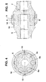
- a recess 11 is provided, which forms a continuous space for the split ring 9 in the inserted state of the first and second male part 5, 7, as in Figs. 4 and 5 in a planar section clearly see is.
- Figs. 3 and 8 The fixation and securing of the male parts 5 and 7 and the split ring 9 is shown in Figs. 3 and 8 (in Fig. 4 in the planar section to see) by a over the split ring 9 lying ring band 16 and partly in the ring band 16 and partly in the split ring 9 inserted pins with screw 15 guaranteed.
- the position of a hand lever 17 is fixed by a locking pin 25.
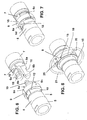
- FIGS. 6 to 8 deviates from the number of arms 6a, 6b (two arms) and a freely projecting mandrel 19 in the first male part 5, which is inserted centering in a core bore 14 of the second male part 7.
- the embodiments of Figs. 1 to 3 and Figs. 6 to 8 are equivalent in principle.
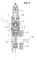
- Fig. 9 the initially mentioned application of the coupling is shown on the support roller stands of a continuous casting apparatus.
- a connection of the segment frame 23 of the fixed side and the segment frame 24 of the loose side of the support roller frame is made in each case by means of handlebars 22.
Landscapes
- Engineering & Computer Science (AREA)
- General Engineering & Computer Science (AREA)
- Mechanical Engineering (AREA)
- Molds, Cores, And Manufacturing Methods Thereof (AREA)
- Pistons, Piston Rings, And Cylinders (AREA)
- Actuator (AREA)
- Details Of Connecting Devices For Male And Female Coupling (AREA)
- Infusion, Injection, And Reservoir Apparatuses (AREA)
- Pens And Brushes (AREA)
Abstract
Description
- Die Erfindung betrifft eine Kupplung aus zwei verstellbaren Steckteilen für antriebsmäßig zu verbindende oder zu lösende, koaxial verlaufende Antriebselemente einer Stranggießvorrichtung für flüssige Metalle, insbesondere für flüssige Stahlwerkstoffe.
- In den bezeichneten Stranggießmaschinen befindet sich eine Anzahl von Antrieben, die in heißen Zonen der Anlage, wie bspw. in der Nähe der Stranggießkokille arbeiten und zur Wartung, in Betriebsfällen und bei Schäden schnell ausgebaut und wieder eingebaut werden müssen. Verbindungen zwischen einer Antriebsstange und einer Abtriebsstange müssen ohne Hemmnisse, die durch die Hitze und Verschmutzung entstehen, gelöst und wieder verbunden werden. Wie sich gezeigt hat, sind handelsübliche Kupplungen nicht geeignet, diese Bedingungen zu erfüllen. In Fällen, in denen Axialkräfte mittels verschraubter Flansche oder mittels Gelenkkopf von der Antriebsstange auf die Abtriebsstange übertragen werden, ist erforderlich, im heißen Stranggießbetrieb zum Lösen der Antriebsstange von der Abtriebsstange Schraubverbindungen bzw. den Gelenkkopf zu lösen.
- Eine solche Anwendungsstelle der Erfindung bei entsprechender Gestaltung der beiden axial verstellbaren Kupplungsteile ist in der
DE-OS 26 53 126 beschrieben. - Dort sind zwei mit gleichen Verzahnungen versehene Steckteile zum Verstellen einer Schmalseitenwand einer Stranggießkokille auf konzentrischen Antriebswellen vorgesehen. Auf der beweglichen Seite ist eine Kupplungshälfte an einem Hubring gelenkig befestigt und der Hubring wird mittels einer Hubspindel betätigt, wobei diese Kupplungshälfte bewegt werden kann, währenddem die andere Kupplungshälfte feststeht. Die Verzahnung der beiden Kupplungshälften ist nicht weiter geschützt und gegenüber Schmutz, Wasser, Dämpfen und Gasen offen. Es ist nicht auszuschließen, dass dadurch eine Beeinträchtigung der Kupplungsbetätigung eintreten kann.
- Der Erfindung liegt die Aufgabe zugrunde, auch bei Anordnung solcher Kupplungen im heißen und schmutzgefährdeten Bereich von Stranggießmaschinen, ein schnelles und sicheres Lösen oder Kuppeln der beiden Kupplungshälften leicht zu ermöglichen, so dass der Einfluss von Schmutz, Wasser, Dämpfen oder Gasen erheblich vermindert werden kann.
- Die gestellte Aufgabe wird erfindungsgemäß dadurch gelöst, dass für eine axiale Verbindung zweier Antriebsabschnitte eines Antriebs für Schmalseitenwände einer Platten-Stranggießkokille der Breiten- und / oder Konizitätsverstellung, oder einer Verbindungswelle eines Spindeltriebs mit Verzweigungsgetriebe, oder von Gelenkköpfen eines hydraulischen Kolben-Zylinder-Antriebs ein erster Steckteil mit sternförmigen Auslegern und ein zweiter Steckteil mit korrespondierenden passenden Ausnehmungen versehen ist, dass auf dem ersten Steckteil ein radial drehbarer zweiteiliger Ring und an dem zweiten Steckteil eine ringförmige Nut ausgebildet ist und dass der zweiteilige Ring in gekuppelter Position die Steckteile über Formschluss verdrehsicher fixiert. Dadurch können beide Steckteile trotz Schmutz, Wasser, Gasen oder Dämpfen auf lange Zeit funktionssicher gehalten werden und die Verriegelung kann schnell geschlossen oder geöffnet werden. Der Zutritt von Schmutz, Wasser, Gasen oder Dämpfen wird weitgehend verhindert und die Kupplungsstelle an der entscheidenden Stelle von außen nach innen verlegt. Die schädlichen Stoffe können sehr viel schwieriger nach innen dringen und selbst bei Ablagerungen werden diese Stoffe nicht an den Kupplungsflächen abgelagert. Ein wesentlicher Vorteil liegt in der schnellen und sicheren Ver- oder Entriegelung der Kupplung beim Verbinden oder Lösen einer Antriebseinheit in Stranggießmaschinen. Hierdurch wird eine Reduzierung der Wechselzeiten von Baugruppen in der Stranggießvorrich-tung erreicht.
- Eine sehr kurze Betätigungszeit kann nach einer Ausgestaltung dadurch erzielt werden, dass der zweiteilige Ring in sich gegenüberliegenden Ausdrehungen durch eine Umdrehung von 30° bis 90° die Verdrehsicherung bildet.
- Die Länge der für die Sicherung notwendigen Drehbewegung wird nach einer anderen Ausgestaltung dadurch erzielt, dass der Verdrehwinkel des zweiteiligen Ringes mittels beidseitig am Ende des Drehweges angeordnete Stifte begrenzt ist.
- Eine andere Verbesserung besteht darin, dass der geteilte Ring bei ineinandergesteckten Steckteilen in der Nut des ersten Steckteils und in der Ausdrehung des zweiten Steckteils hälftig eingefügt und in der verriegelten Position mittels eines Stiftes mit Schraube fixiert ist. Dadurch kann die Betriebsstellung schnell und zuverlässig festgelegt oder gelöst und dauerhaft erhalten werden.
- Das Lösen oder Verriegeln des zweiteiligen Ringes kann nach einer anderen Fortbildung dadurch leichter gehandhabt werden, indem auf den zweiteiligen Ring ein Ringband axial über den Schaft aufschiebbar ist, durch das ein Arretierstift in eine Bohrung des jeweiligen backenförmigen Auslegers in der Verriegelungsposition geführt ist.
- Dabei dient zur leichteren Handhabung, dass ein Handhebel oder ein radial mittels Streben beabstandetes Handrad vorgesehen ist, wobei der Arretierstift durch das Ringband verlaufend im Verriegelungszustand jeweils in einen backenförmigen Ausleger eingreift.
- In der Zeichnung sind Ausführungsbeispiele der Erfindung dargestellt, die nachstehend näher beschrieben werden.
- Es zeigen:
- Figur 1
- eine perspektivische Ansicht der beiden Steckteile in Explosiv-Darstellung
- Figur 1A
- eine Einzelheit eines geteilten Ringes zur Verbindung der beiden Steckteile,
- Figur 2
- eine perspektivische Ansicht der Steckteile während des Steck- und des Verriegelungsvorgangs,
- Figur 3
- ebenfalls perspektivisch die beiden Steckteile in verriegelter Position,
- Figur 4
- stellt einen ebenen radialen Schnitt A-B gemäß Fig. 5 dar, wobei in
- Figur 5
- der axiale Schnitt gezeigt ist,
- Figur 6
- zeigt perspektivisch ein zweites Ausführungsbeispiel mit einem zentrischen Dorn und nur zwei Auslegern des ersten Steckteils und entsprechenden Ausnehmungen im zweiten Steckteil,
- Figur 7
- zeigt perspektivisch den Fig. 2 entsprechenden Steckzustand der beiden Steckteile,
- Figur 8
- zeigt perspektivisch den Fig. 3 entsprechenden zusammengebauten und fixierten Zustand und
- Figur 9
- einen senkrechten Schnitt durch eine Seite eines Segmentrahmens einer Stranggießvorrichtung.
- Die gezeigte Kupplung wird in Stranggießvorrichtungen 1 für eine axiale Verbindung zweier Antriebsabschnitte 2, bspw. für Schmalseitenwände einer Platten-Stranggieß-kokille der Breiten- und / oder Konizitätsverstellung oder an einer Verbindungswelle eines Spindeltriebs mit Verzweigungsgetriebe oder, wie in Fig. 9 gezeigt ist, an Gelenkköpfen 3 eines hydraulischen Kolben-Zylinder-Antriebs 4 eingesetzt. Die Kupplung überträgt nur axiale Kräfte und ist nicht für Torsionskräfte vorgesehen.
- In Fig. 1 ist von der Kupplung ein erster Steckteil 5 (links) in zerlegter Darstellung vor einem zweiten Steckteil 7 (rechts) gezeigt. Der erste Steckteil 5 besitzt eine Gruppe von sternförmigen Auslegern 6, von denen zwei, drei, vier, fünf oder mehr Ausleger 6a, 6b, 6c usw. gezeigt sind. Im Ausführungsbeispiel sind sechs Ausleger 6 ausgeführt. Der zweite Steckteil 7 besitzt zu den Auslegern 6a, 6b, 6c ... korrespondierende Ausnehmungen 8a, 8b ... 8e am Außenumfang des Absatzes eines Schaftes und so dass die Ausleger 6 bei Heranfahren in die korrespondierenden Ausnehmungen 8a, 8b, ... ineinandergleiten können. In dem verlängerten Schaft des ersten Steckteils 5 ist für einen zweiteiligen Ring 9 eine Nut 10 vorgesehen, der für sich in Fig. 1A gezeigt ist. In dem Schaft des zweiten Steckteils 7 ist eine Ausdrehung 11 vorgesehen, die im gesteckten Zustand des ersten und des zweiten Steckteils 5, 7 einen durchgehenden Raum für den zweigeteilten Ring 9 bildet, wie in den Fig. 4 und 5 in einem ebenen Schnitt deutlich zu sehen ist.
- In Fig. 2 werden die Steckteile 5, 7 vollends ineinandergesteckt, so dass die vorderen Enden der sternförmigen Ausleger 6 an das Ende der korrespondierenden Ausnehmungen 8a, 8b, 8c ... anliegen. Nach der Montage des zweiteiligen Ringes 9 und nach dessen Verdrehen um 30° bis 90° ist der Zustand erreicht, dass der Stift 12 am Ende einer Aussparung 12a anschlägt, wodurch auch das in die Nute 10 passende Gegenstück 13, vgl. Fig. 4, in die Verriegelungslage gelangt. Der Zusammenbau und die Verriegelung sind wie zu den Fig. 1 bis 3 beschrieben übereinstimmend mit der Ausführungsform der Fig. 6 und 7.
- Die Fixierung und die Sicherung der Steckteile 5 und 7 und des geteilten Ringes 9 wird gemäß den Fig. 3 und 8 (in Fig. 4 in dem ebenen Schnitt zu sehen) durch ein über dem geteilten Ring 9 liegendes Ringband 16 und teils in dem Ringband 16 und teils in dem geteilten Ring 9 gesteckten Stiften mit Schraube 15 gewährleistet. Die Lage eines Handhebels 17 wird durch einen Arretierstift 25 fixiert.
- Die Ausführungsform der Fig. 6 bis 8 weicht durch die Anzahl der Ausleger 6a, 6b (zwei Ausleger) und einen frei vorstehenden Dorn 19 im ersten Steckteil 5 ab, der in eine Kernbohrung 14 des zweiten Steckteils 7 zentrierend eingeführt wird. Die Ausführungsformen der Fig. 1 bis 3 und der Fig. 6 bis 8 sind im Prinzip gleichwertig.
- Gemäß den Fig. 3 und 8 werden die Handhabung und die Betätigung im Betrieb dadurch erleichtert, dass auf den zweiteiligen Ring 9 das Ringband 16 axial über den Schaft aufgeschoben wird, durch das die Stifte 15 in Bohrungen 18 der backenartigen Ausleger 6a, 6b (6c ...) in der Verriegelungs-Position hineinragen. Ferner ist der an dem Ringband 16 angreifende, radial verlaufende Handhebel 17 vorgesehen oder ein mittels Streben 20 beabstandetes Handrad 21 vergrößerten Durchmessers. Das Ringband 16 ist auch hier mittels des Arretierstiftes 25 fixiert.
- In Fig. 9 ist die eingangs erwähnte Anwendung der Kupplung an den Stützrollengerüsten einer Stranggießvorrichtung gezeigt. Dabei ist eine Verbindung der Segmentrahmen 23 der Festseite und der Segmentrahmen 24 der Losseite des Stützrollengerüstes jeweils mittels Lenkerstangen 22 vorgenommen. Das Gelenk zwischen einem hydraulischen Kolben-Zylinder-Antrieb 4, d.h. dessen Kolbenstange 4a erfolgt über die beschriebene Kupplung, die aus dem ersten Steckteil 5 und dem zweiten Steckteil 7 gebildet ist, wie beschrieben. Dadurch ist diese Verbindung leicht und schnell lösbar.
- Bezugszeichenliste
- 1
- Stranggießvorrichtung
- 2
- Antriebsabschnitt
- 3
- Gelenkkopf
- 4
- hydraulischer Kolben-Zylinder-Antrieb
- 4a
- Kolbenstange
- 5
- erster Steckteil
- 6
- sternförmiger Ausleger
- 6a
- Ausleger
- 6b
- Ausleger
- 6c
- Ausleger
- 7
- zweiter Steckteil
- 8a
- korrespondierende Ausnehmung
- 8b
- korrespondierende Ausnehmung
- 8c
- korrespondierende Ausnehmung
- 8d
- korrespondierende Ausnehmung
- 8e
- korrespondierende Ausnehmung
- 9
- zweiteiliger Ring
- 10
- Nute
- 11
- Ausdrehung im zweiten Steckteil (7)
- 12
- am Ende des Drehwegs angeordneter Stift
- 12a
- Aussparung
- 13
- in Nute (10) passendes Gegenstück
- 14
- Kernbohrung
- 15
- Stift mit Schraube
- 16
- Ringband
- 17
- Handhebel
- 18
- Bohrung
- 19
- frei vorstehender Dorn
- 20
- Strebe
- 21
- Handrad
- 22
- Lenkerstange
- 23
- Segmentrahmen, Festseite
- 24
- Segmentrahmen, Losseite
- 25
- Arretierstift
Claims (7)
- Kupplung aus zwei verstellbaren Steckteilen (5; 7) für antriebsmäßig zu verbindende oder zu lösende, koaxial verlaufende Antriebsabschnitte (2) einer Stranggießvorrichtung (1) für flüssige Metalle, insbesondere für flüssige Stahlwerkstoffe,
dadurch gekennzeichnet,
dass für eine axiale Verbindung zweier Antriebsabschnitte (2) eines Antriebs für Schmalseitenwände einer Platten-Stranggießkokille der Breiten- und / oder Konizitätsverstellung, oder einer Verbindungswelle eines Spindeltriebs mit Verzweigungsgetriebe, oder von Gelenkköpfen (3) eines hydraulischen Kolben-Zylinder-Antriebs (4) ein erster Steckteil (5) mit sternförmigen Auslegern (6) und ein zweiter Steckteil (7) mit korrespondierend passenden Ausnehmungen (8a, 8b, 8c usw.) versehen ist, dass auf dem ersten Steckteil (5) ein radial drehbarer zweiteiliger Ring (9) und an dem zweiten Steckteil (7) eine ringförmige Nut (10) ausgebildet ist und dass der zweiteilige Ring (9) in gekuppelter Position die Steckteile (5; 7) über Formschluss verdrehsicher fixiert. - Kupplung nach Anspruch 1,
dadurch gekennzeichnet,
dass der zweiteilige Ring (9) in sich gegenüberliegenden Ausdrehungen (10; 11) durch eine Umdrehung von 30° bis 90° die Verdrehsicherung bildet. - Kupplung nach den Ansprüchen 1 und 2,
dadurch gekennzeichnet,
dass der Verdrehwinkel des zweiteiligen Rings (9) mittels beidseitig am Ende des Drehweges angeordnete Stifte (12) begrenzt ist. - Kupplung nach einem der Ansprüche 1 bis 3,
dadurch gekennzeichnet,
dass der geteilte Ring (9) bei ineinandergesteckten Steckteilen (5 und 7) in der Nut (10) des ersten Steckteils (5) und in der Ausdrehung (11) des zweiten Steckteils (7) hälftig eingefügt und in der verriegelten Position mittels eines Stiftes mit Schraube (15) fixiert ist. - Kupplung nach einem der Ansprüche 1 bis 4,
dadurch gekennzeichnet,
dass auf den zweiteiligen Ring (9) ein Ringband (16) axial über den Schaft aufschiebbar ist, durch das ein Arretierstift (25) in eine Bohrung (18) des jeweiligen backenförmigen Auslegers (6a; 6b; 6c ...) in der Verriegelungsposition geführt ist. - Kupplung nach Anspruch 5,
dadurch gekennzeichnet,
dass ein Handhebel (17) oder ein radial mittels Streben (20) beabstandetes Handrad (21) vorgesehen ist, wobei der Arretierstift (25) durch das Ringband (16) verlaufend im Verriegelungszustand jeweils in einen backenförmigen Ausleger (6a; 6b; 6c ...) eingreift. - Kupplung nach Anspruch 1,
dadurch gekennzeichnet,
dass der erste Steckteil (5) mittels eines frei vorstehenden Dornes (19) in einer Kernbohrung (14) des zweiten Steckteils (7) zum Einführen zentriert ist.
Applications Claiming Priority (1)
| Application Number | Priority Date | Filing Date | Title |
|---|---|---|---|
| DE102005012790A DE102005012790A1 (de) | 2005-03-19 | 2005-03-19 | Kupplung aus zwei verstellbaren Steckteilen |
Publications (2)
| Publication Number | Publication Date |
|---|---|
| EP1703156A1 true EP1703156A1 (de) | 2006-09-20 |
| EP1703156B1 EP1703156B1 (de) | 2008-07-16 |
Family
ID=36579816
Family Applications (1)
| Application Number | Title | Priority Date | Filing Date |
|---|---|---|---|
| EP06005471A Expired - Lifetime EP1703156B1 (de) | 2005-03-19 | 2006-03-17 | Kupplung aus zwei verstellbaren Steckteilen |
Country Status (3)
| Country | Link |
|---|---|
| EP (1) | EP1703156B1 (de) |
| AT (1) | ATE401510T1 (de) |
| DE (2) | DE102005012790A1 (de) |
Cited By (5)
| Publication number | Priority date | Publication date | Assignee | Title |
|---|---|---|---|---|
| CN102594091A (zh) * | 2011-01-05 | 2012-07-18 | 鸿富锦精密工业(深圳)有限公司 | 轴传动机构 |
| US20190009416A1 (en) * | 2015-02-16 | 2019-01-10 | Norgren Automation Solutions, Llc | Quick Disconnect Apparatus for Modular Tooling |
| US10487880B2 (en) * | 2016-08-24 | 2019-11-26 | Brian Stack | Split drive train |
| IT201800010773A1 (it) | 2018-12-05 | 2020-06-05 | Roberto Sanavia | Dispositivo per il bloccaggio mobile di una tubazione idraulica ad un collettore |
| CN118728931A (zh) * | 2024-09-02 | 2024-10-01 | 南通博益精密机械制造有限公司 | 一种收割机变速箱输出轴机构 |
Families Citing this family (1)
| Publication number | Priority date | Publication date | Assignee | Title |
|---|---|---|---|---|
| DE102009041491B4 (de) * | 2009-09-10 | 2013-04-11 | Keiper Gmbh & Co. Kg | Beschlag für einen Fahrzeugsitz und Fahrzeugsitz |
Citations (5)
| Publication number | Priority date | Publication date | Assignee | Title |
|---|---|---|---|---|
| US3606407A (en) * | 1970-04-07 | 1971-09-20 | Lawrence Pendergast | Break-away shaft |
| DE2653126A1 (de) | 1975-11-24 | 1977-06-02 | Voest Ag | Plattenkokille zum stranggiessen von stahlbrammen |
| DE3042260A1 (de) * | 1980-11-08 | 1982-06-16 | Sack GmbH, 4000 Düsseldorf | Verstellbare stranggiesskokille |
| WO2002101255A1 (en) * | 2001-06-11 | 2002-12-19 | Aktiebolaget Somas Ventiler | Coupling device, preferably between an actuator and a valve |
| EP1486273A1 (de) * | 2003-06-14 | 2004-12-15 | SMS Demag Aktiengesellschaft | Stranggiesskokille mit Verstellorganen für mehrere Kupferplatten, die den Giesshohlraum umschliessen |
-
2005
- 2005-03-19 DE DE102005012790A patent/DE102005012790A1/de not_active Withdrawn
-
2006
- 2006-03-17 EP EP06005471A patent/EP1703156B1/de not_active Expired - Lifetime
- 2006-03-17 DE DE502006001092T patent/DE502006001092D1/de not_active Expired - Lifetime
- 2006-03-17 AT AT06005471T patent/ATE401510T1/de active
Patent Citations (5)
| Publication number | Priority date | Publication date | Assignee | Title |
|---|---|---|---|---|
| US3606407A (en) * | 1970-04-07 | 1971-09-20 | Lawrence Pendergast | Break-away shaft |
| DE2653126A1 (de) | 1975-11-24 | 1977-06-02 | Voest Ag | Plattenkokille zum stranggiessen von stahlbrammen |
| DE3042260A1 (de) * | 1980-11-08 | 1982-06-16 | Sack GmbH, 4000 Düsseldorf | Verstellbare stranggiesskokille |
| WO2002101255A1 (en) * | 2001-06-11 | 2002-12-19 | Aktiebolaget Somas Ventiler | Coupling device, preferably between an actuator and a valve |
| EP1486273A1 (de) * | 2003-06-14 | 2004-12-15 | SMS Demag Aktiengesellschaft | Stranggiesskokille mit Verstellorganen für mehrere Kupferplatten, die den Giesshohlraum umschliessen |
Cited By (6)
| Publication number | Priority date | Publication date | Assignee | Title |
|---|---|---|---|---|
| CN102594091A (zh) * | 2011-01-05 | 2012-07-18 | 鸿富锦精密工业(深圳)有限公司 | 轴传动机构 |
| US20190009416A1 (en) * | 2015-02-16 | 2019-01-10 | Norgren Automation Solutions, Llc | Quick Disconnect Apparatus for Modular Tooling |
| US10836050B2 (en) * | 2015-02-16 | 2020-11-17 | Norgren Automation Solutions, Llc | Quick disconnect apparatus for modular tooling |
| US10487880B2 (en) * | 2016-08-24 | 2019-11-26 | Brian Stack | Split drive train |
| IT201800010773A1 (it) | 2018-12-05 | 2020-06-05 | Roberto Sanavia | Dispositivo per il bloccaggio mobile di una tubazione idraulica ad un collettore |
| CN118728931A (zh) * | 2024-09-02 | 2024-10-01 | 南通博益精密机械制造有限公司 | 一种收割机变速箱输出轴机构 |
Also Published As
| Publication number | Publication date |
|---|---|
| EP1703156B1 (de) | 2008-07-16 |
| ATE401510T1 (de) | 2008-08-15 |
| DE502006001092D1 (de) | 2008-08-28 |
| DE102005012790A1 (de) | 2006-09-21 |
Similar Documents
| Publication | Publication Date | Title |
|---|---|---|
| DE69804941T2 (de) | Klemmbackeneinheit für kraftzangen | |
| DE69427925T2 (de) | Notauslösbare kupplung mit leckagefrei trennbaren doppelkugelventilen | |
| DE2241454C3 (de) | Verbindungseinrichtung zwischen einem Flugzeugmotor und Hilfsgeräten des Flugzeuges | |
| EP3794266B1 (de) | Fluidkupplung | |
| DE20107206U1 (de) | Antriebsvorrichtung für eine Greifeinrichtung | |
| DE60312195T2 (de) | Schnellkopplungs- und schnell -sicherheitsverbinder für rohrleitungen | |
| DE2826596C2 (de) | Stopfrohranordnung an einer Wurstfüllmaschine | |
| EP0137961B2 (de) | Ausziehvorrichtung für einen Gasspülstein | |
| EP1703156B1 (de) | Kupplung aus zwei verstellbaren Steckteilen | |
| DE19503682C1 (de) | Schnellwechselvorrichtung für Walzscheiben | |
| EP3325834B1 (de) | Anordnung zur drehverbindung einer belastungsmaschine eines prüfstandes mit einem prüfling | |
| DE3605615A1 (de) | Wellenzapfen mit bajonettverschluss, insbesondere zum festlegen des innenzylinders einer hydraulischen abziehvorrichtung fuer walzenlager auf dem walzenzapfen | |
| EP0484315A2 (de) | Spritzwerkzeug | |
| EP3239076B1 (de) | Fördereinheit | |
| EP0251091A2 (de) | Vollschlauchsystemkupplung | |
| DE202009018738U1 (de) | Leicht lösbares Kupplungssystem zur axialen Kupplung von zwei Flanschen | |
| EP0713023B1 (de) | Wellenkupplung | |
| DE3207519A1 (de) | Kupplungseinrichtung | |
| EP1530694A1 (de) | Geteilte mitnehmeranordnung für eine gleitringdichtung | |
| DE102007026985A1 (de) | Vorrichtung zum automatischen Ankuppeln eines Gießlöffels | |
| DE4137921A1 (de) | Vorrichtung zum kuppeln eines wickelwellenzapfens mit einem antriebswellenzapfen | |
| DE1288372B (de) | Homokinetische Kreuzgelenkkupplung | |
| DE3402444A1 (de) | Ausziehvorrichtung fuer einen gasspuelstein | |
| DE3723910C1 (de) | Vorrichtung zum Verbinden einer Huelse mit einer Nabe | |
| DE4112163C2 (de) | Vorrichtung zur lösbaren Verbindung von Greiferschienenteilen in einer Transferpresse |
Legal Events
| Date | Code | Title | Description |
|---|---|---|---|
| PUAI | Public reference made under article 153(3) epc to a published international application that has entered the european phase |
Free format text: ORIGINAL CODE: 0009012 |
|
| 17P | Request for examination filed |
Effective date: 20060317 |
|
| AK | Designated contracting states |
Kind code of ref document: A1 Designated state(s): AT BE BG CH CY CZ DE DK EE ES FI FR GB GR HU IE IS IT LI LT LU LV MC NL PL PT RO SE SI SK TR |
|
| AX | Request for extension of the european patent |
Extension state: AL BA HR MK YU |
|
| AKX | Designation fees paid |
Designated state(s): AT BE BG CH CY CZ DE DK EE ES FI FR GB GR HU IE IS IT LI LT LU LV MC NL PL PT RO SE SI SK TR |
|
| GRAP | Despatch of communication of intention to grant a patent |
Free format text: ORIGINAL CODE: EPIDOSNIGR1 |
|
| GRAS | Grant fee paid |
Free format text: ORIGINAL CODE: EPIDOSNIGR3 |
|
| GRAA | (expected) grant |
Free format text: ORIGINAL CODE: 0009210 |
|
| AK | Designated contracting states |
Kind code of ref document: B1 Designated state(s): AT BE BG CH CY CZ DE DK EE ES FI FR GB GR HU IE IS IT LI LT LU LV MC NL PL PT RO SE SI SK TR |
|
| REG | Reference to a national code |
Ref country code: GB Ref legal event code: FG4D Free format text: NOT ENGLISH |
|
| REG | Reference to a national code |
Ref country code: CH Ref legal event code: EP |
|
| REF | Corresponds to: |
Ref document number: 502006001092 Country of ref document: DE Date of ref document: 20080828 Kind code of ref document: P |
|
| REG | Reference to a national code |
Ref country code: IE Ref legal event code: FG4D Free format text: LANGUAGE OF EP DOCUMENT: GERMAN |
|
| NLV1 | Nl: lapsed or annulled due to failure to fulfill the requirements of art. 29p and 29m of the patents act | ||
| PG25 | Lapsed in a contracting state [announced via postgrant information from national office to epo] |
Ref country code: IS Free format text: LAPSE BECAUSE OF FAILURE TO SUBMIT A TRANSLATION OF THE DESCRIPTION OR TO PAY THE FEE WITHIN THE PRESCRIBED TIME-LIMIT Effective date: 20081116 Ref country code: NL Free format text: LAPSE BECAUSE OF FAILURE TO SUBMIT A TRANSLATION OF THE DESCRIPTION OR TO PAY THE FEE WITHIN THE PRESCRIBED TIME-LIMIT Effective date: 20080716 Ref country code: LT Free format text: LAPSE BECAUSE OF FAILURE TO SUBMIT A TRANSLATION OF THE DESCRIPTION OR TO PAY THE FEE WITHIN THE PRESCRIBED TIME-LIMIT Effective date: 20080716 |
|
| PG25 | Lapsed in a contracting state [announced via postgrant information from national office to epo] |
Ref country code: FI Free format text: LAPSE BECAUSE OF FAILURE TO SUBMIT A TRANSLATION OF THE DESCRIPTION OR TO PAY THE FEE WITHIN THE PRESCRIBED TIME-LIMIT Effective date: 20080716 Ref country code: ES Free format text: LAPSE BECAUSE OF FAILURE TO SUBMIT A TRANSLATION OF THE DESCRIPTION OR TO PAY THE FEE WITHIN THE PRESCRIBED TIME-LIMIT Effective date: 20081027 Ref country code: SI Free format text: LAPSE BECAUSE OF FAILURE TO SUBMIT A TRANSLATION OF THE DESCRIPTION OR TO PAY THE FEE WITHIN THE PRESCRIBED TIME-LIMIT Effective date: 20080716 Ref country code: LV Free format text: LAPSE BECAUSE OF FAILURE TO SUBMIT A TRANSLATION OF THE DESCRIPTION OR TO PAY THE FEE WITHIN THE PRESCRIBED TIME-LIMIT Effective date: 20080716 Ref country code: PT Free format text: LAPSE BECAUSE OF FAILURE TO SUBMIT A TRANSLATION OF THE DESCRIPTION OR TO PAY THE FEE WITHIN THE PRESCRIBED TIME-LIMIT Effective date: 20081216 Ref country code: BG Free format text: LAPSE BECAUSE OF FAILURE TO SUBMIT A TRANSLATION OF THE DESCRIPTION OR TO PAY THE FEE WITHIN THE PRESCRIBED TIME-LIMIT Effective date: 20081016 |
|
| REG | Reference to a national code |
Ref country code: IE Ref legal event code: FD4D |
|
| PG25 | Lapsed in a contracting state [announced via postgrant information from national office to epo] |
Ref country code: EE Free format text: LAPSE BECAUSE OF FAILURE TO SUBMIT A TRANSLATION OF THE DESCRIPTION OR TO PAY THE FEE WITHIN THE PRESCRIBED TIME-LIMIT Effective date: 20080716 Ref country code: IE Free format text: LAPSE BECAUSE OF FAILURE TO SUBMIT A TRANSLATION OF THE DESCRIPTION OR TO PAY THE FEE WITHIN THE PRESCRIBED TIME-LIMIT Effective date: 20080716 Ref country code: DK Free format text: LAPSE BECAUSE OF FAILURE TO SUBMIT A TRANSLATION OF THE DESCRIPTION OR TO PAY THE FEE WITHIN THE PRESCRIBED TIME-LIMIT Effective date: 20080716 |
|
| PLBE | No opposition filed within time limit |
Free format text: ORIGINAL CODE: 0009261 |
|
| STAA | Information on the status of an ep patent application or granted ep patent |
Free format text: STATUS: NO OPPOSITION FILED WITHIN TIME LIMIT |
|
| PG25 | Lapsed in a contracting state [announced via postgrant information from national office to epo] |
Ref country code: RO Free format text: LAPSE BECAUSE OF FAILURE TO SUBMIT A TRANSLATION OF THE DESCRIPTION OR TO PAY THE FEE WITHIN THE PRESCRIBED TIME-LIMIT Effective date: 20080716 Ref country code: SK Free format text: LAPSE BECAUSE OF FAILURE TO SUBMIT A TRANSLATION OF THE DESCRIPTION OR TO PAY THE FEE WITHIN THE PRESCRIBED TIME-LIMIT Effective date: 20080716 Ref country code: CZ Free format text: LAPSE BECAUSE OF FAILURE TO SUBMIT A TRANSLATION OF THE DESCRIPTION OR TO PAY THE FEE WITHIN THE PRESCRIBED TIME-LIMIT Effective date: 20080716 |
|
| RAP2 | Party data changed (patent owner data changed or rights of a patent transferred) |
Owner name: SMS SIEMAG AG |
|
| 26N | No opposition filed |
Effective date: 20090417 |
|
| BERE | Be: lapsed |
Owner name: SMS DEMAG AG Effective date: 20090331 |
|
| PG25 | Lapsed in a contracting state [announced via postgrant information from national office to epo] |
Ref country code: MC Free format text: LAPSE BECAUSE OF NON-PAYMENT OF DUE FEES Effective date: 20090331 |
|
| REG | Reference to a national code |
Ref country code: FR Ref legal event code: ST Effective date: 20091130 |
|
| PG25 | Lapsed in a contracting state [announced via postgrant information from national office to epo] |
Ref country code: SE Free format text: LAPSE BECAUSE OF FAILURE TO SUBMIT A TRANSLATION OF THE DESCRIPTION OR TO PAY THE FEE WITHIN THE PRESCRIBED TIME-LIMIT Effective date: 20081016 |
|
| PG25 | Lapsed in a contracting state [announced via postgrant information from national office to epo] |
Ref country code: BE Free format text: LAPSE BECAUSE OF NON-PAYMENT OF DUE FEES Effective date: 20090331 |
|
| PG25 | Lapsed in a contracting state [announced via postgrant information from national office to epo] |
Ref country code: FR Free format text: LAPSE BECAUSE OF NON-PAYMENT OF DUE FEES Effective date: 20091123 |
|
| PG25 | Lapsed in a contracting state [announced via postgrant information from national office to epo] |
Ref country code: PL Free format text: LAPSE BECAUSE OF FAILURE TO SUBMIT A TRANSLATION OF THE DESCRIPTION OR TO PAY THE FEE WITHIN THE PRESCRIBED TIME-LIMIT Effective date: 20080716 |
|
| PG25 | Lapsed in a contracting state [announced via postgrant information from national office to epo] |
Ref country code: GR Free format text: LAPSE BECAUSE OF FAILURE TO SUBMIT A TRANSLATION OF THE DESCRIPTION OR TO PAY THE FEE WITHIN THE PRESCRIBED TIME-LIMIT Effective date: 20081017 |
|
| REG | Reference to a national code |
Ref country code: CH Ref legal event code: PL |
|
| PG25 | Lapsed in a contracting state [announced via postgrant information from national office to epo] |
Ref country code: LI Free format text: LAPSE BECAUSE OF NON-PAYMENT OF DUE FEES Effective date: 20100331 Ref country code: CH Free format text: LAPSE BECAUSE OF NON-PAYMENT OF DUE FEES Effective date: 20100331 |
|
| PG25 | Lapsed in a contracting state [announced via postgrant information from national office to epo] |
Ref country code: LU Free format text: LAPSE BECAUSE OF NON-PAYMENT OF DUE FEES Effective date: 20090317 |
|
| PG25 | Lapsed in a contracting state [announced via postgrant information from national office to epo] |
Ref country code: HU Free format text: LAPSE BECAUSE OF FAILURE TO SUBMIT A TRANSLATION OF THE DESCRIPTION OR TO PAY THE FEE WITHIN THE PRESCRIBED TIME-LIMIT Effective date: 20090117 |
|
| PG25 | Lapsed in a contracting state [announced via postgrant information from national office to epo] |
Ref country code: TR Free format text: LAPSE BECAUSE OF FAILURE TO SUBMIT A TRANSLATION OF THE DESCRIPTION OR TO PAY THE FEE WITHIN THE PRESCRIBED TIME-LIMIT Effective date: 20080716 |
|
| PG25 | Lapsed in a contracting state [announced via postgrant information from national office to epo] |
Ref country code: CY Free format text: LAPSE BECAUSE OF FAILURE TO SUBMIT A TRANSLATION OF THE DESCRIPTION OR TO PAY THE FEE WITHIN THE PRESCRIBED TIME-LIMIT Effective date: 20080716 |
|
| PGFP | Annual fee paid to national office [announced via postgrant information from national office to epo] |
Ref country code: IT Payment date: 20120326 Year of fee payment: 7 |
|
| PGFP | Annual fee paid to national office [announced via postgrant information from national office to epo] |
Ref country code: GB Payment date: 20130321 Year of fee payment: 8 |
|
| PGFP | Annual fee paid to national office [announced via postgrant information from national office to epo] |
Ref country code: AT Payment date: 20130313 Year of fee payment: 8 |
|
| PGFP | Annual fee paid to national office [announced via postgrant information from national office to epo] |
Ref country code: DE Payment date: 20140331 Year of fee payment: 9 |
|
| REG | Reference to a national code |
Ref country code: DE Ref legal event code: R119 Ref document number: 502006001092 Country of ref document: DE |
|
| REG | Reference to a national code |
Ref country code: AT Ref legal event code: MM01 Ref document number: 401510 Country of ref document: AT Kind code of ref document: T Effective date: 20140317 |
|
| GBPC | Gb: european patent ceased through non-payment of renewal fee |
Effective date: 20140317 |
|
| PG25 | Lapsed in a contracting state [announced via postgrant information from national office to epo] |
Ref country code: GB Free format text: LAPSE BECAUSE OF NON-PAYMENT OF DUE FEES Effective date: 20140317 |
|
| REG | Reference to a national code |
Ref country code: DE Ref legal event code: R119 Ref document number: 502006001092 Country of ref document: DE Effective date: 20141001 |
|
| PG25 | Lapsed in a contracting state [announced via postgrant information from national office to epo] |
Ref country code: AT Free format text: LAPSE BECAUSE OF NON-PAYMENT OF DUE FEES Effective date: 20140317 |
|
| PG25 | Lapsed in a contracting state [announced via postgrant information from national office to epo] |
Ref country code: IT Free format text: LAPSE BECAUSE OF NON-PAYMENT OF DUE FEES Effective date: 20140317 |
|
| PG25 | Lapsed in a contracting state [announced via postgrant information from national office to epo] |
Ref country code: DE Free format text: LAPSE BECAUSE OF NON-PAYMENT OF DUE FEES Effective date: 20141001 |