EP3325834B1 - Anordnung zur drehverbindung einer belastungsmaschine eines prüfstandes mit einem prüfling - Google Patents
Anordnung zur drehverbindung einer belastungsmaschine eines prüfstandes mit einem prüfling Download PDFInfo
- Publication number
- EP3325834B1 EP3325834B1 EP16741017.4A EP16741017A EP3325834B1 EP 3325834 B1 EP3325834 B1 EP 3325834B1 EP 16741017 A EP16741017 A EP 16741017A EP 3325834 B1 EP3325834 B1 EP 3325834B1
- Authority
- EP
- European Patent Office
- Prior art keywords
- shaft
- adapter
- connection
- axial
- test object
- Prior art date
- Legal status (The legal status is an assumption and is not a legal conclusion. Google has not performed a legal analysis and makes no representation as to the accuracy of the status listed.)
- Active
Links
- 230000008878 coupling Effects 0.000 claims description 78
- 238000010168 coupling process Methods 0.000 claims description 78
- 238000005859 coupling reaction Methods 0.000 claims description 78
- 230000033001 locomotion Effects 0.000 claims description 14
- 238000003780 insertion Methods 0.000 claims description 13
- 230000037431 insertion Effects 0.000 claims description 13
- 238000000926 separation method Methods 0.000 claims description 3
- 210000000078 claw Anatomy 0.000 description 6
- 230000005540 biological transmission Effects 0.000 description 4
- 238000006243 chemical reaction Methods 0.000 description 3
- 230000006835 compression Effects 0.000 description 3
- 238000007906 compression Methods 0.000 description 3
- 238000013016 damping Methods 0.000 description 3
- 230000000694 effects Effects 0.000 description 2
- 229910000831 Steel Inorganic materials 0.000 description 1
- 230000000712 assembly Effects 0.000 description 1
- 238000000429 assembly Methods 0.000 description 1
- 238000002485 combustion reaction Methods 0.000 description 1
- 238000006073 displacement reaction Methods 0.000 description 1
- 238000000605 extraction Methods 0.000 description 1
- 239000006247 magnetic powder Substances 0.000 description 1
- 230000000704 physical effect Effects 0.000 description 1
- 239000010959 steel Substances 0.000 description 1
- 230000001360 synchronised effect Effects 0.000 description 1
- XLYOFNOQVPJJNP-UHFFFAOYSA-N water Substances O XLYOFNOQVPJJNP-UHFFFAOYSA-N 0.000 description 1
Images


Classifications
-
- F—MECHANICAL ENGINEERING; LIGHTING; HEATING; WEAPONS; BLASTING
- F16—ENGINEERING ELEMENTS AND UNITS; GENERAL MEASURES FOR PRODUCING AND MAINTAINING EFFECTIVE FUNCTIONING OF MACHINES OR INSTALLATIONS; THERMAL INSULATION IN GENERAL
- F16D—COUPLINGS FOR TRANSMITTING ROTATION; CLUTCHES; BRAKES
- F16D1/00—Couplings for rigidly connecting two coaxial shafts or other movable machine elements
- F16D1/10—Quick-acting couplings in which the parts are connected by simply bringing them together axially
- F16D1/108—Quick-acting couplings in which the parts are connected by simply bringing them together axially having retaining means rotating with the coupling and acting by interengaging parts, i.e. positive coupling
- F16D1/112—Quick-acting couplings in which the parts are connected by simply bringing them together axially having retaining means rotating with the coupling and acting by interengaging parts, i.e. positive coupling the interengaging parts comprising torque-transmitting surfaces, e.g. bayonet joints
-
- F—MECHANICAL ENGINEERING; LIGHTING; HEATING; WEAPONS; BLASTING
- F16—ENGINEERING ELEMENTS AND UNITS; GENERAL MEASURES FOR PRODUCING AND MAINTAINING EFFECTIVE FUNCTIONING OF MACHINES OR INSTALLATIONS; THERMAL INSULATION IN GENERAL
- F16D—COUPLINGS FOR TRANSMITTING ROTATION; CLUTCHES; BRAKES
- F16D1/00—Couplings for rigidly connecting two coaxial shafts or other movable machine elements
- F16D1/10—Quick-acting couplings in which the parts are connected by simply bringing them together axially
- F16D1/108—Quick-acting couplings in which the parts are connected by simply bringing them together axially having retaining means rotating with the coupling and acting by interengaging parts, i.e. positive coupling
- F16D1/116—Quick-acting couplings in which the parts are connected by simply bringing them together axially having retaining means rotating with the coupling and acting by interengaging parts, i.e. positive coupling the interengaging parts including a continuous or interrupted circumferential groove in the surface of one of the coupling parts
-
- F—MECHANICAL ENGINEERING; LIGHTING; HEATING; WEAPONS; BLASTING
- F16—ENGINEERING ELEMENTS AND UNITS; GENERAL MEASURES FOR PRODUCING AND MAINTAINING EFFECTIVE FUNCTIONING OF MACHINES OR INSTALLATIONS; THERMAL INSULATION IN GENERAL
- F16D—COUPLINGS FOR TRANSMITTING ROTATION; CLUTCHES; BRAKES
- F16D1/00—Couplings for rigidly connecting two coaxial shafts or other movable machine elements
- F16D1/02—Couplings for rigidly connecting two coaxial shafts or other movable machine elements for connecting two abutting shafts or the like
- F16D1/033—Couplings for rigidly connecting two coaxial shafts or other movable machine elements for connecting two abutting shafts or the like by clamping together two faces perpendicular to the axis of rotation, e.g. with bolted flanges
-
- F—MECHANICAL ENGINEERING; LIGHTING; HEATING; WEAPONS; BLASTING
- F16—ENGINEERING ELEMENTS AND UNITS; GENERAL MEASURES FOR PRODUCING AND MAINTAINING EFFECTIVE FUNCTIONING OF MACHINES OR INSTALLATIONS; THERMAL INSULATION IN GENERAL
- F16D—COUPLINGS FOR TRANSMITTING ROTATION; CLUTCHES; BRAKES
- F16D1/00—Couplings for rigidly connecting two coaxial shafts or other movable machine elements
- F16D1/06—Couplings for rigidly connecting two coaxial shafts or other movable machine elements for attachment of a member on a shaft or on a shaft-end
- F16D1/076—Couplings for rigidly connecting two coaxial shafts or other movable machine elements for attachment of a member on a shaft or on a shaft-end by clamping together two faces perpendicular to the axis of rotation, e.g. with bolted flanges
-
- G—PHYSICS
- G01—MEASURING; TESTING
- G01M—TESTING STATIC OR DYNAMIC BALANCE OF MACHINES OR STRUCTURES; TESTING OF STRUCTURES OR APPARATUS, NOT OTHERWISE PROVIDED FOR
- G01M13/00—Testing of machine parts
- G01M13/02—Gearings; Transmission mechanisms
- G01M13/025—Test-benches with rotational drive means and loading means; Load or drive simulation
-
- G—PHYSICS
- G01—MEASURING; TESTING
- G01M—TESTING STATIC OR DYNAMIC BALANCE OF MACHINES OR STRUCTURES; TESTING OF STRUCTURES OR APPARATUS, NOT OTHERWISE PROVIDED FOR
- G01M15/00—Testing of engines
- G01M15/02—Details or accessories of testing apparatus
-
- F—MECHANICAL ENGINEERING; LIGHTING; HEATING; WEAPONS; BLASTING
- F16—ENGINEERING ELEMENTS AND UNITS; GENERAL MEASURES FOR PRODUCING AND MAINTAINING EFFECTIVE FUNCTIONING OF MACHINES OR INSTALLATIONS; THERMAL INSULATION IN GENERAL
- F16D—COUPLINGS FOR TRANSMITTING ROTATION; CLUTCHES; BRAKES
- F16D1/00—Couplings for rigidly connecting two coaxial shafts or other movable machine elements
- F16D1/10—Quick-acting couplings in which the parts are connected by simply bringing them together axially
- F16D2001/103—Quick-acting couplings in which the parts are connected by simply bringing them together axially the torque is transmitted via splined connections
Definitions
- the invention relates to an arrangement and a device according to the preamble of the independent claims.
- the invention relates to an arrangement for connecting a loading machine of a test stand, in particular an engine test stand or a drive test stand, to a test object.
- Assemblies are designated as loading machines, which for example passive loading machines such as water vortex brakes, eddy current brakes, hysteresis brakes or magnetic powder brakes; active load machines such as direct current machines, asynchronous machines or three-phase synchronous machines, but possibly also torque measuring devices, torque scales, direct current pendulum machines and / or tacho generators as speed measuring devices.
- the device to be tested is generally referred to as the device under test, which device can comprise, for example, a drive device, an internal combustion engine, a drive train and / or a transmission.
- connection arrangements usually comprise a shaft which is connected at its ends via constant velocity joints to a coupling device each, the coupling devices optionally being designed as elastic couplings.
- the coupling devices themselves are usually firmly connected to the load machine of the test bench or the test item via screw connections or flange connections.
- a shaft end connection that can be detached and produced without tools is not disclosed.
- the object of the invention is now to create an arrangement or a device for the rotary connection of the loading machine connection component of a loading machine with the test piece connection component of a test piece which overcomes the disadvantages of the prior art.
- a quick and uncomplicated conversion of the connection components should be made possible.
- the invention comprises an arrangement for the rotary connection of the loading machine connection component of a loading machine of a test stand with the test item connection component of a test item, comprising at least one shaft running along the axis of rotation of the rotary connection, a loading machine coupling device arranged between the shaft and the loading machine connection component of the loading machine for the rotary connection of the shaft to the loading machine connection component, a DUT coupling device provided between the shaft and the test piece connection component of the test piece for the rotary connection of the shaft with the test piece connection component.
- the test piece coupling device comprises at least one test piece adapter connectable to the test piece connection component of a test piece and a shaft adapter connectable or connected to the shaft, the test piece adapter and the shaft adapter comprise positive locking elements for the releasable and positive rotary connection of the test piece adapter with the shaft adapter, and is an axial connection device for the axial connection of the test piece with the shaft adapter provided.
- the axial connection device is designed like a bayonet lock
- the clamping bar is an axial movement by a movement sequence and a rotary movement of the axial connection device can be arranged between the clamping bodies of the axial connection device, and the clamping bodies act as an axial lock against an axial separation of the test specimen adapter from the shaft adapter and as a rotation lock for the axial connection device configured like a bayonet lock.
- the form-fit elements protrude from the mutually facing sides of the shaft adapter and the test piece adapter essentially along the direction of the axis of rotation, i.e. axially, and can be plugged into one another in the axial direction to produce the form-fit rotary connection and can be removed from one another in the axial direction to separate the form-fit rotary connection .
- test specimen adapter and the shaft adapter together form a clamping web when the positive rotary connection is established, which is clamped between clamping bodies of the axial connection device for the axial connection of the test specimen adapter with the shaft adapter.
- test specimen adapter and the shaft adapter have openings running in the axial direction, that the at least one opening of the test specimen adapter is at least partially aligned with the at least one opening of the shaft adapter when the form-locking elements of the test item adapter with the form-locking elements of the shaft adapter for rotary connection in Are engaged, and / or that the axial connection device comprises at least one connection element which protrudes through the openings for the axial connection of the test specimen adapter to the shaft adapter.
- the test specimen adapter and the shaft adapter have openings running in the axial direction, that the openings of the test specimen adapter are at least partially aligned with the openings of the shaft adapter when the positive locking elements of the test specimen adapter are in engagement with the positive locking elements of the shaft adapter for rotary connection
- the axial connection device comprises connecting elements which protrude through the openings for the axial connection of the test specimen adapter with the shaft adapter, that the openings each include an insertion clearance for the axial introduction of the connecting element of the axial connection device and a clamping web clearance for the axial connection of the test specimen adapter to the shaft adapter by actuating the connecting element, wherein the clamping web release runs along a pitch circle around the axis of rotation and is in particular curved in the shape of an elongated hole that the Ver Binding elements each have a shaft with a shaft thickness and two clamping bodies projecting beyond the shaft thickness, so that the clamping web exposure transversely to its course and in particular in the
- the connecting elements each include a screw connection, the shaft of the connecting element being a screw shaft which is inserted into at least one of the two clamping bodies is screwed in or screwed in, and that the distance and the clamping force between the two clamping bodies can be changed by changing the screw-in depth.
- the axial connection device comprises a bayonet ring, via which the connection elements of the axial connection device are connected to one another.
- the form-fit elements of the test piece adapter essentially have a functional negative shape of the form-fit elements of the shaft adapter, the form-fit elements of the test piece adapter and the form-fit elements of the shaft adapter together forming a substantially play-free, positive-fit rotary connection or a substantially play-free, positive-fit rotary connection in both directions of rotation form.
- test object coupling device has a flexible shaft connection, a universal joint or a constant velocity joint for connection to the shaft.
- the invention optionally relates to a system comprising an arrangement in which several shafts with different stiffnesses are provided or provided, which can be used to change the stiffness of the measuring string of the arrangement, optionally for connecting the loading machine coupling device to the test piece coupling device.
- shafts with different stiffnesses are provided or provided, which to change the stiffness of the measuring line of the arrangement optionally for connecting the loading machine coupling device to the Test specimen coupling device can be used, and that the shafts are each connected to a shaft adapter.
- test objects are provided, each of which is connected to a test object adapter, the test objects and their test object adapters optionally being connectable to the loading machine by connecting to the shaft adapter.
- the form-fit elements of all shaft adapters are suitable and set up for the form-fit rotary connection with the form-fit elements of all test object adapters.
- the arrangement or the system comprises a loading machine of a test stand or an engine test stand.
- the invention optionally includes a shaft connection device for the positive rotary connection of a hub to a shaft, the shaft connection device comprising a positive shaft-hub connection, the shaft-hub connection having an axial degree of freedom for inserting a shaft section of the shaft into the hub and for removal of the shaft section of the shaft from the hub, the shaft connection device comprising at least one axial securing element for axially securing the shaft-hub connection, the axial securing element having an extended position in which it protrudes into an axial securing opening, whereby the axial degree of freedom of the shaft-hub -Connection is locked, and wherein the axial locking element has a retracted position in which the axial degree of freedom of the shaft-hub connection is released.
- the actuating device comprises at least one latching lug, at least two latching recesses, a stop body rigidly connected to the hub, and an actuating element that is movable relative to the stop body and can be locked relative to the stop body by inserting the locking lug into one of the latching recess, the actuating device in its The open position is locked when the locking lug is arranged in one of the two associated locking recesses, and wherein the actuating device is locked in its closed position when the locking lug is arranged in the other of the two associated locking recesses.
- the latching lug and the latching recesses run essentially along an axial direction, and that, when the latching lug is inserted into one of the latching recesses, the actuating element and the stop body have an axial degree of freedom relative to one another, but a rotation of the actuating element relative to the stop body is essentially inhibited, in particular inhibited in a form-fitting manner.
- the actuating device for changing between the open position and the closed position has an intermediate position in which the latching lug is arranged outside the latching recesses, that the actuating element has a degree of freedom of rotation in the intermediate position relative to the stop body, and that the latching lug for latching the actuating device in the open position or in the closed position can optionally be introduced or introduced into one of the associated latching recesses.
- the actuating device has an axially acting elastic element, such as in particular a compression spring, the force of which presses the actuating element against the stop body and possibly the locking lug into a locking recess and whose force counteracts a movement of the actuating element from a locked position into the intermediate position.
- an axially acting elastic element such as in particular a compression spring
- the actuating device has at least one control surface for moving the axial securing element from its retracted position into the extended position by moving the actuating device from the open position into the closed position.
- control surface is provided on the actuating element, that the control surface runs obliquely inwards along the axial direction and, in particular, corresponds to the shape of an inner conical ring, and that the axial securing element is in its extended position or in its retracted position, depending on the axial position of the actuating element Position.
- the latching recesses are arranged at a distance from one another along the degree of freedom of rotation of the actuating element, and / or that one latching recess is formed deeper than another latching recess along the axial direction.
- a plurality of axial securing elements are arranged in the radial direction in the hub or each guided in a sliding bushing arranged in the hub and in their extended position project radially inward from the hub and, for axial securing, into an annular groove-shaped axial securing opening provided in the shaft or into several axial securing openings.
- the invention optionally comprises an arrangement for the rotary connection of the loading machine connection component of a loading machine with the test item connection component of a test item, comprising at least one shaft running along the axis of rotation of the rotary connection, a loading machine coupling device arranged between the shaft and the loading machine connection component of the loading machine for the rotary connection of the shaft with the loading machine connection component, one between The test piece coupling device provided for the shaft and the test piece connection component of the test piece for the rotary connection of the shaft with the test piece connection component, wherein the load machine coupling device and / or, if applicable, the test piece coupling device for the positive rotary connection with the shaft comprises a shaft connection device according to the description in question.
- the loading machine coupling device comprises an elastic coupling, or that the loading machine coupling device comprises an elastic coupling arranged along the force flow of the measuring string between the hub and the loading machine connection component of the loading machine.
- the shaft-hub connection is designed as a serration, spline connection or toothed shaft connection.
- the shaft is axially centered in the hub via a fit, in particular a double fit, and in particular that both the shaft journal of the shaft and a shaft shoulder arranged remotely from the shaft journal are centered via a corresponding fit in the area of the hub, or that the shaft is centered on both sides of the shaft-hub connection.
- the test specimen coupling device comprises at least one test specimen adapter connectable or connected to the test specimen connection component of a test specimen and a shaft adapter connectable or connected to the shaft, that the test specimen adapter and the shaft adapter comprise positive locking elements for the detachable and positive rotary connection of the test specimen adapter with the shaft adapter, and that an axial connection device is provided for the axial connection of the test specimen adapter with the shaft adapter.
- the actuating element of the actuating device in all embodiments is designed as an actuating element that can be actuated without tools and in particular as a manually actuable actuating element.
- an arrangement that can be referred to as a system which has at least one shaft, a loading machine coupling device for rotating the shaft with the loading machine connection component of the loading machine and a test piece coupling device for rotating the shaft the test piece connection component of the test piece, the shaft connecting the test piece coupling device and the loading machine coupling device.
- the system or the arrangement preferably comprises several shafts with different stiffness and / or damping properties, which can optionally be used to connect the loading machine coupling device to the test specimen coupling device in order to adapt the elasticity, the resonance parameters or the damping properties of the measuring string of the test stand structure to the respective requirements to be able to.
- the system or the arrangement comprises a plurality of test piece adapters, which can or are each connected to a test piece and which are preferably adapted to the test piece connection component of the test piece.
- all test specimen adapters preferably have the same connection geometry for connection to the shaft adapter (s). All shafts preferably have the same connection geometry for connection to the test specimen coupling device. If necessary, each shaft has its own shaft adapter.
- the elastic coupling is interchangeably or permanently connected to the loading machine connection component of the loading machine.
- the loading machine coupling device comprises a shaft connection device which is designed as a quick-change system.
- a shaft-hub connection is provided which, although it acts positively in the direction of rotation, has an axial degree of freedom for inserting the shaft or for removing the shaft.
- This axial degree of freedom can be blocked by axial locking elements.
- the axial securing elements have an extended position in which they protrude into an axial securing opening in order to block the axial degree of freedom and in particular in order to block the axial degree of freedom in a form-fitting manner.
- an actuating device which has an open position and a closed position.
- the actuating device is optionally designed in such a way that an indicator is provided which shows whether the actuating device, and thus also the shaft connection device, are in their open position or in their closed position.
- the indicator is preferably formed by a locking lug and / or by a locking recess.
- the actuating device can be locked in its open position and in its closed position so that it remains in the respective position without external intervention, in particular until the position is changed through active intervention by an operator.
- an actuating element is provided for actuating the actuating device and for changing the position.
- This actuator has a Control surface which is designed to move the axial securing elements from their retracted position to their extended position or from their extended position to their retracted position when the actuating element is moved. If necessary, only the extension or the retraction is actively brought about by the actuating element, the other movement in each case being brought about by an elastic element, such as a pretensionable or pretensioned spring.
- the actuating element is designed to be ring-shaped and, in particular, to be ring-shaped surrounding the hub.
- the actuating element is preferably guided axially and rotationally, the rotational degree of freedom of the actuating element being blocked when the locking lug is inserted in a locking recess.
- rotation of the actuating element is preferably locked in a form-fitting manner.
- the loading machine coupling device is an elastic coupling which is permanently connected to the loading machine connection component of the test bench and on which the shaft connection device is provided.
- latching lugs are provided along the course of the stop body or the actuating element, two latching recesses preferably being assigned to each latching lug.
- the torque along the measuring string is sequentially transferred from the test item connection component of the test item, the test item adapter, the shaft adapter, possibly a constant velocity joint, the shaft, the shaft-hub connection of the shaft connection device, possibly a flexible coupling and then on the loading machine connection component of the Load machine is transmitted so that these components are arranged one after the other along the power flow.
- the power flow preferably runs directly over the components mentioned in this order. If necessary, the force flow originates from the loading machine and consequently runs in the opposite direction along the components mentioned.
- the shaft connection device and in particular its shaft-hub connection are designed for the torque classes 150Nm, 300Nm, 600Nm, 900Nm and / or 1500 Nm (at 8000rpm-10000rpm)
- the hub is preferably made of alloyed heat-treated steel with a strength of more than manufactured as 1400N / mm 2 .
- the surface of the sliding parts of the shaft connection device preferably have a hardness of more than 55HRC.
- the test specimen coupling device for the rotary connection of the test specimen adapter with the shaft adapter preferably comprises positive locking elements.
- the torque is preferably transmitted from the test specimen adapter to the shaft adapter exclusively via these form-fitting elements.
- an axial connection device is provided.
- This axial connection device is preferably designed like a bayonet or can be operated like a bayonet and is provided with an anti-twist device.
- the form-fit elements preferably act like claws of a claw coupling, like claws of a claw coupling acting in both directions of rotation or like claws of a claw coupling that acts inelastic in both directions.
- the shaft-hub connection is set up for the positive rotary connection of the shaft with the hub, the torque being transmitted preferably exclusively via the shaft-hub connection.
- Axial locking elements are provided.
- these axial securing elements are preferably set up exclusively for axially holding the shaft in the hub and not for transmitting the torque.
- the hub is preferably held in an elastic coupling, which enables both a certain torsional elasticity and a certain tolerance of the axial deviation of the course of the shaft.
- both the loading machine coupling device and on the test specimen coupling device can comprise a flexible coupling.
- a torsionally flexible coupling such as, for example, a torsionally flexible elastomeric coupling, is referred to as a flexible coupling.
- the shaft-hub connection of the shaft connection device preferably has a double fit, as a result of which the alignment of the axis of the shaft with respect to the axis of the hub is fixed.
- a centering area is preferably provided on both sides of the shaft section of the shaft arranged in the hub, the centering areas being arranged with a fit in corresponding centering areas of the hub.
- the hub can be provided on an elastic coupling, in order to be able to compensate in particular for a slight axis deviation.
- a constant velocity joint for example, can be provided at the other end of the shaft. This configuration also enables only one constant velocity joint or one elastic joint to be provided, with an elastic coupling preferably being provided on the other coupling.
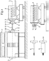
- Fig. 1 a schematic side view of an arrangement according to the invention or a system according to the invention
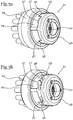
- Fig. 2 a schematic sectional view of a shaft connection device
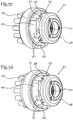
- Fig. 3 different positions of a shaft connection device
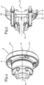
- Fig. 4 a schematic oblique view of part of the arrangement and in particular the test specimen coupling device
- Fig. 5 a sectional representation of the schematic view of the test specimen coupling device
- Fig. 6 show the function of the axial connection device.
- the reference symbols correspond to the following components: loading machine connection component 1, loading machine 2, test piece connection component 3, test piece 4, axis of rotation 5, shaft 6, load machine coupling device 7, test piece coupling device 8, test piece adapter 9, shaft adapter 10, form-fit element 11, axial connection device 12, clamping web 13 , Clamping body 14, opening 15, connecting element 16, clamping web release 17, shaft 18, insertion release 19, bayonet ring 20, shaft connection device 21, hub 22, axial locking element 23, axial locking opening 24, actuating device 25, locking lug 26, locking recess 27, stop body 28, actuating element 29, elastic Element 30, control surface 31, elastic coupling 32.
- Fig. 1 shows a schematic side view of an arrangement according to the invention or a system according to the invention which contains an arrangement according to the invention.
- the arrangement comprises a loading machine coupling device 7 for connecting a shaft 6 to the loading machine connection component 1 of a loading machine 2.
- the arrangement comprises a test piece coupling device 8 for connecting the shaft 6 to the test piece connection component 3 of a test piece 4 the arrangement also includes the loading machine 2 and / or the test object 4.
- the arrangement or the system preferably comprises several shafts 6 which can have different physical properties such as different stiffnesses.
- the loading machine coupling device 7 preferably comprises a shaft connection device 21 and possibly an elastic coupling 32.
- the test piece coupling device 8 preferably comprises a shaft adapter 10, a test piece adapter 9 and an axial connection device 12.
- the system or the arrangement can comprise a further test piece 4, which preferably also has a Test specimen adapter 9 is provided so that the test specimens can optionally be connected with their test specimen adapter 9 to the loading machine 2 and in particular to the shaft adapter 10.
- the exchangeable shafts 6 are each provided with a shaft adapter 10.
- the arrangement or the system is preferably designed such that all shaft adapters 10 can be connected to all test specimen adapters 9.
- the shafts preferably have a section for connection to the hub 22 of the shaft connection device 21. These shaft sections of all shafts 6 are preferably designed to be identical or identical in shape, so that the shafts can optionally be connected to the loading machine 2 via the shaft connection device 21 and exchanged.
- the present system or the present arrangement enables the test objects 4 and the shafts 6 to be exchanged quickly and efficiently.
- different test objects 4 and different shafts 6 can be connected one after the other or alternatively with the loading machine 2, whereby the changeover time and the operability are improved.
- Fig. 2 shows two schematic sectional views of a shaft connection device 21 in different positions, wherein Fig. 2a shows the shaft connection device 21 in its open position, in which a shaft 6 can be introduced into the hub 22 in the axial direction, ie along the axis of rotation 5, or can be pulled out of the hub.
- Figure 2b shows the same coupling device as Fig. 2a , but in the closed position in which the axial degree of freedom of the shaft-hub connection is blocked, so that the shaft 6 is axially secured in the shaft connection device 21.
- the shaft connection device 21 is suitable and / or set up for the form-fitting rotary connection of a shaft 6 with a hub 22.
- the shaft-hub connection is preferably designed as a positive-locking rotary connection, in particular as a splined shaft arrangement, as a shaft-hub connection with serration or as a toothed shaft connection.
- This shaft-hub connection preferably includes an axial degree of freedom, so that the shaft 6 or at least a section of the shaft 6 can be inserted into the hub 22 or removed from the hub 22.
- At least one axial securing element 23 is provided, which protrudes into an axial securing opening 24 to block the axial degree of freedom of the shaft-hub connection.
- a plurality of axial securing elements 23 are preferably provided. These can, for example, protrude into an axial securing opening 24 arranged in a ring. If necessary, several axial securing openings 24 are provided, which are designed in such a way that one axial securing element 23 or several axial securing elements 23 can each protrude into one of the axial securing openings 24 in order to block the axial degree of freedom of the shaft-hub connection.
- the axial securing openings 24 are preferably formed in all embodiments by an annular groove and preferably by a single annular groove, which is provided in particular in the area of the shaft section received in the hub 22 is, so that there is no exact rotational alignment of the axial locking openings 24 with respect to the axial locking elements 23.
- the axial securing elements 23 are preferably movable and in particular guided or arranged in a sliding bushing in the hub 22.
- the axial securing elements 23 have an extended position in which they protrude inwardly beyond the hub in order to be introduced into the axial securing openings 24 of the shaft 6, for example.
- the axial securing elements 23 have a retracted position in which they are withdrawn into the hub 22 in such a way that the axial degree of freedom of the shaft-hub connection is released.
- An actuating device 25 is provided for moving or actuating the axial securing elements 23.
- the actuating device 25 comprises an open position in which the axial securing elements 23 are preferably in their retracted position. Furthermore, the actuating device 25 comprises a closed position in which the axial securing elements 23 are preferably in their extended position. It is preferably provided in all embodiments that the actuating device 25 can be latched both in its open position and in its closed position, so that the actuating device 25, in particular, cannot automatically switch from the open position to the closed position or from the closed position to the open position.
- the function of the locking is particularly in the Figures 3a to 3d described.
- the actuating device 25 preferably comprises a stop body 28 and an actuating element 29 which can be moved and locked in relation to the stop body 28.
- the stop body 28 is preferably rigidly connected to the hub 22.
- the shaft connection device 21 preferably comprises an elastic element 30, which is set up to exert a force and, for example, as a compression spring, tension spring or the like Element is formed.
- the elastic element 30 acts on the actuating element 29 and presses the actuating element 29 preferably against the stop body 28. Due to the elastic design of the elastic element 30 and a certain range of motion of the actuating element 29, the actuating element 29 can in the axial direction against the force of the elastic element 30 can be moved. In particular, the actuating element 29 in all embodiments can be moved against the force of the elastic element 30 in such a way that the latching of the actuating device 25 can be released.
- the actuating device 25 comprises at least one control surface 31 for moving the at least one axial securing element 23.
- a control surface 31 is preferably provided, via which a plurality of axial securing elements 23 can be moved.
- the control surface 31 is preferably arranged obliquely along the axial direction of the actuating element 29, whereby in the event of an axial displacement of the actuating element 29, in particular against or with the force of the elastic element 30, the control surface 31 changes the position of the axial securing element 23 or the axial securing elements 23 can.
- the control surface 31 can be designed essentially conical and in particular as an inner conical ring.
- the control surface 31, designed as a conical surface comes into contact with sections of the axial securing elements 23, whereby these are moved from their retracted position to their extended position or from their extended position to their retracted position due to the inclined arrangement of the control surface 31 can.
- the control surface 31, an axial securing element 23 and an axial securing opening 24 are shown enlarged in the open position and the closed position of the actuating device 25.
- a further elastic element 30 is preferably provided, which is suitable and / or designed to move the axial securing element (s) 23.
- the control surface 31 can thus be set up to actively drive a movement of the axial securing elements 23 only in one direction.
- the axial securing elements 23 can be reset, for example, via the elastic element 30, which is designed, for example, as a compression spring.
- the elastic element 30 preferably presses the axial securing element 23 or the axial securing elements 23 against the control surface 31 and thereby elastically counteracts the control or the movement through the control surface 31. As a result, it can be effected, for example, that the axial securing elements 23, driven by the elastic element 30, automatically return to their retracted position when the actuating device 25 is in its open position.
- Figure 2b shows the same device as Fig. 2a , wherein the shaft connection device 21 of Figure 2b is in its closed position.
- the components of the Figure 2b correspond to the components of Fig. 2a .
- the shaft 6 is centered in the hub 22 via a fit, in particular a double fit.
- Both the shaft journal and a shaft shoulder arranged at a distance from the shaft journal are centered in the area of the hub by means of a corresponding fit.
- the Figures 3a to 3d show different positions of a shaft connection device 21, in particular according to FIG Fig. 2a and according to Figure 2b can be designed.
- the shaft connection device 21 comprises a hub 22 for introducing a shaft, not shown.
- the shaft connection device 21 comprises an actuating device 25.
- the actuating device 25 comprises a stop body 28 and an actuating element 29.
- the actuating element 29 is arranged to be movable relative to the stop body 28.
- the actuating device 25 comprises at least one locking lug 26 and at least two latching recesses 27.
- the latching recesses 27 are designed in such a way that the latching lug 26 can optionally be inserted into one of the latching recesses 27.
- the insertion or extraction direction preferably runs approximately axially.
- the locking lug 26 can be removed from one of the locking recesses 27 in the axial direction.
- This movement of the actuating element 29 preferably takes place against the force of an elastic element 30.
- the elastic element 30 is preferably pretensioned in such a way that the actuating element 29 is pressed against the stop body 28.
- the locking lug 26 is pressed into one of the locking recesses 27 by the elastic element 30.
- the actuating device 25 and in particular the actuating element 29 have an intermediate position. In this intermediate position, the locking lug is removed from the locking recess.
- the actuating element 29 in the present embodiment can be rotated relative to the stop body 28.
- the latching recesses 27 are preferably arranged along a pitch circle of the axis of rotation, so that by rotating the actuating element 29 relative to the stop body 28, the choice between the open position and the closed position can be made.
- the latching recesses 27 or the latching lug 26 are preferably designed such that when the latching lug 26 is inserted in a latching recess 27, a rotation or a change between the open position and the closed position is positively prevented.
- the latching recesses 27 are provided in the actuating element 29.
- the locking lug 26 is provided on the stop body 28.
- the locking recesses 27, which are assigned to a locking lug 26, have a different depth in the axial direction, whereby the locking lug 26 can be inserted deeper into one locking recess 27 than into the other Locking recess 27.
- the actuating element 29 thus has a different axial position, depending on which of the two locking recesses 27 the locking lug 26 is inserted into. This difference in the axial position has the effect that the axial securing elements 23, influenced by the control surface 31, are in their extended position when the locking lug 26 is arranged in one of the locking recesses, and that the axial securing elements 23 are in their retracted position when the locking lug 26 is arranged in the other locking recess 27,
- Fig. 3a shows the shaft connection device 21 in which the actuating device 25 is in its open position.
- Figure 3b shows the shaft connection device 21 or its actuating device 25 in an intermediate position in which the locking lug 26 is pulled out of the locking recess 27. This separation takes place by moving the actuating element 29 away from the stop body 28, and in particular against the spring force of the elastic element 30.
- Figure 3c shows the shaft connection device 21 or the actuating device 25 in a further intermediate position in which the locking lug 26 is rotated relative to the second locking recess 27.
- Fig. 3d shows the shaft connection device 21 or its actuating device 25, in which the locking lug 26 is inserted into the other locking recess 27 so that the actuating device 25 is in its closed position.
- the latching lug 26 In order to introduce a latching lug 26 into a latching recess 27, the latching lug 26 must preferably be arranged in alignment with one of the latching recesses 27.
- the position of Fig. 3a corresponds to the position of the Fig. 2a .
- the position of Fig. 3d corresponds to the position of the Figure 2b .
- the latching lug 26 or the latching recesses 27 are designed on the outside and can therefore serve as an indicator for displaying the position of the actuating device 25.
- Fig. 4 shows a schematic oblique view of part of the arrangement and in particular of the test specimen coupling device 8.
- the test specimen coupling device 8 comprises a shaft adapter 10, a test specimen adapter 9 and an axial connection device 12 for axially connecting the shaft adapter 10 to the test specimen adapter 9.
- the axial connection device 12 is preferably not used for transmission of the torque from the test piece connection component 3 of the test piece 4 to the shaft 6, but only for the axial securing and for the connection of the test piece adapter 9 with the shaft adapter 10.
- the torque is transmitted via positive locking elements 11 through which the test piece adapter 9 is positively rotatably connected to the shaft adapter 10 is.
- FIG. 13 shows a sectional illustration of the schematic view of the test specimen coupling device 8 or parts of the arrangement of FIG Fig. 4 .
- the shaft 6 has a flexible shaft connection and, in particular, a constant velocity joint at its end arranged in the test specimen coupling device 8.
- the test piece adapter 9 is set up to be connected to the test piece connection component 3 of the test piece 4. This connection takes place in the present case and preferably in all embodiments via a screw or flange connection.
- the shaft adapter 10 is connected to the constant velocity joint of the shaft 6.
- any connection can be used which enables the shaft adapter 10 to be connected to the shaft 6 in the present arrangement.
- the Figures 6a , 6b and 6c show the function of the axial connection device 12 for the axial connection of the test specimen adapter 9 to the shaft adapter 10.
- Both the test specimen adapter 9 and the shaft adapter 10 include form-fit elements 11. These form-fit elements 11 are in particular on the mutually facing Sides of the shaft adapter 10 and the test specimen adapter 9 are provided.
- the form-fit elements 11 are set up in particular to produce a form-fit rotary connection between the shaft adapter 10 and the test piece adapter 9.
- the form-locking elements 11 of the two adapters 9, 10 are designed to be plugged into one another in the axial direction, that is to say along the axis of rotation 5.
- the form-fit elements 11 are set up for the transmission and in particular for the form-fit rotary transmission of the torque.
- the axial connection device 12 is provided for the axial connection and thus for the axial securing of this rotary connection.
- the test specimen adapter 9 and the shaft adapter 10 form a clamping web 13 when the positive rotary connection is established.
- This clamping web 13 is clamped between two clamping bodies 14 in order to establish an axial connection between the test specimen adapter 9 and the shaft adapter 10.
- a section of the shaft adapter 10 and of the test specimen adapter 9 can run parallel along the course of the clamping web 13 and essentially transversely or normal to the clamping force of the clamping bodies 14.
- the test specimen adapter 9 and the shaft adapter 10 preferably comprise openings 15 running in the axial direction, which are in particular designed as through openings.
- the axial connection device 12 comprises connection elements 16 which can be passed through the openings 15.
- the connecting elements 16 preferably include a shaft 18 which protrudes through the opening 15 in order to connect the two clamping bodies 14 to one another in such a way that they cause the clamping web to jam.
- the openings 15 each preferably include a clamping web exposure 17 and an insertion exposure 19. Due to the special design of the openings 15 and the axial connection device 12, they are bayonet-like actuatable axial connection device 12 is formed.
- the connecting elements 16 can be introduced essentially in the axial direction through the openings 15 and, in particular, through the insertion clearance 19 of the opening 15. In this position, the connecting element 16 can then be moved into the clamping web release position 17 by means of a rotary movement.
- the shaft 18 of the connecting element 16 is designed in such a way that it fits into the clamping web clearance 17.
- Figure 6b shows a position in which the connecting elements 16 are inserted into the insertion free position 19.
- Figure 6c shows a position in which the connecting elements 16 are inserted into the clamping web clearances 17 via a rotary movement.
- the connecting elements 16 comprise two clamping bodies 14, one clamping body 14 being configured as a screw head or as a screw nut and the other clamping element 14 as a tab or web.
- a plurality of connecting elements 16 are preferably connected to one another via a bayonet ring 20.
- the connecting elements 16 are arranged along the course of the bayonet ring 20 in such a way that they can be inserted into the openings 15 of the adapters 9, 10.
- Those designed as webs or tabs are preferred Clamping body 14 connected to the bayonet ring, and optionally connected in one piece.
- the clamping bodies, which are designed as webs or tabs, preferably protrude inward from the bayonet ring 20.
- the clamping web 13 as in particular in the Figures 6 is shown, formed substantially C-shaped, the legs of the clamping web 13 extending substantially along a pitch circle around the axis of rotation 5.
- the C-shaped clamping web 13 has an opening 15 which is formed in particular by the clamping web release 17.
- the clamping web release 17 is essentially in the form of a slot and / or following a pitch circle around the axis of rotation 5.
- the clamping web release 17 opens into the insertion release 19 of the opening 15, as a result of which a connecting element 16 inserted through the insertion release 19 can subsequently be inserted into the clamping web release 17.
- the form-locking elements 11, or their form-locking flanks can be provided between the openings 15. If necessary, only one opening 15 and one connecting element 16 are provided. If necessary, two, three, four, five or more connecting elements 16 with correspondingly arranged openings 15 are provided.
- the arrangement comprises a test piece coupling device 8, which according to one of the Figures 4, 5 or 6th is trained.
- This arrangement preferably comprises a loading machine coupling device which, according to one of the Figures 2 or 3 is trained.
Description
- Die Erfindung betrifft eine Anordnung und eine Vorrichtung gemäß Oberbegriff der unabhängigen Patentansprüche. Insbesondere betrifft die Erfindung eine Anordnung zur Verbindung einer Belastungsmaschine eines Prüfstandes, insbesondere eines Motorenprüfstandes oder eines Antriebsprüfstandes mit einem Prüfling.
- Als Belastungsmaschinen werden Baugruppen bezeichnet, die beispielsweise passive Belastungsmaschinen wie Wasserwirbelbremsen, Wirbelstrombremsen, Hysteresebremsen oder Magnetpulverbremsen; aktive Belastungsmaschinen wie Gleichstrommaschinen, Asynchronmaschinen oder Drehstrom-Synchronmaschinen, aber gegebenenfalls auch Drehmoment-Messeinrichtungen, Drehmomenten-Waagen, Gleichstrom-Pendelmaschinen und/oder Tachogeneratoren als Drehzahl-Messeinrichtungen umfassen können. Als Prüfling wird allgemein die zu prüfende Vorrichtung bezeichnet, die beispielsweise eine Antriebsvorrichtung, einen Verbrennungsmotor, einen Antriebsstrang und/oder ein Getriebe umfassen kann.
- Anordnungen zur Verbindung von Prüflingen mit Belastungsmaschinen sind in unterschiedlichen Ausführungen bekannt und publiziert.
- Herkömmliche Verbindungsanordnungen umfassen meist eine Welle, die an ihren Enden über Gleichlaufgelenke mit je einer Kupplungsvorrichtung verbunden ist, wobei die Kupplungsvorrichtungen gegebenenfalls als elastische Kupplungen ausgebildet sind. Die Kupplungsvorrichtungen selbst sind meist über Schraubverbindungen oder Flanschverbindungen fest mit der Belastungsmaschine des Prüfstands bzw. dem Prüfling verbunden.
- Aus der praktischen Anwendung von Prüfständen besteht eine Nachfrage nach Anordnungen zur Drehverbindung der Belastungsmaschine mit dem Prüfling, deren Drehsteifigkeit und/oder Drehdämpfung variiert werden kann. Zur grundsätzlichen Lösung dieses Problems werden derzeit Wellen mit unterschiedlichen Steifigkeiten eingesetzt. Das Umrüsten und insbesondere das Wechseln der Wellen ist jedoch bei herkömmlichen Vorrichtungen mit einem erheblichen Zeit- und Arbeitsaufwand verbunden, wobei sich der Umrüstaufwand besonders negativ auswirkt, wenn mehrere Motoren bzw. Prüflinge nacheinander mit dem Prüfstand verbunden werden sollen.
- So offenbart die
US 4,191,487 eine Anordnung zur Verbindung einer mittleren Welle, welche beidseitig über einen Wellenflansch an jeweils eine weiterführende Welle anschließbar ist. In Umfangsrichtung wird die Lage der Wellen zueinander über Vorsprünge und korrespondirende Ausnehmungen, die ineinander greifen und als Formschlusselemente dienen, festgelegt. Anschließend werden die Wellenflansche miteinander verschraubt, wodurch eine Axialverbindung hergestellt wird. - Des Weiteren ist aus der
CN 203348358 U ebenfalls eine Anordnung zur beidseitigen Verbindung einer Welle an beidseitig weiterführende Wellen bekannt. Der Formschluss zwischen den gegenüberliegenden Wellenenden wird auch hier durch ineinandergreifende Vorsprünge und korrespondierende Ausnehmungen an den zueinander gerichteten Wellenenden hergestellt. Zur Axialsicherung sind die Wellenenden radial erweitert, wobei über die aneinander liegenden Wellenerweiterungen eine Flanschklemme montiert wird. - Eine ohne Werkzeuge lösbare und herstellbare Wellenendenverbindung wird nicht offenbart.
- Aufgabe der Erfindung ist es nun, eine Anordnung bzw. eine Vorrichtung zur Drehverbindung der Belastungsmaschinenanschlusskomponente einer Belastungsmaschine mit der Prüflingsanschlusskomponente eines Prüflings zu schaffen, die die Nachteile des Standes der Technik überwinden. Insbesondere soll eine schnelle und unkomplizierte Umrüstung der Verbindungskomponenten ermöglicht werden.
- Die erfindungsgemäße Aufgabe wird insbesondere durch die Merkmalskombinationen der unabhängigen Patentansprüche gelöst.
- Die Erfindung umfasst eine Anordnung zur Drehverbindung der Belastungsmaschinenanschlusskomponente einer Belastungsmaschine eines Prüfstandes mit der Prüflingsanschlusskomponente eines Prüflings, umfassend mindestens eine entlang der Drehachse der Drehverbindung verlaufende Welle, eine zwischen der Welle und der Belastungsmaschinenanschlusskomponente der Belastungsmaschine angeordnete Belastungsmaschinenkupplungsvorrichtung zur Drehverbindung der Welle mit der Belastungsmaschinenanschlusskomponente, eine zwischen der Welle und der Prüflingsanschlusskomponente des Prüflings vorgesehene Prüflingskupplungsvorrichtung zur Drehverbindung der Welle mit der Prüflingsanschlusskomponente.
- Die Prüflingskupplungsvorrichtung umfasst mindestens einen mit der Prüflingsanschlusskomponente eines Prüflings verbindbaren Prüflingsadapter und einen mit der Welle verbindbaren oder verbundenen Wellenadapter, der Prüflingsadapter und der Wellenadapter umfassen Formschlusselemente zur lösbaren und formschlüssigen Drehverbindung des Prüflingsadapters mit dem Wellenadapter, undes ist eine Axialverbindungsvorrichtung zur axialen Verbindung des Prüflingsadapters mit dem Wellenadapter vorgesehen.
Die Axialverbindungsvorrichtung ist bajonettverschlussartig ausgebildet, der Klemmsteg ist durch einen Bewegungsablauf einer axialen Bewegung und einer Drehbewegung der Axialverbindungsvorrichtung zwischen den Klemmkörpern der Axialverbindungsvorrichtung anordenbar, und die Klemmkörper wirken als Axialsicherung gegen eine axiale Trennung des Prüflingsadapters vom Wellenadapter und als Verdrehsicherung für die bajonettverschlussartig ausgestaltete Axialverbindungsvorrichtung. - Gegebenenfalls ist vorgesehen, dass die Formschlusselemente von den einander zugewandten Seiten des Wellenadapters und des Prüflingsadapters im Wesentlichen entlang der Richtung der Drehachse, also axial abstehen und zur Herstellung der formschlüssigen Drehverbindung in axialer Richtung ineinandersteckbar und zur Trennung der formschlüssigen Drehverbindung in axialer Richtung voneinander entfernbar sind.
- Gegebenenfalls ist vorgesehen, dass der Prüflingsadapter und der Wellenadapter bei hergestellter formschlüssiger Drehverbindung zusammen einen Klemmsteg bilden, der zur axialen Verbindung des Prüflingsadapters mit dem Wellenadapter zwischen Klemmkörpern der Axialverbindungsvorrichtung eingeklemmt ist.
- Gegebenenfalls ist vorgesehen, dass der Prüflingsadapter und der Wellenadapter in axialer Richtung verlaufende Öffnungen aufweisen, dass die mindestens eine Öffnung des Prüflingsadapters mit der mindestens eine Öffnung des Wellenadapters zumindest teilweise fluchtend angeordnet ist, wenn die Formschlusselemente des Prüflingsadapters mit den Formschlusselementen des Wellenadapters zur Drehverbindung in Eingriff stehen, und/oder dass die Axialverbindungsvorrichtung mindestens ein Verbindungselement umfasst, das zur axialen Verbindung des Prüflingsadapters mit dem Wellenadapter durch die Öffnungen hindurchragen.
- Gegebenenfalls ist vorgesehen, dass der Prüflingsadapter und der Wellenadapter in axialer Richtung verlaufende Öffnungen aufweisen, dass die Öffnungen des Prüflingsadapters mit den Öffnungen des Wellenadapters zumindest teilweise fluchtend angeordnet sind, wenn die Formschlusselemente des Prüflingsadapters mit den Formschlusselementen des Wellenadapters zur Drehverbindung in Eingriff stehen, dass die Axialverbindungsvorrichtung Verbindungselemente umfasst, die zur axialen Verbindung des Prüflingsadapters mit dem Wellenadapter durch die Öffnungen hindurchragen, dass die Öffnungen jeweils eine Einführfreistellung zur axialen Einführung des Verbindungselements der Axialverbindungsvorrichtung und eine Klemmstegfreistellung zur axialen Verbindung des Prüflingsadapters mit dem Wellenadapter durch Betätigen des Verbindungselements umfassen, wobei die Klemmstegfreistellung entlang eines Teilkreises um die Drehachse verläuft und insbesondere gekrümmt langlochförmig ausgebildet ist, dass die Verbindungselemente jeweils einen Schaft mit einer Schaftdicke und zwei die Schaftdicke überragende Klemmkörper aufweisen, dass die Klemmstegfreistellung quer zu ihrem Verlauf und insbesondere in radialer Richtung eine freie Breite aufweist, die größer ist als die Schaftdicke des Schafts des jeweiligen Verbindungselements aber von den beiden Klemmkörpern des Verbindungselements überragt wird, dass die Einführfreistellung größer ist als der maßgebliche Abschnitt zumindest einer der beiden Klemmkörper oder beider Klemmkörper des Verbindungselements, sodass die Verbindungselemente der Axialverbindungsvorrichtung bajonettverschlussartig in axialer Richtung in die Einführfreistellungen der Öffnungen einführbar, entlang des Verlaufs der Klemmstegfreistellungen der Öffnungen um die Drehachse verdrehbar, und durch Einklemmen des Klemmstegs zwischen den Klemmkörpern fixierbar sind.
- Gegebenenfalls ist vorgesehen, dass die Verbindungselemente jeweils eine Schraubverbindung umfassen, wobei der Schaft des Verbindungselements ein Schraubenschaft ist, der in zumindest einen der beiden Klemmkörper eingeschraubt oder einschraubbar ist, und dass der Abstand und die Klemmkraft zwischen den beiden Klemmkörpern durch Veränderung der Einschraubtiefe veränderbar ist.
- Gegebenenfalls ist vorgesehen, dass die Axialverbindungsvorrichtung einen Bajonettring umfasst, über den die Verbindungselemente der Axialverbindungsvorrichtung miteinander verbunden sind.
- Gegebenenfalls ist vorgesehen, dass die Formschlusselemente des Prüflingsadapters im Wesentlichen eine funktionale Negativform der Formschlusselemente des Wellenadapters aufweisen, wobei die Formschlusselemente des Prüflingsadapters und die Formschlusselemente des Wellenadapters zusammen eine im Wesentlichen spielfreie, formschlüssige Drehverbindung bilden oder eine im Wesentlichen in beide Drehrichtungen spielfreie, formschlüssige Drehverbindung bilden.
- Gegebenenfalls ist vorgesehen, dass die Prüflingskupplungsvorrichtung zur Anbindung an die Welle eine flexible Wellenverbindung, ein Kreuzgelenk oder ein Gleichlaufgelenk aufweist.
- Gegebenenfalls betrifft die Erfindung ein System umfassend eine Anordnung wobei mehrere Wellen mit unterschiedlichen Steifigkeiten vorgesehen oder bereitgestellt sind, die zur Veränderung der Steifigkeit des Messstranges der Anordnung wahlweise zur Verbindung der Belastungsmaschinenkupplungsvorrichtung mit der Prüflingskupplungsvorrichtung einsetzbar sind.
- Gegebenenfalls ist vorgesehen, dass mehrere Wellen mit unterschiedlichen Steifigkeiten vorgesehen oder bereitgestellt sind, die zur Veränderung der Steifigkeit des Messstranges der Anordnung wahlweise zur Verbindung der Belastungsmaschinenkupplungsvorrichtung mit der Prüflingskupplungsvorrichtung einsetzbar sind, und dass die Wellen jeweils mit einem Wellenadapter verbunden sind.
- Gegebenenfalls ist vorgesehen, dass mehrere Prüflinge vorgesehen sind, die jeweils mit einem Prüflingsadapter verbunden sind, wobei die Prüflinge und deren Prüflingsadapter wahlweise durch Verbinden mit dem Wellenadapter mit der Belastungsmaschine verbindbar sind.
- Gegebenenfalls ist vorgesehen, dass die Formschlusselemente aller Wellenadapter zur formschlüssigen Drehverbindung mit den Formschlusselementen aller Prüflingsadapter geeignet und eingerichtet sind.
- Gegebenenfalls ist vorgesehen, dass die Anordnung oder das System eine Belastungsmaschine eines Prüfstandes oder eines Motorenprüfstandes umfasst.
- Gegebenenfalls umfasst die Erfindung eine Wellenverbindungsvorrichtung zur formschlüssigen Drehverbindung einer Nabe mit einer Welle, wobei die Wellenverbindungsvorrichtung eine formschlüssig wirkende Welle-Nabe-Verbindung umfasst, wobei die Welle-Nabe-Verbindung einen axialen Freiheitsgrad zum Einführen eines Wellenabschnitts der Welle in die Nabe und zum Entfernen des Wellenabschnitts der Welle aus der Nabe aufweist, wobei die Wellenverbindungsvorrichtung mindestens ein Axialsicherungselement zur axialen Sicherung der Welle-Nabe-Verbindung umfasst, wobei das Axialsicherungselement eine ausgefahrene Stellung aufweist, in der es in eine Axialsicherungsöffnung ragt, wodurch der axiale Freiheitsgrad der Welle-Nabe-Verbindung gesperrt ist, und wobei das Axialsicherungselement eine zurückgezogene Stellung aufweist, in der der axiale Freiheitsgrad der Welle-Nabe-Verbindung freigegeben ist.
- Gegebenenfalls ist vorgesehen, dass die Wellenverbindungsvorrichtung eine Betätigungsvorrichtung zur Betätigung des Axialsicherungselements umfasst, dass die Betätigungsvorrichtung gegebenenfalls in einer Offenstellung verrastbar ist, in der das Axialsicherungselement in seine zurückgezogene Stellung bringbar oder gebracht ist, und/oder dass die Betätigungsvorrichtung gegebenenfalls in einer Geschlossenstellung verrastbar ist, in der das Axialsicherungselement in seine ausgefahrene Stellung bringbar oder gebracht ist.
- Gegebenenfalls ist vorgesehen, dass die Betätigungsvorrichtung mindestens eine Rastnase, mindesten zwei Rastausnehmungen, einen starr mit der Nabe verbundenen Anschlagkörper, und ein gegenüber dem Anschlagkörper bewegbares und durch Einführen der Rastnase in eine der Rastausnehmung gegenüber dem Anschlagkörper verrastbares Betätigungselement umfasst, wobei die Betätigungsvorrichtung in ihrer Offenstellung verrastet ist, wenn die Rastnase in einer der beiden zugeordneten Rastausnehmungen angeordnet ist, und wobei die Betätigungsvorrichtung in ihrer Geschlossenstellung verrastet ist, wenn die Rastnase in der anderen der beiden zugeordneten Rastausnehmungen angeordnet ist.
- Gegebenenfalls ist vorgesehen, dass die Rastnase und die Rastausnehmungen im Wesentlichen entlang einer axialer Richtung verlaufen, und dass, wenn die Rastnase in eine der Rastausnehmungen eingeführt ist, das Betätigungselement und der Anschlagkörper einen axialen Freiheitsgrad gegenübereinander aufweisen, aber eine Verdrehung des Betätigungselements gegenüber dem Anschlagkörper im Wesentlichen gehemmt, insbesondere formschlüssig gehemmt ist.
- Gegebenenfalls ist vorgesehen, dass die Betätigungsvorrichtung zum Wechsel zwischen der Offenstellung und der Geschlossenstellung eine Zwischenstellung aufweist, in der die Rastnase außerhalb der Rastausnehmungen angeordnet ist, dass das Betätigungselement in der Zwischenstellung gegenüber dem Anschlagkörper einen Drehfreiheitsgrad aufweist, und dass die Rastnase zur Verrastung der Betätigungsvorrichtung in der Offenstellung oder in der Geschlossenstellung wahlweise in eine der zugeordneten Rastausnehmungen einführbar oder eingeführt ist.
- Gegebenenfalls ist vorgesehen, dass die Betätigungsvorrichtung ein axial wirkendes elastisches Element, wie insbesondere eine Druckfeder aufweist, dessen Kraft das Betätigungselement gegen den Anschlagkörper und gegebenenfalls die Rastnase in eine Rastausnehmung drückt und dessen Kraft einer Bewegung des Betätigungselements von einer verrasteten Stellung in die Zwischenstellung entgegenwirkt.
- Gegebenenfalls ist vorgesehen, dass die Betätigungsvorrichtung mindestens eine Steuerfläche zur Bewegung des Axialsicherungselements von seiner zurückgezogenen Stellung in die ausgefahrene Stellung durch Bewegung der Betätigungsvorrichtung von der Offenstellung in die Geschlossenstellung aufweist.
- Gegebenenfalls ist vorgesehen, dass die Steuerfläche am Betätigungselement vorgesehen ist, dass die Steuerfläche entlang der axialen Richtung schräg nach innen verläuft und insbesondere der Form eines Innenkegelrings entspricht, und dass sich das Axialsicherungselement je nach axialer Position des Betätigungselements in seiner ausgefahrenen Stellung oder in seiner zurückgezogenen Stellung befindet.
- Gegebenenfalls ist vorgesehen, dass die Rastausnehmungen beabstandet voneinander entlang des Drehfreiheitsgrades des Betätigungselements angeordnet sind, und/oder dass eine Rastausnehmung entlang der axialen Richtung tiefer ausgebildet ist als eine andere Rastausnehmung.
- Gegebenenfalls ist vorgesehen, dass mehrere Axialsicherungselemente in radialer Richtung in der Nabe oder jeweils in einer in der Nabe angeordneten Gleitbuchse geführt angeordnet sind und in ihrer ausgefahrenen Stellung von der Nabe radial nach innen, und zur axialen Sicherung in eine in der Welle vorgesehene ringnutförmige Axialsicherungsöffnung oder in mehrere Axialsicherungsöffnungen ragen.
- Gegebenenfalls umfasst die Erfindung eine Anordnung zur Drehverbindung der Belastungsmaschinenanschlusskomponente einer Belastungsmaschine mit der Prüflingsanschlusskomponente eines Prüflings, umfassend mindestens eine entlang der Drehachse der Drehverbindung verlaufende Welle, eine zwischen der Welle und der Belastungsmaschinenanschlusskomponente der Belastungsmaschine angeordnete Belastungsmaschinenkupplungsvorrichtung zur Drehverbindung der Welle mit der Belastungsmaschinenanschlusskomponente, eine zwischen der Welle und der Prüflingsanschlusskomponente des Prüflings vorgesehene Prüflingskupplungsvorrichtung zur Drehverbindung der Welle mit der Prüflingsanschlusskomponente, wobei die Belastungsmaschinenkupplungsvorrichtung und/oder gegebenenfalls die Prüflingskupplungsvorrichtung zur formschlüssigen Drehverbindung mit der Welle eine Wellenverbindungsvorrichtung gemäß der gegenständlichen Beschreibung umfasst.
- Gegebenenfalls ist vorgesehen, dass die Belastungsmaschinenkupplungsvorrichtung eine elastische Kupplung umfasst, oder dass die Belastungsmaschinenkupplungsvorrichtung eine entlang des Kraftflusses des Messstrangs zwischen der Nabe und der Belastungsmaschinenanschlusskomponente der Belastungsmaschine angeordnete elastische Kupplung umfasst.
- Gegebenenfalls ist vorgesehen, dass die Welle-Nabe-Verbindung als Kerbverzahnung, Keilwellenverbindung oder Zahnwellenverbindung ausgebildet ist.
- Gegebenenfalls ist vorgesehen, dass die Welle in der Nabe über eine Passung, insbesondere über eine Doppelpassung axial zentriert ist, und insbesondere dass sowohl der Wellenzapfen der Welle als auch eine entfernt vom Wellenzapfen angeordnete Wellenschulter über eine entsprechende Passung im Bereich der Nabe zentriert sind, oder dass die Welle beidseitig der Welle-Nabe-Verbindung zentriert ist.
- Gegebenenfalls ist vorgesehen, dass die Prüflingskupplungsvorrichtung mindestens einen mit der Prüflingsanschlusskomponente eines Prüflings verbindbaren oder verbundenen Prüflingsadapter und einen mit der Welle verbindbaren oder verbundenen Wellenadapter umfasst, dass der Prüflingsadapter und der Wellenadapter Formschlusselemente zur lösbaren und formschlüssigen Drehverbindung des Prüflingsadapters mit dem Wellenadapter umfassen, und dass eine Axialverbindungsvorrichtung zur axialen Verbindung des Prüflingsadapters mit dem Wellenadapter vorgesehen ist.
- Gegebenenfalls ist vorgesehen, dass mehrere Wellen mit unterschiedlichen Steifigkeiten vorgesehen oder bereitgestellt sind, die zur Veränderung der Steifigkeit des Messstranges der Anordnung wahlweise zur Verbindung der Belastungsmaschinenkupplungsvorrichtung mit der Prüflingskupplungsvorrichtung einsetzbar sind.
- Gegebenenfalls ist das Betätigungselement der Betätigungsvorrichtung in allen Ausführungsformen als werkzeuglos betätigbares Betätigungselement und insbesondere als manuell betätigbares Betätigungselement ausgebildet.
- Gegebenenfalls wird eine als System bezeichenbare Anordnung vorgeschlagen, die zumindest eine Welle, eine Belastungsmaschinenkupplungsvorrichtung zur Drehverbindung der Welle mit der Belastungsmaschinenanschlusskomponente der Belastungsmaschine und eine Prüflingskupplungsvorrichtung zur Drehverbindung der Welle mit der Prüflingsanschlusskomponente des Prüflings umfasst, wobei die Welle die Prüflingskupplungsvorrichtung und die Belastungsmaschinenkupplungsvorrichtung verbindet.
- Bevorzugt umfasst das System bzw. die Anordnung mehrere Wellen mit unterschiedlichen Steifigkeits- und/oder Dämpfungseigenschaften, die wahlweise zur Verbindung der Belastungsmaschinenkupplungsvorrichtung mit der Prüflingskupplungsvorrichtung eingesetzt werden können, um die Elastizität, die Resonanzparameter oder die Dämpfungseigenschaft des Messstrangs des Prüfstandsaufbaus an die jeweiligen Anforderungen anpassen zu können.
- Gegebenenfalls umfasst das System bzw. die Anordnung mehrere Prüflingsadapter, die jeweils mit einem Prüfling verbunden werden können oder sind und die bevorzugt an die Prüflingsanschlusskomponente des Prüflings angepasst sind. Dadurch können mehrere Prüflinge für die Verbindung mit der Belastungsmaschine des Prüfstands vorbereitet sein und über wenige Handgriffe mit der Belastungsmaschine verbunden werden.
- Auch ein Tausch der Welle ist durch die erfindungsgemäße Anordnung bzw. das erfindungsgemäße System erleichtert, da in bevorzugter Weise die Anschlussstücke der Welle an die Belastungsmaschinenkupplungsvorrichtung und an die Prüflingskupplungsvorrichtung standardisiert oder gleich ausgebildet ist. So weisen bevorzugt alle Prüflingsadapter dieselbe Anschlussgeometrie zur Verbindung mit dem oder den Wellenadapter(n) auf. Bevorzugt weisen alle Wellen dieselbe Anschlussgeometrie zur Verbindung mit der Prüflingskupplungsvorrichtung auf. Gegebenenfalls weist jede Welle einen eigenen Wellenadapter auf.
- Gegebenenfalls ist vorgesehen, dass die elastische Kupplung auswechselbar oder dauerhaft mit der Belastungsmaschinenanschlusskomponente der Belastungsmaschine verbunden ist.
- Bevorzugt ist vorgesehen, dass die Belastungsmaschinenkupplungsvorrichtung eine Wellenverbindungsvorrichtung umfasst, die als Schnellwechselsystem ausgebildet ist. Dazu ist eine Welle-Nabe-Verbindung vorgesehen, die zwar in Drehrichtung formschlüssig wirkt, jedoch einen axialen Freiheitsgrad zum Einführen der Welle oder zum Entfernen der Welle aufweist. Dieser axiale Freiheitsgrad kann durch Axialsicherungselemente gesperrt werden. Dazu weisen die Axialsicherungselemente eine ausgefahrene Stellung auf, in der sie in eine Axialsicherungsöffnung ragen, um den axialen Freiheitsgrad zu sperren und insbesondere, um den axialen Freiheitsgrad formschlüssig zu sperren.
- Zur Betätigung der Axialsicherungselemente ist bevorzugt eine Betätigungsvorrichtung vorgesehen, die eine Offenstellung und eine Geschlossenstellung aufweist. Die Betätigungsvorrichtung ist gegebenenfalls derart ausgestaltet, dass ein Indikator vorgesehen ist, der anzeigt, ob sich die Betätigungsvorrichtung, und damit auch die Wellenverbindungsvorrichtung, in ihrer Offenstellung oder in ihrer Geschlossenstellung befinden. Der Indikator ist bevorzugt durch eine Rastnase und/oder durch eine Rastausnehmung gebildet.
- Erfindungsgemäß ist insbesondere vorgesehen, dass die Betätigungsvorrichtung in ihrer Offenstellung und in ihrer Geschlossenstellung verrastbar ist, sodass sie ohne Zutun von außen in der jeweiligen Stellung verharrt, insbesondere bis die Stellung durch aktives Eingreifen einer Bedienperson verändert wird. Zur Betätigung der Betätigungsvorrichtung und zur Veränderung der Stellung ist insbesondere ein Betätigungselement vorgesehen. Dieses Betätigungselement weist eine Steuerfläche auf, die dazu eingerichtet ist, bei Bewegung des Betätigungselements die Axialsicherungselemente von ihrer zurückgezogenen Stellung in ihre ausgefahrene Stellung oder von ihrer ausgefahrenen Stellung in ihre zurückgezogene Stellung zu bewegen. Gegebenenfalls wird nur das Ausfahren oder das Zurückziehen aktiv durch das Betätigungselement bewirkt, wobei die jeweils andere Bewegung durch ein elastisches Element, wie beispielsweise durch eine vorspannbare oder vorgespannte Feder bewirkt wird. Gegebenenfalls ist in allen Ausführungsformen vorgesehen, dass das Betätigungselement ringförmig und insbesondere die Nabe ringförmig umgebend ausgebildet ist. Das Betätigungselement ist bevorzugt axial und rotatorisch geführt, wobei der rotatorische Freiheitsgrad des Betätigungselements bei in einer Rastausnehmung eingeführter Rastnase gesperrt ist. Bei in einer Rastausnehmung eingeführter Rastnase ist eine Verdrehung des Betätigungselements bevorzugt formschlüssig gesperrt. Gegebenenfalls ist vorgesehen, dass die Belastungsmaschinenkupplungsvorrichtung eine mit der Belastungsmaschinenanschlusskomponente des Prüfstands fest verbundene Elastikkupplung ist, an der die Wellenverbindungsvorrichtung vorgesehen ist.
- Gegebenenfalls ist vorgesehen, dass entlang des Verlaufs des Anschlagkörpers oder des Betätigungselements mehrere Rastnasen vorgesehen sind, wobei bevorzugt jeder Rastnase zwei Rastausnehmungen zugeordnet sind.
- Gemäß einer bevorzugten Ausführungsform der Anordnung ist vorgesehen, dass das Drehmoment entlang des Messstrangs, ausgehend von dem Prüfling, nacheinander von der Prüflingsanschlusskomponente des Prüflings, dem Prüflingsadapter, dem Wellenadapter, gegebenenfalls einem Gleichlaufgelenk, der Welle, der Welle-Nabe-Verbindung der Wellenverbindungsvorrichtung, gegebenenfalls einer elastischen Kupplung und dann auf die Belastungsmaschinenanschlusskomponente der Belastungsmaschine übertragen wird, sodass diese Komponenten entlang des Kraftflusses nacheinander angeordnet sind. Der Kraftfluss läuft bevorzugt in dieser Reihenfolge direkt über die genannten Komponenten. Gegebenenfalls geht der Kraftfluss von der Belastungsmaschine aus und verläuft folglich in die entgegengesetzte Richtung entlang der genannten Komponenten.
- Gegebenenfalls ist vorgesehen, dass die Wellenverbindungsvorrichtung und insbesondere deren Welle-Naben-Verbindung für die Drehmomentklassen 150Nm, 300Nm, 600Nm, 900Nm und/oder 1500 Nm (bei 8000rpm-10000rpm) ausgelegt sind Bevorzugt ist die Nabe aus legiertem Vergütungsstahl mit einer Festigkeit von mehr als 1400N/mm2 gefertigt. Die Oberfläche der verschiebbaren Teile der Wellenverbindungsvorrichtung weisen bevorzugt eine Härte von mehr als 55HRC auf.
- Bevorzugt umfasst die Prüflingskupplungsvorrichtung zur Drehverbindung des Prüflingsadapters mit dem Wellenadapter Formschlusselemente. Bevorzugt wird das Drehmoment vom Prüflingsadapter auf den Wellenadapter ausschließlich über diese Formschlusselemente übertragen. Um zu verhindern, dass sich die Formschlusselemente in axialer Richtung voneinander trennen, ist eine Axialverbindungsvorrichtung vorgesehen. Bevorzugt ist diese Axialverbindungsvorrichtung bajonettartig ausgebildet oder bajonettartig bedienbar und mit einer Verdrehsicherung versehen. Die Formschlusselemente wirken bevorzugt wie Klauen einer Klauenkupplung, wie Klauen einer in beide Drehrichtungen wirkenden Klauenkupplung oder wie Klauen einer in beide Richtungen unelastisch wirkenden Klauenkupplung.
- Die Welle-Nabe-Verbindung ist zur formschlüssigen Drehverbindung der Welle mit der Nabe eingerichtet, wobei bevorzugt die Übertragung des Drehmoments ausschließlich über die Welle-Nabe-Verbindung geschieht. Um zu verhindern, dass die Welle aus der Welle-Nabe-Verbindung gezogen werden kann, sind Axialsicherungselemente vorgesehen. Diese Axialsicherungselemente sind jedoch bevorzugt ausschließlich zur axialen Halterung der Welle in der Nabe und nicht zur Übertragung des Drehmoments eingerichtet. Bevorzugt ist die Nabe in einer elastischen Kupplung gehaltert, womit sowohl eine gewisse Drehelastizität, als auch eine gewisse Toleranz der axialen Abweichung des Verlaufs der Welle ermöglicht ist.
- Gegebenenfalls können sowohl an der Belastungsmaschinenkupplungsvorrichtung als auch an der Prüflingskupplungsvorrichtung elastische Gelenke, wie beispielsweise Gleichlaufgelenke vorgesehen sein. Gegebenenfalls können sowohl die Belastungsmaschinenkupplungsvorrichtung als auch die Prüflingskupplungsvorrichtung eine elastische Kupplung umfassen. Als elastische Kupplung wird insbesondere eine Drehelastische Kupplung, wie beispielsweise eine drehelastisch gelagerte Elastomerkupplung bezeichnet.
- Bevorzugt weist die Welle-Nabe-Verbindung der Wellenverbindungsvorrichtung eine Doppelpassung auf, wodurch die Ausrichtung der Achse der Welle gegenüber der Achse der Nabe festgelegt ist. Dabei ist bevorzugt beidseitig des in der Nabe angeordneten Wellenabschnitts der Welle ein Zentrierbereich vorgesehen, wobei die Zentrierbereiche mit einer Passung in entsprechenden Zentrierbereichen der Nabe angeordnet sind. Die Nabe kann in dieser Ausführungsform an einer elastischen Kupplung vorgesehen sein, um insbesondere eine geringfügige Achsabweichung kompensieren zu können. Am anderen Ende der Welle kann beispielsweise ein Gleichlaufgelenk vorgesehen sein. Durch diese Konfiguration ist ferner ermöglicht, dass lediglich ein Gleichlaufgelenk bzw. ein elastisches Gelenk vorgesehen sein muss, wobei an der anderen Kupplung bevorzugt eine elastische Kupplung vorgesehen ist.
- In weiterer Folge wird die Erfindung anhand der Figuren weiter beschrieben, wobei
Fig. 1 eine schematische Seitenansicht einer erfindungsgemäßen Anordnung bzw. eines erfindungsgemäßen Systems,Fig. 2 eine schematische Schnittdarstellungen einer Wellenverbindungsvorrichtung,Fig. 3 unterschiedliche Stellungen einer Wellenverbindungsvorrichtung,Fig. 4 eine schematische Schrägansicht eines Teils der Anordnung und insbesondere die Prüflingskupplungsvorrichtung,Fig. 5 eine Schnittdarstellung der schematischen Ansicht der Prüflingskupplungsvorrichtung undFig. 6 die Funktion der Axialverbindungsvorrichtung zeigen. - Wenn nicht anders angegeben, so entsprechen die Bezugszeichen folgenden Komponenten: Belastungsmaschinenanschlusskomponente 1, Belastungsmaschine 2, Prüflingsanschlusskomponente 3, Prüfling 4, Drehachse 5, Welle 6, Belastungsmaschinenkupplungsvorrichtung 7, Prüflingskupplungsvorrichtung 8, Prüflingsadapter 9, Wellenadapter 10, Formschlusselement 11, Axialverbindungsvorrichtung 12, Klemmsteg 13, Klemmkörper 14, Öffnung 15, Verbindungselement 16, Klemmstegfreistellung 17, Schaft 18, Einführfreistellung 19, Bajonettring 20, Wellenverbindungsvorrichtung 21, Nabe 22, Axialsicherungselement 23, Axialsicherungsöffnung 24, Betätigungsvorrichtung 25, Rastnase 26, Rastausnehmung 27, Anschlagkörper 28, Betätigungselement 29, elastisches Element 30, Steuerfläche 31, elastische Kupplung 32.
-
Fig. 1 zeigt eine schematische Seitenansicht einer erfindungsgemäßen Anordnung bzw. eines erfindungsgemäßen Systems das eine erfindungsgemäße Anordnung enthält. Die Anordnung umfasst eine Belastungsmaschinenkupplungsvorrichtung 7 zur Verbindung einer Welle 6 mit der Belastungsmaschinenanschlusskomponente 1 einer Belastungsmaschine 2. Ferner umfasst die Anordnung eine Prüflingskupplungsvorrichtung 8 zur Verbindung der Welle 6 mit der Prüflingsanschlusskomponente 3 eines Prüflings 4. Gegebenenfalls umfasst die Anordnung auch die Belastungsmaschine 2 und/oder den Prüfling 4. Die Anordnung oder das System umfasst bevorzugt mehrere Wellen 6, die unterschiedliche physikalische Eigenschaften wie beispielsweise unterschiedliche Steifigkeiten aufweisen können. - Die Belastungsmaschinenkupplungsvorrichtung 7 umfasst bevorzugt eine Wellenverbindungsvorrichtung 21 und gegebenenfalls eine elastische Kupplung 32. Die Prüflingskupplungsvorrichtung 8 umfasst bevorzugt einen Wellenadapter 10, einen Prüflingsadapter 9 und eine Axialverbindungsvorrichtung 12. Ferner kann das System oder die Anordnung einen weiteren Prüfling 4 umfassen, der bevorzugt ebenfalls mit einem Prüflingsadapter 9 versehen ist, sodass die Prüflinge wahlweise mit ihrem Prüflingsadapter 9 an die Belastungsmaschine 2 und insbesondere an den Wellenadapter 10 angeschlossen werden können. Gegebenenfalls sind auch die auswechselbaren Wellen 6 jeweils mit einem Wellenadapter 10 versehen. Bevorzugt ist die Anordnung bzw. das System derart ausgestaltet, dass alle Wellenadapter 10 mit allen Prüflingsadaptern 9 verbindbar sind. Bevorzugt weisen die Wellen einen Abschnitt zur Verbindung mit der Nabe 22 der Wellenverbindungsvorrichtung 21 auf. Bevorzugt sind diese Wellenabschnitte aller Wellen 6 gleich oder formident ausgebildet, sodass die Wellen wahlweise über die Wellenverbindungsvorrichtung 21 mit der Belastungsmaschine 2 verbunden und ausgetauscht werden können.
- Das vorliegende System bzw. die vorliegende Anordnung ermöglicht eine schnelle, effiziente Wechselbarkeit der Prüflinge 4 und der Wellen 6. So können zur Lösung der erfindungsgemäßen Aufgabe unterschiedliche Prüflinge 4 und unterschiedliche Wellen 6 nacheinander oder wahlweise mit der Belastungsmaschine 2 verbunden werden, wobei die Umrüstzeit und die Handhabbarkeit verbessert sind.
-
Fig. 2 zeigt zwei schematische Schnittdarstellungen einer Wellenverbindungsvorrichtung 21 in unterschiedlichen Stellungen, wobeiFig. 2a die Wellenverbindungsvorrichtung 21 in ihrer Offenstellung zeigt, in der eine Welle 6 in axialer Richtung, d.h. entlang der Drehachse 5 in die Nabe 22 eingeführt werden kann, oder aus der Nabe ausgezogen werden kann.Fig. 2b zeigt dieselbe Wellenverbindungsvorrichtung wieFig. 2a , jedoch in der Geschlossenstellung, in der der axiale Freiheitsgrad der Welle-Nabe-Verbindung gesperrt ist, sodass die Welle 6 in der Wellenverbindungsvorrichtung 21 axial gesichert ist. - Die Wellenverbindungsvorrichtung 21 ist zur formschlüssigen Drehverbindung einer Welle 6 mit einer Nabe 22 geeignet und/oder eingerichtet. Die Welle-Nabe-Verbindung ist in allen Ausführungsformen bevorzugt als formschlüssige Drehverbindung, insbesondere als Keilwellenanordnung, als Welle-Nabe-Verbindung mit Kerbverzahnung oder als Zahnwellenverbindung ausgebildet. Diese Welle-Nabe-Verbindung umfasst bevorzugt einen axialen Freiheitsgrad, sodass die Welle 6 oder zumindest ein Abschnitt der Welle 6 in die Nabe 22 eingeführt oder aus der Nabe 22 entfernt werden kann. Zur axialen Sicherung des Wellenabschnitts der Welle 6 in der Wellenverbindungsvorrichtung 21 ist zumindest ein Axialsicherungselement 23 vorgesehen, das zur Sperrung des axialen Freiheitsgrades der Welle-Nabe-Verbindung in eine Axialsicherungsöffnung 24 ragt. In allen Ausführungsformen sind bevorzugt mehrere Axialsicherungselemente 23 vorgesehen. Diese können beispielsweise in eine ringförmig angeordnete Axialsicherungsöffnung 24 ragen. Gegebenenfalls sind mehrere Axialsicherungsöffnungen 24 vorgesehen, die derart ausgestaltet sind, dass je ein Axialsicherungselement 23 oder mehrere Axialsicherungselemente 23 in je eine der Axialsicherungsöffnungen 24 ragen kann oder können, um den axialen Freiheitsgrad der Welle-Nabe-Verbindung zu sperren. Bevorzugt sind die Axialsicherungsöffnungen 24 in allen Ausführungsformen durch eine Ringnut und bevorzugt durch eine einzige Ringnut gebildet, die insbesondere im Bereich des in der Nabe 22 aufgenommenen Wellenabschnitts vorgesehen ist, sodass keine exakte Drehausrichtung der Axialsicherungsöffnungen 24 gegenüber den Axialsicherungselementen 23 erfolgen muss.
- Bevorzugt sind die Axialsicherungselemente 23 bewegbar und insbesondere geführt oder in einer Gleitbuchse geführt in der Nabe 22 angeordnet. Die Axialsicherungselemente 23 weisen eine ausgefahrene Stellung auf, in der sie die Nabe nach innen überragen, um beispielsweise in die Axialsicherungsöffnungen 24 der Welle 6 eingeführt zu werden. Ferner weisen die Axialsicherungselemente 23 eine zurückgezogene Stellung auf, in der sie derart in die Nabe 22 zurückgezogen sind, dass der axiale Freiheitsgrad der Welle-Nabe-Verbindung freigegeben ist.
- Zur Bewegung bzw. zur Betätigung der Axialsicherungselemente 23 ist eine Betätigungsvorrichtung 25 vorgesehen. Die Betätigungsvorrichtung 25 umfasst eine Offenstellung, in der sich die Axialsicherungselemente 23 bevorzugt in ihrer zurückgezogenen Stellung befinden. Ferner umfasst die Betätigungsvorrichtung 25 eine Geschlossenstellung, in der sich die Axialsicherungselemente 23 bevorzugt in ihrer ausgefahrenen Stellung befinden. Bevorzugt ist in allen Ausführungsformen vorgesehen, dass die Betätigungsvorrichtung 25 sowohl in ihrer Offenstellung als auch in ihrer Geschlossenstellung verrastbar ist, sodass die Betätigungsvorrichtung 25 insbesondere nicht selbsttätig von der Offenstellung in die Geschlossenstellung oder von der Geschlossenstellung in die Offenstellung wechseln kann. Die Funktion der Verrastung wird insbesondere in den
Figuren 3a bis 3d beschrieben. - Die Betätigungsvorrichtung 25 umfasst bevorzugt einen Anschlagkörper 28 und ein gegenüber dem Anschlagkörper 28 bewegbares und verrastbares Betätigungselement 29. Der Anschlagkörper 28 ist bevorzugt starr mit der Nabe 22 verbunden. Ferner umfasst die Wellenverbindungsvorrichtung 21 bevorzugt ein elastisches Element 30, das zur Ausübung einer Kraft eingerichtet und beispielsweise als Druckfeder, Zugfeder oder ähnliches Element ausgebildet ist. Das elastische Element 30 wirkt auf das Betätigungselement 29 und drückt das Betätigungselement 29 bevorzugt an den Anschlagkörper 28. Durch die elastische Ausgestaltung des elastischen Elements 30 und durch einen gewissen Bewegungsspielraum des Betätigungselements 29, kann das Betätigungselement 29 in axialer Richtung gegen die Kraft des elastischen Elements 30 bewegt werden. Insbesondere kann das Betätigungselement 29 in allen Ausführungsformen derart gegen die Kraft des elastischen Elements 30 bewegt werden, dass die Verrastung der Betätigungsvorrichtung 25 gelöst werden kann.
- Die Betätigungsvorrichtung 25 umfasst zumindest eine Steuerfläche 31 zur Bewegung des zumindest einen Axialsicherungselements 23. Bevorzugt ist eine Steuerfläche 31 vorgesehen, über die mehrere Axialsicherungselemente 23 bewegt werden können. Die Steuerfläche 31 ist in bevorzugter Weise entlang der axialen Richtung des Betätigungselements 29 schräg angeordnet, wodurch bei einer axialen Verschiebung des Betätigungselements 29, insbesondere entgegen oder mit der Kraft des elastischen Elements 30, die Steuerfläche 31 die Position des Axialsicherungselements 23 oder der Axialsicherungselemente 23 verändern kann. Gemäß einer bevorzugten Ausführungsform kann die Steuerfläche 31 im Wesentlichen kegelig und insbesondere als Innenkegelring ausgebildet sein. Durch eine Verschiebung des Betätigungselements 29 tritt die als Kegelfläche ausgebildete Steuerfläche 31 in Kontakt mit Abschnitten der Axialsicherungselemente 23, wodurch diese durch die schräge Anordnung der Steuerfläche 31 von ihrer zurückgezogenen Stellung in ihre ausgefahrene Stellung, oder von ihrer ausgefahrenen Stellung in ihre zurückgezogene Stellung bewegt werden können. Zur Verdeutlichung der Funktion der Betätigungsvorrichtung 25 sind die Steuerfläche 31, ein Axialsicherungselement 23 und eine Axialsicherungsöffnung 24 in der Offenstellung und der Geschlossenstellung der Betätigungsvorrichtung 25 vergrößert dargestellt.
- In bevorzugter Weise ist ein weiteres elastisches Element 30 vorgesehen, das dazu geeignet und/oder eingerichtet ist, das oder die Axialsicherungselement(e) 23 zu bewegen. So kann die Steuerfläche 31 dazu eingerichtet sein, eine Bewegung der Axialsicherungselemente 23 lediglich in eine Richtung aktiv anzutreiben. Die Rückstellung der Axialsicherungselemente 23 kann beispielsweise über das elastische Element 30 geschehen, das beispielsweise als Druckfeder ausgebildet ist. Bevorzugt drückt das elastische Element 30 das Axialsicherungselement 23 oder die Axialsicherungselemente 23 gegen die Steuerfläche 31 und wirkt dadurch der Steuerung oder der Bewegung durch die Steuerfläche 31 elastisch entgegen. Dadurch kann beispielsweise bewirkt werden, dass die Axialsicherungselemente 23, angetrieben durch das elastische Element 30, selbsttätig in ihre zurückgezogene Stellung zurückkehren, wenn sich die Betätigungsvorrichtung 25 in ihrer Offenstellung befindet.
-
Fig. 2b zeigt dieselbe Vorrichtung wieFig. 2a , wobei sich die Wellenverbindungsvorrichtung 21 derFig. 2b in ihrer Geschlossenstellung befindet. Die Komponenten derFig. 2b entsprechen den Komponenten derFig. 2a . Die Welle 6 ist in der Nabe 22 über eine Passung, insbesondere über eine Doppelpassung zentriert. Sowohl der Wellenzapfen als auch eine entfernt vom Wellenzapfen angeordnete Wellenschulter sind über eine entsprechende Passung im Bereich der Nabe zentriert. - Die
Figuren 3a bis 3d zeigen unterschiedliche Stellungen einer Wellenverbindungsvorrichtung 21, die insbesondere gemäßFig. 2a und gemäßFig. 2b ausgestaltet sein kann. Die Wellenverbindungsvorrichtung 21 umfasst eine Nabe 22 zur Einführung einer nicht dargestellten Welle. Ferner umfasst die Wellenverbindungsvorrichtung 21 eine Betätigungsvorrichtung 25. Die Betätigungsvorrichtung 25 umfasst einen Anschlagkörper 28 und ein Betätigungselement 29. Das Betätigungselement 29 ist gegenüber dem Anschlagkörper 28 bewegbar angeordnet. Ferner umfasst die Betätigungsvorrichtung 25 mindestens eine Rastnase 26 und mindestens zwei Rastausnehmungen 27. Die Rastausnehmungen 27 sind derart ausgebildet, dass die Rastnase 26 wahlweise in eine der Rastausnehmungen 27 eingeführt werden kann. Die Einführ- bzw. Auszugsrichtung verläuft bevorzugt etwa axial. Durch diese Ausgestaltung kann die Rastnase 26 in axialer Richtung aus einer der Rastausnehmungen 27 entfernt werden. Diese Bewegung des Betätigungselements 29 geschieht bevorzugt gegen die Kraft eines elastischen Elements 30. Das elastische Element 30 ist bevorzugt derart vorgespannt, dass das Betätigungselement 29 an den Anschlagkörper 28 gedrückt ist. Insbesondere werden durch das elastische Element 30 die Rastnase 26 in eine der Rastausnehmungen 27 gedrückt. Um die Rastnase 26 von einer Rastausnehmung 27 in die andere zu befördern, weist die Betätigungsvorrichtung 25 und insbesondere das Betätigungselement 29 eine Zwischenstellung auf. In dieser Zwischenstellung ist die Rastnase aus der Rastausnehmung entfernt. Dadurch kann das Betätigungselement 29 in der vorliegenden Ausführungsform gegenüber dem Anschlagkörper 28 verdreht werden. Die Rastausnehmungen 27 sind bevorzugt entlang eines Teilkreises der Drehachse angeordnet, sodass durch Verdrehung des Betätigungselements 29 gegenüber dem Anschlagkörper 28 die Wahl zwischen Offenstellung und Geschlossenstellung erfolgen kann. In allen Ausführungsformen sind die Rastausnehmungen 27 bzw. die Rastnase 26 bevorzugt derart ausgestaltet, dass bei in einer Rastausnehmung 27 eingeführter Rastnase 26 eine Verdrehung bzw. ein Wechsel zwischen Offenstellung und Geschlossenstellung formschlüssig verhindert ist. - Gemäß einer bevorzugten Ausführungsform sind die Rastausnehmungen 27 im Betätigungselement 29 vorgesehen. Gemäß dieser bevorzugten Ausführungsform ist die Rastnase 26 am Anschlagkörper 28 vorgesehen.
- Die Rastausnehmungen 27, die einer Rastnase 26 zugeordnet sind, weisen in axialer Richtung eine unterschiedliche Tiefe auf, wodurch die Rastnase 26 in eine Rastausnehmung 27 tiefer eingeführt sein kann als in die andere Rastausnehmung 27. Das Betätigungselement 29 weist dadurch je nachdem in welche der beiden Rastausnehmungen 27 die Rastnase 26 eingeführt ist eine andere axiale Position auf. Dieser Unterschied der axialen Position bewirkt in weiterer Folge, dass sich die Axialsicherungselemente 23, beeinflusst durch die Steuerfläche 31, in ihrer ausgefahrenen Stellung befinden, wenn die Rastnase 26 in einer der Rastausnehmungen angeordnet ist, und dass sich die Axialsicherungselemente 23 in ihrer zurückgezogenen Stellung befinden, wenn die Rastnase 26 in der anderen Rastausnehmung 27 angeordnet ist,
-
Fig. 3a zeigt die Wellenverbindungsvorrichtung 21, bei der sich die Betätigungsvorrichtung 25 in ihrer Offen-Stellung befindet.Fig. 3b zeigt die Wellenverbindungsvorrichtung 21 bzw. deren Betätigungsvorrichtung 25 in einer Zwischenstellung, in der die Rastnase 26 aus der Rastausnehmung 27 gezogen ist. Diese Trennung erfolgt durch Bewegung des Betätigungselements 29, weg von dem Anschlagkörper 28, und insbesondere gegen die Federkraft des elastischen Elements 30.Fig. 3c zeigt die Wellenverbindungsvorrichtung 21 bzw. die Betätigungsvorrichtung 25 in einer weiteren Zwischenstellung, in der die Rastnase 26 zur zweiten Rastausnehmung 27 verdreht ist.Fig. 3d zeigt die Wellenverbindungsvorrichtung 21 bzw. deren Betätigungsvorrichtung 25, bei der die Rastnase 26 in die andere Rastausnehmung 27 eingeführt ist, sodass sich die Betätigungsvorrichtung 25 in ihrer Geschlossenstellung befindet. Zum Einführen einer Rastnase 26 in eine Rastausnehmung 27 muss die Rastnase 26 bevorzugt fluchtend mit einer der Rastausnehmungen 27 angeordnet sein. Die Stellung derFig. 3a entspricht gegebenenfalls der Stellung derFig. 2a . Die Stellung derFig. 3d entspricht gegebenenfalls der Stellung derFig. 2b . Die Rastnase 26 bzw. die Rastausnehmungen 27 sind bei der vorliegenden Ausgestaltung außenliegend ausgeführt und können dadurch als Indikator zur Anzeige der Stellung der Betätigungsvorrichtung 25 dienen. -
Fig. 4 zeigt eine schematische Schrägansicht eines Teils der Anordnung und insbesondere der Prüflingskupplungsvorrichtung 8. Die Prüflingskupplungsvorrichtung 8 umfasst einen Wellenadapter 10, einen Prüflingsadapter 9 und eine Axialverbindungsvorrichtung 12 zur axialen Verbindung des Wellenadapters 10 mit dem Prüflingsadapter 9. In bevorzugter Weise dient die Axialverbindungsvorrichtung 12 nicht der Übertragung des Drehmoments von der Prüflingsanschlusskomponente 3 des Prüflings 4 auf die Welle 6, sondern lediglich zur axialen Sicherung und zur Verbindung des Prüflingsadapters 9 mit dem Wellenadapter 10. Die Übertragung des Drehmoments erfolgt über Formschlusselemente 11, durch die der Prüflingsadapter 9 mit dem Wellenadapter 10 formschlüssig drehverbunden ist. -
Fig. 5 zeigt eine Schnittdarstellung der schematischen Ansicht der Prüflingskupplungsvorrichtung 8 bzw. Teilen der Anordnung derFig. 4 . Die Welle 6 weist an ihrem in der Prüflingskupplungsvorrichtung 8 angeordneten Ende eine flexible Wellenverbindung und insbesondere ein Gleichlaufgelenk auf. Der Prüflingsadapter 9 ist dazu eingerichtet, mit der Prüflingsanschlusskomponente 3 des Prüflings 4 verbunden zu werden. Diese Verbindung geschieht im vorliegenden Fall und bevorzugt in allen Ausführungsformen über eine Schraub- oder Flanschverbindung. - Der Wellenadapter 10 ist im vorliegenden Fall mit dem Gleichlaufgelenk der Welle 6 verbunden. Jedoch kann grundsätzlich jede Verbindung zum Einsatz kommen, die eine Verbindung des Wellenadapters 10 mit der Welle 6 in der vorliegenden Anordnung ermöglicht.
- Die
Figuren 6a ,6b und 6c zeigen die Funktion der Axialverbindungsvorrichtung 12 zur axialen Verbindung des Prüflingsadapters 9 mit dem Wellenadapter 10. Sowohl der Prüflingsadapter 9 als auch der Wellenadapter 10 umfasst Formschlusselemente 11. Diese Formschlusselemente 11 sind insbesondere an den einander zugewandten Seiten des Wellenadapters 10 und des Prüflingsadapters 9 vorgesehen. Die Formschlusselemente 11 sind insbesondere dazu eingerichtet, eine formschlüssige Drehverbindung zwischen dem Wellenadapter 10 und dem Prüflingsadapter 9 herzustellen. In bevorzugter Weise sind die Formschlusselemente 11 der beiden Adapter 9, 10 in axialer Richtung, also entlang der Drehachse 5 ineinandersteckbar ausgebildet. Die Formschlusselemente 11 sind zur Übertragung und insbesondere zur formschlüssigen Drehübertragung des Drehmoments eingerichtet. - Zur axialen Verbindung und somit zur axialen Sicherung dieser Drehverbindung ist die Axialverbindungsvorrichtung 12 vorgesehen. Der Prüflingsadapter 9 und der Wellenadapter 10 bilden bei hergestellter formschlüssiger Drehverbindung einen Klemmsteg 13. Dieser Klemmsteg 13 wird zwischen zwei Klemmkörpern 14 eingeklemmt, um eine axiale Verbindung des Prüflingsadapters 9 mit dem Wellenadapter 10 herzustellen. In allen Ausführungsformen können ein Abschnitt des Wellenadapters 10 und des Prüflingsadapters 9 parallel entlang des Verlaufs des Klemmstegs 13 und im Wesentlichen quer oder normal zur Klemmkraft der Klemmkörper 14 verlaufen.
- Der Prüflingsadapter 9 und der Wellenadapter 10 umfassen bevorzugt in axialer Richtung verlaufende Öffnungen 15, die insbesondere als Durchgangsöffnungen ausgebildet sind. Die Axialverbindungsvorrichtung 12 umfasst Verbindungselemente 16, die durch die Öffnungen 15 hindurchgeführt werden können. Die Verbindungselemente 16 umfassen bevorzugt einen Schaft 18, der durch die Öffnung 15 hindurchragt, um die beiden Klemmkörper 14 derart miteinander zu verbinden, dass diese eine Verklemmung des Klemmstegs bewirken.
- Die Öffnungen 15 umfassen jeweils bevorzugt eine Klemmstegfreistellung 17 und eine Einführfreistellung 19. Durch die spezielle Ausgestaltung der Öffnungen 15 und der Axialverbindungsvorrichtung 12 ist eine bajonettartig betätigbare Axialverbindungsvorrichtung 12 gebildet. So können, bei formschlüssig miteinander verbundenem Wellenadapter 10 und Prüflingsadapter 9, die Verbindungselemente 16 im Wesentlichen in axialer Richtung durch die Öffnungen 15 und insbesondere durch die Einführfreistellung 19 der Öffnung 15 eingeführt werden. In dieser Stellung kann dann das Verbindungselement 16 über eine Drehbewegung in die Klemmstegfreistellung 17 bewegt werden. Der Schaft 18 des Verbindungselements 16 ist dabei derart ausgestaltet, dass er in die Klemmstegfreistellung 17 passt. Die Klemmelemente 14 hingegen überragen die Klemmstegfreistellung und erstrecken sich bis zum Klemmsteg 13, sodass dieser zwischen den Klemmelementen 14 eingeklemmt werden kann.
-
Fig. 6b zeigt eine Stellung, in der die Verbindungselemente 16 in die Einführfreistellung 19 eingeführt sind.Fig. 6c zeigt eine Stellung, in der die Verbindungselemente 16 über eine Drehbewegung in die Klemmstegfreistellungen 17 eingeführt sind. - Zur Herstellung der axialen Verbindung des Prüflingsadapters 9 mit dem Wellenadapter 10 müssen bei der vorliegenden Ausführungsform lediglich vier Schrauben festgezogen werden. Anzumerken ist, dass diese Schrauben nicht zur Übertragung des Drehmoments, sondern rein zur Axialsicherung eingerichtet sind.
- In der vorliegenden Ausführungsform umfassen die Verbindungselemente 16 zwei Klemmkörper 14, wobei ein Klemmkörper 14 als Schraubenkopf bzw. als Schraubenmutter und das andere Klemmelement 14 als Lasche oder Steg ausgebildet ist. Bevorzugt sind mehrere Verbindungselemente 16 über einen Bajonettring 20 miteinander verbunden. Insbesondere sind die Verbindungselemente 16 derart entlang des Verlaufs des Bajonettrings 20 angeordnet, dass sie in die Öffnungen 15 der Adapter 9, 10 eingeführt werden können. Bevorzugt sind die als Stege oder Laschen ausgeführten Klemmkörper 14 mit dem Bajonettring verbunden, und gegebenenfalls einstückig verbunden. Bevorzugt ragen die als Stege oder Laschen ausgeführten Klemmkörper vom Bajonettring 20 nach innen.
- Gemäß einer bevorzugten Ausführungsform ist der Klemmsteg 13, wie insbesondere in den
Figuren 6 dargestellt ist, im Wesentlichen C-förmig ausgebildet, wobei die Schenkel des Klemmstegs 13 im Wesentlichen entlang einem Teilkreis um die Drehachse 5 verlaufen. Der C-förmige Klemmsteg 13 weist eine Öffnung 15 auf, die insbesondere durch die Klemmstegfreistellung 17 gebildet ist. Die Klemmstegfreistellung 17 ist im Wesentlichen langlochförmig und/oder einem Teilkreis um die Drehachse 5 folgend ausgebildet. Die Klemmstegfreistellung 17 mündet in die Einführfreistellung 19 der Öffnung 15, wodurch ein durch die Einführfreistellung 19 eingeführtes Verbindungselement 16 in weiterer Folge in die Klemmstegfreistellung 17 eingeführt werden kann. Gegebenenfalls können die Formschlusselemente 11, bzw. deren formschlüssig wirkenden Flanken, zwischen den Öffnungen 15 vorgesehen sein. Gegebenenfalls sind lediglich eine Öffnung 15 und ein Verbindungselement 16 vorgesehen. Gegebenenfalls sind zwei, drei, vier, fünf oder mehr Verbindungselemente 16 mit entsprechend angeordneten Öffnungen 15 vorgesehen. - Gemäß einer bevorzugten Ausführungsform umfasst die Anordnung eine Prüflingskupplungsvorrichtung 8, die gemäß einer der
Figuren 4, 5 oder6 ausgebildet ist. Bevorzugt umfasst diese Anordnung eine Belastungsmaschinenkupplungsvorrichtung, die gemäß einer derFiguren 2 oder3 ausgebildet ist.
Claims (14)
- Anordnung zur Drehverbindung einer Belastungsmaschinenanschlusskomponente (1) einer Belastungsmaschine (2) eines Prüfstandes mit einer Prüflingsanschlusskomponente (3) eines Prüflings (4), umfassend:- mindestens eine entlang der Drehachse (5) der Drehverbindung verlaufende Welle (6),- eine Belastungsmaschinenkupplungsvorrichtung (7) zur Drehverbindung der Welle (6) mit der Belastungsmaschinenanschlusskomponente (1),- eine Prüflingskupplungsvorrichtung (8) zur Drehverbindung der Welle (6) mit der Prüflingsanschlusskomponente (3),dadurch gekennzeichnet,- dass die Prüflingskupplungsvorrichtung (8) mindestens einen mit der Prüflingsanschlusskomponente (3) eines Prüflings (4) verbindbaren Prüflingsadapter (9) und einen mit der Welle (6) verbindbaren oder verbundenen Wellenadapter (10) umfasst,- dass der Prüflingsadapter (9) und der Wellenadapter (10) Formschlusselemente (11) zur lösbaren und formschlüssigen Drehverbindung des Prüflingsadapters (9) mit dem Wellenadapter (10) umfassen,- dass eine Axialverbindungsvorrichtung (12) zur axialen Verbindung des Prüflingsadapters (9) mit dem Wellenadapter (10) vorgesehen ist- dass die Axialverbindungsvorrichtung (12) bajonettverschlussartig ausgebildet ist,- dass ein Klemmsteg (13) durch einen Bewegungsablauf einer axialen Bewegung und einer Drehbewegung der Axialverbindungsvorrichtung (12) zwischen den Klemmkörpern (14) der Axialverbindungsvorrichtung (12) anordenbar ist,- und dass die Klemmkörper (14) als Axialsicherung gegen eine axiale Trennung des Prüflingsadapters (9) vom Wellenadapter (10) und als Verdrehsicherung für die bajonettverschlussartig ausgestaltete Axialverbindungsvorrichtung (12) wirken.
- Anordnung nach Anspruch 1,
dadurch gekennzeichnet, dass
die Formschlusselemente (11) von den einander zugewandten Seiten des Wellenadapters (10) und des Prüflingsadapters (9) im Wesentlichen entlang der Richtung der Drehachse (5), also axial abstehen und zur Herstellung der formschlüssigen Drehverbindung in axialer Richtung ineinandersteckbar und zur Trennung der formschlüssigen Drehverbindung in axialer Richtung voneinander entfernbar sind. - Anordnung nach Anspruch 1 oder 2,
dadurch gekennzeichnet, dass
der Prüflingsadapter (9) und der Wellenadapter (10) bei hergestellter formschlüssiger Drehverbindung zusammen den Klemmsteg (13) bilden, der zur axialen Verbindung des Prüflingsadapters (9) mit dem Wellenadapter (10) zwischen Klemmkörpern (14) der Axialverbindungsvorrichtung (12) eingeklemmt ist. - Anordnung nach einem der Ansprüche 1 bis 3,
dadurch gekennzeichnet,- dass der Prüflingsadapter (9) und der Wellenadapter (10) in axialer Richtung verlaufende Öffnungen (15) aufweisen,- dass die mindestens eine Öffnung (15) des Prüflingsadapters (9) mit der mindestens eine Öffnung (15) des Wellenadapters (10) zumindest teilweise fluchtend angeordnet ist, wenn die Formschlusselemente (11) des Prüflingsadapters (9) mit den Formschlusselementen (11) des Wellenadapters (10) zur Drehverbindung in Eingriff stehen,- und dass die Axialverbindungsvorrichtung (12) mindestens ein Verbindungselement (16) umfasst, das zur axialen Verbindung des Prüflingsadapters (9) mit dem Wellenadapter (10) durch die Öffnungen (15) hindurchragen. - Anordnung nach einem der Ansprüche 1 bis 4,
dadurch gekennzeichnet,- dass der Prüflingsadapter (9) und der Wellenadapter (10) in axialer Richtung verlaufende Öffnungen (15) aufweisen,- dass die Öffnungen (15) des Prüflingsadapters (9) mit den Öffnungen (15) des Wellenadapters (10) zumindest teilweise fluchtend angeordnet sind, wenn die Formschlusselemente (11) des Prüflingsadapters (9) mit den Formschlusselementen (11) des Wellenadapters (10) zur Drehverbindung in Eingriff stehen,- dass die Axialverbindungsvorrichtung (12) Verbindungselemente (16) umfasst, die zur axialen Verbindung des Prüflingsadapters (9) mit dem Wellenadapter (10) durch die Öffnungen (15) hindurchragen,- dass die Öffnungen (15) jeweils eine Einführfreistellung (19) zur axialen Einführung des Verbindungselements (16) der Axialverbindungsvorrichtung (12) und eine Klemmstegfreistellung (17) zur axialen Verbindung des Prüflingsadapters (9) mit dem Wellenadapter (10) durch Betätigen des Verbindungselements (16) umfassen, wobei die Klemmstegfreistellung (17) entlang eines Teilkreises um die Drehachse (5) verläuft und insbesondere gekrümmt langlochförmig ausgebildet ist,- dass die Verbindungselemente (16) jeweils einen Schaft (18) mit einer Schaftdicke und zwei die Schaftdicke überragende Klemmkörper (14) aufweisen,- dass die Klemmstegfreistellung (17) quer zu ihrem Verlauf und insbesondere in radialer Richtung eine freie Breite aufweist, die größer ist als die Schaftdicke des Schafts (18) des jeweiligen Verbindungselements (16) aber von den beiden Klemmkörpern (14) des Verbindungselements (16) überragt wird,- dass die Einführfreistellung (19) größer ist als der maßgebliche Abschnitt zumindest einer der beiden Klemmkörper (14) oder beider Klemmkörper (14) des Verbindungselements (16),- sodass die Verbindungselemente (16) der Axialverbindungsvorrichtung (12) bajonettverschlussartig in axialer Richtung in die Einführfreistellungen (19) der Öffnungen (15) einführbar, entlang des Verlaufs der Klemmstegfreistellungen (17) der Öffnungen (15) um die Drehachse (5) verdrehbar, und durch Einklemmen des Klemmstegs (13) zwischen den Klemmkörpern (14) fixierbar sind. - Anordnung nach einem der Ansprüche Anspruch 4 oder 5,
dadurch gekennzeichnet, dass
die Verbindungselemente (16) jeweils eine Schraubverbindung umfassen, wobei ein Schaft (18) des Verbindungselements (16) ein Schraubenschaft ist, der in zumindest einen der beiden Klemmkörper (14) eingeschraubt oder einschraubbar ist, und dass der Abstand und die Klemmkraft zwischen den beiden Klemmkörpern (14) durch Veränderung der Einschraubtiefe veränderbar ist. - Anordnung nach einem der Ansprüche 1 bis 6,
dadurch gekennzeichnet, dass
die Axialverbindungsvorrichtung (12) einen Bajonettring (20) umfasst, über den die Verbindungselemente (16) der Axialverbindungsvorrichtung (12) miteinander verbunden sind. - Anordnung nach einem der Ansprüche 1 bis 7,
dadurch gekennzeichnet, dass
die Formschlusselemente (11) des Prüflingsadapters (9) im Wesentlichen eine funktionale Negativform der Formschlusselemente (11) des Wellenadapters (10) aufweisen,
wobei die Formschlusselemente (11) des Prüflingsadapters (9) und die Formschlusselemente (11) des Wellenadapters (10) zusammen eine im Wesentlichen spielfreie, formschlüssige Drehverbindung bilden oder eine im Wesentlichen in beide Drehrichtungen spielfreie, formschlüssige Drehverbindung bilden. - Anordnung nach einem der Ansprüche 1 bis8,
dadurch gekennzeichnet, dass
die Prüflingskupplungsvorrichtung (8) zur Anbindung an die Welle (6) eine flexible Wellenverbindung, ein Kreuzgelenk oder ein Gleichlaufgelenk aufweist. - System umfassend eine Anordnung nach einem der Ansprüche 1 bis 9,
dadurch gekennzeichnet, dass
mehrere Wellen (6) mit unterschiedlichen Steifigkeiten vorgesehen oder bereitgestellt sind, die zur Veränderung der Steifigkeit des Messstranges der Anordnung wahlweise zur Verbindung der Belastungsmaschinenkupplungsvorrichtung (7) mit der Prüflingskupplungsvorrichtung (8) einsetzbar sind. - System umfassend eine Anordnung nach einem der Ansprüche 1 bis 9,
dadurch gekennzeichnet, dass
mehrere Wellen (6) mit unterschiedlichen Steifigkeiten vorgesehen oder bereitgestellt sind, die zur Veränderung der Steifigkeit des Messstranges der Anordnung wahlweise zur Verbindung der Belastungsmaschinenkupplungsvorrichtung (7) mit der Prüflingskupplungsvorrichtung (8) einsetzbar sind, und dass die Wellen (6) jeweils mit einem Wellenadapter (10) verbunden sind. - System umfassend eine Anordnung nach einem der Ansprüche 1 bis 9,
dadurch gekennzeichnet, dass
mehrere Prüflinge (4) vorgesehen sind, die jeweils mit einem Prüflingsadapter (9) verbunden sind, wobei die Prüflinge (4) und deren Prüflingsadapter (9) wahlweise durch Verbinden mit dem Wellenadapter (10) mit der Belastungsmaschine (2) verbindbar sind. - System umfassend eine Anordnung nach einem der Ansprüche 1 bis 9,
dadurch gekennzeichnet, dass
die Formschlusselemente (11) aller Wellenadapter (10) zur formschlüssigen Drehverbindung mit den Formschlusselementen (11) aller Prüflingsadapter (9) geeignet und eingerichtet sind. - System umfassend eine Anordnung nach einem der Ansprüche 1 bis 9,
dadurch gekennzeichnet, dass
das System eine Belastungsmaschine (2) eines Prüfstandes und insbesondere eines Motorenprüfstandes umfasst.
Applications Claiming Priority (2)
| Application Number | Priority Date | Filing Date | Title |
|---|---|---|---|
| ATA495/2015A AT517763B1 (de) | 2015-07-23 | 2015-07-23 | Anordnung zur Drehverbindung einer Belastungsmaschine eines Prüfstandes mit einem Prüfling |
| PCT/EP2016/067238 WO2017013147A1 (de) | 2015-07-23 | 2016-07-20 | Anordnung zur drehverbindung einer belastungsmaschine eines prüfstandes mit einem prüfling |
Publications (2)
| Publication Number | Publication Date |
|---|---|
| EP3325834A1 EP3325834A1 (de) | 2018-05-30 |
| EP3325834B1 true EP3325834B1 (de) | 2020-11-18 |
Family
ID=56464208
Family Applications (1)
| Application Number | Title | Priority Date | Filing Date |
|---|---|---|---|
| EP16741017.4A Active EP3325834B1 (de) | 2015-07-23 | 2016-07-20 | Anordnung zur drehverbindung einer belastungsmaschine eines prüfstandes mit einem prüfling |
Country Status (3)
| Country | Link |
|---|---|
| EP (1) | EP3325834B1 (de) |
| AT (2) | AT517763B1 (de) |
| WO (1) | WO2017013147A1 (de) |
Families Citing this family (2)
| Publication number | Priority date | Publication date | Assignee | Title |
|---|---|---|---|---|
| AT523301B1 (de) * | 2019-12-20 | 2022-07-15 | Seibt Kristl & Co Gmbh | Verbindungsvorrichtung für Wellen und Wellenanordnung mit einer Verbindungsvorrichtung |
| CN114673734B (zh) * | 2022-05-27 | 2022-08-05 | 中国飞机强度研究所 | 一种飞机强度测试试验用振动锁紧系统及其方法 |
Family Cites Families (8)
| Publication number | Priority date | Publication date | Assignee | Title |
|---|---|---|---|---|
| DE440816C (de) * | 1924-12-23 | 1927-02-16 | Albert Hirth Dr Ing | Wellenkupplung |
| DE814352C (de) * | 1948-10-02 | 1951-09-20 | Moeckmuehl G M B H Maschf | Schnellverschluss fuer auswechselbare Raeder, Umlaufwerkzeuge o. dgl. |
| GB929323A (en) * | 1961-05-17 | 1963-06-19 | Ass Elect Ind | Improved flexible coupling particularly for turbine-generator equipment |
| DE2715639C2 (de) * | 1977-04-07 | 1979-06-07 | Gelenkwellenbau Gmbh, 4300 Essen | Gelenkwelle |
| EP0192799B1 (de) * | 1985-03-01 | 1988-01-20 | Carl Schenck Ag | Verfahren zum Betreiben eines Prüfstandes für Kraftmaschinen, Leistungsbremse und Vorrichtung hierzu |
| DE10025095A1 (de) * | 2000-05-20 | 2001-11-22 | Volkswagen Ag | Prüfstand für Brennkraftmaschinen |
| DE20205371U1 (de) * | 2002-04-07 | 2002-09-12 | Brehm Bernhardt | Kupplung für elektrische Antriebseinheit |
| CN203348358U (zh) * | 2013-06-19 | 2013-12-18 | 江苏荣基重工科技有限公司 | 一种万向轴 |
-
2015
- 2015-07-23 AT ATA495/2015A patent/AT517763B1/de active
-
2016
- 2016-07-12 AT ATGM50139/2016U patent/AT15100U1/de not_active IP Right Cessation
- 2016-07-20 EP EP16741017.4A patent/EP3325834B1/de active Active
- 2016-07-20 WO PCT/EP2016/067238 patent/WO2017013147A1/de unknown
Non-Patent Citations (1)
| Title |
|---|
| None * |
Also Published As
| Publication number | Publication date |
|---|---|
| WO2017013147A1 (de) | 2017-01-26 |
| EP3325834A1 (de) | 2018-05-30 |
| AT517763B1 (de) | 2018-01-15 |
| AT15100U1 (de) | 2016-12-15 |
| AT517763A1 (de) | 2017-04-15 |
Similar Documents
| Publication | Publication Date | Title |
|---|---|---|
| DE102011109705A1 (de) | Lenkungsanordnung | |
| DE102011109691A1 (de) | Lenkspindelanordnung | |
| EP3327187A1 (de) | Rotortasse und offenend-spinnrotor mit einer rotortasse | |
| DE202015102802U1 (de) | Werkzeugspannsystem | |
| DE2445041A1 (de) | Wellenkupplung insbesondere fuer gasturbinenstrahltriebwerke | |
| EP3325834B1 (de) | Anordnung zur drehverbindung einer belastungsmaschine eines prüfstandes mit einem prüfling | |
| DE102014207132A1 (de) | Abzweig-/Differenzialgetriebe | |
| DE1750948B1 (de) | Einrichtung an gelenkwellen mit kreuzgelenken insbesondere fuer landmanschinen zum verhindern des gelenkebenenversatzes | |
| DE102007038878A1 (de) | Verbindungsanordnung zwischen einem Wellenzapfen und einem Gelenkteil | |
| EP3325835B1 (de) | Wellenverbindungsvorrichtung und anordnung zur drehverbindung einer belastungsmaschine eines prüfstandes mit einem prüfling | |
| DE102011050748B3 (de) | Verbindung eines Wellenstücks einer Lenkwelle für ein Kraftfahrzeug mit einem Anschlussteil | |
| DE102014207134A1 (de) | Differenzialgetriebe mit Beschränkungsmechanismus | |
| DE3730728C2 (de) | ||
| DE102013206061A1 (de) | Betätigungsvorrichtung einer aerodynamisch wirksamen Fläche | |
| WO2013068224A1 (de) | Maschinensatz | |
| DE102006048855A1 (de) | Verbindungsanordnung | |
| WO2013020546A1 (de) | Schwingungsdämpfer für einen antriebsstrang | |
| DE102013018649B4 (de) | Formschlüssige Kupplung | |
| DE102017221704A1 (de) | Kupplungssystem zum axialen Verbinden zweier Bauteile, insbesondere zur Anbindung eines Prüflings oder einer Adaption auf einem Prüfstand | |
| EP3181931A1 (de) | Längenausgleich für eine gelenkwelle | |
| WO2012171613A1 (de) | Verbindungsanordnung zwischen einer gelenkwelle und einem getriebe | |
| DE102014223082A1 (de) | Getriebegehäuse mit abnehmbarem Nebengehäuseteil zur erleichterten Gummilagermontage | |
| WO2016034228A1 (de) | Verfahren zur montage einer längswellenanordnung in einem kraftfahrzeug, sowie entsprechendes kraftfahrzeug | |
| DE102022103040A1 (de) | Spindelantrieb-Baukastensystem sowie Spindelantrieb | |
| DE102021120676A1 (de) | Elektromotor mit einem Stator und einer damit pressverbindbaren Achse |
Legal Events
| Date | Code | Title | Description |
|---|---|---|---|
| STAA | Information on the status of an ep patent application or granted ep patent |
Free format text: STATUS: THE INTERNATIONAL PUBLICATION HAS BEEN MADE |
|
| PUAI | Public reference made under article 153(3) epc to a published international application that has entered the european phase |
Free format text: ORIGINAL CODE: 0009012 |
|
| STAA | Information on the status of an ep patent application or granted ep patent |
Free format text: STATUS: REQUEST FOR EXAMINATION WAS MADE |
|
| 17P | Request for examination filed |
Effective date: 20180221 |
|
| AK | Designated contracting states |
Kind code of ref document: A1 Designated state(s): AL AT BE BG CH CY CZ DE DK EE ES FI FR GB GR HR HU IE IS IT LI LT LU LV MC MK MT NL NO PL PT RO RS SE SI SK SM TR |
|
| AX | Request for extension of the european patent |
Extension state: BA ME |
|
| DAV | Request for validation of the european patent (deleted) | ||
| DAX | Request for extension of the european patent (deleted) | ||
| GRAP | Despatch of communication of intention to grant a patent |
Free format text: ORIGINAL CODE: EPIDOSNIGR1 |
|
| STAA | Information on the status of an ep patent application or granted ep patent |
Free format text: STATUS: GRANT OF PATENT IS INTENDED |
|
| INTG | Intention to grant announced |
Effective date: 20200625 |
|
| GRAS | Grant fee paid |
Free format text: ORIGINAL CODE: EPIDOSNIGR3 |
|
| GRAA | (expected) grant |
Free format text: ORIGINAL CODE: 0009210 |
|
| STAA | Information on the status of an ep patent application or granted ep patent |
Free format text: STATUS: THE PATENT HAS BEEN GRANTED |
|
| AK | Designated contracting states |
Kind code of ref document: B1 Designated state(s): AL AT BE BG CH CY CZ DE DK EE ES FI FR GB GR HR HU IE IS IT LI LT LU LV MC MK MT NL NO PL PT RO RS SE SI SK SM TR |
|
| REG | Reference to a national code |
Ref country code: GB Ref legal event code: FG4D Free format text: NOT ENGLISH |
|
| REG | Reference to a national code |
Ref country code: CH Ref legal event code: EP |
|
| REG | Reference to a national code |
Ref country code: DE Ref legal event code: R096 Ref document number: 502016011745 Country of ref document: DE |
|
| REG | Reference to a national code |
Ref country code: IE Ref legal event code: FG4D Free format text: LANGUAGE OF EP DOCUMENT: GERMAN |
|
| REG | Reference to a national code |
Ref country code: AT Ref legal event code: REF Ref document number: 1336100 Country of ref document: AT Kind code of ref document: T Effective date: 20201215 |
|
| REG | Reference to a national code |
Ref country code: NL Ref legal event code: MP Effective date: 20201118 |
|
| PG25 | Lapsed in a contracting state [announced via postgrant information from national office to epo] |
Ref country code: PT Free format text: LAPSE BECAUSE OF FAILURE TO SUBMIT A TRANSLATION OF THE DESCRIPTION OR TO PAY THE FEE WITHIN THE PRESCRIBED TIME-LIMIT Effective date: 20210318 Ref country code: RS Free format text: LAPSE BECAUSE OF FAILURE TO SUBMIT A TRANSLATION OF THE DESCRIPTION OR TO PAY THE FEE WITHIN THE PRESCRIBED TIME-LIMIT Effective date: 20201118 Ref country code: NO Free format text: LAPSE BECAUSE OF FAILURE TO SUBMIT A TRANSLATION OF THE DESCRIPTION OR TO PAY THE FEE WITHIN THE PRESCRIBED TIME-LIMIT Effective date: 20210218 Ref country code: FI Free format text: LAPSE BECAUSE OF FAILURE TO SUBMIT A TRANSLATION OF THE DESCRIPTION OR TO PAY THE FEE WITHIN THE PRESCRIBED TIME-LIMIT Effective date: 20201118 Ref country code: GR Free format text: LAPSE BECAUSE OF FAILURE TO SUBMIT A TRANSLATION OF THE DESCRIPTION OR TO PAY THE FEE WITHIN THE PRESCRIBED TIME-LIMIT Effective date: 20210219 |
|
| PG25 | Lapsed in a contracting state [announced via postgrant information from national office to epo] |
Ref country code: LV Free format text: LAPSE BECAUSE OF FAILURE TO SUBMIT A TRANSLATION OF THE DESCRIPTION OR TO PAY THE FEE WITHIN THE PRESCRIBED TIME-LIMIT Effective date: 20201118 Ref country code: PL Free format text: LAPSE BECAUSE OF FAILURE TO SUBMIT A TRANSLATION OF THE DESCRIPTION OR TO PAY THE FEE WITHIN THE PRESCRIBED TIME-LIMIT Effective date: 20201118 Ref country code: IS Free format text: LAPSE BECAUSE OF FAILURE TO SUBMIT A TRANSLATION OF THE DESCRIPTION OR TO PAY THE FEE WITHIN THE PRESCRIBED TIME-LIMIT Effective date: 20210318 Ref country code: BG Free format text: LAPSE BECAUSE OF FAILURE TO SUBMIT A TRANSLATION OF THE DESCRIPTION OR TO PAY THE FEE WITHIN THE PRESCRIBED TIME-LIMIT Effective date: 20210218 Ref country code: SE Free format text: LAPSE BECAUSE OF FAILURE TO SUBMIT A TRANSLATION OF THE DESCRIPTION OR TO PAY THE FEE WITHIN THE PRESCRIBED TIME-LIMIT Effective date: 20201118 |
|
| REG | Reference to a national code |
Ref country code: LT Ref legal event code: MG9D |
|
| PG25 | Lapsed in a contracting state [announced via postgrant information from national office to epo] |
Ref country code: HR Free format text: LAPSE BECAUSE OF FAILURE TO SUBMIT A TRANSLATION OF THE DESCRIPTION OR TO PAY THE FEE WITHIN THE PRESCRIBED TIME-LIMIT Effective date: 20201118 |
|
| PG25 | Lapsed in a contracting state [announced via postgrant information from national office to epo] |
Ref country code: LT Free format text: LAPSE BECAUSE OF FAILURE TO SUBMIT A TRANSLATION OF THE DESCRIPTION OR TO PAY THE FEE WITHIN THE PRESCRIBED TIME-LIMIT Effective date: 20201118 Ref country code: SM Free format text: LAPSE BECAUSE OF FAILURE TO SUBMIT A TRANSLATION OF THE DESCRIPTION OR TO PAY THE FEE WITHIN THE PRESCRIBED TIME-LIMIT Effective date: 20201118 Ref country code: EE Free format text: LAPSE BECAUSE OF FAILURE TO SUBMIT A TRANSLATION OF THE DESCRIPTION OR TO PAY THE FEE WITHIN THE PRESCRIBED TIME-LIMIT Effective date: 20201118 Ref country code: CZ Free format text: LAPSE BECAUSE OF FAILURE TO SUBMIT A TRANSLATION OF THE DESCRIPTION OR TO PAY THE FEE WITHIN THE PRESCRIBED TIME-LIMIT Effective date: 20201118 Ref country code: SK Free format text: LAPSE BECAUSE OF FAILURE TO SUBMIT A TRANSLATION OF THE DESCRIPTION OR TO PAY THE FEE WITHIN THE PRESCRIBED TIME-LIMIT Effective date: 20201118 Ref country code: RO Free format text: LAPSE BECAUSE OF FAILURE TO SUBMIT A TRANSLATION OF THE DESCRIPTION OR TO PAY THE FEE WITHIN THE PRESCRIBED TIME-LIMIT Effective date: 20201118 |
|
| REG | Reference to a national code |
Ref country code: DE Ref legal event code: R097 Ref document number: 502016011745 Country of ref document: DE |
|
| PG25 | Lapsed in a contracting state [announced via postgrant information from national office to epo] |
Ref country code: DK Free format text: LAPSE BECAUSE OF FAILURE TO SUBMIT A TRANSLATION OF THE DESCRIPTION OR TO PAY THE FEE WITHIN THE PRESCRIBED TIME-LIMIT Effective date: 20201118 |
|
| PLBE | No opposition filed within time limit |
Free format text: ORIGINAL CODE: 0009261 |
|
| STAA | Information on the status of an ep patent application or granted ep patent |
Free format text: STATUS: NO OPPOSITION FILED WITHIN TIME LIMIT |
|
| 26N | No opposition filed |
Effective date: 20210819 |
|
| PG25 | Lapsed in a contracting state [announced via postgrant information from national office to epo] |
Ref country code: NL Free format text: LAPSE BECAUSE OF FAILURE TO SUBMIT A TRANSLATION OF THE DESCRIPTION OR TO PAY THE FEE WITHIN THE PRESCRIBED TIME-LIMIT Effective date: 20201118 Ref country code: AL Free format text: LAPSE BECAUSE OF FAILURE TO SUBMIT A TRANSLATION OF THE DESCRIPTION OR TO PAY THE FEE WITHIN THE PRESCRIBED TIME-LIMIT Effective date: 20201118 Ref country code: IT Free format text: LAPSE BECAUSE OF FAILURE TO SUBMIT A TRANSLATION OF THE DESCRIPTION OR TO PAY THE FEE WITHIN THE PRESCRIBED TIME-LIMIT Effective date: 20201118 |
|
| PG25 | Lapsed in a contracting state [announced via postgrant information from national office to epo] |
Ref country code: SI Free format text: LAPSE BECAUSE OF FAILURE TO SUBMIT A TRANSLATION OF THE DESCRIPTION OR TO PAY THE FEE WITHIN THE PRESCRIBED TIME-LIMIT Effective date: 20201118 |
|
| PG25 | Lapsed in a contracting state [announced via postgrant information from national office to epo] |
Ref country code: ES Free format text: LAPSE BECAUSE OF FAILURE TO SUBMIT A TRANSLATION OF THE DESCRIPTION OR TO PAY THE FEE WITHIN THE PRESCRIBED TIME-LIMIT Effective date: 20201118 |
|
| REG | Reference to a national code |
Ref country code: CH Ref legal event code: PL |
|
| GBPC | Gb: european patent ceased through non-payment of renewal fee |
Effective date: 20210720 |
|
| PG25 | Lapsed in a contracting state [announced via postgrant information from national office to epo] |
Ref country code: MC Free format text: LAPSE BECAUSE OF FAILURE TO SUBMIT A TRANSLATION OF THE DESCRIPTION OR TO PAY THE FEE WITHIN THE PRESCRIBED TIME-LIMIT Effective date: 20201118 |
|
| REG | Reference to a national code |
Ref country code: BE Ref legal event code: MM Effective date: 20210731 |
|
| PG25 | Lapsed in a contracting state [announced via postgrant information from national office to epo] |
Ref country code: LI Free format text: LAPSE BECAUSE OF NON-PAYMENT OF DUE FEES Effective date: 20210731 Ref country code: GB Free format text: LAPSE BECAUSE OF NON-PAYMENT OF DUE FEES Effective date: 20210720 Ref country code: CH Free format text: LAPSE BECAUSE OF NON-PAYMENT OF DUE FEES Effective date: 20210731 |
|
| PG25 | Lapsed in a contracting state [announced via postgrant information from national office to epo] |
Ref country code: IS Free format text: LAPSE BECAUSE OF FAILURE TO SUBMIT A TRANSLATION OF THE DESCRIPTION OR TO PAY THE FEE WITHIN THE PRESCRIBED TIME-LIMIT Effective date: 20210318 Ref country code: LU Free format text: LAPSE BECAUSE OF NON-PAYMENT OF DUE FEES Effective date: 20210720 Ref country code: FR Free format text: LAPSE BECAUSE OF NON-PAYMENT OF DUE FEES Effective date: 20210731 |
|
| PG25 | Lapsed in a contracting state [announced via postgrant information from national office to epo] |
Ref country code: IE Free format text: LAPSE BECAUSE OF NON-PAYMENT OF DUE FEES Effective date: 20210720 Ref country code: BE Free format text: LAPSE BECAUSE OF NON-PAYMENT OF DUE FEES Effective date: 20210731 |
|
| REG | Reference to a national code |
Ref country code: AT Ref legal event code: MM01 Ref document number: 1336100 Country of ref document: AT Kind code of ref document: T Effective date: 20210720 |
|
| PG25 | Lapsed in a contracting state [announced via postgrant information from national office to epo] |
Ref country code: AT Free format text: LAPSE BECAUSE OF NON-PAYMENT OF DUE FEES Effective date: 20210720 |
|
| PG25 | Lapsed in a contracting state [announced via postgrant information from national office to epo] |
Ref country code: HU Free format text: LAPSE BECAUSE OF FAILURE TO SUBMIT A TRANSLATION OF THE DESCRIPTION OR TO PAY THE FEE WITHIN THE PRESCRIBED TIME-LIMIT; INVALID AB INITIO Effective date: 20160720 |
|
| P01 | Opt-out of the competence of the unified patent court (upc) registered |
Effective date: 20230502 |
|
| PG25 | Lapsed in a contracting state [announced via postgrant information from national office to epo] |
Ref country code: CY Free format text: LAPSE BECAUSE OF FAILURE TO SUBMIT A TRANSLATION OF THE DESCRIPTION OR TO PAY THE FEE WITHIN THE PRESCRIBED TIME-LIMIT Effective date: 20201118 |
|
| PGFP | Annual fee paid to national office [announced via postgrant information from national office to epo] |
Ref country code: DE Payment date: 20230720 Year of fee payment: 8 |
|
| REG | Reference to a national code |
Ref country code: DE Ref legal event code: R082 Ref document number: 502016011745 Country of ref document: DE Representative=s name: STOLMAR & PARTNER PATENTANWAELTE PARTG MBB, DE |