EP1701606B1 - Dispositif permettant de planter des plantes a bulbe et des plantes a tubercule, en particulier des pommes de terre - Google Patents
Dispositif permettant de planter des plantes a bulbe et des plantes a tubercule, en particulier des pommes de terre Download PDFInfo
- Publication number
- EP1701606B1 EP1701606B1 EP05704542A EP05704542A EP1701606B1 EP 1701606 B1 EP1701606 B1 EP 1701606B1 EP 05704542 A EP05704542 A EP 05704542A EP 05704542 A EP05704542 A EP 05704542A EP 1701606 B1 EP1701606 B1 EP 1701606B1
- Authority
- EP
- European Patent Office
- Prior art keywords
- rows
- elements
- tubers
- bulbs
- guide
- Prior art date
- Legal status (The legal status is an assumption and is not a legal conclusion. Google has not performed a legal analysis and makes no representation as to the accuracy of the status listed.)
- Not-in-force
Links
Images

Classifications
-
- A—HUMAN NECESSITIES
- A01—AGRICULTURE; FORESTRY; ANIMAL HUSBANDRY; HUNTING; TRAPPING; FISHING
- A01C—PLANTING; SOWING; FERTILISING
- A01C9/00—Potato planters
- A01C9/02—Potato planters with conveyor belts
Definitions
- the invention relates to a device for planting bulbous and tuberous plants, in particular potatoes, comprising a storage hopper for bulbs or tubers to be planted, a conveyor, preferably an endless belt, comprising parallel rows of elements, for example so-called cups, for receiving bulbs or tubers from the storage hopper and releasing said bulbs or tubers again, and a guide for guiding the released bulbs or tubers to a common delivery opening, for example above a trench under the device.
- planting machines were usually provided with a chain on which one row of cups was mounted.
- guides are usually disposed under the two rows of cups, which guides impart a movement towards the centre to the bulbs or tubers that are being released.
- said bulbs or tubers are placed in line with each other in the middle of a trench formed under the device by means of a planting coulter.
- the object of the invention is to further increase the capacity of the planting machine as referred to in the first paragraph.
- the conveyor comprises at least three rows of such elements, and the device is configured in such a manner that differences between the times of fall of bulbs or tubers from different rows caused by differences in the height of fall and/or the resistance of fall are compensated by differences in the moment and/or the height at which the bulbs or tubers are released above the guide.
- the rows of elements are offset relative to each other.
- the moment at which the bulbs or tubers are released from a first row can be delayed or advanced in relation to the moment at which the bulbs or tubers are released from a second row, and variations in the height of fall and/or the resistance of fall can be compensated in a simple manner.
- the distance (indicated “C” in the appended Fig. 3) between the elements in one of the outer rows and the next elements in at least one of the inner rows, seen in a direction opposed to the direction of transport of the belt, is larger than the distance (B) between the elements in said inner row and the next elements in the other outer row (C>B).
- the average (B+C)/2) of the aforesaid distances is preferably substantially equal to the shortest distance (A) between the elements in one outer row and those in the other outer row.
- the moment at which the bulbs or tubers are released from an inner row is delayed in relation to the moment at which the bulbs or tubers are released from one outer row and, quite the contrary, advanced in relation to the moment at which the bulbs or tubers are released from the other outer row.
- the elements present in the channels and/or the channels that surround said elements, the so-called planting channels are configured to be different from each other in at least two rows.
- the elements in at least one of the outer rows and/or the diameter of at least one of the channels of the outer rows are smaller or larger than those in the inner row or rows, the moment at which the bulbs or tubers fall from said outer channel is advanced in relation to the moment at which the bulbs or tubers fall from the inner channel.
- This aspect makes it possible to increase or decrease the height from which the bulbs or tubers fall from the channels by adapting the aforesaid dimension(s) to a sufficient extent.
- the guide preferably comprises a flexible material under at least one of the rows, such that when a bulb or tuber comes into contact with this material, the shock is absorbed and the bulb or tuber glides downwards.
- the rows lying side by side preferably extend jointly in a direction transversely to, at least not in line with, the direction of movement of the device for planting bulbous and tuberous crops.
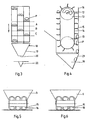
- Fig. 1 is a side elevation of a device according to the invention, comprising a planting element.
- Fig. 2 is a cross-sectional top plan view of the planting element of Fig. 1.
- Figs. 3 and 4 are a schematic front view and a schematic longitudinal sectional view of a planting element according to the invention.
- Figs. 5 and 6 are schematic, cross-sectional top plan views of two further embodiments of the planting element according to the invention.
- Fig. 1 shows an example of a planting machine 1 according to the invention, by means of which four rows of seed material, in this case potatoes P, for example, can be planted in one operation.
- the planting machine 1 comprises a frame 2, which can be coupled to a tractor (not shown) by means of a three-point linkage that is known per se, and which is furthermore supported by ground wheels 4.
- a storage hopper 5 for potatoes to be planted and four (substantially vertical) planting elements 6 are mounted on and in the frame 2, which planting elements are all provided with a delivery opening (indicated at 20 in Fig. 3) at their bottom sides.
- a planting coulter 7, also referred to as furrow or trench opener, is mounted under the frame, in front of each of said openings.
- the frame 2 further comprises parallelogram mechanisms 10, by means of which the planting depth can be adjusted and be maintained at the adjusted value.
- parallelogram mechanisms 10 by means of which the planting depth can be adjusted and be maintained at the adjusted value.
- Figs, 2-4 show different views of a planting element 6 as shown in Fig. 1, comprising a housing 11, two horizontal shafts 12, on which a drum 13 is mounted, and an endless belt 14, which is passed over the drums 13 and to which three vertical rows of cups 15 are attached.
- the lower drum 13 is driven proportionally to the speed of the planting machine 1 by means of a chain (not shown).
- the front side of each of the planting elements 6 is provided with three parallel semi-tubes 16, which surround the respective rows of cups 15. I.e., inherent to this configuration is the fact that the rows that lie side by side extend jointly in a direction transversely to the direction of movement of the planting machine 1.
- a funnel-shaped, symmetrical guide 18 is disposed centrally below the planting element 6, the width of said guide at the upper side thereof being greater than or equal to the width of the belt 14, and the side walls 19 of said guide tapering off in downward direction, terminating in a common delivery opening 20.
- the front wall 21 of the guide 18 slopes towards the rear. The angle of said sloping wall 21 is adjustable from vertical to e.g. 45° in rearward direction.
- the rear side of the belt 14 moves upwards, in such a manner that the cups 15 remove potatoes P from the storage hopper 5.
- the cups 15 move through the semi-tubes 16 at the front side of the planting elements 6.
- the potatoes fall from their respective cups 15 onto the preceding cups 15.
- the cups 15 are turned upside down once again and the potatoes are released one by one.
- the potatoes fall into the guide 18, roll towards the delivery opening 20 and fall in the trench 22 under said delivery opening.
- Fig. 3 shows the distances by which the cups 15 are spaced apart.
- the cups in one row are spaced a regular distance apart, which distance is the same for each row, viz. A+B+C, and preferably it is selected to be at least equal to or maximally 1.5 times larger than the distance that is used with the existing 2-cup belt (which is usually about 13 cm).
- the value lies approximately halfway this range, so that on the one hand a higher capacity is achieved, given the same speed of the cup belt, whilst on the other hand an improved filling of the cups is achieved, because the filling interval between two cups in the same row is greater.
- the potatoes from the two outer planting channels must be moved over a relatively large distance towards the middle after exiting the planting channels.
- the potatoes exiting the outer channels must cover a longer distance, therefore, and experience more resistance, i.e. the time of fall before they hit the bottom of the pre-formed trench is longer.
- the middle row of cups is offset with respect to the outer rows.
- the distance C between the cups 15 in the right-hand row and the next cups in the middle row is larger than the distance B between the cups 15 in said middle row and the next cups 15 in the left-hand row.
- said distances, C and B are larger and smaller, respectively, than the distance A between the cups 15 in the left-hand row and the next cups 15 in the right-hand row.
- FIG. 5 A comparable result is obtained with the embodiment that is shown in Fig. 5.
- the distances A, B and C between the cups 15 are identical, but the cups 15 in the middle row are longer than the cups 15 in the left-hand row and the right-hand row.
- the clearance between the cups 16 in the middle row and the respective semi-tube 16 will be large enough at a later moment to release the potato.
- the moment at which the potatoes in the middle row of cups 15 are released is delayed in that the diameter of the middle semi-tube 16 is smaller than the diameter of the left-hand tube 16 and the right-hand tube 16.
- At least the side walls 19, and possibly also the aforesaid sloping wall 21, are made of a flexible material. Suitable materials are, for example, gauze, cloth, either woven or nonwoven, and foil.
- the sloping wall 21 furthermore guides the potatoes in a rearward direction, i.e. in a direction opposed to the direction of movement of the planting machine. As a result, the forward speed of the planting machine is partially compensated and the potatoes will hit the ground at a lower speed.
- planting elements may comprise four or more rows of cups.
- an asymmetrical guide may be used, in which case the moment and/or the height at which the bulbs or tubers are released above the guide can be adapted to such a guide again.
Landscapes
- Life Sciences & Earth Sciences (AREA)
- Soil Sciences (AREA)
- Environmental Sciences (AREA)
- Sowing (AREA)
- Transplanting Machines (AREA)
- Medicines Containing Plant Substances (AREA)
Claims (11)
- Dispositif (1) pour planter des plantes à bulbe et à tubercule, en particulier des pommes de terre, comprenant une trémie de stockage (5) pour les bulbes ou les tubercules à planter, un transporteur (13, 14) comprenant des rangées parallèles d'éléments (15) destinés à recevoir des pommes de terre en provenance de la trémie de stockage (5) et à libérer de nouveau lesdites pommes de terre, et un guide (18) destiné à guider les bulbes ou tubercules libérés jusqu'à une ouverture de distribution commune (20), caractérisé en ce que le transporteur (13, 14) comprend au moins trois rangées de tels éléments (15) et en ce que le dispositif (1) est configuré de telle manière que les différences entre les temps de chute des bulbes ou tubercules provenant de différentes rangées soient compensées par des différences dans l'instant et/ou la hauteur auxquels les bulbes ou tubercules sont libérés au-dessus du guide (18).
- Dispositif (1) selon la revendication 1, dans lequel lesdites rangées d'éléments (15) sont décalées l'une par rapport à l'autre (A ≠ B ≠ C).
- Dispositif (1) selon la revendication 1 ou 2, qui est équipé d'un guide essentiellement symétrique et centré (18), dans lequel la distance (C) entre les éléments (15) dans une des rangées extérieures et les éléments suivants (15) dans au moins une des rangées intérieures est plus grande que la distance (B) entre les éléments (15) dans ladite rangée intérieure et les éléments suivants (15) dans l'autre rangée extérieure (C > B).
- Dispositif (1) selon la revendication 3, dans lequel la moyenne (B+C)/2 des distances précitées est essentiellement égale à la plus courte distance (A) entre les éléments (15) dans une rangée extérieure et ceux dans l'autre rangée extérieure.
- Dispositif selon l'une quelconque des revendications précédentes, dans lequel les éléments (15) destinés à recevoir des bulbes ou tubercules sont entourés de conduits (16) et dans lequel les éléments (15) dans les conduits (16) et/ou les conduits (16) associés à au moins deux rangées sont configurés de façon à être différents les uns des autres.
- Dispositif (1) selon la revendication 5, dans lequel les éléments (15) dans au moins une des rangées extérieures et/ou le diamètre d'au moins un des conduits (16) des rangées extérieures est (sont) configuré de manière à être plus petit ou plus grand que ceux de la rangée ou des rangées intérieures.
- Dispositif (1) selon l'une quelconque des revendications précédentes, dans lequel le transporteur (13, 14) comprend exactement trois rangées d'éléments (15).
- Dispositif (1) selon l'une quelconque des revendications précédentes, dans lequel ledit guide (18) comprend une matière flexible sous au moins une des rangées, de manière que, lorsqu'un bulbe ou tubercule entre en contact avec cette matière, le choc est absorbé et la pomme de terre glisse vers le bas.
- Dispositif (1) selon la revendication 8, dans lequel ladite matière comprend un tissu ou une feuille.
- Dispositif (1) selon l'une quelconque des revendications précédentes, dans lequel ledit guide (18) comprend une paroi inclinée (21) au moyen de laquelle les bulbes ou tubercules sont guidés vers une direction arrière, c'est-à-dire dans une direction opposée à la direction du mouvement du dispositif (1).
- Dispositif (1) selon la revendication 10, dans lequel l'angle de ladite paroi inclinée (21) est réglable.
Applications Claiming Priority (2)
| Application Number | Priority Date | Filing Date | Title |
|---|---|---|---|
| NL1025202A NL1025202C2 (nl) | 2004-01-09 | 2004-01-09 | Inrichting voor het poten van bol- en knolgewassen, in het bijzonder aardappels. |
| PCT/NL2005/000011 WO2005065441A1 (fr) | 2004-01-09 | 2005-01-10 | Dispositif permettant de planter des plantes a bulbe et des plantes a tubercule, en particulier des pommes de terre |
Publications (2)
| Publication Number | Publication Date |
|---|---|
| EP1701606A1 EP1701606A1 (fr) | 2006-09-20 |
| EP1701606B1 true EP1701606B1 (fr) | 2007-05-23 |
Family
ID=34748209
Family Applications (1)
| Application Number | Title | Priority Date | Filing Date |
|---|---|---|---|
| EP05704542A Not-in-force EP1701606B1 (fr) | 2004-01-09 | 2005-01-10 | Dispositif permettant de planter des plantes a bulbe et des plantes a tubercule, en particulier des pommes de terre |
Country Status (5)
| Country | Link |
|---|---|
| EP (1) | EP1701606B1 (fr) |
| AT (1) | ATE362697T1 (fr) |
| DE (1) | DE602005001195D1 (fr) |
| NL (1) | NL1025202C2 (fr) |
| WO (1) | WO2005065441A1 (fr) |
Families Citing this family (7)
| Publication number | Priority date | Publication date | Assignee | Title |
|---|---|---|---|---|
| US8850995B2 (en) | 2009-02-02 | 2014-10-07 | Deere & Company | Seeding machine with seed delivery system |
| US8671856B2 (en) | 2009-02-02 | 2014-03-18 | Deere & Company | Planting unit for a seeding machine having blocking member to control hand-off of seed from a seed meter to a seed delivery system |
| CN103843482A (zh) * | 2014-03-04 | 2014-06-11 | 青岛农业大学 | 用于马铃薯的多功能作业机组 |
| US11058047B2 (en) | 2018-06-27 | 2021-07-13 | Deere & Company | Seeding system |
| US11051445B2 (en) | 2018-06-27 | 2021-07-06 | Deere & Company | Seeding system |
| US11064649B2 (en) | 2018-06-27 | 2021-07-20 | Deere & Company | Seeding system |
| US11612100B2 (en) * | 2019-11-11 | 2023-03-28 | Rainer Borgmann | Converging row unit for potato planter |
Family Cites Families (5)
| Publication number | Priority date | Publication date | Assignee | Title |
|---|---|---|---|---|
| DE817660C (de) * | 1948-08-24 | 1951-10-18 | Charles Barnett | Kartoffelpflanzmaschine |
| GB681315A (en) * | 1949-07-07 | 1952-10-22 | Johannes Jacobus De Villiers S | Improved planter for potatoes and other tubers or seeds |
| DE1954171C3 (de) * | 1969-10-28 | 1974-10-10 | Scheer Geb. Hupe, Paula, 4509 Bad Essen | Selbsttätige Kartoffellegemaschine |
| DE9401110U1 (de) | 1994-01-24 | 1994-05-11 | Gruse August Maschf Gmbh | Maschine zum Legen von Kartoffeln in Beeten |
| NL1014692C2 (nl) | 2000-03-20 | 2001-09-25 | Netagco Potato Division B V | Inrichting voor het poten van aardappelen. |
-
2004
- 2004-01-09 NL NL1025202A patent/NL1025202C2/nl not_active IP Right Cessation
-
2005
- 2005-01-10 AT AT05704542T patent/ATE362697T1/de not_active IP Right Cessation
- 2005-01-10 DE DE602005001195T patent/DE602005001195D1/de active Active
- 2005-01-10 EP EP05704542A patent/EP1701606B1/fr not_active Not-in-force
- 2005-01-10 WO PCT/NL2005/000011 patent/WO2005065441A1/fr active IP Right Grant
Also Published As
| Publication number | Publication date |
|---|---|
| DE602005001195D1 (de) | 2007-07-05 |
| NL1025202C2 (nl) | 2005-07-12 |
| WO2005065441A1 (fr) | 2005-07-21 |
| EP1701606A1 (fr) | 2006-09-20 |
| ATE362697T1 (de) | 2007-06-15 |
Similar Documents
| Publication | Publication Date | Title |
|---|---|---|
| EP1701606B1 (fr) | Dispositif permettant de planter des plantes a bulbe et des plantes a tubercule, en particulier des pommes de terre | |
| AU2009230784B2 (en) | Planter with cup belt meter | |
| UA127394C2 (uk) | Вузол для видачі зерноподібних продуктів | |
| US4023509A (en) | Apparatus for planting a plurality of individual seeds in a planting furrow | |
| CA2816747C (fr) | Procede pour planter des patates a haute vitesse et equipement permettant l'execution dudit procede | |
| US6173664B1 (en) | Equidistant planting system | |
| US9743577B1 (en) | Planter for rhizomes and the like | |
| US3122283A (en) | Row crop seed planter | |
| EP3056073A1 (fr) | Planteuse | |
| KR20160148273A (ko) | 스마트 종자파종기 | |
| KR100895093B1 (ko) | 다용도 씨앗 파종기 | |
| IE55637B1 (en) | Transplanter provided with seedlings selector | |
| KR101919004B1 (ko) | 마늘종구 발근부 하향 직립 파종기 | |
| JP4820082B2 (ja) | 播種機 | |
| US1951003A (en) | Planter | |
| EP0515411B1 (fr) | Dispositif pour planter les pommes de terre | |
| JP4370671B2 (ja) | 苗移植機 | |
| RU67814U1 (ru) | Сеялка | |
| JP2000209909A (ja) | 苗移植機 | |
| RU2393663C1 (ru) | Картофелесажалка для посадки проращенных клубней | |
| RU2655754C1 (ru) | Сажалка предварительно проращенного картофеля | |
| KR101945853B1 (ko) | 고구마 정식기 및 이의 구동 방법 | |
| JPH0337376Y2 (fr) | ||
| JP6720782B2 (ja) | 混植苗の作成方法 | |
| JP3536156B2 (ja) | 移植機 |
Legal Events
| Date | Code | Title | Description |
|---|---|---|---|
| PUAI | Public reference made under article 153(3) epc to a published international application that has entered the european phase |
Free format text: ORIGINAL CODE: 0009012 |
|
| 17P | Request for examination filed |
Effective date: 20060630 |
|
| AK | Designated contracting states |
Kind code of ref document: A1 Designated state(s): AT BE BG CH CY CZ DE DK EE ES FI FR GB GR HU IE IS IT LI LT LU MC NL PL PT RO SE SI SK TR |
|
| GRAP | Despatch of communication of intention to grant a patent |
Free format text: ORIGINAL CODE: EPIDOSNIGR1 |
|
| GRAS | Grant fee paid |
Free format text: ORIGINAL CODE: EPIDOSNIGR3 |
|
| DAX | Request for extension of the european patent (deleted) | ||
| GRAA | (expected) grant |
Free format text: ORIGINAL CODE: 0009210 |
|
| AK | Designated contracting states |
Kind code of ref document: B1 Designated state(s): AT BE BG CH CY CZ DE DK EE ES FI FR GB GR HU IE IS IT LI LT LU MC NL PL PT RO SE SI SK TR |
|
| PG25 | Lapsed in a contracting state [announced via postgrant information from national office to epo] |
Ref country code: LI Free format text: LAPSE BECAUSE OF FAILURE TO SUBMIT A TRANSLATION OF THE DESCRIPTION OR TO PAY THE FEE WITHIN THE PRESCRIBED TIME-LIMIT Effective date: 20070523 Ref country code: FI Free format text: LAPSE BECAUSE OF FAILURE TO SUBMIT A TRANSLATION OF THE DESCRIPTION OR TO PAY THE FEE WITHIN THE PRESCRIBED TIME-LIMIT Effective date: 20070523 Ref country code: CH Free format text: LAPSE BECAUSE OF FAILURE TO SUBMIT A TRANSLATION OF THE DESCRIPTION OR TO PAY THE FEE WITHIN THE PRESCRIBED TIME-LIMIT Effective date: 20070523 |
|
| REG | Reference to a national code |
Ref country code: GB Ref legal event code: FG4D |
|
| REG | Reference to a national code |
Ref country code: CH Ref legal event code: EP |
|
| REG | Reference to a national code |
Ref country code: IE Ref legal event code: FG4D |
|
| REF | Corresponds to: |
Ref document number: 602005001195 Country of ref document: DE Date of ref document: 20070705 Kind code of ref document: P |
|
| PG25 | Lapsed in a contracting state [announced via postgrant information from national office to epo] |
Ref country code: SE Free format text: LAPSE BECAUSE OF FAILURE TO SUBMIT A TRANSLATION OF THE DESCRIPTION OR TO PAY THE FEE WITHIN THE PRESCRIBED TIME-LIMIT Effective date: 20070823 |
|
| PG25 | Lapsed in a contracting state [announced via postgrant information from national office to epo] |
Ref country code: ES Free format text: LAPSE BECAUSE OF FAILURE TO SUBMIT A TRANSLATION OF THE DESCRIPTION OR TO PAY THE FEE WITHIN THE PRESCRIBED TIME-LIMIT Effective date: 20070903 |
|
| PG25 | Lapsed in a contracting state [announced via postgrant information from national office to epo] |
Ref country code: IS Free format text: LAPSE BECAUSE OF FAILURE TO SUBMIT A TRANSLATION OF THE DESCRIPTION OR TO PAY THE FEE WITHIN THE PRESCRIBED TIME-LIMIT Effective date: 20070923 |
|
| NLV1 | Nl: lapsed or annulled due to failure to fulfill the requirements of art. 29p and 29m of the patents act | ||
| PG25 | Lapsed in a contracting state [announced via postgrant information from national office to epo] |
Ref country code: PL Free format text: LAPSE BECAUSE OF FAILURE TO SUBMIT A TRANSLATION OF THE DESCRIPTION OR TO PAY THE FEE WITHIN THE PRESCRIBED TIME-LIMIT Effective date: 20070523 Ref country code: AT Free format text: LAPSE BECAUSE OF FAILURE TO SUBMIT A TRANSLATION OF THE DESCRIPTION OR TO PAY THE FEE WITHIN THE PRESCRIBED TIME-LIMIT Effective date: 20070523 |
|
| REG | Reference to a national code |
Ref country code: CH Ref legal event code: PL |
|
| PG25 | Lapsed in a contracting state [announced via postgrant information from national office to epo] |
Ref country code: BE Free format text: LAPSE BECAUSE OF FAILURE TO SUBMIT A TRANSLATION OF THE DESCRIPTION OR TO PAY THE FEE WITHIN THE PRESCRIBED TIME-LIMIT Effective date: 20070523 |
|
| EN | Fr: translation not filed | ||
| PG25 | Lapsed in a contracting state [announced via postgrant information from national office to epo] |
Ref country code: SI Free format text: LAPSE BECAUSE OF FAILURE TO SUBMIT A TRANSLATION OF THE DESCRIPTION OR TO PAY THE FEE WITHIN THE PRESCRIBED TIME-LIMIT Effective date: 20070523 Ref country code: NL Free format text: LAPSE BECAUSE OF FAILURE TO SUBMIT A TRANSLATION OF THE DESCRIPTION OR TO PAY THE FEE WITHIN THE PRESCRIBED TIME-LIMIT Effective date: 20070523 Ref country code: DK Free format text: LAPSE BECAUSE OF FAILURE TO SUBMIT A TRANSLATION OF THE DESCRIPTION OR TO PAY THE FEE WITHIN THE PRESCRIBED TIME-LIMIT Effective date: 20070523 Ref country code: BG Free format text: LAPSE BECAUSE OF FAILURE TO SUBMIT A TRANSLATION OF THE DESCRIPTION OR TO PAY THE FEE WITHIN THE PRESCRIBED TIME-LIMIT Effective date: 20070823 Ref country code: CZ Free format text: LAPSE BECAUSE OF FAILURE TO SUBMIT A TRANSLATION OF THE DESCRIPTION OR TO PAY THE FEE WITHIN THE PRESCRIBED TIME-LIMIT Effective date: 20070523 |
|
| PG25 | Lapsed in a contracting state [announced via postgrant information from national office to epo] |
Ref country code: LT Free format text: LAPSE BECAUSE OF FAILURE TO SUBMIT A TRANSLATION OF THE DESCRIPTION OR TO PAY THE FEE WITHIN THE PRESCRIBED TIME-LIMIT Effective date: 20070523 Ref country code: SK Free format text: LAPSE BECAUSE OF FAILURE TO SUBMIT A TRANSLATION OF THE DESCRIPTION OR TO PAY THE FEE WITHIN THE PRESCRIBED TIME-LIMIT Effective date: 20070523 |
|
| PLBE | No opposition filed within time limit |
Free format text: ORIGINAL CODE: 0009261 |
|
| STAA | Information on the status of an ep patent application or granted ep patent |
Free format text: STATUS: NO OPPOSITION FILED WITHIN TIME LIMIT |
|
| 26N | No opposition filed |
Effective date: 20080226 |
|
| PG25 | Lapsed in a contracting state [announced via postgrant information from national office to epo] |
Ref country code: DE Free format text: LAPSE BECAUSE OF FAILURE TO SUBMIT A TRANSLATION OF THE DESCRIPTION OR TO PAY THE FEE WITHIN THE PRESCRIBED TIME-LIMIT Effective date: 20070824 Ref country code: GR Free format text: LAPSE BECAUSE OF FAILURE TO SUBMIT A TRANSLATION OF THE DESCRIPTION OR TO PAY THE FEE WITHIN THE PRESCRIBED TIME-LIMIT Effective date: 20070824 Ref country code: IT Free format text: LAPSE BECAUSE OF FAILURE TO SUBMIT A TRANSLATION OF THE DESCRIPTION OR TO PAY THE FEE WITHIN THE PRESCRIBED TIME-LIMIT Effective date: 20070523 |
|
| PG25 | Lapsed in a contracting state [announced via postgrant information from national office to epo] |
Ref country code: RO Free format text: LAPSE BECAUSE OF FAILURE TO SUBMIT A TRANSLATION OF THE DESCRIPTION OR TO PAY THE FEE WITHIN THE PRESCRIBED TIME-LIMIT Effective date: 20070523 |
|
| PG25 | Lapsed in a contracting state [announced via postgrant information from national office to epo] |
Ref country code: FR Free format text: LAPSE BECAUSE OF FAILURE TO SUBMIT A TRANSLATION OF THE DESCRIPTION OR TO PAY THE FEE WITHIN THE PRESCRIBED TIME-LIMIT Effective date: 20080118 |
|
| PG25 | Lapsed in a contracting state [announced via postgrant information from national office to epo] |
Ref country code: MC Free format text: LAPSE BECAUSE OF NON-PAYMENT OF DUE FEES Effective date: 20080131 |
|
| PG25 | Lapsed in a contracting state [announced via postgrant information from national office to epo] |
Ref country code: EE Free format text: LAPSE BECAUSE OF FAILURE TO SUBMIT A TRANSLATION OF THE DESCRIPTION OR TO PAY THE FEE WITHIN THE PRESCRIBED TIME-LIMIT Effective date: 20070523 Ref country code: IE Free format text: LAPSE BECAUSE OF NON-PAYMENT OF DUE FEES Effective date: 20080110 |
|
| PG25 | Lapsed in a contracting state [announced via postgrant information from national office to epo] |
Ref country code: CY Free format text: LAPSE BECAUSE OF FAILURE TO SUBMIT A TRANSLATION OF THE DESCRIPTION OR TO PAY THE FEE WITHIN THE PRESCRIBED TIME-LIMIT Effective date: 20070523 |
|
| GBPC | Gb: european patent ceased through non-payment of renewal fee |
Effective date: 20090110 |
|
| PG25 | Lapsed in a contracting state [announced via postgrant information from national office to epo] |
Ref country code: GB Free format text: LAPSE BECAUSE OF NON-PAYMENT OF DUE FEES Effective date: 20090110 |
|
| PG25 | Lapsed in a contracting state [announced via postgrant information from national office to epo] |
Ref country code: HU Free format text: LAPSE BECAUSE OF FAILURE TO SUBMIT A TRANSLATION OF THE DESCRIPTION OR TO PAY THE FEE WITHIN THE PRESCRIBED TIME-LIMIT Effective date: 20071124 Ref country code: LU Free format text: LAPSE BECAUSE OF NON-PAYMENT OF DUE FEES Effective date: 20080110 |
|
| PG25 | Lapsed in a contracting state [announced via postgrant information from national office to epo] |
Ref country code: TR Free format text: LAPSE BECAUSE OF FAILURE TO SUBMIT A TRANSLATION OF THE DESCRIPTION OR TO PAY THE FEE WITHIN THE PRESCRIBED TIME-LIMIT Effective date: 20070523 |
|
| PG25 | Lapsed in a contracting state [announced via postgrant information from national office to epo] |
Ref country code: PT Free format text: LAPSE BECAUSE OF FAILURE TO SUBMIT A TRANSLATION OF THE DESCRIPTION OR TO PAY THE FEE WITHIN THE PRESCRIBED TIME-LIMIT Effective date: 20070523 |