EP1698412B1 - Vorrichtung zur steuerung der menge einer gegossenen metallschmelze - Google Patents
Vorrichtung zur steuerung der menge einer gegossenen metallschmelze Download PDFInfo
- Publication number
- EP1698412B1 EP1698412B1 EP04807428.0A EP04807428A EP1698412B1 EP 1698412 B1 EP1698412 B1 EP 1698412B1 EP 04807428 A EP04807428 A EP 04807428A EP 1698412 B1 EP1698412 B1 EP 1698412B1
- Authority
- EP
- European Patent Office
- Prior art keywords
- molten metal
- plate brick
- control device
- quantity control
- brick
- Prior art date
- Legal status (The legal status is an assumption and is not a legal conclusion. Google has not performed a legal analysis and makes no representation as to the accuracy of the status listed.)
- Not-in-force
Links
Images


Classifications
-
- B—PERFORMING OPERATIONS; TRANSPORTING
- B22—CASTING; POWDER METALLURGY
- B22D—CASTING OF METALS; CASTING OF OTHER SUBSTANCES BY THE SAME PROCESSES OR DEVICES
- B22D41/00—Casting melt-holding vessels, e.g. ladles, tundishes, cups or the like
- B22D41/14—Closures
- B22D41/22—Closures sliding-gate type, i.e. having a fixed plate and a movable plate in sliding contact with each other for selective registry of their openings
- B22D41/26—Closures sliding-gate type, i.e. having a fixed plate and a movable plate in sliding contact with each other for selective registry of their openings characterised by a rotatively movable plate
-
- B—PERFORMING OPERATIONS; TRANSPORTING
- B22—CASTING; POWDER METALLURGY
- B22D—CASTING OF METALS; CASTING OF OTHER SUBSTANCES BY THE SAME PROCESSES OR DEVICES
- B22D41/00—Casting melt-holding vessels, e.g. ladles, tundishes, cups or the like
- B22D41/14—Closures
- B22D41/22—Closures sliding-gate type, i.e. having a fixed plate and a movable plate in sliding contact with each other for selective registry of their openings
- B22D41/28—Plates therefor
- B22D41/34—Supporting, fixing or centering means therefor
-
- B—PERFORMING OPERATIONS; TRANSPORTING
- B22—CASTING; POWDER METALLURGY
- B22D—CASTING OF METALS; CASTING OF OTHER SUBSTANCES BY THE SAME PROCESSES OR DEVICES
- B22D41/00—Casting melt-holding vessels, e.g. ladles, tundishes, cups or the like
- B22D41/14—Closures
- B22D41/22—Closures sliding-gate type, i.e. having a fixed plate and a movable plate in sliding contact with each other for selective registry of their openings
- B22D41/38—Means for operating the sliding gate
-
- C—CHEMISTRY; METALLURGY
- C21—METALLURGY OF IRON
- C21C—PROCESSING OF PIG-IRON, e.g. REFINING, MANUFACTURE OF WROUGHT-IRON OR STEEL; TREATMENT IN MOLTEN STATE OF FERROUS ALLOYS
- C21C5/00—Manufacture of carbon-steel, e.g. plain mild steel, medium carbon steel or cast steel or stainless steel
- C21C5/28—Manufacture of steel in the converter
- C21C5/42—Constructional features of converters
- C21C5/46—Details or accessories
- C21C5/4653—Tapholes; Opening or plugging thereof
-
- C—CHEMISTRY; METALLURGY
- C21—METALLURGY OF IRON
- C21C—PROCESSING OF PIG-IRON, e.g. REFINING, MANUFACTURE OF WROUGHT-IRON OR STEEL; TREATMENT IN MOLTEN STATE OF FERROUS ALLOYS
- C21C5/00—Manufacture of carbon-steel, e.g. plain mild steel, medium carbon steel or cast steel or stainless steel
- C21C5/28—Manufacture of steel in the converter
- C21C5/42—Constructional features of converters
- C21C5/46—Details or accessories
- C21C5/4673—Measuring and sampling devices
-
- F—MECHANICAL ENGINEERING; LIGHTING; HEATING; WEAPONS; BLASTING
- F27—FURNACES; KILNS; OVENS; RETORTS
- F27D—DETAILS OR ACCESSORIES OF FURNACES, KILNS, OVENS, OR RETORTS, IN SO FAR AS THEY ARE OF KINDS OCCURRING IN MORE THAN ONE KIND OF FURNACE
- F27D3/00—Charging; Discharging; Manipulation of charge
- F27D3/15—Tapping equipment; Equipment for removing or retaining slag
- F27D3/1509—Tapping equipment
- F27D3/1518—Tapholes
Definitions
- the present invention relates to a poured molten metal quantity control device mounted on the bottom of a molten metal vessel such as a ladle and a tundish to control the pouring feed rate of the molten metal by sliding a slide plate brick to adjust the relative degree of opening of a pouring port thereof to a pouring port of a fixed plate brick.
- a poured molten metal quantity control device ordinarily includes a fixed plate, which has a pouring port and is composed of a refractory detachably mounted on a base plate fixed to a ladle and the like, and a slide plate, which has a pouring port and is composed of a refractory detachably mounted on a slide frame, and controls the pouring feed rate of the molten metal by adjusting the degree of opening between the pouring port of the fixed plate and the pouring port of the slide plate by a slide system for linearly sliding the slide plate along the base plate.
- a metal slide system and a roller slide system are available as the slide system of the slide frame in the poured molten metal quantity control device employing the linear slide system, and the basic structure of the metal slide system is widely known and used from the beginning of development of this type of apparatuses to the present (refer to, for example, patent documents 1 and 2).
- the metal slide system since a slide plate is pressed against a fixed plate through a slide frame by a hydraulic cylinder and the like to thereby linearly move the slide plate, the metal slide system is advantageous in that the positions at which the degree of opening of a pouring port is completely opened or closed can be obtained with relatively high accuracy.
- drive force larger than the sum of the friction force generated on the slide surface between the fixed plate and the slide plate and the friction force generated on the slide surface between the slide frame and a guide member thereof.
- the slide frame and the guide member thereof since the slide frame and the guide member thereof are worn, they must be replaced, for example, about every 500 heats.
- the roller slide system is developed to overcome the problem of friction force in the metal slide system described above (refer to, for example, patent document 3).
- the roller slide system can reduce the friction force generated at the time when a slide plate is slid, by using a roller, and further can reduce apparatus cost and maintenance cost.
- the point of action of the roller to the periphery of a pouring port of the slide plate shifts and thus press force exerted to the periphery of the pouring port lacks balance, from which a possibility arises in that the press force is reduced on the periphery of the pouring port.
- a rotary type poured molten metal quantity control device which relatively changes respective pouring ports from a completely open position to a completely close position by slidingly turning a slide plate brick with respect to a fixed plate brick.
- the rotary type poured molten metal quantity control device is advantageous in that it is comparatively compact because a worm device and the like are used as a means for turning a slide plate brick in contrast that the linear slide type poured molten metal quantity control device requires an additional expansion length corresponding to the stroke of the slide plate, press force is exerted in relatively good balance, the maintenance of device is easy, and total cost can be reduced because of the extended life of a refractory.
- many small to large rotary type poured molten metal quantity control devices are used as poured molten metal quantity control devices (refer to patent document 4).
- Fig. 9 is a view showing an example of a conventional rotary type poured molten metal quantity control device that controls a pouring feed rate by controlling the degrees of opening of a pouring port of a fixed plate brick 20 and a pouring port of a slide plate brick 50 from a completely open position to a completely close position by the sliding turn angle of the slide plate brick 50 that slidingly turns in contact with the fixed plate brick 20.
- the turning operation is executed by a worm 90 and a worm gear 91 coupled with a frame 70 for supporting the slide plate brick 50.
- Fig. 10 is a view showing an example of a conventional linear slide type poured molten metal quantity control device.
- the conventional poured molten metal quantity control device controls a pouring feed rate by controlling the degrees of opening of a pouring port of a fixed plate brick 200 and a pouring port of a slide plate brick 500 from a completely open position to a completely close position by the slide amount of the slide plate brick 500 that linearly slides in contact with the fixed plate brick 200 fixed to a base plate 100.
- the sliding operation is executed by a rod stroke of a hydraulic cylinder 900.
- the linear slide type poured molten metal quantity control device is advantageous in that since operation start and end positions can be firmly determined by the rod stroke, a control can be securely carried out by matching the completely open/close positions of the pouring ports to the operation start and end positions.
- a coupling portion 910 between the hydraulic cylinder 900 and a support portion 700 of the slide plate brick 500 must be made in a separable type, and a trouble job for separating the coupling portion 910 must be executed each time the brick is reversed.
- this job is indispensable in any of the slide system and the rotary system.
- a poured molten metal quantity control device used in a rotary pouring apparatus comprises the following items (1) - (5):
- a door when a brick position reverse job is carried out in a door type poured molten metal quantity control device, a door can be opened a closed irrespectively of a turn system. Further, the completely open/close positions of the pouring ports can be fixed to the relative positions of the end and start positions of the stroke of the extendable unit.
- a poured molten metal quantity control device of the present invention is arranged such as claimed in dependent claims 2-9. That is, a unit member of a conventionally used poured molten metal quantity control device can be easily reused, and an extendable unit having a more proper and small capacity can be selected by properly selecting the respective pivot positions.
- a best mode for embodying the present invention has the following structure to make a reversing job easily which is carried out to dislocate the position of a fixed plate brick and a slide plate brick that are worn mainly in a pouring port portion as well as to securely and easily obtain the complete open/close positions of a pouring port. More specifically, the structure is arranged such that:
- 1 denotes a base plate
- 2 denotes a fixed brick
- 3 denotes a fixed plate
- 4 denotes an outer race
- 5 denotes a slide plate brick
- 6 denotes a slide plate case
- 7 denotes a frame
- 8 denotes a hydraulic cylinder
- 9 denoted a cylinder pivot portion.
- a poured molten metal quantity control device is mounted on the bottom and the like of a molten metal vessel by a base plate 1, and is equipped with an outer race 4 which is fitted around and engaged with the outer periphery of a fixed plate 3, that is fixed to the base plate 1 for supporting a fixed plate brick 2, so as to be rotatable by the hydraulic cylinder 8, and with a frame 7 which is engaged with a hinge portion 42 fixed to the outer race 4.
- the frame 7 is provided with the slide plate brick 5, which turns in sliding contact with the surface of the fixed plate brick 1, and with the slide plate case 6 for supporting the slide plate brick 5 in the frame.
- the hydraulic cylinder 8 is engaged with a coupling end portion 82 disposed at the end of a cylinder rod 81 of the hydraulic cylinder 8 through a pivot in a coupling portion 41 disposed to the outer race. Further, the hydraulic cylinder 8 is engaged with a cylinder pivot 9 for externally supporting the hydraulic cylinder 8 so that it can be moved pivotally.
- a link mechanism is arranged which uses three points as contact points, that is, an engagement pin P2, which engages the coupling portion 41 with the coupling end portion 82, a support pivot P1 at the engagement portion of the cylinder pivot portion 9 with the hydraulic cylinder 8, and the center of turn P3 of the outer lace 4 and which uses the distance H between P1 and P3, the radius of turn of the outer lace 4 (distance between P2 and P3) R, and the distance Lx between P1 and P2 created by the rod stroke of the hydraulic cylinder as three link elements.
- the coupling end portion 82 of the hydraulic cylinder 8 is coupled only with the outer race 4 and is not directly coupled with the frame 7 in which the slide plate brick 5 is accommodated.
- the frame 7 can be pivotally released from the outer race 4 through the hinge portion 42 without being disconnected from the hydraulic cylinder, thereby the positions of the fixed plate brick 2 and the slide plate brick 5 that are worn can be easily reversed.
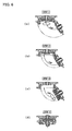
- Fig. 5 is an explanatory view explaining steps of reversing the positions of the fixed plate brick 2 and the slide plate brick 5.
- Fig. 5(a) shows STEP 1
- Fig. 2 shows STEP 2.
- STEP 1 (1) the frame 7 is opened up to 120° after a lock nut of a clamp for fixing the frame 7 is loosened, and then (2) after the slide plate brick 5 and the fixed brick 2 are removed, the positions thereof are reversed and then they are mounted again.
- a door (frame 7) is closed.
- the lower surface of an upper nozzle brick having a 50 ⁇ pouring port coupled with the bottom of the molten metal vessel is fixed to the fixed plate brick 2 in contact therewith, with the respective pouring ports concentrically disposed.
- the upper surface of a collector nozzle brick which has a 50 ⁇ pouring port for pouring molten metal to a ladle and the like, is fixed to the lower surface of the slide plate brick 5 in contact therewith, with the respective pouring ports concentrically disposed.
- a job for intermittently pouring molten cast iron of 1550°C was carried out 100 times by the poured molten metal quantity control device of the embodiment. The job was carried out at a cycle of 1.5 min/cycle. Further, after the intermittent pouring job was carried out 100 times, the door (frame 7) was opened through the hinge, a job for observing the surface state of the fixed plate brick 2 and the slide plate brick 5 and reversing and mounting the respective bricks was carried out.
- Fig. 3 is a schematic view showing a structure of a double door type in an embodiment 2 of the present invention, wherein Fig. 3(a) is a view observed from a pouring side, and Fig. 3(b) is a view observed from a side surface.
- Fig. 4 is an explanatory view schematically showing a structure of the embodiment 1.
- 61 denotes a slide plate hinge portion. Note that the same components as those shown in Figs. 1 and 2 of the embodiment 1 are denoted by the same reference numerals and the description thereof is omitted.
- the embodiment is different from the embodiment 1 in that a slide plate 6, in which a slide plate brick 5 is accommodated, is also pivotally opened and closed independently with respect to a frame 7 through a hinge portion 42 likewise the frame 7 to easily carry out a job for reversing and mounting the slide plate brick 5.
- a fixed plate 3 as a fixed plate brick receiver is provided which can be turned with respect to an outer race 4 for accommodating a fixed plate brick which is fixed to the base plate in the embodiment 1 so that it can be pivotally opened and closed through a hinge.
- the axial centers of all the hinges are disposed on the same axis.
- Fig. 6 is an explanatory view explaining steps of reversing the positions of a fixed plate brick 2 and the slide plate brick 5.
- Figs. 6(a) - (d) show respective STEPS 1 - 4.
- a poured molten metal quantity control device that can easily reverse the positions of the fixed plate brick 2 and the slide plate brick 5 at the time when they are worn, while secure and smooth control of the opening/closing of the pouring ports executed by the hydraulic cylinder as shown in the embodiment 1 is preserved.
- a ratio k value between the axial output F of the hydraulic cylinder and the turn torque T of the turn system is calculated with respect to the turn angle ⁇ of the turn system in the embodiments 1 and 2.
- Fig. 8 is a view showing a result of an actual measurement in which the turn torque T in the embodiment 1 was actually measured using the turn angle ⁇ as a parameter.
- the initial value of the turn torque at the start from a completely closed pouring port was about 8.2 KN ⁇ m, and a necessary torque in the range of the turn angle 90°, which was necessary until the pouring port was completely opened, was approximately constant and about 2.7 KN ⁇ m. Further, the initial value of torque at the start from a completely open pouring port was dispersed from about 4 to 8 KN ⁇ m, and a necessary torque was approximately constant and about 2.5 KN ⁇ m in the range of the turn angle of 90° until the turn system was turned and stopped in a completely closed state.
- a torque of 90% of the K value is generated at the start position of the turn torque. That is, it can be found that the hydraulic cylinder can make an effective selection by selecting and arranging the position P1, H, R, and L to set the turn angle ⁇ such that the maximum value of the K value or at least 90% of the K value is generated at the start position of the turn torque.
- a feature of the embodiments resides in that the rod stroke 0 position of the hydraulic cylinder 8 is matched to the completely open position of the pouring port. Accordingly, the terminate position obtained by completely closing the pouring port is matched to the entire length position of the rod stroke of the hydraulic cylinder 8. Since the initial state (position of rod stroke 0) of the hydraulic cylinder 8 must be matched to the pouring port completely open position in a traditional method of use of the hydraulic cylinder 8, it may be said this is an inverse use to the traditional method of use.
- the embodiments are characterized in that safety and maintainability are given precedence. More specifically, the embodiments intend to abruptly stop a pouring operation at the time when emergency occurs during the pouring operation of molten metal, and to prevent the operation of the hydraulic cylinder 8 to close the pouring port from being disturbed by the droplets of molten metal which have been deposited on the rod of the hydraulic cylinder 8 during the pouring operation at the completely open position of the pouring port. That is, the embodiments are characterized in that the initial state (position of rod stroke 0) of the hydraulic cylinder 8 is matched to the completely open position of the pouring port.
- the completely open position of the pouring port can be matched to the entire length state of the stroke of the hydraulic cylinder 8.
- an output corresponding to the area of the rod of the hydraulic cylinder 8 must be increased, and further a countermeasure such as a cover for droplets is required.
- the poured molten metal quantity control device can be used to control the pouring feed rate of not only molten steel but also light metal such as aluminum alloy, etc. and synthetic resin, etc., as well as a fluid such as paint, sludge, and the like.
Landscapes
- Engineering & Computer Science (AREA)
- Mechanical Engineering (AREA)
- Chemical & Material Sciences (AREA)
- Manufacturing & Machinery (AREA)
- Materials Engineering (AREA)
- Metallurgy (AREA)
- Organic Chemistry (AREA)
- General Engineering & Computer Science (AREA)
- Casting Support Devices, Ladles, And Melt Control Thereby (AREA)
Claims (9)
- Vorrichtung zur Steuerung der Menge einer gegossenen Metallschmelze, die in einer Drehgusseinrichtung verwendet wird, umfassend die folgenden Punkte 1) - 5):1) eine feste Steinplatte (2), die am Boden eines Metallschmelzengefäßes durch eine Grundplatte (1) montiert ist und mindestens eine Gießöffnung aufweist;2) einen Kollektorlochstein, der der festen Steinplatte mit einer konzentrisch gelegenen Gießöffnung gegenüber angeordnet ist;3) eine Schiebersteinplatte (5), die so zwischen dem Kollektorlochstein und der damit in Kontakt stehenden festen Steinplatte eingeschoben ist, dass sie sich gleitend auf den Gleitflächen des Kollektorlochsteins und der festen Steinplatte dreht, und mindestens eine Gießöffnung aufweist;4) einen Rahmen (7), an dem die Schiebersteinplatte (5) montiert ist;5) einen Außenring (4), der so an der Außenumfangsseite der festen Steinplatte (2) montiert ist, dass er von einer ausziehbaren Einheit (8) gedreht werden kann,wobei die Vorrichtung die Gießmenge der Metallschmelze steuert, indem sie die entsprechend offene Position der Gießöffnung der Schiebersteinplatte (5) und der Gießöffnung der festen Steinplatte (2) durch Drehen des Außenrings (4) mit der ausziehbaren Einheit (8) einstellt,
dadurch gekennzeichnet, dass der Rahmen (7) durch ein Zapfengelenk (42) so an dem Außenring (4) befestigt ist, dass er zu einer Öffnungs- und Schließbewegung an dem Zapfengelenk (42) unabhängig von der Dreheinrichtung des Außenrings (4) mit der ausziehbaren Einheit (8) fähig ist,
dass der Außenring (4) von einem Kurbelmechanismus unter Verwendung von Dreieckspunkten, bestehend aus einem Lagerdrehpunkt (P1) zum Lagern der ausziehbaren Einheit (8), der Drehachse (P3) des Außenrings (4) und einem Drehpunkt (P2), der in Eingriff mit einem Ende einer Teleskopstange (81) der ausziehbaren Einheit (8) ist und am Außenumfangsabschnitt des Außenrings (4) angeordnet ist, gedreht wird,
dass der Hub der ausziehbaren Einheit (8) und die Position des Lagerdrehpunktes (P1) der ausziehbaren Einheit (8) so gewählt werden, dass sie zu einer vollständig geöffneten Position (A), in der sich die Gießöffnung der Schiebersteinplatte mit der Gießöffnung der festen Steinplatte deckt, was eine Endposition bildet, und einer vollständig geschlossenen Stoppposition (B), die um einen vorbestimmten Winkel schräg versetzt zu der Endposition ist, führen, was eine Startposition bildet, so dass eine Drehstoppposition dem Drehwinkel (θo) zwischen der vollständig geöffneten Position (A) und der vollständig geschlossenen Position (B) in Bezug auf den Gesamthub (Lc) der ausziehbaren Einheit (8) entspricht,
und dass die Position des Lagerdrehpunktes (P1), der Abstand (H) zwischen dem Lagerdrehpunkt (P1) und der Drehachse (P3), der Drehradius (R) des Außenrings (4) und der Stangenhub (Lx) der ausziehbaren Einheit (8) so gewählt werden, dass der Drehwinkel (θ) auf die Startposition des Drehmoments eingestellt wird, wodurch mindestens 90 % des Höchstwertes des Verhältnisses (K) einer Teilkraft (T), die für das Drehmoment effektiv ist, zu dem axialen Ausstoß (F) der ausziehbaren Einheit (8) erzeugt werden. - Vorrichtung zur Steuerung der Menge einer gegossenen Metallschmelze nach Anspruch 1, dadurch gekennzeichnet, dass die ausziehbare Einheit (8) eine hydraulische oder pneumatische Zylindereinheit ist.
- Vorrichtung zur Steuerung der Menge einer gegossenen Metallschmelze nach Anspruch 1, dadurch gekennzeichnet, dass die ausziehbare Einheit (8) eine Schraubeinheit ist.
- Vorrichtung zur Steuerung der Menge einer gegossenen Metallschmelze nach Anspruch 1, dadurch gekennzeichnet, dass die ausziehbare Einheit (8) eine Zahnstangenritzel-Einheit ist.
- Vorrichtung zur Steuerung der Menge einer gegossenen Metallschmelze nach einem der Ansprüche 1 bis 4, dadurch gekennzeichnet, dass die Endposition und die Startposition jeweils dem Hub 0 und den Volllängenpositionen der Teleskopstange (81) der ausziehbaren Einheit (8) entsprechen.
- Vorrichtung zur Steuerung der Menge einer gegossenen Metallschmelze nach einem der Ansprüche 1 bis 5, dadurch gekennzeichnet, dass der Drehwinkel θ zwischen dem Drehradius der Startposition und der Achse, die sich gleichermaßen zwischen dem Lagerdrehpunkt (P1) und dem Drehpunkt (P2) erstreckt, 90° ± 30° beträgt.
- Vorrichtung zur Steuerung der Menge einer gegossenen Metallschmelze nach einem der Ansprüche 1 bis 6, dadurch gekennzeichnet, dass die feste Steinplatte (2) und die Schiebersteinplatte (5) jeweils zwei oder drei Gießöffnungen aufweisen, die symmetrisch bezogen auf die Drehrichtung angeordnet sind.
- Vorrichtung zur Steuerung der Menge einer gegossenen Metallschmelze nach einem der Ansprüche 1 bis 7, dadurch gekennzeichnet, dass die Schiebersteinplatte (5) in einem Schieberplattengehäuse (6), das reversibel an dem Rahmen (7) befestigt ist, montiert ist.
- Vorrichtung zur Steuerung der Menge einer gegossenen Metallschmelze nach Anspruch 8, dadurch gekennzeichnet, dass die feste Steinplatte (2) ferner reversibel an einem Bodenplattengehäuse befestigt ist, das durch ein Zapfengelenk in Eingriff mit der Grundplatte ist.
Applications Claiming Priority (2)
| Application Number | Priority Date | Filing Date | Title |
|---|---|---|---|
| JP2003427221A JP4448323B2 (ja) | 2003-12-24 | 2003-12-24 | 溶融金属の注湯量制御装置 |
| PCT/JP2004/019071 WO2005061155A1 (ja) | 2003-12-24 | 2004-12-21 | 溶融金属の注湯流量制御装置 |
Publications (3)
| Publication Number | Publication Date |
|---|---|
| EP1698412A1 EP1698412A1 (de) | 2006-09-06 |
| EP1698412A4 EP1698412A4 (de) | 2007-04-04 |
| EP1698412B1 true EP1698412B1 (de) | 2013-04-10 |
Family
ID=34708886
Family Applications (1)
| Application Number | Title | Priority Date | Filing Date |
|---|---|---|---|
| EP04807428.0A Not-in-force EP1698412B1 (de) | 2003-12-24 | 2004-12-21 | Vorrichtung zur steuerung der menge einer gegossenen metallschmelze |
Country Status (4)
| Country | Link |
|---|---|
| US (1) | US7546937B2 (de) |
| EP (1) | EP1698412B1 (de) |
| JP (1) | JP4448323B2 (de) |
| WO (1) | WO2005061155A1 (de) |
Families Citing this family (3)
| Publication number | Priority date | Publication date | Assignee | Title |
|---|---|---|---|---|
| CN103914080B (zh) * | 2014-04-16 | 2016-09-28 | 江苏省水利机械制造有限公司 | 三角门门轴柱同轴度调整方法 |
| CN111321270B (zh) * | 2020-03-10 | 2021-11-12 | 安徽云天冶金科技股份有限公司 | 一种转炉滑板挡渣用可调节式滑板 |
| CN116673467B (zh) * | 2023-06-28 | 2023-11-03 | 张家港宏昌钢板有限公司 | 一种钢包滑板油缸安装辅助机构 |
Family Cites Families (14)
| Publication number | Priority date | Publication date | Assignee | Title |
|---|---|---|---|---|
| NL241584A (de) | 1959-06-15 | |||
| JPS484697U (de) | 1971-06-15 | 1973-01-19 | ||
| JPS5035485B2 (de) * | 1971-11-12 | 1975-11-17 | ||
| IT1004615B (it) * | 1973-10-16 | 1976-07-20 | Sirma Soc Italiana | Otturatore con organo mobile azio nabile in movimento angolare parti colarmente per il controllo del flusso di metalli fusi da conteni tori o siviere |
| CH640442A5 (de) * | 1979-05-25 | 1984-01-13 | Stopinc Ag | Drehschiebeverschluss fuer metallurgische gefaesse, insbesondere stahlgiesspfannen. |
| GB2133505B (en) * | 1982-12-14 | 1987-04-15 | Nippon Kokan Kk | Rotary nozzle system for metallurgical vessels |
| JPS6258816A (ja) | 1985-09-06 | 1987-03-14 | 株式会社東芝 | ガス絶縁機器の現地接続方法 |
| JPS62156068A (ja) | 1985-12-27 | 1987-07-11 | Nippon Kokan Kk <Nkk> | ロ−タリ−ノズル |
| CA1279189C (en) | 1985-11-18 | 1991-01-22 | Tetsuya Yoshihara | Rotary nozzle system |
| WO1988001211A1 (en) * | 1986-08-20 | 1988-02-25 | Stopinc Aktiengesellschaft | Sliding stopper for the spout of a molten bath container |
| JPS6438592A (en) | 1987-07-31 | 1989-02-08 | Mitsubishi Heavy Ind Ltd | Rotary heat exchanger |
| JPH01262061A (ja) * | 1988-04-12 | 1989-10-18 | Sumitomo Jukikai Chiyuutan Kk | 浴融金属の排出装置 |
| JPH0252165A (ja) * | 1988-08-12 | 1990-02-21 | Nippon Rootarii Nozuru Kk | ロータリーノズル |
| JP2805559B2 (ja) | 1992-01-29 | 1998-09-30 | 鋼管機械工業株式会社 | ロータリノズル |
-
2003
- 2003-12-24 JP JP2003427221A patent/JP4448323B2/ja not_active Expired - Fee Related
-
2004
- 2004-12-21 WO PCT/JP2004/019071 patent/WO2005061155A1/ja active Application Filing
- 2004-12-21 EP EP04807428.0A patent/EP1698412B1/de not_active Not-in-force
- 2004-12-21 US US10/582,472 patent/US7546937B2/en not_active Expired - Fee Related
Also Published As
| Publication number | Publication date |
|---|---|
| US20070176335A1 (en) | 2007-08-02 |
| EP1698412A4 (de) | 2007-04-04 |
| JP2005186075A (ja) | 2005-07-14 |
| JP4448323B2 (ja) | 2010-04-07 |
| WO2005061155A1 (ja) | 2005-07-07 |
| EP1698412A1 (de) | 2006-09-06 |
| US7546937B2 (en) | 2009-06-16 |
Similar Documents
| Publication | Publication Date | Title |
|---|---|---|
| CN102026749B (zh) | 用于包含金属熔体的容器的滑动闭锁器 | |
| CA1330248C (en) | Sliding gate at the outlet of a vessel containing a metallic melt | |
| CN103702776B (zh) | 夹送辊设备 | |
| EP1698412B1 (de) | Vorrichtung zur steuerung der menge einer gegossenen metallschmelze | |
| US5698129A (en) | Sliding gate valve for a metallurgical vessel | |
| US20100314421A1 (en) | Apparatus for the interchangeable connection of a casting tube to a spout of a melt vessel | |
| EP1493514B1 (de) | Stranggiessform, kurzseitiger rahmen der form und verfahren zum austausch des kurzseitigen rahmens | |
| CA2126880A1 (en) | Manual Chain Block | |
| CN100519004C (zh) | 定程杆的控制装置 | |
| US5141139A (en) | Slide gate nozzle for metallurgical vessels | |
| EP1754556A2 (de) | Vorrichtung für ein schnelles Verbinden oder ein schnelles Lösen von zwei grossen, schweren Bauteilen für den Hüttenwerksbetrieb, insbesondere für ein Stahl-Stranggiessmaschine | |
| WO2000050188A1 (en) | Slide gate | |
| JP3002910U (ja) | 金属溶湯を収容する容器の出湯口の閉鎖部材用駆動装置 | |
| US5333671A (en) | Thickness adjustable mold for continuous casting | |
| US4875606A (en) | Refractory valve body and sliding closure unit incorporating the same | |
| JP5000435B2 (ja) | 圧延用ガイド装置のリトラクト装置 | |
| JP2000509334A (ja) | ストランド支持部材の位置を調節する調節装置 | |
| JP2954493B2 (ja) | スライドバルブのプレート煉瓦固定機構 | |
| DE19719305A1 (de) | Lageranordnung für eine Walze eines Farb- oder Feuchtwerkes | |
| US5307862A (en) | Adjustable mold for continuous casting of articles of different thicknesses | |
| KR100321683B1 (ko) | 턴디쉬 틸팅 드라이브 장치 | |
| DE69317260D1 (de) | Keramischer Bausatz für einen Giessverschluss und Verfahren zum Wechselen desselben | |
| RU2070578C1 (ru) | Устройство для отсечки шлака при выпуске металла из конвертера | |
| US8152148B2 (en) | Device for positioning components | |
| DE10102822A1 (de) | Bandgießmaschine zum Gießen von flüssigen Metallen, insbesondere von Stahl |
Legal Events
| Date | Code | Title | Description |
|---|---|---|---|
| PUAI | Public reference made under article 153(3) epc to a published international application that has entered the european phase |
Free format text: ORIGINAL CODE: 0009012 |
|
| 17P | Request for examination filed |
Effective date: 20060615 |
|
| AK | Designated contracting states |
Kind code of ref document: A1 Designated state(s): AT BE BG CH CY CZ DE DK EE ES FI FR GB GR HU IE IS IT LI LT LU MC NL PL PT RO SE SI SK TR |
|
| A4 | Supplementary search report drawn up and despatched |
Effective date: 20070306 |
|
| DAX | Request for extension of the european patent (deleted) | ||
| 17Q | First examination report despatched |
Effective date: 20070619 |
|
| RAP1 | Party data changed (applicant data changed or rights of an application transferred) |
Owner name: TYK CORPORATION Owner name: NIPPON ROTARY NOZZLE CO.,LTD. Owner name: JFE REFRACTORIES CORPORATION Owner name: JFE MECHANICAL CO., LTD. |
|
| GRAP | Despatch of communication of intention to grant a patent |
Free format text: ORIGINAL CODE: EPIDOSNIGR1 |
|
| RIC1 | Information provided on ipc code assigned before grant |
Ipc: B22D 41/26 20060101AFI20120905BHEP Ipc: B22D 41/38 20060101ALI20120905BHEP Ipc: C21C 5/46 20060101ALI20120905BHEP Ipc: B22D 41/34 20060101ALI20120905BHEP Ipc: F27D 3/15 20060101ALI20120905BHEP Ipc: B22D 11/10 20060101ALI20120905BHEP |
|
| GRAJ | Information related to disapproval of communication of intention to grant by the applicant or resumption of examination proceedings by the epo deleted |
Free format text: ORIGINAL CODE: EPIDOSDIGR1 |
|
| GRAP | Despatch of communication of intention to grant a patent |
Free format text: ORIGINAL CODE: EPIDOSNIGR1 |
|
| GRAS | Grant fee paid |
Free format text: ORIGINAL CODE: EPIDOSNIGR3 |
|
| GRAA | (expected) grant |
Free format text: ORIGINAL CODE: 0009210 |
|
| AK | Designated contracting states |
Kind code of ref document: B1 Designated state(s): AT BE BG CH CY CZ DE DK EE ES FI FR GB GR HU IE IS IT LI LT LU MC NL PL PT RO SE SI SK TR |
|
| REG | Reference to a national code |
Ref country code: GB Ref legal event code: FG4D |
|
| REG | Reference to a national code |
Ref country code: CH Ref legal event code: EP Ref country code: AT Ref legal event code: REF Ref document number: 605697 Country of ref document: AT Kind code of ref document: T Effective date: 20130415 |
|
| REG | Reference to a national code |
Ref country code: IE Ref legal event code: FG4D |
|
| REG | Reference to a national code |
Ref country code: DE Ref legal event code: R096 Ref document number: 602004041721 Country of ref document: DE Effective date: 20130606 |
|
| PG25 | Lapsed in a contracting state [announced via postgrant information from national office to epo] |
Ref country code: SI Free format text: LAPSE BECAUSE OF FAILURE TO SUBMIT A TRANSLATION OF THE DESCRIPTION OR TO PAY THE FEE WITHIN THE PRESCRIBED TIME-LIMIT Effective date: 20130410 |
|
| REG | Reference to a national code |
Ref country code: AT Ref legal event code: MK05 Ref document number: 605697 Country of ref document: AT Kind code of ref document: T Effective date: 20130410 |
|
| REG | Reference to a national code |
Ref country code: LT Ref legal event code: MG4D Ref country code: NL Ref legal event code: VDEP Effective date: 20130410 |
|
| PG25 | Lapsed in a contracting state [announced via postgrant information from national office to epo] |
Ref country code: LT Free format text: LAPSE BECAUSE OF FAILURE TO SUBMIT A TRANSLATION OF THE DESCRIPTION OR TO PAY THE FEE WITHIN THE PRESCRIBED TIME-LIMIT Effective date: 20130410 Ref country code: FI Free format text: LAPSE BECAUSE OF FAILURE TO SUBMIT A TRANSLATION OF THE DESCRIPTION OR TO PAY THE FEE WITHIN THE PRESCRIBED TIME-LIMIT Effective date: 20130410 Ref country code: GR Free format text: LAPSE BECAUSE OF FAILURE TO SUBMIT A TRANSLATION OF THE DESCRIPTION OR TO PAY THE FEE WITHIN THE PRESCRIBED TIME-LIMIT Effective date: 20130711 Ref country code: PT Free format text: LAPSE BECAUSE OF FAILURE TO SUBMIT A TRANSLATION OF THE DESCRIPTION OR TO PAY THE FEE WITHIN THE PRESCRIBED TIME-LIMIT Effective date: 20130812 Ref country code: SE Free format text: LAPSE BECAUSE OF FAILURE TO SUBMIT A TRANSLATION OF THE DESCRIPTION OR TO PAY THE FEE WITHIN THE PRESCRIBED TIME-LIMIT Effective date: 20130410 Ref country code: NL Free format text: LAPSE BECAUSE OF FAILURE TO SUBMIT A TRANSLATION OF THE DESCRIPTION OR TO PAY THE FEE WITHIN THE PRESCRIBED TIME-LIMIT Effective date: 20130410 Ref country code: ES Free format text: LAPSE BECAUSE OF FAILURE TO SUBMIT A TRANSLATION OF THE DESCRIPTION OR TO PAY THE FEE WITHIN THE PRESCRIBED TIME-LIMIT Effective date: 20130721 Ref country code: AT Free format text: LAPSE BECAUSE OF FAILURE TO SUBMIT A TRANSLATION OF THE DESCRIPTION OR TO PAY THE FEE WITHIN THE PRESCRIBED TIME-LIMIT Effective date: 20130410 Ref country code: IS Free format text: LAPSE BECAUSE OF FAILURE TO SUBMIT A TRANSLATION OF THE DESCRIPTION OR TO PAY THE FEE WITHIN THE PRESCRIBED TIME-LIMIT Effective date: 20130810 |
|
| PG25 | Lapsed in a contracting state [announced via postgrant information from national office to epo] |
Ref country code: CY Free format text: LAPSE BECAUSE OF FAILURE TO SUBMIT A TRANSLATION OF THE DESCRIPTION OR TO PAY THE FEE WITHIN THE PRESCRIBED TIME-LIMIT Effective date: 20130410 Ref country code: PL Free format text: LAPSE BECAUSE OF FAILURE TO SUBMIT A TRANSLATION OF THE DESCRIPTION OR TO PAY THE FEE WITHIN THE PRESCRIBED TIME-LIMIT Effective date: 20130410 Ref country code: BG Free format text: LAPSE BECAUSE OF FAILURE TO SUBMIT A TRANSLATION OF THE DESCRIPTION OR TO PAY THE FEE WITHIN THE PRESCRIBED TIME-LIMIT Effective date: 20130710 |
|
| PG25 | Lapsed in a contracting state [announced via postgrant information from national office to epo] |
Ref country code: EE Free format text: LAPSE BECAUSE OF FAILURE TO SUBMIT A TRANSLATION OF THE DESCRIPTION OR TO PAY THE FEE WITHIN THE PRESCRIBED TIME-LIMIT Effective date: 20130410 Ref country code: DK Free format text: LAPSE BECAUSE OF FAILURE TO SUBMIT A TRANSLATION OF THE DESCRIPTION OR TO PAY THE FEE WITHIN THE PRESCRIBED TIME-LIMIT Effective date: 20130410 Ref country code: SK Free format text: LAPSE BECAUSE OF FAILURE TO SUBMIT A TRANSLATION OF THE DESCRIPTION OR TO PAY THE FEE WITHIN THE PRESCRIBED TIME-LIMIT Effective date: 20130410 Ref country code: CZ Free format text: LAPSE BECAUSE OF FAILURE TO SUBMIT A TRANSLATION OF THE DESCRIPTION OR TO PAY THE FEE WITHIN THE PRESCRIBED TIME-LIMIT Effective date: 20130410 |
|
| PLBE | No opposition filed within time limit |
Free format text: ORIGINAL CODE: 0009261 |
|
| STAA | Information on the status of an ep patent application or granted ep patent |
Free format text: STATUS: NO OPPOSITION FILED WITHIN TIME LIMIT |
|
| PG25 | Lapsed in a contracting state [announced via postgrant information from national office to epo] |
Ref country code: RO Free format text: LAPSE BECAUSE OF FAILURE TO SUBMIT A TRANSLATION OF THE DESCRIPTION OR TO PAY THE FEE WITHIN THE PRESCRIBED TIME-LIMIT Effective date: 20130410 Ref country code: IT Free format text: LAPSE BECAUSE OF FAILURE TO SUBMIT A TRANSLATION OF THE DESCRIPTION OR TO PAY THE FEE WITHIN THE PRESCRIBED TIME-LIMIT Effective date: 20130410 |
|
| 26N | No opposition filed |
Effective date: 20140113 |
|
| REG | Reference to a national code |
Ref country code: DE Ref legal event code: R097 Ref document number: 602004041721 Country of ref document: DE Effective date: 20140113 |
|
| REG | Reference to a national code |
Ref country code: CH Ref legal event code: PL |
|
| PG25 | Lapsed in a contracting state [announced via postgrant information from national office to epo] |
Ref country code: MC Free format text: LAPSE BECAUSE OF FAILURE TO SUBMIT A TRANSLATION OF THE DESCRIPTION OR TO PAY THE FEE WITHIN THE PRESCRIBED TIME-LIMIT Effective date: 20130410 |
|
| REG | Reference to a national code |
Ref country code: IE Ref legal event code: MM4A |
|
| PG25 | Lapsed in a contracting state [announced via postgrant information from national office to epo] |
Ref country code: IE Free format text: LAPSE BECAUSE OF NON-PAYMENT OF DUE FEES Effective date: 20131221 Ref country code: CH Free format text: LAPSE BECAUSE OF NON-PAYMENT OF DUE FEES Effective date: 20131231 Ref country code: LI Free format text: LAPSE BECAUSE OF NON-PAYMENT OF DUE FEES Effective date: 20131231 |
|
| PG25 | Lapsed in a contracting state [announced via postgrant information from national office to epo] |
Ref country code: TR Free format text: LAPSE BECAUSE OF FAILURE TO SUBMIT A TRANSLATION OF THE DESCRIPTION OR TO PAY THE FEE WITHIN THE PRESCRIBED TIME-LIMIT Effective date: 20130410 |
|
| PG25 | Lapsed in a contracting state [announced via postgrant information from national office to epo] |
Ref country code: HU Free format text: LAPSE BECAUSE OF FAILURE TO SUBMIT A TRANSLATION OF THE DESCRIPTION OR TO PAY THE FEE WITHIN THE PRESCRIBED TIME-LIMIT; INVALID AB INITIO Effective date: 20041221 |
|
| REG | Reference to a national code |
Ref country code: FR Ref legal event code: PLFP Year of fee payment: 12 |
|
| PGFP | Annual fee paid to national office [announced via postgrant information from national office to epo] |
Ref country code: GB Payment date: 20151223 Year of fee payment: 12 |
|
| PGFP | Annual fee paid to national office [announced via postgrant information from national office to epo] |
Ref country code: FR Payment date: 20151223 Year of fee payment: 12 |
|
| PGFP | Annual fee paid to national office [announced via postgrant information from national office to epo] |
Ref country code: LU Payment date: 20160113 Year of fee payment: 12 |
|
| PGFP | Annual fee paid to national office [announced via postgrant information from national office to epo] |
Ref country code: DE Payment date: 20151222 Year of fee payment: 12 |
|
| PGFP | Annual fee paid to national office [announced via postgrant information from national office to epo] |
Ref country code: BE Payment date: 20151223 Year of fee payment: 12 |
|
| PG25 | Lapsed in a contracting state [announced via postgrant information from national office to epo] |
Ref country code: BE Free format text: LAPSE BECAUSE OF NON-PAYMENT OF DUE FEES Effective date: 20161231 |
|
| REG | Reference to a national code |
Ref country code: DE Ref legal event code: R119 Ref document number: 602004041721 Country of ref document: DE |
|
| GBPC | Gb: european patent ceased through non-payment of renewal fee |
Effective date: 20161221 |
|
| REG | Reference to a national code |
Ref country code: FR Ref legal event code: ST Effective date: 20170831 |
|
| PG25 | Lapsed in a contracting state [announced via postgrant information from national office to epo] |
Ref country code: FR Free format text: LAPSE BECAUSE OF NON-PAYMENT OF DUE FEES Effective date: 20170102 Ref country code: LU Free format text: LAPSE BECAUSE OF NON-PAYMENT OF DUE FEES Effective date: 20161221 |
|
| PG25 | Lapsed in a contracting state [announced via postgrant information from national office to epo] |
Ref country code: DE Free format text: LAPSE BECAUSE OF NON-PAYMENT OF DUE FEES Effective date: 20170701 Ref country code: GB Free format text: LAPSE BECAUSE OF NON-PAYMENT OF DUE FEES Effective date: 20161221 |
|
| REG | Reference to a national code |
Ref country code: BE Ref legal event code: MM Effective date: 20161231 |