EP1698294A1 - Implants pour le rachis qui tiennent des allogreffes - Google Patents
Implants pour le rachis qui tiennent des allogreffes Download PDFInfo
- Publication number
- EP1698294A1 EP1698294A1 EP06011279A EP06011279A EP1698294A1 EP 1698294 A1 EP1698294 A1 EP 1698294A1 EP 06011279 A EP06011279 A EP 06011279A EP 06011279 A EP06011279 A EP 06011279A EP 1698294 A1 EP1698294 A1 EP 1698294A1
- Authority
- EP
- European Patent Office
- Prior art keywords
- bone
- implant
- allograft
- cut
- engaging portion
- Prior art date
- Legal status (The legal status is an assumption and is not a legal conclusion. Google has not performed a legal analysis and makes no representation as to the accuracy of the status listed.)
- Withdrawn
Links
- 0 CCC(C)(CC1C2C3C4C(C*)C(C5)C3C5C1)C2C4I Chemical compound CCC(C)(CC1C2C3C4C(C*)C(C5)C3C5C1)C2C4I 0.000 description 1
Images


Classifications
-
- A—HUMAN NECESSITIES
- A61—MEDICAL OR VETERINARY SCIENCE; HYGIENE
- A61B—DIAGNOSIS; SURGERY; IDENTIFICATION
- A61B17/00—Surgical instruments, devices or methods, e.g. tourniquets
- A61B17/56—Surgical instruments or methods for treatment of bones or joints; Devices specially adapted therefor
- A61B17/58—Surgical instruments or methods for treatment of bones or joints; Devices specially adapted therefor for osteosynthesis, e.g. bone plates, screws, setting implements or the like
- A61B17/68—Internal fixation devices, including fasteners and spinal fixators, even if a part thereof projects from the skin
- A61B17/70—Spinal positioners or stabilisers ; Bone stabilisers comprising fluid filler in an implant
- A61B17/7059—Cortical plates
-
- A—HUMAN NECESSITIES
- A61—MEDICAL OR VETERINARY SCIENCE; HYGIENE
- A61B—DIAGNOSIS; SURGERY; IDENTIFICATION
- A61B17/00—Surgical instruments, devices or methods, e.g. tourniquets
- A61B17/56—Surgical instruments or methods for treatment of bones or joints; Devices specially adapted therefor
- A61B17/58—Surgical instruments or methods for treatment of bones or joints; Devices specially adapted therefor for osteosynthesis, e.g. bone plates, screws, setting implements or the like
- A61B17/68—Internal fixation devices, including fasteners and spinal fixators, even if a part thereof projects from the skin
- A61B17/70—Spinal positioners or stabilisers ; Bone stabilisers comprising fluid filler in an implant
- A61B17/7071—Implants for expanding or repairing the vertebral arch or wedged between laminae or pedicles; Tools therefor
-
- Y—GENERAL TAGGING OF NEW TECHNOLOGICAL DEVELOPMENTS; GENERAL TAGGING OF CROSS-SECTIONAL TECHNOLOGIES SPANNING OVER SEVERAL SECTIONS OF THE IPC; TECHNICAL SUBJECTS COVERED BY FORMER USPC CROSS-REFERENCE ART COLLECTIONS [XRACs] AND DIGESTS
- Y10—TECHNICAL SUBJECTS COVERED BY FORMER USPC
- Y10S—TECHNICAL SUBJECTS COVERED BY FORMER USPC CROSS-REFERENCE ART COLLECTIONS [XRACs] AND DIGESTS
- Y10S606/00—Surgery
- Y10S606/907—Composed of particular material or coated
- Y10S606/909—Bone
-
- Y—GENERAL TAGGING OF NEW TECHNOLOGICAL DEVELOPMENTS; GENERAL TAGGING OF CROSS-SECTIONAL TECHNOLOGIES SPANNING OVER SEVERAL SECTIONS OF THE IPC; TECHNICAL SUBJECTS COVERED BY FORMER USPC CROSS-REFERENCE ART COLLECTIONS [XRACs] AND DIGESTS
- Y10—TECHNICAL SUBJECTS COVERED BY FORMER USPC
- Y10S—TECHNICAL SUBJECTS COVERED BY FORMER USPC CROSS-REFERENCE ART COLLECTIONS [XRACs] AND DIGESTS
- Y10S606/00—Surgery
- Y10S606/907—Composed of particular material or coated
- Y10S606/91—Polymer
Definitions
- the present invention relates to a medical implant and method, and, more particularly, to an improved surgical implant and method for expanding the spinal canal to eliminate pressure on the spinal cord caused by an impinging vertebral bone.
- Spinal stenosis is one such condition involving the narrowing of the canal in the center of the spine through which the spinal cord and nerve roots run.
- Spinal stenosis may result when the ligaments of the spine thicken and calcify (harden from deposits of calcium salts), or when bones and joints enlarge, and osteophytes (bone spurs) form.
- a herniated (bulging) disk may also place pressure on the spinal cord or nerve root.
- diseased bone or tumors may result in an ingrowth into the spinal cord area. This decreases the space (neural foramen) available for nerve roots leaving the spinal cord.
- the first is called a laminectomy, and involves removal of the lamina (roof) of one or more vertebrae.
- a limitation of the laminectomy procedure is that it involves removal of the supporting structures at the back of the vertebrae which align the spinal column. The result may be that a patient suffers some postural deformity.
- a graft may be installed between the ends of the removed bone to span the void and reinstate the necessary support.
- the second procedure is called a laminoplasty, in which the targeted vertebra is cut, spread apart and a graft is inserted to permanently enlarge the space. Unlike the laminectomy, typically no bone material is excised during the laminoplasty procedure.
- the first is called the unilateral or “open door” laminoplasty in which one side (lamina) of the vertebra is cut all the way through, while the other side is cut only half way to create a hinge.
- the vertebral element is then rotated about the hinge, and the graft is inserted into the opening, increasing the opening of the spinal canal.
- the second procedure is called the bilateral or “French door” laminoplasty in which the midline of the vertebra (spinous process) is cut all the way through, and the lamina are cut half way through, creating two hinges.
- the vertebral element is then opened at the bisected spinous process, and a graft inserted into the opening, again increasing the opening of the spinal canal.
- Allografts have mechanical properties which are similar to the mechanical properties of vertebrae even after processing. The benefit of such property matching is that it prevents stress shielding that occurs with metallic implants. Allografts, unlike magnetic metals, are also compatible with magnetic resonance imaging (MRI) procedures, allowing more accurate ascertainment of fusion. Furthermore, allografts are naturally osteogenic providing excellent long term fusion with the patient's own bone.
- MRI magnetic resonance imaging
- the Cathro patent discloses a metal, nylon or teflon spacer for use in a unilateral laminoplasty procedure.
- the Cathro spacer is a rectangular plate having shouldered edges which engage the ends of the cut lamina, and is held in place by a spring mechanism.
- the difficulty with the Cathro spacer is that its operation relies on the continued satisfactory operation of the installed spring.
- the Cathro device provides little available area for the packing of fusion enhancing (i.e. osteogenic) material.
- the Kim patent discloses a spacer for use in a bilateral laminoplasty procedure.
- the Kim spacer consists of inner and outer trapezoidal segments joined together by a rectangular segment.
- the tapered surface of the inner trapezoidal segment is designed to conform to the inner surface of the split spinous process halves, while the taper of the outer segment is designed to assume the shape of the removed spinous process tip.
- the Kim spacer seats on the resulting flat surface of bone. Like the Cathro device, the Kim device provides little area in which to pack osteogenic material to facilitate bone-implant fusion. Neither the Cathro nor Kim device use allograft as a spacer material, which may result in reduced propensity for fusion and the possibility for stress shielding.
- the implants of present invention are provided for use in the spinal column.
- the implants comprise an allograft fabricated from cancellous bone material and a member formed of non-allograft material having first and second bone engaging portions and an allograft engaging portion.
- the graft engaging portion may be configured to retain the allograft when the allograft contacts the graft engaging portion.
- the graft engaging portion may comprise at least one raised tab.
- the implant member may have a central region between the first and second bone engaging portions and the at least one raised tab angled inward toward the central region of the member.
- the allograft may have first and second ends, each comprising bone engaging portions, where at least one of the bone engaging portions is comprised of partially, substantially, or fully demineralized bone.
- At least one of the implant member bone engaging portions may comprise a suture attachment portion configured to allow a surgeon to secure the member bone connecting portions to the first and second bone segments.
- an implant for use in maintaining a desired distance between a first spinal bone cut end and a second spinal bone cut end, in which the implant comprises an allograft having a body and first and second ends, and a plate formed of a non-allograft material having an intermediate portion and first and second ends, where the intermediate portion has an allograft engaging portion configured to retain the allograft, and where the first and second ends of the plate have bone engaging portions which themselves have fastener receiving portions.
- the allograft engaging portion is configured to engage the allograft body and the bone engaging portions are configured to engage respective outer surfaces of first and second spinal bone cut ends.
- the allograft first and second ends are configured to contact the first and second cut bone ends.
- the allograft engaging portion may comprise deformable fingers configured to engage the graft.
- the allograft engaging portion may comprise a hollow portion, where the allograft has a shape complementary to the hollow portion, and where the hollow portion is configured to at least partially receive the allograft.
- the allograft first and second ends comprise bone engaging portions, at least one of which may comprise partially, substantially, or fully demineralized bone.
- a method for providing a desired distance between first and second cut bone ends of the spine comprising the steps of: cutting a vertebra to produce first and second cut bone ends; separating the bone ends to define a space therebetween; providing an allograft having a body and first and second ends; providing a plate formed of a non-allograft material having an intermediate portion and first and second ends, where the intermediate portion has an allograft engaging portion configured to retain the allograft, the first and second plate ends have bone engaging portions with fastener receiving portion, and where the allograft engaging portion is configured to engage the allograft body, the bone engaging portions are adapted to engage the first and second bone outer surfaces, and the allograft first and second ends are configured to contact the first and second cut bone ends, then engaging the allograft engaging portions of the plate with the allograft; engaging the bone engaging portions with respective cut bone ends; providing at least two bone fasteners; inserting at least one fastener into the fastener receiving portion of each bone engaging portion; and
- an implant adapted to be used in unilateral and bilateral laminoplasty procedures in which a portion of a targeted vertebra is cut, the space available for the spinal cord and associated nerves is expanded, and an implant is installed between the cut segments of bone.
- FIGS. 1A, 1B and 1C show an implant for use in a unilateral or "open door” laminoplasty.
- the implant 1 has a longitudinal axis "CL,” a length “L,” a wall 5 defining an outside surface 3 and an inside surface 4, and first and second ends 6A, 6B.
- Inside surface 4 communicates with first and second ends 6A, 6B to define a hollow central region 7 of the implant.
- Outside surface 3 has an outer side region 3A and an inner side region 3B such that when the implant is installed between cut segments of lamina, outer side region 3A faces outward away from the spinal canal, while inner side region 3B faces inward toward the spinal canal.
- the implant 1 further has a depth "D” which is the distance between outer side region 3A and inner side region 3B.
- Implant 1 also has a width "W” which is the distance between opposing outer surfaces 3 measured along a drawn line perpendicular to a line defining the depth "D.”
- Length “L” preferably should be between about 11.5 millimeters (mm) to about 15.5 mm; depth “D” preferably should be between about 5.5 mm to about 6.5 mm; and width "W” preferably should be between about 8.0 mm to about 9.5 mm.
- outside surface 3 is not critical and, therefore, any implant configuration can be used preferably so long as the first and second ends 6A, 6B provide sufficient contact area with the lamina ends, and the implant 1 does not interfere with other anatomy, and does not intrude on the spinal cord space.
- the outside surface 3 is configured such that the shape of the implant, when viewed from the end, displays the form of a substantially geometric shape (e.g. ellipse, oval, circle, etc.).
- the exterior dimensions of the implant also approximate those of the outside surface of the cut lamina segments between which the implant is installed.
- the outer surface of the implant should preferably not extend beyond the outer surface of the adjoining bone.
- the inside surface 4 of the implant 1 may be machined so that the hollow central region 7 approximates the configuration and geometry of the implant exterior ( i . e . form an ellipse or oval shape).
- the hollow central region may be designed to be packed with osteogenic material such as bone chips, etc. to facilitate fusion of the implant with the patient's lamina.
- the central region may be as large as possible to enhance fusion of the implant to the patient's lamina.
- the thickness of wall 45 preferably should be between about 1.00 to about 1.50 mm; more preferably about 1.25 mm.
- the thickness of wall 5 should not be less than about 1.0 mm to ensure the implant retains sufficient strength to withstand the stresses imparted on the spine.
- the implant 1 may be fabricated from a biocompatable metal (e.g. stainless steel, or titanium, etc.) or polymer, or from allograft material preferably taken from a long bone (e.g. femur, tibia, fibula, humerus).
- a biocompatable metal e.g. stainless steel, or titanium, etc.
- allograft material preferably taken from a long bone (e.g. femur, tibia, fibula, humerus).
- the inside surface 4 and hollow central region 7 may be defined by the intermedullary canal of the donor bone.
- the hollow center may be left as such, or the inner surface 4 may be machined, as with other implant materials, to maximize the space available for packing with osteogenic material.
- the thickness of the implant wall 5, preferably is not reduced to less than about 1.00 mm.
- first and second ends 6A, 6B incorporate arcuate cutouts 8A, 8B to grasp and retain the cut lamina segments. Viewed from the top of the implant (FIG.
- these arcuate cutouts 8A, 8B are generally concave and may be circular in shape, or they may consist of a cutout spanning an obtuse angle and converging to a small radius at the crotch of the first and second ends 6A, 6B.
- Arcuate cutouts 8A, 8B have a centerline 1a which runs parallel to the longitudinal axis of the implant 1. The centerline 1a of the arcuate cutouts may be coexistent with the longitudinal axis of the implant 1, or it may be offset with respect to that axis to further improve retention of the cut and displaced lamina ends.
- the centerlines 1a of the arcuate cutouts may each be offset on an opposite side of the implant centerline to facilitate retention of the implant in cases where the angle between the cut and spread lamina is more severe, such as when the surgeon spreads the lamina segments as wide as possible to provide maximum additional space for the spinal cord and associated nerves.
- each arcuate cutout 8A, 8B comprises first angled faces 88A, 89A and second angled faces 88B, 89B, respectively, which meet at crotch “C” to form a face angle "A.”
- face angle A is about 100 degrees.
- Crotch radius "R,” comprises the transition between the first and second angled faces.
- Crotch radius "R” is preferably about 2 mm.
- Each arcuate cutout further comprises first and second face depths "F1" and "F2.”
- the first and second face depths are a measure of the depth of the crotch relative to the inner side region 3B and outer side region 3A of the implant, and will be different lengths whenever the centerline 1a of the arcuate cutout is offset from the centerline "CL" of the implant 1.
- first face depth "F1” is about 1.25 mm
- second face depth "F2" is about 1.5 mm.
- Each arcuate cutout 8A, 8B also has a centerline offset "d,” which is the degree to which the arcuate cutout 8A, 8B is shifted from the centerline "CL" of the implant 1.
- the centerline offset "d" is from about 0 to 2.5 mm toward the inner side region 3B of implant 1.
- the face depth "F1" of the first and 6A of the implant 1 may be the same or different than the face depth "F1" of the second end 6B.
- the face depth "F2" of the first end 6A may be the same or different than the face depth "F1" of the second end 6A.
- first and second ends 8A, 8B may comprise regions of partially, substantially, or fully demineralized cortical bone to further facilitate fusion of the implant to the lamina.
- the demineralized bone portion comprises the entire surface of each first and second end 6A, 6B of the implant 1.
- the depth of the demineralized portion will be up to about 2 mm.
- the implants further may incorporate at least one suture hole 9 in the implant wall 5 to allow the surgeon the option of suturing the implant to the cut lamina ends.
- These suture holes 9 may vary in number and size, with the only limitation being that they should not be so large or numerous as to compromise the strength or integrity of the implant.
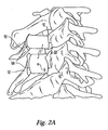
- FIGS. 2A and 2B are side and top views of the implant of FIG. 1 installed in a patient between the cut lamina ends in a unilateral laminoplasty procedure.
- FIG. 2A two different sized implants 1 are installed on the cut lamina segments 10 of adjacent vertebrae, to illustrate application of the implant design to bones of different size.
- FIG. 2B shows the interaction between the implant and the cut vertebra segments 10.
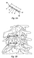
- FIG. 3A is a perspective view of a plate 12 which may be installed to secure the implant 1 of FIGS. 1 & 2, to ensure the implant 1 is not expelled from the cut lamina ends 10.
- Plate 12 has a length 13, a thickness 14 and a body portion 15 with first and second ends 16A, 16B comprising bone engaging portions 17 and implant engaging portions 18. As shown in FIG.
- the bone engaging portions 17 and implant engaging portions 18 may consist of the holes adapted for receiving bone screws 19 or hooks 20 (not shown) capable of grasping bone screws installed in the lamina and/or implant.
- Each side of plate 12 may have one or more bone engaging portions 19 and one or more implant engaging portions 18.
- the plate 12 may be flexible to allow the surgeon to form it to the individual contour of the patient's spine, thereby achieving a tight fit between components.
- the plates may be fabricated from a biocompatable metal or other material known in the art that would be suitable for long term retention of an implant 1.
- each plate comprising at least one bone engaging portion 17 and one implant engaging portion 18.
- FIG. 3B is a side view of the implants 1 installed in FIG. 2A, further showing the installation of optional plates 12 of FIG. 3A.
- Bone screws 19 are installed to secure the plates 12 to both the respective opposing lamina segment 10, and the implant.
- bone screws are also installed in the screw holes 18 of the implant engaging portion, to secure the plates to the implants 1.
- the plates are flexible and are bent to assume the varying contour of the lamina segments and the implant. More than one optional plate may be used to secure the implant to the lamina.
- FIGS. 4A and 4B show perspective and side views of an allograft implant 30 which incorporates the design features of the implants of FIG. 1, but which further includes a pair of bone flaps 31A, 31B disposed at first and second ends 32A, 32B of the implant 30. These bone flaps are used to secure the implant 30 to the respective cut ends of lamina in a unilateral laminoplasty procedure. At least a portion of each flap comprises demineralized bone. Demineralization of the flaps, but not the implant, provides the implant with flexible attachment points which may be contoured to conform to the shape of the adjacent lamina.
- Bone flaps 31A, 31B comprise thin, flat, rectangular segments of allograft having an outer surface 34 and a bone engaging surface 35.
- the outer surfaces 34 of the flaps preferably are the same width as, are contiguous with, and extend axially like wings from the outer surface 36 of the implant 30.
- bone flaps 31A, 31B are machined from the same segment of donor bone as implant 30. At least a portion of flaps 31A, 31B may be demineralized using any commercially acceptable process (e.g. hydrochloric acid bath, etc.) that will render the resulting flaps flexible.
- Flaps 31A, B are provided with holes 36A, 36B suitable for receiving bone screws 37A, 37B which are used to secure the bone flaps 31A, 31B and implant 30 to the adjacent cut lamina ends.
- each bone flap may not be demineralized, but instead each bone flap may comprise a notch 131A, 131B in the respective region where the bone flaps 31A, 3 1 B connect to the implant 30.
- Notches 131A, 131B may be any type of notch or reduction in the thickness of the bone flap appropriate to provide flexibility for placing the flaps on the adjacent laminae surfaces, while retaining the requisite strength to ensure the bone flaps will not separate from the implant during installation.
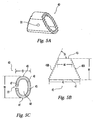
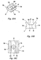
- FIGS. 5A, 5B and 5C show an embodiment of an implant for use in a bilateral or "french door” laminoplasty procedure, in which the spinous process of a targeted vertebra is bisected along the sagittal plane and the segments separated to enlarge the spinal canal.
- the implant 40 has a wall 45 having an inside surface 47 and an outside surface 48, and first and second ends 46A, 46B.
- the outside surface 48 has an outer side region 41 having an outer side length 42 and an inner side region 43 having an inner side length 44.
- Inside surface 47 communicates with first and second ends 46A & 46B to define a hollow central region 49 of the implant.
- the implant 40 has a generally trapezoidal shape when viewed from the side (FIG.
- Inner side region forms angle "TA" with respect to the first and second ends 46A, 46B.
- This trapezoidal configuration allows the implant first and second ends 46A, 46B to conform to the cut, angled surfaces of the spinous process segments to which the implant will eventually fuse.
- Inner side length 44 preferably is from between about 6.0 mm to about 10 mm, and angle "TA" preferably is from between about 50 to about 70 degrees.
- outside surface 48 is not critical and, therefore, any implant external configuration can be used preferably so long as first and second ends 46A, 46B provide sufficient contact area with the cut spinous process segments, does not project out from between the bone segments so far as to interfere with other anatomy, and does not intrude on the spinal cord space
- the outside surface 41 of the implant 40 should preferably not extend beyond the outside surface of the cut spinous process segments.
- the outside surface 41 of the implant 40 is configured such that the outside surface 41, when viewed from the end, displays the form of a substantially geometric shape (e.g. ellipse, oval, circle, etc.) (FIG. 5C).
- the inside surface 43 of the implant 40 may be machined so that the hollow central region 49 approximates the configuration and geometry of the implant outside surface 41 ( i . e . an ellipse or oval).
- the hollow central area is designed to be packed with osteogenic material such as bone chips, etc. to facilitate fusion of the implant with the patient's cut spinous process segments.
- this center area may be made as large as possible to facilitate the fusion process.
- the thickness of wall 45 preferably should be from between about 1.00 to about 1.50 mm; more preferably about 1.25 mm. Preferably the thickness of wall 45 should not be less than about 1.0 mm to ensure the implant retains sufficient strength to withstand the stresses imparted on the spine associated with daily living.
- the implant 40 may be fabricated from a biocompatable metal (e.g. stainless steel, or titanium, etc.) or polymer, or from allograft material preferably taken from a long bone (e.g. femur, tibia, fibula, humerus). Where the implant is fabricated from metal or polymer, it may be provided in a solid form. Preferably, however, the implant should incorporate a hollow region, and the inside surface 44, should be formed to maximize the space available for packing with osteogenic material while maintaining adequate wall thickness. Where the implant is an allograft, the inside surface 44 and hollow center 49 may be defined by the intermedullary canal of the donor bone.
- a biocompatable metal e.g. stainless steel, or titanium, etc.
- allograft material preferably taken from a long bone (e.g. femur, tibia, fibula, humerus).
- the implant may be provided in a solid form.
- the implant should incorporate a hollow region,
- the allograft may be left in this state, and the hollow central region 49 packed with osteogenic material.
- the inside surface 44 of the allograft will be machined and the hollow central region 49 enlarged to maximize the space available for packing with osteogenic material.
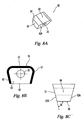
- FIGS. 6A and 6B show first and second ends 46A, 46B of implant 40 each incorporating a channel 50 to accept the corresponding arms of a set of distractor pliers (not shown) which may be used to separate the bisected spinous process segments during the bilateral laminoplasty procedure.
- Each channel 50 has two sidewalls 51 each having a depth "CD", a bottom surface 52 having a width "CW" and a centerline 54 which is formed by a line extending along the implant 40 from inner side surface 43 to outer side surface 41.
- each channel 50 may incorporate a radiused transition 55 between the sidewalls 51 and the bottom surface 52.
- the channel runs from the inner side surface 43 to the outer side surface 41 of each end 46A, 46B of the implant.
- the channel bottom surface width "CW" is about 4 mm
- the sidewall depth "CD” is about 1 mm.
- FIG. 7 shows a further embodiment of bilateral laminoplasty implant 40, in which first and second ends 46A, 46B comprise surface projections to improve pre-fusion retention of the implant 40 between respective cut spinous process segments.
- first and second ends 46A, 46B comprise surface projections to improve pre-fusion retention of the implant 40 between respective cut spinous process segments.
- a plurality of saw-tooth serrations 56 having a height 58 and a tooth angle 59 are provided.
- the serrations are oriented to run vertically when the implant 40 is installed in the patient.
- Height 58 and tooth angle 59 are defined with respect to the respective planes formed by implant first and second ends 46A, 46B.
- Height 58 is measured from the trough 60 of each serration, while tooth angle is measured from the plane formed by the implant first and second ends 46A, 46B.
- height 58 is about 0.5 mm
- tooth angle 59 is about 45 degrees
- the distance between troughs 60 is about 1.2 mm. While these dimensions and profile are preferred, other suitable surface profiles (e.g. pyramidal teeth, etc.) may be used to ensure implant retention.
- first and second ends 46A, 46B may comprise regions of partially, substantially, or fully demineralized cortical bone to further facilitate fusion of the implant to the lamina.
- the partially, substantially, or fully demineralized bone portion may comprise the entire surface of each first and second ends 46A, 46B of the implant 40.
- the depth of the demineralized portion of will be up to about 2 mm.
- the implant 40 may also incorporate a plurality of sutures holes 61 (see FIG. 5C) formed through the implant wall 45 to allow the surgeon to secure the implant to the cut spinous process segments.
- These suture holes 61 may vary in number, size and position, with the only limitation being that their size, position and number preferably should not compromise the strength and integrity of the implant.
- FIGS. 8A, 8B and 8C show a further embodiment of an implant for use in a bilateral laminoplasty procedure.
- Implant 62 has a first and second ends 63A, 63B, an inner side region 68, an outer side region 65, and sides 66 and 67.
- the implant 62 like the implant of FIG. 5, has a generally trapezoidal shape when viewed from the side (FIG. 8C). Again, this trapezoidal configuration allows the implant first and second ends 63A, 63B to conform to the cut, angled surfaces of the spinous process segments to which the implant will eventually fuse.
- inner side 68 forms angle "IA" with respect to the first and second ends 63A, 63B.
- the implant 62 is an allograft, comprising "tri-cortical" bone taken from the crest of the ilium region of the pelvis. Harvesting bone from this segment of the pelvis provides an implant which naturally comprises a thin region 64 of cortical bone on outer side 65, and sides 66 & 67.
- the inner side 68 of the implant, as well as the implant body portion 69 comprise cancellous bone. This combination of bone types allows the surgeon to exploit both the good strength characteristics of cortical bone, and the good osteogenic characteristics of cancellous bone in a single implant.
- the implant 62 comprises a cavity 70 which communicates with implant first and second ends 63A & 63B, and which may be used for packing osteogenic material to promote fusion between the implant and the cut spinous process segments.
- the implant first and second ends 63A, 63B comprise surface projections to improve pre-fusion retention of the implant 62 between respective cut spinous process segments.
- Saw-tooth serrations similar to those illustrated and described with regard to the implant of FIG. 5, may be provided.
- other suitable surface profiles e.g. pyramidal teeth, etc. may also be provided to ensure implant retention.
- first and second ends 63A, 63B may comprise regions of partially, substantially, or fully demineralized cortical bone to further facilitate fusion of the implant to the lamina.
- the demineralized bone portion may comprise the entire surface of each first and second ends 63A, 63B of the implant 62.
- the depth of the demineralized portion of will be up to about 2 mm.
- the implant 62 may incorporate a plurality of sutures holes (not shown) similar to those shown in FIG. 5C, to allow the surgeon to secure the implant to the cut spinous process segments.
- These suture holes may vary in number, size and position, with the only limitation being that their number, size and position should not compromise the strength and integrity of the implant.
- FIGS. 9A and 9B are front and top views of either trapezoidal implants 40, 62 of FIGS. 5, 8 installed in a patient.
- First and second ends 46A, 46B, 63A, 63B of implant 40, 62 contact cut spinous process segments 72 and 71 respectively.
- Hinge cuts 73 and 74 in lamina 75, 76 enable the spinous process segments to be "swung out" by the surgeon to facilitate insertion of the implant 40, 62 therebetween.
- FIGS. 10A, 10B and 10C show a further embodiment of an implant adapted for use in a unilateral laminoplasty procedure.
- Implant 77 comprises first and second plate portions 78A, 78B for connecting to the opposing segments of cut lamina produced during a unilateral laminoplasty procedure.
- First and second plate portions 78A, 78B are connected by an intermediate portion 80.
- the plate portions further comprise respective first and second bone engaging portions 79A, 79B which are configured to engage the opposing cut lamina segments.
- first and second bone engaging portions 79A, 79B comprise arcuate surfaces for engaging and cradling the respective cut lamina ends.
- Arcuate surfaces are particularly suited for this purpose because their concave shape can engage and retain lamina segments residing along different axes, a phenomenon which occurs during the unilateral laminoplasty procedure when a single lamina is cut and the resulting segments are swung out to enlarge the area available for the spinal cord.
- the swinging out process results in an angle being formed between the segments, and it is this misalignment which the arcuate surfaces of the bone engaging portions 79A & 79B accommodate.
- the thickness of the intermediate portion 80 may be smaller than the height of the first and second plate portions 78A, 78B.
- Implant 77 may be fabricated from any biocompatable metal (e.g. titanium, stainless steel, etc.) or polymer, or the implant may be formed of allograft material. If allograft is used, the implant 77 preferably should be fabricated from cortical bone.
- first and second bone engaging portions 79A, 79B may comprise regions of partially, substantially, or fully demineralized cortical bone to further facilitate fusion of the implant to the lamina segments.
- the demineralized bone portion may comprise the entire surface of each first and second bone engaging portions 79A, 79B.
- the depth of the demineralized portion will be up to about 2 mm.
- the implant 77 may incorporate suture hole 80 to allow the surgeon to secure the implant to the cut spinous process segments. Additional suture holes (not shown) may be provided, and may vary in number, size and position, with the only limitation being that their size, position and number preferably should not compromise the strength and integrity of the implant 77.
- FIGS. 11A, 11B and 11C show a further embodiment of an implant adapted for use in a unilateral laminoplasty procedure.
- Implant 84 comprises a plate portion 85 having bone engaging portions 86A, 86B, a graft engaging portion 87, and an allograft 91.
- Bone engaging portions 86A, 86B further comprise a plurality of suture holes 88 configured to allow the surgeon to secure the cut lamina segments to bone engaging portions 86A, 86B
- Graft engaging portion 87 comprises a graft seating surface 89 and a graft retaining portion 90 configured to retain a correspondingly shaped allograft 91 for engaging the opposing cut lamina segment.
- graft retaining portion 90 comprises two raised tabs 92A, 92B, each residing along at least a portion of opposing ends of graft seating surface 89.
- raised tabs 92A, 92B are angled slightly toward the center of graft seating surface 89 so as to facilitate retention of allograft 91.
- the angle "A" between raised tabs 92A, 92B and graft seating surface 89 will be from about 70 to about 80 degrees; more preferably this angle will be about 75 degrees.
- Plate portion 85 further comprises a bottom surface 855. When installed, graft 91 comprises the inner side surface of the implant (i.e.
- bottom surface 855 comprises the outer side surface of the implant (i.e. the surface which faces away from the spinal canal).
- bottom surface 855 comprises a convex shape which assumes the rounded contour of the lamina segments.
- this convex surface has a radius of about 18 mm.
- Plate portion 85 may be fabricated from any biocompatable metal (e.g. titanium, stainless steel, etc.) or polymer, or it may be made of allograft material. If allograft is used, the plate portion 85 may be fabricated from cortical bone. Graft 91 preferably may be comprised of a cancellous type bone material to facilitate fusion of the implant to the patient's lamina.
- FIGS. 12A and 12B show implant embodiments comprising plates configured to attach directly to the opposing cut segments of lamina produced during a unilateral laminoplasty. These plates are further configured to capture segments of allograft and to engage these segments with the opposing cut segments of lamina to facilitate fusion between the implant and the patient's bone.
- Plate 93 comprises a body portion 94 having a longitudinal axis and first and second ends 95A, 95B, and a graft retaining portion 96, midway between the ends 95A, 95B, preferably approximately midway between ends 95A, 95B.
- First and second ends 95A, 95B each comprise a bone engaging portion 97.
- the bone engaging portion at each first and second end comprises at least one hole suitable for receiving a bone screw 98 (not shown).
- the bone screws are then used to secure the plate 93 to each opposing segment of lamina.
- the bone engaging portions may be hooks capable of grasping bone screws that are installed in the lamina segments.
- the graft retaining portion 96 comprises a plurality of deformable fingers 99 which are initially arrayed flat along an axis perpendicular to the longitudinal axis of the plate 93. These fingers 99 are capable of being deformed to cradle an allograft 100, preferably cylindrical in shape. Allograft 100 preferably has a length sufficient to engage the cut ends of lamina upon installation, and a diameter of size sufficient to be captured by the deformed fingers 99 of the plate 93.
- plate 93 has a graft retaining portion 96 which comprises a hollow region 101, preferably rectangular in shape.
- a correspondingly configured allograft of cancellous bone is provided having a body 102 capable of being received within the hollow region 101, and further having shoulders 103 which extends beyond the hollow region to contact seating surface 104.
- shoulders 103 of allograft 100 are secured to plate 93 using a bone screw 98 placed through bone engaging portion 97.
- the plate 93 may be flexible to allow the surgeon to form the body 94 to the individual contour of the patient's spine, thereby achieving a tight fit between components.
- the plate 93 may be fabricated from a biocompatable metal or other material known in the art that would be suitable for long term retention of an implant and graft.
- the current invention also provides a method of using an allograft implant according to any of the embodiments shown in FIGS. 1A, 5A, 8A, 10A or 11A which further has partially, substantially, or fully demineralized end segments to promote fusion between opposing segments of lamina or spinous process produced during a unilateral or bilateral laminoplasty procedure.
- This method comprises the steps of cutting a targeted lamina or spinous process as required for either a unilateral or bilateral laminoplasty procedure, separating the resulting segments of bone a sufficient distance to allow for insertion of an appropriately sized allograft implant, providing an allograft implant having bone engaging surfaces which comprise partially, substantially, or fully demineralized cortical bone to a depth of up to about 2 mm, and contacting the allograft implant bone engaging surfaces with respective cut segments of lamina or spinous process.
- This method may be augmented, in the case of a unilateral laminoplasty, to include the additional step of installing a plate over the allograft implant to further assist retention of the implant between the bone segments. Where such a plate is provided, the additional steps of providing bone screws or other fasteners to attach the plate to the opposing segments of bone and/or to attach the plate to the implant, may further be included.
- a further embodiment of the above method comprises providing an allograft implant according to the above method, which implant further has partially, substantially, or fully demineralized bone flaps capable of receiving bone screws. Providing such an implant allows the surgeon to affirmatively secure the implant to the cut lamina segments, preferably without the need for a separate plate.
- a method of installing a tri-cortical allograft implant as part of a bilateral laminoplasty procedure comprises the steps of bisecting a targeted spinous process, providing hinge cuts on both adjacent lamina sufficient to allow the spinous process segments to be spread apart, separating the spinous process segments to allow for insertion of an appropriately sized allograft implant, providing an allograft implant having first and second angled bone engaging surfaces which approximate the angle between the bisected and spread spinous process segment cut surfaces, the allograft implant comprising cancellous bone material having a thin outer layer of cortical bone surrounding the cancellous bone, and which cortical bone layer is in communication with the first and second engaging surfaces so as to support the compressive stresses imparted by the cut spinous process segments.
- a method of using only a screwed plate to maintain the distance between bone ends produced during a unilateral or bilateral laminoplasty procedure comprises the steps of cutting a targeted lamina or spinous process as required for the respective laminoplasty procedure, separating the cut bone segments to increase the space available for the spinal canal and associated nerves, providing an appropriately sized plate having first and second ends, wherein each end is configured to allow engagement with the surface of the lamina opposite the surface of the spinal canal and adjacent the cut bone end, and securing first and second ends of the plate to the adjacent bone segments.
- each first and second end of the plate will have at least one recess suitable for receiving a bone screw, wherein the plate is secured to the adjacent cut bone ends using bone screws.
- two plates may be provided to attach to the adjacent cut bone ends.
Applications Claiming Priority (2)
| Application Number | Priority Date | Filing Date | Title |
|---|---|---|---|
| US09/942,335 US6635087B2 (en) | 2001-08-29 | 2001-08-29 | Laminoplasty implants and methods of use |
| EP02753537A EP1420708B1 (fr) | 2001-08-29 | 2002-08-26 | Implants de laminoplastie a greffe capturee |
Related Parent Applications (1)
| Application Number | Title | Priority Date | Filing Date |
|---|---|---|---|
| EP02753537A Division EP1420708B1 (fr) | 2001-08-29 | 2002-08-26 | Implants de laminoplastie a greffe capturee |
Publications (1)
| Publication Number | Publication Date |
|---|---|
| EP1698294A1 true EP1698294A1 (fr) | 2006-09-06 |
Family
ID=25477944
Family Applications (2)
| Application Number | Title | Priority Date | Filing Date |
|---|---|---|---|
| EP02753537A Expired - Lifetime EP1420708B1 (fr) | 2001-08-29 | 2002-08-26 | Implants de laminoplastie a greffe capturee |
| EP06011279A Withdrawn EP1698294A1 (fr) | 2001-08-29 | 2002-08-26 | Implants pour le rachis qui tiennent des allogreffes |
Family Applications Before (1)
| Application Number | Title | Priority Date | Filing Date |
|---|---|---|---|
| EP02753537A Expired - Lifetime EP1420708B1 (fr) | 2001-08-29 | 2002-08-26 | Implants de laminoplastie a greffe capturee |
Country Status (8)
| Country | Link |
|---|---|
| US (1) | US6635087B2 (fr) |
| EP (2) | EP1420708B1 (fr) |
| AT (1) | ATE330544T1 (fr) |
| CA (1) | CA2537040C (fr) |
| DE (1) | DE60212648T2 (fr) |
| ES (1) | ES2266543T3 (fr) |
| HK (1) | HK1064018A1 (fr) |
| WO (1) | WO2003020141A1 (fr) |
Families Citing this family (95)
| Publication number | Priority date | Publication date | Assignee | Title |
|---|---|---|---|---|
| DE69924864T2 (de) * | 1998-10-30 | 2006-02-23 | Michelson, Gary Karlin, Los Angeles | Selbsträumendes, rotierbares, einsteckbares spondylose implantat |
| US6245108B1 (en) * | 1999-02-25 | 2001-06-12 | Spineco | Spinal fusion implant |
| FR2897259B1 (fr) | 2006-02-15 | 2008-05-09 | Ldr Medical Soc Par Actions Si | Cage intersomatique transforaminale a greffon de fusion intervetebrale et instrument d'implantation de la cage |
| FR2808995B1 (fr) | 2000-05-18 | 2003-02-21 | Aesculap Sa | Cage intersomatique a greffons unifies |
| US6358254B1 (en) | 2000-09-11 | 2002-03-19 | D. Greg Anderson | Method and implant for expanding a spinal canal |
| US7166107B2 (en) * | 2000-09-11 | 2007-01-23 | D. Greg Anderson | Percutaneous technique and implant for expanding the spinal canal |
| US20020120335A1 (en) * | 2001-02-28 | 2002-08-29 | Angelucci Christopher M. | Laminoplasty implants and methods of use |
| FR2827156B1 (fr) | 2001-07-13 | 2003-11-14 | Ldr Medical | Dispositif de cage vertebrale avec fixation modulaire |
| US20030130738A1 (en) * | 2001-11-08 | 2003-07-10 | Arthrocare Corporation | System and method for repairing a damaged intervertebral disc |
| AU2002366381A1 (en) * | 2001-12-18 | 2003-06-30 | Ebi, L.P. | Spinal implants |
| US9480503B2 (en) * | 2002-01-03 | 2016-11-01 | Rohit Khanna | Universal laminoplasty implant |
| US20030125738A1 (en) * | 2002-01-03 | 2003-07-03 | Khanna Rohit Kumar | Laminoplasty with laminar stabilization method and system |
| DE50210270D1 (de) * | 2002-03-12 | 2007-07-19 | Cervitech Inc | Zwischenwirbelprothese, insbesondere für die Halswirbelsäule |
| EP1344507A1 (fr) * | 2002-03-12 | 2003-09-17 | Waldemar Link (GmbH & Co.) | Prothèse intervertébrale pour la colonne cervicale |
| US20100168751A1 (en) * | 2002-03-19 | 2010-07-01 | Anderson D Greg | Method, Implant & Instruments for Percutaneous Expansion of the Spinal Canal |
| US9044279B2 (en) * | 2002-03-19 | 2015-06-02 | Innovative Surgical Designs, Inc. | Device and method for expanding the spinal canal with spinal column stabilization and spinal deformity correction |
| US8105366B2 (en) | 2002-05-30 | 2012-01-31 | Warsaw Orthopedic, Inc. | Laminoplasty plate with flanges |
| WO2004008943A2 (fr) * | 2002-07-19 | 2004-01-29 | Osteotech, Inc. | Processus de selection d'os en vue d'une greffe |
| DE60331955D1 (de) * | 2002-09-24 | 2010-05-12 | Bogomir Gorensek | Stabilisierungsvorrichtung für bandscheiben und verfahren dafür |
| US6712852B1 (en) | 2002-09-30 | 2004-03-30 | Depuy Spine, Inc. | Laminoplasty cage |
| US7794456B2 (en) | 2003-05-13 | 2010-09-14 | Arthrocare Corporation | Systems and methods for electrosurgical intervertebral disc replacement |
| US7811329B2 (en) | 2003-07-31 | 2010-10-12 | Globus Medical | Transforaminal prosthetic spinal disc replacement and methods thereof |
| US7713304B2 (en) | 2003-07-31 | 2010-05-11 | Globus Medical, Inc. | Transforaminal prosthetic spinal disc replacement |
| US7621956B2 (en) * | 2003-07-31 | 2009-11-24 | Globus Medical, Inc. | Prosthetic spinal disc replacement |
| WO2005039390A2 (fr) | 2003-10-20 | 2005-05-06 | Arthrocare Corporation | Procede et appareil d'electrochirurgie destines a retirer un tissu de l'interieur d'un corps osseux |
| WO2005041752A2 (fr) * | 2003-10-20 | 2005-05-12 | Blackstone Medical, Inc. | Plaque vissee et procede d'utilisation de la plaque |
| US20050107877A1 (en) * | 2003-10-30 | 2005-05-19 | Nu Vasive, Inc. | System and methods for restoring the structural integrity of bone |
| PL2113227T3 (pl) | 2004-02-04 | 2015-12-31 | Ldr Medical | Proteza krążka międzykręgowego |
| WO2005096969A1 (fr) * | 2004-04-07 | 2005-10-20 | C G Surgical Limited | Dispositifs de stabilisation de la lame vertebrale |
| US7264620B2 (en) * | 2004-06-04 | 2007-09-04 | Depuy Spine, Inc. | Variable laminoplasty implant |
| US9504583B2 (en) * | 2004-06-10 | 2016-11-29 | Spinal Elements, Inc. | Implant and method for facet immobilization |
| EP1814474B1 (fr) | 2004-11-24 | 2011-09-14 | Samy Abdou | Dispositifs de placement d'un dispositif orthopedique intervertebral |
| US20070049941A1 (en) * | 2005-08-25 | 2007-03-01 | Lanx, Llc | Plate with stabilization |
| FR2891135B1 (fr) | 2005-09-23 | 2008-09-12 | Ldr Medical Sarl | Prothese de disque intervertebral |
| US7744630B2 (en) * | 2005-11-15 | 2010-06-29 | Zimmer Spine, Inc. | Facet repair and stabilization |
| US20070198016A1 (en) * | 2006-02-21 | 2007-08-23 | Osteomed, L.P. | Compression stabilizing spacers |
| US7879034B2 (en) | 2006-03-02 | 2011-02-01 | Arthrocare Corporation | Internally located return electrode electrosurgical apparatus, system and method |
| US8246663B2 (en) * | 2006-04-10 | 2012-08-21 | Scott Lovald | Osteosynthesis plate, method of customizing same, and method for installing same |
| US7806911B2 (en) * | 2006-04-14 | 2010-10-05 | Warsaw Orthopedic, Inc. | Fixation plate and method of use |
| US8926664B1 (en) | 2006-11-07 | 2015-01-06 | Globus Medical, Inc. | Laminoplasty fixaction devices |
| WO2008112981A1 (fr) * | 2007-03-15 | 2008-09-18 | Blue Fury Consulting, L.L.C. | Implant de laminoplastie |
| US8257395B2 (en) * | 2007-09-21 | 2012-09-04 | Jmea Corporation | Spinal fixation with selectively applied bone growth promoting agent |
| US20090048675A1 (en) * | 2007-04-25 | 2009-02-19 | Bhatnagar Mohit K | Spinal Fusion Implants with Selectively Applied Bone Growth Promoting Agent |
| FR2916956B1 (fr) | 2007-06-08 | 2012-12-14 | Ldr Medical | Cage intersomatique,prothese intervertebrale,dispositif d'ancrage et instrumentation d'implantation |
| US20090177203A1 (en) | 2008-01-04 | 2009-07-09 | Inbone Technologies, Inc. | Devices, systems and methods for re-alignment of bone |
| BRPI0914950A2 (pt) * | 2008-06-19 | 2015-10-20 | Synthes Gmbh | implantes, sistemas e técnicas de aumento da vantagem mecânica de parafusos ósseos |
| US20100057127A1 (en) * | 2008-08-26 | 2010-03-04 | Mcguire Brian | Expandable Laminoplasty Fixation System |
| US8133280B2 (en) | 2008-12-19 | 2012-03-13 | Depuy Spine, Inc. | Methods and devices for expanding a spinal canal |
| US8435265B2 (en) * | 2009-03-18 | 2013-05-07 | Depuy Spine, Inc. | Laminoplasty methods using hinge device |
| WO2011028306A1 (fr) | 2009-09-06 | 2011-03-10 | Cowan Jr John A | Dispositif de spondylodèse à verrouillage |
| CN102596109B (zh) | 2009-09-17 | 2015-10-21 | Ldr控股公司 | 具有可伸展骨固定部件的椎间植入件 |
| US8425520B2 (en) | 2009-10-30 | 2013-04-23 | Depuy Spine, Inc. | Bone plate holder |
| US20110106087A1 (en) * | 2009-10-30 | 2011-05-05 | Gamache Thomas J | Bone Plate Holder |
| US8470003B2 (en) | 2009-10-30 | 2013-06-25 | DePuy Synthes Products, LLC | Laminoplasty plates and methods of expanding the spinal canal |
| US8425515B2 (en) * | 2009-10-30 | 2013-04-23 | Depuy Spine, Inc. | Bone graft loading instruments and methods of connecting a bone graft to a bone plate |
| US8764806B2 (en) | 2009-12-07 | 2014-07-01 | Samy Abdou | Devices and methods for minimally invasive spinal stabilization and instrumentation |
| US8277509B2 (en) | 2009-12-07 | 2012-10-02 | Globus Medical, Inc. | Transforaminal prosthetic spinal disc apparatus |
| WO2011080535A1 (fr) | 2009-12-31 | 2011-07-07 | Lrd Medical | Dispositif d'ancrage, implant intervertébral et instrument d'implantation |
| US20110184468A1 (en) * | 2010-01-28 | 2011-07-28 | Warsaw Orthopedic, Inc., An Indiana Corporation | Spinous process fusion plate with osteointegration insert |
| US8945227B2 (en) * | 2010-02-01 | 2015-02-03 | X-Spine Systems, Inc. | Spinal implant co-insertion system and method |
| US8444699B2 (en) * | 2010-02-18 | 2013-05-21 | Biomet Manufacturing Corp. | Method and apparatus for augmenting bone defects |
| US8979838B2 (en) | 2010-05-24 | 2015-03-17 | Arthrocare Corporation | Symmetric switching electrode method and related system |
| US8343229B2 (en) | 2010-07-16 | 2013-01-01 | Ebi, Llc | Textured bone block implants |
| US8480747B2 (en) | 2010-08-11 | 2013-07-09 | Warsaw Orthopedic, Inc. | Interbody spinal implants with extravertebral support plates |
| FR2966718B1 (fr) * | 2010-10-28 | 2013-07-26 | Medicrea International | Implant de laminoplastie, notamment cervicale |
| WO2012118843A1 (fr) * | 2011-02-28 | 2012-09-07 | Tissue Regeneration Systems, Inc. | Échafaudages modulaires pour tissus |
| US8454694B2 (en) | 2011-03-03 | 2013-06-04 | Warsaw Orthopedic, Inc. | Interbody device and plate for spinal stabilization and instruments for positioning same |
| US9351781B2 (en) | 2011-04-12 | 2016-05-31 | Aesculap Ag | Surgical procedure for expanding a vertebral canal |
| DE102011001996A1 (de) * | 2011-04-12 | 2012-10-18 | Aesculap Ag | Chirurgisches Implantat zum Erweitern eines Wirbelkanals |
| US10226284B2 (en) * | 2011-09-01 | 2019-03-12 | Globus Medical, Inc. | Laminoplasty plates, systems, and devices, and methods relating to the same |
| US8845728B1 (en) | 2011-09-23 | 2014-09-30 | Samy Abdou | Spinal fixation devices and methods of use |
| US9017410B2 (en) | 2011-10-26 | 2015-04-28 | Globus Medical, Inc. | Artificial discs |
| US8562681B2 (en) | 2012-01-31 | 2013-10-22 | Styker Spine | Laminoplasty implant, method and instrumentation |
| US20130226240A1 (en) | 2012-02-22 | 2013-08-29 | Samy Abdou | Spinous process fixation devices and methods of use |
| FR2987256B1 (fr) | 2012-02-24 | 2014-08-08 | Ldr Medical | Dispositif d'ancrage pour implant intervertebral, implant intervertebral et instrumentation d'implantation |
| US9913666B2 (en) | 2012-04-04 | 2018-03-13 | Carl P. Giordano | Plates configured to rigidly fix fragments of a pars interarticularis to one another |
| US9615860B2 (en) | 2012-04-04 | 2017-04-11 | Carl Pasquale Giordano | Plates configured to rigidly fix fragments of a pars interarticularis to one another |
| US10709482B2 (en) | 2012-05-30 | 2020-07-14 | Globus Medical, Inc. | Laminoplasty system |
| US9138325B2 (en) * | 2012-07-11 | 2015-09-22 | Globus Medical, Inc. | Lamina implant and method |
| US9198767B2 (en) | 2012-08-28 | 2015-12-01 | Samy Abdou | Devices and methods for spinal stabilization and instrumentation |
| US9320617B2 (en) | 2012-10-22 | 2016-04-26 | Cogent Spine, LLC | Devices and methods for spinal stabilization and instrumentation |
| US10327910B2 (en) | 2013-03-14 | 2019-06-25 | X-Spine Systems, Inc. | Spinal implant and assembly |
| US9198770B2 (en) | 2013-07-31 | 2015-12-01 | Globus Medical, Inc. | Artificial disc devices and related methods of use |
| US9566169B2 (en) | 2014-03-13 | 2017-02-14 | DePuy Synthes Products, Inc. | ACIS allograft designs |
| US9717541B2 (en) | 2015-04-13 | 2017-08-01 | DePuy Synthes Products, Inc. | Lamina implants and methods for spinal decompression |
| US10857003B1 (en) | 2015-10-14 | 2020-12-08 | Samy Abdou | Devices and methods for vertebral stabilization |
| JP6537432B2 (ja) * | 2015-10-19 | 2019-07-03 | HOYA Technosurgical株式会社 | スペーサ |
| USD849946S1 (en) | 2015-12-30 | 2019-05-28 | Nuvasive, Inc. | Interspinous process spacer |
| US10058432B2 (en) | 2016-03-03 | 2018-08-28 | Globus Medical, Inc. | Lamina plate assembly |
| US10667916B2 (en) | 2016-03-03 | 2020-06-02 | Globus Medical, Inc. | Lamina plate assembly |
| US10376292B2 (en) | 2016-03-03 | 2019-08-13 | Globus Medical, Inc | Lamina plate assembly |
| US10973648B1 (en) | 2016-10-25 | 2021-04-13 | Samy Abdou | Devices and methods for vertebral bone realignment |
| US10744000B1 (en) | 2016-10-25 | 2020-08-18 | Samy Abdou | Devices and methods for vertebral bone realignment |
| US11826082B1 (en) | 2018-06-29 | 2023-11-28 | Choice Spine, Llc | Laminoplasty hinged plate with integrated spacer |
| US11179248B2 (en) | 2018-10-02 | 2021-11-23 | Samy Abdou | Devices and methods for spinal implantation |
Citations (8)
| Publication number | Priority date | Publication date | Assignee | Title |
|---|---|---|---|---|
| EP0599766A1 (fr) * | 1992-09-07 | 1994-06-01 | José Vicente Barbera Alacreu | Système de fusion des vertèbres cervicales |
| FR2727005A1 (fr) * | 1994-11-18 | 1996-05-24 | Euros Sa | Dispositif de stabilisation anterieure du rachis cervical |
| DE19630256A1 (de) * | 1996-07-26 | 1998-01-29 | Heinrich Ulrich | Implantat zum Fusionieren von zwei benachbarten Wirbeln der Wirbelsäule |
| JPH10179622A (ja) * | 1996-12-20 | 1998-07-07 | Mizuho Ika Kogyo Kk | 脊椎インプラント |
| US6080157A (en) * | 1995-09-12 | 2000-06-27 | Cg Surgical Limited | Device to stabilize the lamina |
| US6235059B1 (en) * | 1996-04-03 | 2001-05-22 | Scient'x (Societe A Responsabilite Limitee) | Intersomatic setting and fusion system |
| EP1103236A2 (fr) * | 1999-11-24 | 2001-05-30 | DePuy Acromed, Inc. | Cage de fusion intervertébrale lombaire antérieure avec plaque de fixation |
| WO2003020143A1 (fr) * | 2001-02-28 | 2003-03-13 | Synthes (U.S.A.) | Implants de laminoplastie bilaterale |
Family Cites Families (111)
| Publication number | Priority date | Publication date | Assignee | Title |
|---|---|---|---|---|
| DE8105177U1 (de) | 1981-02-25 | 1984-01-12 | Schuett Und Grundei Gmbh Medizintechnische Fabrikation, 2400 Luebeck | Implantat als Ersatz für spongiöse Knochen |
| US4877020A (en) | 1984-11-30 | 1989-10-31 | Vich Jose M O | Apparatus for bone graft |
| US4627853A (en) | 1985-05-29 | 1986-12-09 | American Hospital Supply Corporation | Method of producing prostheses for replacement of articular cartilage and prostheses so produced |
| US4678470A (en) | 1985-05-29 | 1987-07-07 | American Hospital Supply Corporation | Bone-grafting material |
| US5053049A (en) | 1985-05-29 | 1991-10-01 | Baxter International | Flexible prostheses of predetermined shapes and process for making same |
| US4743256A (en) | 1985-10-04 | 1988-05-10 | Brantigan John W | Surgical prosthetic implant facilitating vertebral interbody fusion and method |
| KR960005871B1 (ko) | 1986-05-15 | 1996-05-03 | 스미또모 시멘트 가부시끼가이샤 | 인공생체복합재료 |
| DE3637314A1 (de) | 1986-11-03 | 1988-05-11 | Lutz Biedermann | Platzhalter-implantat |
| US4834757A (en) | 1987-01-22 | 1989-05-30 | Brantigan John W | Prosthetic implant |
| US5147404A (en) | 1987-12-07 | 1992-09-15 | Downey Ernest L | Vertebra prosthesis |
| US4950296A (en) | 1988-04-07 | 1990-08-21 | Mcintyre Jonathan L | Bone grafting units |
| US5609635A (en) | 1988-06-28 | 1997-03-11 | Michelson; Gary K. | Lordotic interbody spinal fusion implants |
| CA1333209C (fr) | 1988-06-28 | 1994-11-29 | Gary Karlin Michelson | Implants artificiels pour la soudure osseuse intervertebrale |
| US4892545A (en) * | 1988-07-14 | 1990-01-09 | Ohio Medical Instrument Company, Inc. | Vertebral lock |
| CN1046845A (zh) | 1989-04-30 | 1990-11-14 | 张懋 | 骨折内固定z形板及其接骨方法 |
| US5062845A (en) | 1989-05-10 | 1991-11-05 | Spine-Tech, Inc. | Method of making an intervertebral reamer |
| US5458638A (en) | 1989-07-06 | 1995-10-17 | Spine-Tech, Inc. | Non-threaded spinal implant |
| US5290558A (en) | 1989-09-21 | 1994-03-01 | Osteotech, Inc. | Flowable demineralized bone powder composition and its use in bone repair |
| US5112354A (en) | 1989-11-16 | 1992-05-12 | Northwestern University | Bone allograft material and method |
| JPH066810Y2 (ja) | 1989-11-29 | 1994-02-23 | 旭光学工業株式会社 | 椎体固定用プレート |
| US5236460A (en) | 1990-02-12 | 1993-08-17 | Midas Rex Pneumatic Tools, Inc. | Vertebral body prosthesis |
| US5192327A (en) | 1991-03-22 | 1993-03-09 | Brantigan John W | Surgical prosthetic implant for vertebrae |
| US5290312A (en) | 1991-09-03 | 1994-03-01 | Alphatec | Artificial vertebral body |
| DE9112176U1 (fr) | 1991-09-30 | 1991-11-14 | Howmedica Gmbh, 2314 Schoenkirchen, De | |
| US5534031A (en) | 1992-01-28 | 1996-07-09 | Asahi Kogaku Kogyo Kabushiki Kaisha | Prosthesis for spanning a space formed upon removal of an intervertebral disk |
| US5766251A (en) | 1992-03-13 | 1998-06-16 | Tomihisa Koshino | Wedge-shaped spacer for correction of deformed extremities |
| US5306309A (en) | 1992-05-04 | 1994-04-26 | Calcitek, Inc. | Spinal disk implant and implantation kit |
| US6066175A (en) * | 1993-02-16 | 2000-05-23 | Henderson; Fraser C. | Fusion stabilization chamber |
| EP0654979B1 (fr) | 1993-06-11 | 1998-03-04 | Hillway Surgical Limited | Implant chirurgical |
| US5360430A (en) | 1993-07-29 | 1994-11-01 | Lin Chih I | Intervertebral locking device |
| FR2708461B1 (fr) | 1993-08-06 | 1995-09-29 | Advanced Technical Fabrication | Implant intersomatique pour colonne vertébrale. |
| DE4328062A1 (de) | 1993-08-20 | 1995-02-23 | Heinrich Ulrich | Implantat zum Ersatz von Wirbelkörpern und/oder zur Stabilisierung und Fixierung der Wirbelsäule |
| DE4328690B4 (de) | 1993-08-26 | 2006-08-17 | SDGI Holdings, Inc., Wilmington | Zwischenwirbelimplantat zur Wirbelkörperverblockung und Implantationsinstrument zum Positionieren des Zwischenwirbelimplantats |
| US5458641A (en) | 1993-09-08 | 1995-10-17 | Ramirez Jimenez; Juan J. | Vertebral body prosthesis |
| US5425772A (en) | 1993-09-20 | 1995-06-20 | Brantigan; John W. | Prosthetic implant for intervertebral spinal fusion |
| CN1156255C (zh) | 1993-10-01 | 2004-07-07 | 美商-艾克罗米德公司 | 脊椎植入物 |
| US5514180A (en) | 1994-01-14 | 1996-05-07 | Heggeness; Michael H. | Prosthetic intervertebral devices |
| DE4414675C1 (de) | 1994-04-27 | 1995-09-28 | Kirsch Axel | Abdeckeinrichtung für Knochendefektstellen und Verfahren zu deren Herstellung |
| CA2191089C (fr) | 1994-05-23 | 2003-05-06 | Douglas W. Kohrs | Implant pour fusion intervertebrale |
| US5674296A (en) | 1994-11-14 | 1997-10-07 | Spinal Dynamics Corporation | Human spinal disc prosthesis |
| FR2727004A1 (fr) | 1994-11-18 | 1996-05-24 | Euros Sa | Dispositif de stabilisation posterieure du rachis lombaire et lombo-sacre |
| FR2727003B1 (fr) | 1994-11-18 | 1997-04-18 | Euros Sa | Dispositif de stabilisation anterieure du rachis lombo-sacre |
| US5766252A (en) | 1995-01-24 | 1998-06-16 | Osteonics Corp. | Interbody spinal prosthetic implant and method |
| US5860973A (en) | 1995-02-27 | 1999-01-19 | Michelson; Gary Karlin | Translateral spinal implant |
| WO1996027348A1 (fr) | 1995-03-08 | 1996-09-12 | Synthes Ag, Chur | Implant intervertebral |
| US5591235A (en) | 1995-03-15 | 1997-01-07 | Kuslich; Stephen D. | Spinal fixation device |
| US5782919A (en) | 1995-03-27 | 1998-07-21 | Sdgi Holdings, Inc. | Interbody fusion device and method for restoration of normal spinal anatomy |
| US6206922B1 (en) | 1995-03-27 | 2001-03-27 | Sdgi Holdings, Inc. | Methods and instruments for interbody fusion |
| US5702449A (en) | 1995-06-07 | 1997-12-30 | Danek Medical, Inc. | Reinforced porous spinal implants |
| US6039762A (en) | 1995-06-07 | 2000-03-21 | Sdgi Holdings, Inc. | Reinforced bone graft substitutes |
| FR2736538B3 (fr) | 1995-07-12 | 1997-12-19 | Gastambide Daniel | Cage intersomatique pour rachis lombaire |
| US5888222A (en) | 1995-10-16 | 1999-03-30 | Sdgi Holding, Inc. | Intervertebral spacers |
| US5989289A (en) | 1995-10-16 | 1999-11-23 | Sdgi Holdings, Inc. | Bone grafts |
| WO1997015248A1 (fr) | 1995-10-20 | 1997-05-01 | Synthes Ag Chur | Implant intervertebral |
| WO1997015246A1 (fr) | 1995-10-20 | 1997-05-01 | Synthes Ag Chur | Implant intervertebral avec cage et corps de rotation |
| WO1997015247A1 (fr) | 1995-10-20 | 1997-05-01 | Synthes Ag, Chur | Implant intervertebral avec corps creux profile et compressible |
| US5814084A (en) | 1996-01-16 | 1998-09-29 | University Of Florida Tissue Bank, Inc. | Diaphysial cortical dowel |
| US5865845A (en) | 1996-03-05 | 1999-02-02 | Thalgott; John S. | Prosthetic intervertebral disc |
| SE510025C2 (sv) | 1996-05-10 | 1999-04-12 | Robert J Medoff | Fasthållningsanordning för graftmaterial |
| DE19622827B4 (de) | 1996-06-07 | 2009-04-23 | Ulrich, Heinrich | Implantat zum Einsetzen zwischen Wirbelkörper als Platzhalter |
| US6111164A (en) | 1996-06-21 | 2000-08-29 | Musculoskeletal Transplant Foundation | Bone graft insert |
| US5895426A (en) | 1996-09-06 | 1999-04-20 | Osteotech, Inc. | Fusion implant device and method of use |
| US6019793A (en) | 1996-10-21 | 2000-02-01 | Synthes | Surgical prosthetic device |
| US5728159A (en) | 1997-01-02 | 1998-03-17 | Musculoskeletal Transplant Foundation | Serrated bone graft |
| US5861041A (en) | 1997-04-07 | 1999-01-19 | Arthit Sitiso | Intervertebral disk prosthesis and method of making the same |
| JP3887058B2 (ja) * | 1997-04-15 | 2007-02-28 | ペンタックス株式会社 | 人工棘突起 |
| US6149651A (en) | 1997-06-02 | 2000-11-21 | Sdgi Holdings, Inc. | Device for supporting weak bony structures |
| US6033438A (en) | 1997-06-03 | 2000-03-07 | Sdgi Holdings, Inc. | Open intervertebral spacer |
| US5972368A (en) | 1997-06-11 | 1999-10-26 | Sdgi Holdings, Inc. | Bone graft composites and spacers |
| US6241771B1 (en) | 1997-08-13 | 2001-06-05 | Cambridge Scientific, Inc. | Resorbable interbody spinal fusion devices |
| US6090998A (en) | 1997-10-27 | 2000-07-18 | University Of Florida | Segmentally demineralized bone implant |
| US20010001129A1 (en) | 1997-12-10 | 2001-05-10 | Mckay William F. | Osteogenic fusion device |
| US6086613A (en) | 1997-12-23 | 2000-07-11 | Depuy Acromed, Inc. | Spacer assembly for use in spinal surgeries |
| US6143033A (en) | 1998-01-30 | 2000-11-07 | Synthes (Usa) | Allogenic intervertebral implant |
| US6258125B1 (en) * | 1998-08-03 | 2001-07-10 | Synthes (U.S.A.) | Intervertebral allograft spacer |
| DE19807236C2 (de) | 1998-02-20 | 2000-06-21 | Biedermann Motech Gmbh | Zwischenwirbelimplantat |
| US6224631B1 (en) | 1998-03-20 | 2001-05-01 | Sulzer Spine-Tech Inc. | Intervertebral implant with reduced contact area and method |
| US6008433A (en) | 1998-04-23 | 1999-12-28 | Stone; Kevin R. | Osteotomy wedge device, kit and methods for realignment of a varus angulated knee |
| US6241769B1 (en) | 1998-05-06 | 2001-06-05 | Cortek, Inc. | Implant for spinal fusion |
| DE29813139U1 (de) | 1998-07-23 | 1998-12-03 | Howmedica Gmbh | Wirbelkörper-Rekonstruktionssystem |
| AT406011B (de) | 1998-07-30 | 2000-01-25 | Stoffella Rudolf Dr | Implantat zur gegenseitigen fixierung zweier knochenfragmente |
| AU5341999A (en) | 1998-08-06 | 2000-02-28 | Sdgi Holdings, Inc. | Composited intervertebral bone spacers |
| US6099531A (en) | 1998-08-20 | 2000-08-08 | Bonutti; Peter M. | Changing relationship between bones |
| FR2782914B1 (fr) | 1998-09-04 | 2000-12-01 | Dimso Sa | Implant de type cage intersomatique, notamment pour vertebres cervicales |
| DE69839098T2 (de) | 1998-10-20 | 2009-02-05 | Synthes Gmbh | Spannungsregulierender fusionskäfig für wirbelsäulenfusionschirurgie |
| US6159211A (en) | 1998-10-22 | 2000-12-12 | Depuy Acromed, Inc. | Stackable cage system for corpectomy/vertebrectomy |
| US6371986B1 (en) | 1998-10-27 | 2002-04-16 | George W. Bagby | Spinal fusion device, bone joining implant, and vertebral fusion implant |
| US6156037A (en) | 1998-10-28 | 2000-12-05 | Sdgi Holdings, Inc. | Anterior lateral spine cage-plate fixation device and technique |
| US6074423A (en) | 1998-11-02 | 2000-06-13 | Lawson; Kevin Jon | Safer more X-ray transparent spinal implant |
| JP2000139970A (ja) | 1998-11-04 | 2000-05-23 | Hironobu Nomura | 頸椎拡大用スペーサ |
| JP3820039B2 (ja) | 1998-11-19 | 2006-09-13 | ペンタックス株式会社 | 椎弓スペーサ |
| US6025538A (en) | 1998-11-20 | 2000-02-15 | Musculoskeletal Transplant Foundation | Compound bone structure fabricated from allograft tissue |
| JP3820040B2 (ja) | 1998-11-20 | 2006-09-13 | ペンタックス株式会社 | 人工椎弓 |
| ES2224737T3 (es) | 1998-12-14 | 2005-03-01 | Osteotech, Inc., | Injerto de hueso hecho de particulas oseas. |
| JP2000175944A (ja) | 1998-12-16 | 2000-06-27 | Nippon Electric Glass Co Ltd | 人工椎弓 |
| JP2000175943A (ja) | 1998-12-16 | 2000-06-27 | Nippon Electric Glass Co Ltd | 脊柱管拡大術用椎弓スペーサー |
| US6200347B1 (en) | 1999-01-05 | 2001-03-13 | Lifenet | Composite bone graft, method of making and using same |
| US6206923B1 (en) | 1999-01-08 | 2001-03-27 | Sdgi Holdings, Inc. | Flexible implant using partially demineralized bone |
| US6547823B2 (en) | 1999-01-22 | 2003-04-15 | Osteotech, Inc. | Intervertebral implant |
| US6294187B1 (en) | 1999-02-23 | 2001-09-25 | Osteotech, Inc. | Load-bearing osteoimplant, method for its manufacture and method of repairing bone using same |
| US6245108B1 (en) | 1999-02-25 | 2001-06-12 | Spineco | Spinal fusion implant |
| US6241770B1 (en) | 1999-03-05 | 2001-06-05 | Gary K. Michelson | Interbody spinal fusion implant having an anatomically conformed trailing end |
| US6143030A (en) | 1999-03-26 | 2000-11-07 | Bristol-Myers Squibb Co. | Impaction allograft form and method of orthopaedic surgery using same |
| US6214050B1 (en) | 1999-05-11 | 2001-04-10 | Donald R. Huene | Expandable implant for inter-bone stabilization and adapted to extrude osteogenic material, and a method of stabilizing bones while extruding osteogenic material |
| US6277149B1 (en) | 1999-06-08 | 2001-08-21 | Osteotech, Inc. | Ramp-shaped intervertebral implant |
| US6231610B1 (en) * | 1999-08-25 | 2001-05-15 | Allegiance Corporation | Anterior cervical column support device |
| US6312469B1 (en) | 1999-09-13 | 2001-11-06 | Medtronic Inc. | Lamina prosthesis for delivery of medical treatment |
| US6206924B1 (en) | 1999-10-20 | 2001-03-27 | Interpore Cross Internat | Three-dimensional geometric bio-compatible porous engineered structure for use as a bone mass replacement or fusion augmentation device |
| US6283968B1 (en) | 2000-03-07 | 2001-09-04 | Hamid M. Mehdizadeh | Posterior laminectomy procedure |
| US6296665B1 (en) | 2000-03-20 | 2001-10-02 | Electro-Biology, Inc. | Method and apparatus for spinal fixation |
| US6358254B1 (en) | 2000-09-11 | 2002-03-19 | D. Greg Anderson | Method and implant for expanding a spinal canal |
-
2001
- 2001-08-29 US US09/942,335 patent/US6635087B2/en not_active Expired - Lifetime
-
2002
- 2002-08-26 EP EP02753537A patent/EP1420708B1/fr not_active Expired - Lifetime
- 2002-08-26 DE DE60212648T patent/DE60212648T2/de not_active Expired - Lifetime
- 2002-08-26 EP EP06011279A patent/EP1698294A1/fr not_active Withdrawn
- 2002-08-26 WO PCT/US2002/027139 patent/WO2003020141A1/fr active IP Right Grant
- 2002-08-26 CA CA002537040A patent/CA2537040C/fr not_active Expired - Fee Related
- 2002-08-26 AT AT02753537T patent/ATE330544T1/de active
- 2002-08-26 ES ES02753537T patent/ES2266543T3/es not_active Expired - Lifetime
-
2004
- 2004-09-10 HK HK04106869A patent/HK1064018A1/xx not_active IP Right Cessation
Patent Citations (9)
| Publication number | Priority date | Publication date | Assignee | Title |
|---|---|---|---|---|
| EP0599766A1 (fr) * | 1992-09-07 | 1994-06-01 | José Vicente Barbera Alacreu | Système de fusion des vertèbres cervicales |
| FR2727005A1 (fr) * | 1994-11-18 | 1996-05-24 | Euros Sa | Dispositif de stabilisation anterieure du rachis cervical |
| US6080157A (en) * | 1995-09-12 | 2000-06-27 | Cg Surgical Limited | Device to stabilize the lamina |
| US6235059B1 (en) * | 1996-04-03 | 2001-05-22 | Scient'x (Societe A Responsabilite Limitee) | Intersomatic setting and fusion system |
| DE19630256A1 (de) * | 1996-07-26 | 1998-01-29 | Heinrich Ulrich | Implantat zum Fusionieren von zwei benachbarten Wirbeln der Wirbelsäule |
| JPH10179622A (ja) * | 1996-12-20 | 1998-07-07 | Mizuho Ika Kogyo Kk | 脊椎インプラント |
| EP1103236A2 (fr) * | 1999-11-24 | 2001-05-30 | DePuy Acromed, Inc. | Cage de fusion intervertébrale lombaire antérieure avec plaque de fixation |
| WO2003020143A1 (fr) * | 2001-02-28 | 2003-03-13 | Synthes (U.S.A.) | Implants de laminoplastie bilaterale |
| WO2003020142A1 (fr) * | 2001-08-29 | 2003-03-13 | Synthes (U.S.A.) | Implants de laminoplastie unilateraux |
Non-Patent Citations (1)
| Title |
|---|
| PATENT ABSTRACTS OF JAPAN vol. 1998, no. 12 31 October 1998 (1998-10-31) * |
Also Published As
| Publication number | Publication date |
|---|---|
| US20030045936A1 (en) | 2003-03-06 |
| WO2003020141A1 (fr) | 2003-03-13 |
| US6635087B2 (en) | 2003-10-21 |
| CA2537040A1 (fr) | 2003-03-13 |
| CA2537040C (fr) | 2009-07-07 |
| DE60212648D1 (de) | 2006-08-03 |
| DE60212648T2 (de) | 2007-06-21 |
| EP1420708B1 (fr) | 2006-06-21 |
| HK1064018A1 (en) | 2005-01-21 |
| ATE330544T1 (de) | 2006-07-15 |
| EP1420708A1 (fr) | 2004-05-26 |
| ES2266543T3 (es) | 2007-03-01 |
Similar Documents
| Publication | Publication Date | Title |
|---|---|---|
| CA2537040C (fr) | Implants de laminoplastie a greffe capturee | |
| EP1420709B1 (fr) | Implants de laminoplastie unilateraux | |
| US9320549B2 (en) | Spinal fixation plates | |
| US20190254720A1 (en) | Laminoplasty implants devices | |
| US7112222B2 (en) | Anterior lumbar interbody fusion cage with locking plate | |
| US6929662B1 (en) | End member for a bone fusion implant | |
| US6997953B2 (en) | Method for implanting a laminoplasty | |
| EP1148848B1 (fr) | Element d'extremite pour implant de soudure osseuse |
Legal Events
| Date | Code | Title | Description |
|---|---|---|---|
| PUAI | Public reference made under article 153(3) epc to a published international application that has entered the european phase |
Free format text: ORIGINAL CODE: 0009012 |
|
| 17P | Request for examination filed |
Effective date: 20060531 |
|
| AC | Divisional application: reference to earlier application |
Ref document number: 1420708 Country of ref document: EP Kind code of ref document: P |
|
| AK | Designated contracting states |
Kind code of ref document: A1 Designated state(s): AT BE BG CH CY CZ DE DK EE ES FI FR GB GR IE IT LI LU MC NL PT SE SK TR |
|
| RIN1 | Information on inventor provided before grant (corrected) |
Inventor name: SINHA, AMIT Inventor name: ANGELUCCI, CHRISTOPHER M. Inventor name: RYAN, CHRISTOPHER J. Inventor name: WALTHER, MARTIN Inventor name: PAUL, DAVID C. Inventor name: BOYER, MICHAEL |
|
| RAP1 | Party data changed (applicant data changed or rights of an application transferred) |
Owner name: SYNTHES USA |
|
| RIN1 | Information on inventor provided before grant (corrected) |
Inventor name: WALTHER, MARTIN Inventor name: ANGELUCCI, CHRISTOPHER M. Inventor name: RYAN, CHRISTOPHER J. Inventor name: SINHA, AMIT Inventor name: BOYER, MICHAEL Inventor name: PAUL, DAVID C. |
|
| 17Q | First examination report despatched |
Effective date: 20070222 |
|
| AKX | Designation fees paid |
Designated state(s): AT BE BG CH CY CZ DE DK EE ES FI FR GB GR IE IT LI LU MC NL PT SE SK TR |
|
| RAP1 | Party data changed (applicant data changed or rights of an application transferred) |
Owner name: SYNTHES GMBH |
|
| STAA | Information on the status of an ep patent application or granted ep patent |
Free format text: STATUS: THE APPLICATION IS DEEMED TO BE WITHDRAWN |
|
| 18D | Application deemed to be withdrawn |
Effective date: 20090630 |