EP1697179B1 - Vorrichtung zum insassenschutz für ein kraftfahrzeug - Google Patents
Vorrichtung zum insassenschutz für ein kraftfahrzeug Download PDFInfo
- Publication number
- EP1697179B1 EP1697179B1 EP04797706A EP04797706A EP1697179B1 EP 1697179 B1 EP1697179 B1 EP 1697179B1 EP 04797706 A EP04797706 A EP 04797706A EP 04797706 A EP04797706 A EP 04797706A EP 1697179 B1 EP1697179 B1 EP 1697179B1
- Authority
- EP
- European Patent Office
- Prior art keywords
- pillar
- cable
- cable set
- set element
- shaped body
- Prior art date
- Legal status (The legal status is an assumption and is not a legal conclusion. Google has not performed a legal analysis and makes no representation as to the accuracy of the status listed.)
- Expired - Lifetime
Links
- 238000010521 absorption reaction Methods 0.000 claims abstract description 27
- 239000006260 foam Substances 0.000 abstract description 4
- 238000000465 moulding Methods 0.000 description 14
- 239000000463 material Substances 0.000 description 5
- 208000027418 Wounds and injury Diseases 0.000 description 4
- 238000005253 cladding Methods 0.000 description 4
- 230000006378 damage Effects 0.000 description 4
- 230000006870 function Effects 0.000 description 4
- 208000014674 injury Diseases 0.000 description 4
- 230000009993 protective function Effects 0.000 description 4
- 206010019196 Head injury Diseases 0.000 description 3
- 239000006261 foam material Substances 0.000 description 3
- 238000009434 installation Methods 0.000 description 3
- 238000004519 manufacturing process Methods 0.000 description 3
- 230000018109 developmental process Effects 0.000 description 2
- 238000009826 distribution Methods 0.000 description 2
- 238000009413 insulation Methods 0.000 description 2
- 238000005507 spraying Methods 0.000 description 2
- 235000003332 Ilex aquifolium Nutrition 0.000 description 1
- 241000209027 Ilex aquifolium Species 0.000 description 1
- 206010041662 Splinter Diseases 0.000 description 1
- 230000006978 adaptation Effects 0.000 description 1
- 238000005452 bending Methods 0.000 description 1
- 230000015572 biosynthetic process Effects 0.000 description 1
- 239000002131 composite material Substances 0.000 description 1
- 238000010276 construction Methods 0.000 description 1
- 230000009977 dual effect Effects 0.000 description 1
- 239000013013 elastic material Substances 0.000 description 1
- 238000005187 foaming Methods 0.000 description 1
- 235000021189 garnishes Nutrition 0.000 description 1
- 230000012447 hatching Effects 0.000 description 1
- 230000001681 protective effect Effects 0.000 description 1
- 239000007779 soft material Substances 0.000 description 1
- 238000009827 uniform distribution Methods 0.000 description 1
Images
Classifications
-
- B—PERFORMING OPERATIONS; TRANSPORTING
- B60—VEHICLES IN GENERAL
- B60R—VEHICLES, VEHICLE FITTINGS, OR VEHICLE PARTS, NOT OTHERWISE PROVIDED FOR
- B60R21/00—Arrangements or fittings on vehicles for protecting or preventing injuries to occupants or pedestrians in case of accidents or other traffic risks
- B60R21/02—Occupant safety arrangements or fittings, e.g. crash pads
- B60R21/04—Padded linings for the vehicle interior ; Energy absorbing structures associated with padded or non-padded linings
-
- B—PERFORMING OPERATIONS; TRANSPORTING
- B60—VEHICLES IN GENERAL
- B60R—VEHICLES, VEHICLE FITTINGS, OR VEHICLE PARTS, NOT OTHERWISE PROVIDED FOR
- B60R21/00—Arrangements or fittings on vehicles for protecting or preventing injuries to occupants or pedestrians in case of accidents or other traffic risks
- B60R2021/003—Arrangements or fittings on vehicles for protecting or preventing injuries to occupants or pedestrians in case of accidents or other traffic risks characterised by occupant or pedestian
- B60R2021/0039—Body parts of the occupant or pedestrian affected by the accident
- B60R2021/0048—Head
-
- B—PERFORMING OPERATIONS; TRANSPORTING
- B60—VEHICLES IN GENERAL
- B60R—VEHICLES, VEHICLE FITTINGS, OR VEHICLE PARTS, NOT OTHERWISE PROVIDED FOR
- B60R21/00—Arrangements or fittings on vehicles for protecting or preventing injuries to occupants or pedestrians in case of accidents or other traffic risks
- B60R21/02—Occupant safety arrangements or fittings, e.g. crash pads
- B60R21/04—Padded linings for the vehicle interior ; Energy absorbing structures associated with padded or non-padded linings
- B60R2021/0435—Padded linings for the vehicle interior ; Energy absorbing structures associated with padded or non-padded linings associated with the side or roof pillars
Definitions
- the invention relates to a device for occupant protection for a motor vehicle, in particular a device for reducing the head injury risk in an accident.
- head and side airbags are known, intercepting the impact of the head in the event of an accident.
- the airbags always cover only limited areas.
- a problem area remains the so-called A-pillar, so the foremost body pillar between the windshield and the front doors.
- energy-absorbing cladding elements can be provided.
- these have ribs on their rear side remote from the passenger compartment.
- the ribs may break, so that sometimes sharp-edged parts can lead to injuries.
- the invention has for its object to provide an easy-to-install device for occupant protection, in particular, the head injury risk is low.
- a device having the features of patent claim 1. It is provided that in the intermediate space between a body pillar, in particular the A-pillar, and a pillar trim a cable harness element is arranged with cables, wherein the cable harness element is also designed as an energy absorption element for occupant protection.
- claim 1 is therefore intended to form the laid in the region of the A-pillar cable harness element and the energy absorption element as an integral, integral unit.
- the assembly effort is kept low, since only one element must be mounted.
- the energy absorption element is mounted at the same time.
- the cable harness element has a dual function in that on the one hand it has an electrical function as part of the electrical system and on the other hand, it has due to its training for energy absorption at the same time a protective function to keep the risk of injury low in the event of an accident.
- the cable harness element on a foamed molding in which the cables are guided.
- the cable harness element is therefore formed of a comparatively soft and elastic material.
- the cables are here in particular completely foamed.
- the cable is connected after the production of the molding with this.
- the shaped body preferably has a particular channel-like recess into which the cable is connected, for example. is held captive by pushing in or clipping.
- foaming material conventional plastic materials can be used, as they are for. B.
- foam-coated cable sets The energy-absorbing properties, that is, for example, the hardness and elasticity of the molding can be adjusted over a wide range according to the desired requirements. Due to the use of a foamed molding body can not splinter sharp parts in an accident and get into the interior, which would increase the risk of injury in an accident.
- the cable harness element in particular the molded body, adapted to the geometry of the pillar trim.
- the molded body thus abuts substantially on the pillar trim, so that the protective function is ensured over the entire area of the pillar inner lining.
- the cable harness element at least largely fills the gap.
- the cable harness element in particular the molded body, is therefore substantially adapted to the cross-sectional geometry of the intermediate space.
- the cable harness element is subdivided into an energy absorption zone and a cable management zone.
- the cables are arranged, whereas the energy absorption zone is in particular free of cables.
- This embodiment is based on the consideration that in the region in which cables are arranged in the molded body, this usually has an increased rigidity and hardness, so that there is a lower energy absorption capacity in this area.
- the energy absorption zone is therefore provided in the areas with the greater risk potential.
- the cable guiding zone is preferably formed on an edge region of the cable harness element. Overall, this is an asymmetrical distribution and no uniform distribution of the cable formed in the molding.
- the cable harness element has an integrally formed fastening element, with which it is connected to the body pillar.
- the fastener is, for example, a snap hook or a Einrastelemeint, which is an integral part of the foamed molding.
- the pillar trim and the cable harness element form a common structural unit.
- the pillar trim is in particular applied directly to the cable set element.
- the pillar trim is glued as a first separate element on the cable harness element.
- the pillar garnish can also be formed by direct formation of a surface structure on the surface of the cable set element, for example by spraying.
- spraying it is provided according to a third alternative that the shaped body of the cable harness element already has a surface structure suitable as a pillar trim. This will preferably achieved by the use of two different materials, in particular foams, for the molding or by a suitable surface configuration of the molding tool for the molding.
- the cable harness element with the formed as an energy absorption element molded body of the A-pillar in the direction of another body pillar, for example, the B or C-pillar is continued.
- the protective element is continued not only in the area of the A-pillar but also on the side in the region of a roof pillar connecting the body pillar.
- the shaped body also extends at least partially into a further intermediate space between a body roof and a headliner in order to ensure a sufficient protective function in the lateral danger area.
- the shaped body preferably has several parts.
- the production is simplified.
- the cable-set element as a whole also has a high degree of flexibility, so that simple laying is possible.
- the cables or a cable bundle are preferably inserted into the individual sections. These have, for example, recesses or slits in the longitudinal direction are formed with an internal receiving channel, in which the cables are inserted after bending of the slot.
- a cable set element for such a device for occupant protection with a molded body, are guided in the cable, and at the same time as an energy absorption element for occupant protection is trained.
- a prefabricated cable harness element can be easily assembled in the production by the motor vehicle manufacturer, whereby several functions are implemented at the same time by the assembly of a single component.
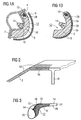
- Fig. 1A is a so-called A-pillar 2 to the passenger compartment of a motor vehicle not shown here to form a gap 4 covered by a pillar trim 6.
- a foamed molded body 8 is arranged, in which run several cables 10.
- the molded body 8 with the cables 10 arranged therein therefore forms a cable harness element 12 as part of a motor vehicle electrical system. Due to the foamed molded body, the cable harness element 12 has a high energy absorption capacity and therefore at the same time also forms an energy absorption element.
- the molded body 8 with the foamed therein cables 10 therefore forms a combination assembly or a combined functional element, which combines the functions of providing electrical lines on the one hand and the energy absorption on the other hand in itself. Due to the combined functional unit, a simple and rapid assembly while simultaneously providing multiple functionality is achieved. Since the shaped body 8 consists of a foamed material, the cable harness element in the event of an accident provides a high level of safety, since the molded body 8 due to its high elasticity can hardly break. In particular, no sharp-edged elements can penetrate into the passenger compartment.
- the cable harness element 12 preferably also has other electrical functional elements, such as e.g. electronic components, which are embedded in particular in the molded body 8 and thereby particularly protected.
- the cable harness element 12 furthermore has a fastening element 14 designed as a snap-in hook, which is a section of the molded body 8.
- the fastening element 14 is pushed through for attachment of the cable harness element 12 through a fastening opening 16 in the A-pillar 2. Due to its elastic construction, the side arms shown in the figure are compressed in this case, which then spread apart again inside the A-pillar 2.
- alternative types of attachment may be provided for attachment of the cable harness element.
- the cable harness element 12 is adapted to the contour of the pillar trim 6, that is, the pillar trim 6 substantially completely conforms to the cable set element 12 directly.
- the pillar trim 6 is shown spaced apart from the molded body 8.
- the pillar trim 6 As an alternative to the configuration of the pillar trim 6 as a separate element to be mounted, it may also be connected to the molded body 8 prior to assembly.
- the cable harness element 12 and the pillar trim 6 in this case form a common structural unit.
- FIGS. 2 and 3 is provided to continue the cable harness element 12 from the A-pillar in the direction of the B-pillar 18. That is, the cable harness element 12 along of the A-pillar 2 connected to the B-pillar 18 body spar 20 along. At the same time, the molded body 8 also extends into a further gap 22 between the outer sheet of a body roof 24 and the inner lining of a headliner 26.
- the area where the cable harness 12 is located is in FIG Fig. 2 indicated by hatching.
- the cable harness element 12 can also be continued in the B pillar or in the body spar 20.
- the molded body 8 of the cable harness element according to the embodiment according to FIG. 2 formed as a continuous and one-piece element.
- the molded body 8 consists of several sections (not shown).
- the individual sections do not abut one another, so that the individual sections are flexibly connected to one another via the cables 10.
- the cables 10 are distributed unevenly in the form of body 8 in the area of the body spar 20.
- two functional zones are formed in the molded body 8, namely on the one hand a cable guide zone 28 and on the other hand an energy absorption zone 30.
- the cable guide zone 28 has a lower energy absorption capacity compared to the energy absorption zone 30.
- the cable guide zone 28 is in this case arranged in an edge region of the shaped body 8.
- Fig. 3 is the cable guide zone 28 in the remote from the passenger compartment rear region of the shaped body 8, which rests on the body spar 20.
- the cable set element 12 has a higher rigidity and also a generally higher hardness than in the remaining region, so that here the energy absorption capacity is lower than in the remaining region, in which the cable set element 12 exclusively of the foamed material of the molding 8 exists.
- the arrangement of the cable guide zone 28 in the edge region or in the rear region ensures that the impact zone of the cable harness element 12 has a high energy absorption capacity exhibit.
- Impact zone is here understood as the area in which, in the event of an accident, the impact of the vehicle occupant is to be expected.
- the design of the cable harness element 12 at the same time as an energy absorption element is preferably also used for other body parts, such as e.g. Doors, used.
- the cable set element 12 Due to the formed as a foam body molding 8, the cable set element 12 at the same time also on a Dämmfunktion. Conveniently, the Jardinelsatzelment 12 is therefore adapted in terms of geometric design of its molded body 8 so on the body side given geometry that at the same time an effective thermal insulation or sound insulation is achieved.
Landscapes
- Engineering & Computer Science (AREA)
- Mechanical Engineering (AREA)
- Body Structure For Vehicles (AREA)
- Vehicle Interior And Exterior Ornaments, Soundproofing, And Insulation (AREA)
- Addition Polymer Or Copolymer, Post-Treatments, Or Chemical Modifications (AREA)
Description
- Die Erfindung betrifft eine Vorrichtung zum Insassenschutz für ein Kraftfahrzeug, insbesondere eine Vorrichtung zur Reduzierung des Kopfverletzungsrisikos bei einem Unfall.
- Zur Reduzierung des Kopfverletzungsrisikos sind unter anderem Kopf- und Seiten-Airbags bekannt, die im Falle eines Unfalls den Aufprall des Kopfes abfangen. Die Airbags decken hierbei jedoch immer nur begrenzte Breiche ab. Ein Problembereich bleibt weiterhin die so genannte A-Säule, also die vorderste Karosseriesäule zwischen Windschutzscheibe und den Vordertüren. Um hier das Verletzungsrisiko gering zu halten, können Energie absorbierende Verkleidungselemente vorgesehen sein. Diese weisen beispielsweise an ihrer vom Fahrgastinnenraum abgewandten Rückseite Rippen auf. Hier besteht jedoch die Gefahr, dass die Verkleidungselemente bei einem Unfall aus ihrer Befestigung gerissen werden und in den Fahrgastinnenraum gelangen. Hierbei können insbesondere auch die Rippen brechen, so dass mitunter scharfkantige Teile zu Verletzungen führen können. Alternativ zu diesen als Energieabsorptionselemente ausgebildeten Verkleidungselementen können auch Energie absorbierende Einlegeteile vorgesehen sein, die beispielsweise zwischen der A-Säule und der Innenverkleidung eingelegt werden. Dies erfordert einen vergleichsweise hohen Montageaufwand. Zusätzlich sind oftmals im Bereich der A-Säule Kabel eines Bordnetzes angeordnet, die in einem getrennten Montageschritt verlegt werden und somit den Montageaufwand erhöhen.
- Aus der
US 6,435,601 B2 ist ein aus mehreren Segmenten zusammensetzbares rohrförmiges und damit hohles Energeiabsorptionselement zu entnehmen. Auch aus derUS 6,293,614 B1 ist ein einen Hohlraum bildendes Energieabsorptionselement zu entnehmen. Beispiele für weitere Energieäbsorptionselemente finden sich darüber hinaus auch in derUS 2001/042988 A1 . - Der Erfindung liegt die Aufgabe zugrunde, eine einfach zu montierende Vorrichtung zum Insassenschutz anzugeben, bei der insbesondere das Kopfverletzungsrisiko gering ist.
- Die Aufgabe wird gemäß der Erfindung durch eine Vorrichtung mit den Merkmalen des Patentanspruchs 1 gelöst. Hierbei ist vorgesehen, dass in den Zwischenraum zwischen einer Karosseriesäule, insbesondere der A-Säule, und einer Säulenverkleidung ein Kabelsatzelement mit Kabeln angeordnet ist, wobei das Kabelsatzelement zugleich als Energieabsorptionselement für den Insassenschutz ausgebildet ist.
- Gemäß Anspruch 1 ist daher vorgesehen, das im Bereich der A-Säule verlegte Kabelsatzelement und das Energieabsorptionselement als eine integrale, einstückige Baueinheit auszubilden. Durch diese Maßnahme ist der Montageaufwand gering gehalten, da lediglich ein Element montiert werden muss. Mit der Montage des Kabelsatzelements wird zugleich auch das Energieabsorptionselement montiert. Das Kabelsatzelement hat insofern eine Doppelfunktion, nämlich einerseits hat es als Teil des Bordnetzes eine elektrische Funktion und andererseits besitzt es aufgrund seiner Ausbildung zur Energieabsorption zugleich eine Schutzfunktion, um im Falle eines Unfalls das Verletzungsrisiko gering zu halten.
- Um einen eventuellen Aufprall des Kopfes möglichst gut dämpfen zu können, weist in einer bevorzugten Weiterbildung das Kabelsatzelement einen geschäumten Formkörper auf, in dem die Kabel geführt sind. Das Kabelsatzelement ist daher von einem vergleichsweise weichen und elastischen Material gebildet. Die Kabel sind hierbei insbesondere vollständig umschäumt. Alternativ hierzu wird das Kabel erst nach der Fertigung des Formkörpers mit diesem verbunden. Hierzu weist der Formkörper bevorzugt eine insbesondere rinnenartige Ausnehmung auf, in die das Kabel z.B. durch Eindrücken oder Einklippsen unverlierbar gehalten ist. Als Schäummaterial können übliche Kunststoff-Materialien verwendet werden, wie sie z. B. Auch für umschäumte Kabelsätze verwendet werden. Die Energie absorbierende Eigenschaften, also beispielsweise die Härte und Elastizität des Formkörpers, können über weite Bereiche entsprechend den gewünschten Anforderungen eingestellt werden. Aufgrund der Verwendung eines geschäumten Formkörpers können bei einem Unfall keine scharfkantigen Teile absplittern und in den Innenraum gelangen, die das Verletzungsrisiko erhöhen würden.
- Zweckdienlicherweise ist das Kabelsatzelement, insbesondere der Formkörper, an die Geometrie der Säulenverkleidung angepasst. Der Formkörper liegt also an der Säulenverkleidung im Wesentlichen an, so dass über den gesamten Bereich der Säuleninnenverkleidung die Schutzfunktion gewährleistet ist.
- Weiterhin ist vorzugsweise vorgesehen, dass das Kabelsatzelement den Zwischenraum zumindest weitgehend ausfüllt. Das Kabelsatzelement, insbesondere der Formkörper, ist daher im Wesentlichen an die Querschnittsgeometrie des Zwischenraums angepasst. Durch diese Anpassung ist zum einen eine Lagefixierung des Kabelsatzelements erreicht. Zum anderen ist durch die vollständige Ausfüllung des Zwischenraums mit dem geschäumten Formkörper eine sehr hohe Energieabsorptionsfähigkeit gegeben.
- Gemäß einer zweckdienlichen Weiterbildung ist das Kabelsatzelement in eine Energieabsorptionszone und eine Kabelführungszone unterteilt. In der Kabelführungszone sind hierbei die Kabel angeordnet, wohingegen die Energieabsorptionszone insbesondere frei von Kabeln ist. Diese Ausgestaltung beruht auf der Überlegung, dass in dem Bereich, in dem Kabel im Formkörper angeordnet sind, dieser üblicherweise eine erhöhte Steifigkeit und Härte aufweist, so dass in diesem Bereich eine geringere Energieabsorptionsfähigkeit vorliegt. Die Energieabsorptionszone ist daher in den Bereichen mit dem größeren Gefahrenpotenzial vorgesehen. Bevorzugt ist hierbei die Kabelführungszone an einem Randbereich des Kabelsatzelementes ausgebildet. Insgesamt ist damit eine unsymmetrische Verteilung und keine Gleichverteilung der Kabel im den Formkörper ausgebildet.
- Im Hinblick auf eine möglichst einfache Montage weist das Kabelsatzelement ein angeformtes Befestigungselement auf, mit dem es mit der Karosseriesäule verbunden ist. Das Befestigungselement ist beispielsweise ein Schnapphaken oder ein Einrastelemeint, welches ein integraler Bestandteil des geschäumten Formkörpers ist.
- Gemäß einer bevorzugten Weiterbildung bilden die Säulenverkleidung und das Kabelsatzelement eine gemeinsame Baueinheit. Die Säulenverkleidung ist hierzu insbesondere unmittelbar auf das Kabelsatzelement aufgebracht. Beispielsweise ist vorgesehen, dass die Säulenverkleidung als zunächst separates Element auf das Kabelsatzelement geklebt wird. Alternativ kann die Säulenverkleidung auch durch unmittelbare Ausgestaltung einer Oberflächenstruktur auf der Oberfläche des Kabelsatzelementes beispielsweise durch Aufspritzen ausgebildet werden. Anstelle des Aufspritzens ist gemäß einer dritten Alternative vorgesehen, dass bereits der Formkörper des Kabelsatzelements eine als Säulenverkleidung geeignete Oberflächenstruktur aufweist. Dies wird bevorzugt durch die Verwendung von zwei unterschiedlichen Materialien, insbesondere Schäumen, für den Formkörper oder durch eine geeignete Oberflächenausgestaltung des formgebenden Werkzeugs für den Formkörper erreicht. Durch Ausgestaltung als gemeinsame Baueinheit ergibt sich eine weitere Montagevereinfachung, so dass vorzugsweise die gesamte Installation im Bereich der A-Säule, nämlich die Anordnung von Kabeln, die Anordnung von Energieabsorptionselementen und die Anordnung der Säuleninnenverkleidung durch die Montage einer einzigen integralen Baueinheit in einem einzigen Arbeitsgang erfolgen kann.
- Gemäß einer zweckdienlichen Weiterbildung ist weiterhin vorgesehen, dass das Kabelsatzelement mit dem als Energieabsorptionselement ausgebildeten Formkörper von der A-Säule in Richtung zu einer weiteren Karosseriesäule, beispielsweise der B- oder C-Säule, weiter geführt ist. Durch diese Maßnahme wird das Schutzelement nicht nur im Bereich der A-Säule sondern auch an der Seite im Bereich eines die Karosseriesäule verbindenden Dachholms weitergeführt. Diese Ausgestaltung ist insbesondere für derartige Kraftfahrzeuge von Vorteil, bei denen kein Seitenairbag vorhanden ist. Zweckdienlicherweise ist hierbei vorgesehen, dass der Formkörper auch zumindest teilweise in einen weiteren Zwischenraum zwischen einem Karosseriedach und einem Dachhimmeln hinein reicht, um im seitlichen Gefahrenbereich eine ausreichende Schutzfunktion zu gewährleisten.
- Bevorzugt weist der Formkörper hierbei mehrere Teilstücke auf. Hierdurch ist die Herstellung vereinfacht. Durch die lose über die Kabel miteinander verbundenen Teilstücke weist das Kabelsatzelement insgesamt auch eine hohe Flexibilität auf, so dass ein einfaches Verlegen ermöglicht ist. Bei der Montage werden hierbei die Kabel oder ein Kabelbündel vorzugsweise in die einzelnen Teilstücke eingelegt. Diese weisen hierzu beispielsweise Ausnehmungen auf oder sind in Längsrichtung geschlitz mit einem innenliegenden Aufnahmekanal ausgebildet, in den die Kabel nach Aufbiegen des Schlitzes eingelegt werden.
- Die Aufgabe wird gemäß der Erfindung weiterhin gelöst durch ein Kabelsatzelement für eine solche Vorrichtung zum Insassenschutz, mit einem Formkörper, in dem Kabel geführt sind, und der zugleich als Energieabsorptionselement für den Insassenschutz ausgebildet ist. Ein derartig vorgefertigtes Kabelsatzelement lässt sich in der Fertigung beim Kraftfahrzeughersteller einfach montieren, wobei durch die Montage eines einzigen Bauelements zugleich mehrere Funktionen implementiert werden.
- Ausführungsbeispiele der Erfindung werden im Folgenden anhand der Figur näher erläutert. Es zeigen jeweils in schematischen, stark vereinfachten Darstellungen:
- Fig. 1A
- einen Querschnitt durch den Bereich einer A-Säule in einem Kraftfahrzeug,
- Fig. 1B
- ein Kabelsatzelement, das zugleich eine Säulenverkleidung bildet,
- Fig. 2
- eine ausschnittsweise perspektivische Darstellung eines Kraftfahrzeugs im Bereich zwischen der A- und der B-Säule, und
- Fig. 3
- eine Querschnittsansicht im Bereich des Karosserieholms zwischen der A-Säule und der B-Säule.
- In den Figuren sind gleich wirkende Teile mit den gleichen Bezugszeichen versehen.
- Gemäß
Fig. 1A ist eine so genannte A-Säule 2 zum Fahrgastinnenraum eines hier nicht näher dargestellten Kraftfahrzeugs unter Ausbildung eines Zwischenraums 4 von einer Säulenverkleidung 6 abgedeckt. Zwischen der Säulenverkleidung 6 und der A-Säule 2 ist ein geschäumter Formkörper 8 angeordnet, in dem mehrere Kabel 10 verlaufen. Der Formkörper 8 mit den darin angeordneten Kabeln 10 bildet daher ein Kabelsatzelement 12 ais Teil eines Kraftfahrzeug-Bordnetzes aus. Aufgrund des geschäumten Formkörpers weist das Kabelsatzelement 12 eine hohe Energieabsorptionsfähigkeit aus und bildet daher zugleich auch ein Energie-Absorptionselement. Der Formkörper 8 mit den darin umschäumten Kabeln 10 bildet daher eine Kombinations-Baueinheit oder ein kombiniertes Funktionselement, welches die Funktionen der Bereitstellung von elektrischen Leitungen einerseits und der Energieabsorption andererseits in sich vereint. Durch die kombinierte Funktionseinheit ist eine einfache und zügige Montage bei gleichzeitiger Bereitstellung der mehrfachen Funktionalität erreicht. Da der Formkörper 8 aus einem geschäumten Material besteht, bietet das Kabelsatzelement im Falle eines Unfalls eine hohe Sicherheit, da der Formkörper 8 aufgrund seiner hohen Elastizität kaum brechen kann. Insbesondere können keine scharfkantigen Elemente in den Fahrgastinnenraum eindringen. - Bevorzugt weist das Kabelsatzelement 12 neben den Kabeln 10 auch weitere elektrische Funktionselemente wie z.B. elektronische Bauteile auf, die insbesondere im Formkörper 8 eingebettet und dadurch besonders geschützt sind.
- Das Kabelsatzelement 12 weist weiterhin ein als Einschnapphaken ausgebildetes Befestigungselement 14 auf, welches ein Teilstück des Formkörpers 8 ist. Das Befestigungselement 14 wird zur Befestigung des Kabelsatzelements 12 durch eine Befestigungsöffnung 16 in der A-Säule 2 hindurchgeschoben. Aufgrund seiner elastischen Ausbildung werden hierbei die in der Figur dargestellten Seitenarme zusammengedrückt, die sich anschließend im Inneren der A-Säule 2 wieder aufspreizen. Zur Befestigung des Kabelsatzelements können natürlich auch alternative Befestigungsarten vorgesehen sein.
- Um die Schutzfunktion über einen möglichst großen Bereich zu gewährleisten, ist das Kabelsatzelement 12 an die Kontur der Säulenverkleidung 6 angepasst, das heißt, die Säulenverkleidung 6 schmiegt sich im Wesentlichen vollständig an das Kabelsatzelement 12 unmittelbar an. In
Fig. 1 ist zur besseren Übersicht die Säulenverkleidung 6 vom Formkörper 8 beabstandet dargestellt. - Alternativ zu der Ausgestaltung der Säulenverkleidung 6 als separat zu montierendes Element kann diese auch vor der Montage mit dem Formkörper 8 verbunden sein. Das Kabelsatzelement 12 und die Säulenverkleidung 6 bilden in diesem Fall eine gemeinsame Baueinheit aus. Im Ausführungsbeispiel der
Fig. 1B ist in einer weitergehenden Vereinfachung die gemeinsame Baueinheit dadurch gebildet, dass die Säulenverkleidung 6 ein Teilstück des Formkörpers 8 selbst ist. Hierbei ist vorgesehen, dass der Formkörper aus zwei unterschiedlichen Schaummaterialien 9a, 9b gebildet ist. Das Schaummaterial 9b bildet die sichtbare Oberfläche und damit die Säulenverkleidung 6. - Gemäß den
Fig. 2 und 3 ist vorgesehen, das Kabelsatzelement 12 von der A-Säule in Richtung zur B-Säule 18 weiterzuführen. Und zwar ist das Kabelsatzelement 12 entlang des die A-Säule 2 mit der B-Säule 18 verbindenden Karosserieholms 20 entlang geführt. Gleichzeitig reicht der Formkörper 8 auch in einen weiteren Zwischenraum 22 zwischen dem Außenblech eines Karosseriedachs 24 und der Innenverkleidung eines Dachhimmels 26 hinein. - Der Bereich, in dem das Kabelsatzelement 12 angeordnet ist, ist in
Fig. 2 durch eine Schraffur angedeutet. Alternativ zu dem dargestellten Bereich kann das Kabelsatzelement 12 auch in der B-Säule oder im Karosserieholm 20 weitergeführt werden. - Der Formkörper 8 des Kabelsatzelements ist gemäß dem Ausführungsbeispiel nach
Figur 2 als ein durchgehendes und einstückiges Element ausgebildet. Alternativ hierzu besteht der Formkörper 8 aus mehreren Teilstücken (nicht dargestellt). So sind beispielsweise für die A-Säule 2, die B-Säule 18, den Karosserieholm 20 und den Zwischenraum 22 jeweils ein Teilstück vorgesehen. Die einzelnen Teilstücke stoßen hierbei in einer Ausführungsvariante nicht aneinander, so dass die einzelnen Teilstücke über die Kabel 10 flexibel miteinander verbunden sind. - Ebenso wie im Bereich der A-Säule 2 gemäß
Fig. 1A sind die Kabel 10 auch im Bereich des Karosserieholms 20 ungleichmäßig im Formkörper 8 verteilt. Durch diese ungleichmäßige Verteilung entstehen im Formkörper 8 zwei Funktionszonen, nämlich einerseits eine Kabelführungszone 28 und andererseits eine Energieabsorptionszone 30. Die Kabelführungszone 28 hat eine im Vergleich zur Energieabsorptionszone 30 geringere Energieabsorptionsfähigkeit. Die Kabelführungszone 28 ist hierbei in einem Randbereich des Formkörpers 8 angeordnet. GemäßFig. 3 befindet sich die Kabelführungszone 28 im vom Fahrgastinnenraum abgewandten rückwärtigen Bereich des Formkörpers 8, der am Karosserieholm 20 anliegt. Im Bereich der Kabelführungszone 28 weist das Kabelsatzelement 12 eine höhere Steifigkeit und auch eine in der Regel höhere Härte als im restlichen Bereich auf, so dass hier die Energieabsorptionsfähigkeit geringer ist als im restlichen Bereich, in dem das Kabelsatzelement 12 ausschließlich aus dem geschäumten Material des Formkörpers 8 besteht. Durch die Anordnung der Kabelführungszone 28 im Randbereich oder im rückwärtigen Bereich ist sichergestellt, dass die Aufprallzone des Kabelsatzelements 12 eine hohe Energieabsorptionsfähigkeit aufweisen. Unter Aufprallzone wir hierbei der Bereich verstanden, in dem im Falle eines Unfalls der Aufprall des Fahrzeug-Insassen zu erwarten ist. - Die Ausgestaltung des Kabelsatzelments 12 zugleich als Energieabsorptionselement wird vorzugsweise auch für andere Korosserieteile, wie z.B. Türen, eingesetzt.
- Aufgrund des als Schaumkörper ausgebildeten Formkörpers 8 weist das Kabelsatzelement 12 zugleich auch eine Dämmfunktion auf. Zweckdienlicherweise wird das Kabelsatzelment 12 im Hinblick auf die geometrische Ausgestaltung seines Formkörpers 8 daher derart an die karosserieseitig vorgegebene Geometrie angepasst, dass zugleich eine wirksame Wärmedämmung oder auch Schalldämmung erzielt wird.
-
- 2
- A-Säule
- 4
- Zwischenraum
- 6
- Säulenverkleidung
- 8
- Formkörper
- 9a, b
- Schaummaterial
- 10
- Kabel
- 12
- Kabelsatzelement
- 14
- Befestigungselement
- 16
- Befestigungsöffnung
- 18
- B-Säule
- 20
- Karosserieholm
- 22
- weiterer Zwischenraum
- 24
- Karosseriedach
- 26
- Dachhimmel
- 28
- Kabelführungszone
- 30
- Energieabsorptionszone
Claims (13)
- Vorrichtung zum Insassenschutz für ein Kraftfahrzeug, mit einem Karosserieteil, das zusammen mit einer Verkleidung einen Zwischenraum (4) begrenzt, wobei in dem Zwischenraum (4) ein Kabelsatzelement (12) angeordnet ist, das einen Formkörper (8) mit darin eingebetteten Kabeln (10) aufweist und, wobei das Kabelsatzelement (12) zugleich als Energieabsorptionselement für den Insassenschutz und als integrale, einstückige Baueinheit ausgebildet ist.
- Vorrichtung nach Anspruch 1, bei dem das Karosserieteil eine Karosseriesäule (2,18), insbesondere A-Säule (2) ist, die zur zu einer Säulenverkleidung (6) den Zwischenraum (4) einschließt.
- Vorrichtung nach Anspruch 1 oder 2, bei der als Formkörper (8) ein geschäumter Formkörper (8) vorgesehen ist.
- Vorrichtung nach Anspruch 2 oder 3, bei der das Kabelsatzelement (12) an die Geometrie der Säulenverkleidung (6) angepasst ist.
- Vorrichtung nach einem der vorhergehenden Ansprüche, bei der das Kabelsatzelement (12) den Zwischenraum (4) zumindest weitgehend ausfüllt.
- Vorrichtung nach einem der vorhergehenden Ansprüche, bei der das Kabelsatzelement (12) in eine Energieabsorptionszone (30) und eine Kabelführungszone (28) unterteilt ist.
- Vorrichtung nach Anspruch 6, bei dem die Kabelführungszone (28) an einem Randbereich des Kabelsatzelements (12) ausgebildet ist.
- Vorrichtung nach einem der vorhergehenden Ansprüche, bei der das Kabelsatzelment (12) ein angeformtes Befestigungselement (14) aufweist, mit dem es mit dem Karosserieteil (2,18) verbunden ist.
- Vorrichtung nach einem der vorhergehenden Ansprüche und Anspruch 2, bei der die Säulenverkleidung (6) und das Kabelsatzelement (12) eine gemeinsame Baueinheit bilden.
- Vorrichtung nach einem der vorhergehenden Ansprüche und Anspruch 2, bei der das Kabelsatzelement (12) von der Karosseriesäule (2) in Richtung zu einer weiteren Karrosseriesäule (18) weitergeführt ist.
- Vorrichtung nach Anspruch 10, bei der der Formkörper (8) zumindest teilweise in einen weiteren Zwischenraum (22) zwischen einem Karosseriedach (24) und einem Dachhimmel (26) geführt ist.
- Vorrichtung nach einem der vorhergehenden, bei der der Formkörper (8) in mehrere einzelne Teilstücke untergliedert ist.
- Kabelsatzelement (12) für eine Vorrichtung nach einem der vorhergehenden Ansprüche, mit einem Formkörper (8) und mit darin eingebetteten Kabel (10), wobei der Formkörper (8) zugleich als Energieabsorptionselement für den Insassenschutz ausgebildet ist.
Applications Claiming Priority (2)
| Application Number | Priority Date | Filing Date | Title |
|---|---|---|---|
| DE10360342A DE10360342B3 (de) | 2003-12-22 | 2003-12-22 | Vorrichtung zum Insassenschutz für ein Kraftfahrzeug |
| PCT/EP2004/012613 WO2005063529A1 (de) | 2003-12-22 | 2004-11-08 | Vorrichtung zum insassenschutz für ein kraftfahrzeug |
Publications (2)
| Publication Number | Publication Date |
|---|---|
| EP1697179A1 EP1697179A1 (de) | 2006-09-06 |
| EP1697179B1 true EP1697179B1 (de) | 2009-11-04 |
Family
ID=34399718
Family Applications (1)
| Application Number | Title | Priority Date | Filing Date |
|---|---|---|---|
| EP04797706A Expired - Lifetime EP1697179B1 (de) | 2003-12-22 | 2004-11-08 | Vorrichtung zum insassenschutz für ein kraftfahrzeug |
Country Status (7)
| Country | Link |
|---|---|
| US (1) | US20060202459A1 (de) |
| EP (1) | EP1697179B1 (de) |
| AT (1) | ATE447511T1 (de) |
| DE (2) | DE10360342B3 (de) |
| ES (1) | ES2335103T3 (de) |
| PT (1) | PT1697179E (de) |
| WO (1) | WO2005063529A1 (de) |
Families Citing this family (2)
| Publication number | Priority date | Publication date | Assignee | Title |
|---|---|---|---|---|
| WO2011133613A1 (en) * | 2010-04-20 | 2011-10-27 | Johnson Controls Technology Company | Plastic vehicle-interior-part with an impact module |
| US11104286B2 (en) * | 2019-07-10 | 2021-08-31 | Ford Global Technologies, Llc | Energy absorption member for vehicle trim |
Family Cites Families (19)
| Publication number | Priority date | Publication date | Assignee | Title |
|---|---|---|---|---|
| US3861711A (en) * | 1972-11-27 | 1975-01-21 | Hoover Ball & Bearing Co | Energy absorbing crash panel |
| DE3016199A1 (de) * | 1980-04-26 | 1981-11-05 | Fa. Carl Freudenberg, 6940 Weinheim | Armaturenbrett- fuer kraftfahrzeuge |
| US5046778A (en) * | 1990-06-29 | 1991-09-10 | The Standard Products Company | Reduced weight vehicle door pillar |
| JP2594345Y2 (ja) * | 1991-02-27 | 1999-04-26 | 池田物産 株式会社 | 車両用ドアトリム |
| US5415554A (en) * | 1993-10-28 | 1995-05-16 | Prince Corporation | Trim panel connecting link |
| FR2720983B1 (fr) * | 1994-06-08 | 1996-08-02 | Plasto Sa | Garniture composite à double paroi pour automobile. |
| GB2293798B (en) * | 1994-10-07 | 1998-03-04 | Toyota Motor Co Ltd | Occupant protecting structures of vehicle body upper portions |
| CA2162778A1 (en) * | 1995-04-19 | 1996-10-20 | James R. Pritchard | Panel with integral energy absorber and air duct |
| GB2308340B (en) * | 1995-12-19 | 2000-02-16 | Rover Group | A vehicle trim panel assembly |
| CA2202226C (en) * | 1996-04-10 | 2000-01-04 | Yoshinori Noritake | Impact energy absorbing structure of vehicle upper portion of automobile |
| JP3292288B2 (ja) * | 1996-12-27 | 2002-06-17 | 矢崎総業株式会社 | 樹脂成形体及び電線の配索方法 |
| CN1080215C (zh) * | 1997-01-08 | 2002-03-06 | 凯萨德工程公司 | 带有一体的电线套紧固件和槽的隔板 |
| WO1998036943A1 (en) * | 1997-02-21 | 1998-08-27 | Lear Corporation | Structural headliner |
| US6126228A (en) * | 1997-09-11 | 2000-10-03 | Lear Automotive Dearborn, Inc. | Wire harness foamed to trim panel |
| US6199941B1 (en) * | 1998-05-08 | 2001-03-13 | Toyota Jidosha Kabushiki Kaisha | Impact energy absorbing structure in upper vehicle body portion and impact energy absorbing member |
| US6086145A (en) * | 1998-07-16 | 2000-07-11 | Textron Automotive Company Inc. | Blow molded headliner |
| US6250711B1 (en) * | 1998-07-31 | 2001-06-26 | Toyota Jidosha Kabushiki Kaisha | Energy absorber securing structure and method |
| US6431638B1 (en) * | 1999-11-15 | 2002-08-13 | The Budd Company | Automobile lift gate |
| JP3607982B2 (ja) * | 2000-05-17 | 2005-01-05 | トヨタ自動車株式会社 | 車体上方構造 |
-
2003
- 2003-12-22 DE DE10360342A patent/DE10360342B3/de not_active Expired - Fee Related
-
2004
- 2004-11-08 EP EP04797706A patent/EP1697179B1/de not_active Expired - Lifetime
- 2004-11-08 ES ES04797706T patent/ES2335103T3/es not_active Expired - Lifetime
- 2004-11-08 WO PCT/EP2004/012613 patent/WO2005063529A1/de not_active Ceased
- 2004-11-08 DE DE502004010330T patent/DE502004010330D1/de not_active Expired - Lifetime
- 2004-11-08 PT PT04797706T patent/PT1697179E/pt unknown
- 2004-11-08 AT AT04797706T patent/ATE447511T1/de not_active IP Right Cessation
-
2006
- 2006-05-08 US US11/429,798 patent/US20060202459A1/en not_active Abandoned
Also Published As
| Publication number | Publication date |
|---|---|
| EP1697179A1 (de) | 2006-09-06 |
| ES2335103T3 (es) | 2010-03-22 |
| PT1697179E (pt) | 2010-01-25 |
| WO2005063529A1 (de) | 2005-07-14 |
| DE10360342B3 (de) | 2005-05-04 |
| ATE447511T1 (de) | 2009-11-15 |
| DE502004010330D1 (de) | 2009-12-17 |
| US20060202459A1 (en) | 2006-09-14 |
Similar Documents
| Publication | Publication Date | Title |
|---|---|---|
| EP0968889B2 (de) | Armaturentafel | |
| DE10050078B4 (de) | Haltegriff-Anordnung für den Fahrgastraum eines Kraftfahrzeuges | |
| WO2000037286A2 (de) | Verkleidungsmodul mit airbag | |
| EP0812739A1 (de) | Airbageinrichtung | |
| DE10140338B4 (de) | Adapter zur Anbringung eines Haltegriffs | |
| WO2008034433A1 (de) | Fahrzeugdach mit einer führungsschiene für ein bewegbares dachteil | |
| DE102021111915A1 (de) | Hybride tragstruktur für ein armaturenbrett eines fahrzeuges sowie hiermit ausgestattetes fahrzeug | |
| DE10360342B3 (de) | Vorrichtung zum Insassenschutz für ein Kraftfahrzeug | |
| DE3128785A1 (de) | Armaturenbrettverkleidung | |
| DE10042419A1 (de) | Dachverkleidung für einen Innenraum eines Fahrzeuges mit einem Seitenaufprallschutz | |
| DE10254349B3 (de) | Innenraumverkleidungselement für ein Kraftfahrzeug | |
| EP1106446B1 (de) | In ein Innenverkleidungsteil für Fahrzeuge integriertes Airbag-System | |
| DE102005015203B4 (de) | Fahrzeugdach mit einer Dachhaut und einer formstabilen Verkleidungsschale | |
| EP1219483B1 (de) | Schachtleiste für eine Fahrzeugtüre | |
| DE102006030504B4 (de) | Stoßfänger für ein Kraftfahrzeug | |
| DE102010036985A1 (de) | Deformationselement | |
| DE10307621B4 (de) | Anordnung zur Verwendung im Bereich eines Dachrahmens eines Kraftfahrzeugs | |
| DE102020102612A1 (de) | Türbaugruppe für ein Kraftfahrzeug | |
| DE102005039125B3 (de) | Instrumententafelanordnung | |
| AT5690U1 (de) | Anordnung zum verbinden der endbereiche zweier innenverkleidungsteile für ein kraftfahrzeug | |
| EP3341244B1 (de) | Fussstütze für ein kraftfahrzeug | |
| DE602004010528T2 (de) | Modulares Armaturenbrett | |
| EP0945329B1 (de) | Crashelement | |
| DE102020102608A1 (de) | Türbaugruppe für ein Kraftfahrzeug | |
| EP1008492A1 (de) | Verkleidungselement für den Innenausbau, insbesondere von Kraftfahrzeugen |
Legal Events
| Date | Code | Title | Description |
|---|---|---|---|
| PUAI | Public reference made under article 153(3) epc to a published international application that has entered the european phase |
Free format text: ORIGINAL CODE: 0009012 |
|
| 17P | Request for examination filed |
Effective date: 20051210 |
|
| AK | Designated contracting states |
Kind code of ref document: A1 Designated state(s): AT BE BG CH CY CZ DE DK EE ES FI FR GB GR HU IE IS IT LI LU MC NL PL PT RO SE SI SK TR |
|
| RAP1 | Party data changed (applicant data changed or rights of an application transferred) |
Owner name: LEONI BORDNETZ-SYSTEME GMBH |
|
| DAX | Request for extension of the european patent (deleted) | ||
| 17Q | First examination report despatched |
Effective date: 20080819 |
|
| GRAP | Despatch of communication of intention to grant a patent |
Free format text: ORIGINAL CODE: EPIDOSNIGR1 |
|
| GRAS | Grant fee paid |
Free format text: ORIGINAL CODE: EPIDOSNIGR3 |
|
| GRAA | (expected) grant |
Free format text: ORIGINAL CODE: 0009210 |
|
| AK | Designated contracting states |
Kind code of ref document: B1 Designated state(s): AT BE BG CH CY CZ DE DK EE ES FI FR GB GR HU IE IS IT LI LU MC NL PL PT RO SE SI SK TR |
|
| REG | Reference to a national code |
Ref country code: GB Ref legal event code: FG4D Free format text: NOT ENGLISH |
|
| REG | Reference to a national code |
Ref country code: CH Ref legal event code: EP |
|
| REG | Reference to a national code |
Ref country code: IE Ref legal event code: FG4D |
|
| REF | Corresponds to: |
Ref document number: 502004010330 Country of ref document: DE Date of ref document: 20091217 Kind code of ref document: P |
|
| REG | Reference to a national code |
Ref country code: PT Ref legal event code: SC4A Free format text: AVAILABILITY OF NATIONAL TRANSLATION Effective date: 20100115 |
|
| REG | Reference to a national code |
Ref country code: SE Ref legal event code: TRGR |
|
| REG | Reference to a national code |
Ref country code: ES Ref legal event code: FG2A Ref document number: 2335103 Country of ref document: ES Kind code of ref document: T3 |
|
| NLV1 | Nl: lapsed or annulled due to failure to fulfill the requirements of art. 29p and 29m of the patents act | ||
| PG25 | Lapsed in a contracting state [announced via postgrant information from national office to epo] |
Ref country code: FI Free format text: LAPSE BECAUSE OF FAILURE TO SUBMIT A TRANSLATION OF THE DESCRIPTION OR TO PAY THE FEE WITHIN THE PRESCRIBED TIME-LIMIT Effective date: 20091104 Ref country code: IS Free format text: LAPSE BECAUSE OF FAILURE TO SUBMIT A TRANSLATION OF THE DESCRIPTION OR TO PAY THE FEE WITHIN THE PRESCRIBED TIME-LIMIT Effective date: 20100304 |
|
| REG | Reference to a national code |
Ref country code: IE Ref legal event code: FD4D |
|
| BERE | Be: lapsed |
Owner name: LEONI BORDNETZ-SYSTEME G.M.B.H. Effective date: 20091130 |
|
| PG25 | Lapsed in a contracting state [announced via postgrant information from national office to epo] |
Ref country code: SI Free format text: LAPSE BECAUSE OF FAILURE TO SUBMIT A TRANSLATION OF THE DESCRIPTION OR TO PAY THE FEE WITHIN THE PRESCRIBED TIME-LIMIT Effective date: 20091104 Ref country code: PL Free format text: LAPSE BECAUSE OF FAILURE TO SUBMIT A TRANSLATION OF THE DESCRIPTION OR TO PAY THE FEE WITHIN THE PRESCRIBED TIME-LIMIT Effective date: 20091104 Ref country code: CY Free format text: LAPSE BECAUSE OF FAILURE TO SUBMIT A TRANSLATION OF THE DESCRIPTION OR TO PAY THE FEE WITHIN THE PRESCRIBED TIME-LIMIT Effective date: 20091104 |
|
| PG25 | Lapsed in a contracting state [announced via postgrant information from national office to epo] |
Ref country code: MC Free format text: LAPSE BECAUSE OF NON-PAYMENT OF DUE FEES Effective date: 20091130 |
|
| REG | Reference to a national code |
Ref country code: CH Ref legal event code: PL |
|
| PG25 | Lapsed in a contracting state [announced via postgrant information from national office to epo] |
Ref country code: RO Free format text: LAPSE BECAUSE OF FAILURE TO SUBMIT A TRANSLATION OF THE DESCRIPTION OR TO PAY THE FEE WITHIN THE PRESCRIBED TIME-LIMIT Effective date: 20091104 Ref country code: IE Free format text: LAPSE BECAUSE OF FAILURE TO SUBMIT A TRANSLATION OF THE DESCRIPTION OR TO PAY THE FEE WITHIN THE PRESCRIBED TIME-LIMIT Effective date: 20091104 Ref country code: EE Free format text: LAPSE BECAUSE OF FAILURE TO SUBMIT A TRANSLATION OF THE DESCRIPTION OR TO PAY THE FEE WITHIN THE PRESCRIBED TIME-LIMIT Effective date: 20091104 Ref country code: DK Free format text: LAPSE BECAUSE OF FAILURE TO SUBMIT A TRANSLATION OF THE DESCRIPTION OR TO PAY THE FEE WITHIN THE PRESCRIBED TIME-LIMIT Effective date: 20091104 Ref country code: BG Free format text: LAPSE BECAUSE OF FAILURE TO SUBMIT A TRANSLATION OF THE DESCRIPTION OR TO PAY THE FEE WITHIN THE PRESCRIBED TIME-LIMIT Effective date: 20100204 |
|
| PG25 | Lapsed in a contracting state [announced via postgrant information from national office to epo] |
Ref country code: SK Free format text: LAPSE BECAUSE OF FAILURE TO SUBMIT A TRANSLATION OF THE DESCRIPTION OR TO PAY THE FEE WITHIN THE PRESCRIBED TIME-LIMIT Effective date: 20091104 Ref country code: CZ Free format text: LAPSE BECAUSE OF FAILURE TO SUBMIT A TRANSLATION OF THE DESCRIPTION OR TO PAY THE FEE WITHIN THE PRESCRIBED TIME-LIMIT Effective date: 20091104 |
|
| PLBE | No opposition filed within time limit |
Free format text: ORIGINAL CODE: 0009261 |
|
| STAA | Information on the status of an ep patent application or granted ep patent |
Free format text: STATUS: NO OPPOSITION FILED WITHIN TIME LIMIT |
|
| 26N | No opposition filed |
Effective date: 20100805 |
|
| PG25 | Lapsed in a contracting state [announced via postgrant information from national office to epo] |
Ref country code: LI Free format text: LAPSE BECAUSE OF NON-PAYMENT OF DUE FEES Effective date: 20091130 Ref country code: GR Free format text: LAPSE BECAUSE OF FAILURE TO SUBMIT A TRANSLATION OF THE DESCRIPTION OR TO PAY THE FEE WITHIN THE PRESCRIBED TIME-LIMIT Effective date: 20100205 Ref country code: BE Free format text: LAPSE BECAUSE OF NON-PAYMENT OF DUE FEES Effective date: 20091130 Ref country code: CH Free format text: LAPSE BECAUSE OF NON-PAYMENT OF DUE FEES Effective date: 20091130 |
|
| PG25 | Lapsed in a contracting state [announced via postgrant information from national office to epo] |
Ref country code: AT Free format text: LAPSE BECAUSE OF NON-PAYMENT OF DUE FEES Effective date: 20091108 |
|
| PG25 | Lapsed in a contracting state [announced via postgrant information from national office to epo] |
Ref country code: LU Free format text: LAPSE BECAUSE OF NON-PAYMENT OF DUE FEES Effective date: 20091108 |
|
| PG25 | Lapsed in a contracting state [announced via postgrant information from national office to epo] |
Ref country code: HU Free format text: LAPSE BECAUSE OF FAILURE TO SUBMIT A TRANSLATION OF THE DESCRIPTION OR TO PAY THE FEE WITHIN THE PRESCRIBED TIME-LIMIT Effective date: 20100505 |
|
| PG25 | Lapsed in a contracting state [announced via postgrant information from national office to epo] |
Ref country code: TR Free format text: LAPSE BECAUSE OF FAILURE TO SUBMIT A TRANSLATION OF THE DESCRIPTION OR TO PAY THE FEE WITHIN THE PRESCRIBED TIME-LIMIT Effective date: 20091104 |
|
| PG25 | Lapsed in a contracting state [announced via postgrant information from national office to epo] |
Ref country code: NL Free format text: LAPSE BECAUSE OF FAILURE TO SUBMIT A TRANSLATION OF THE DESCRIPTION OR TO PAY THE FEE WITHIN THE PRESCRIBED TIME-LIMIT Effective date: 20091104 |
|
| PGFP | Annual fee paid to national office [announced via postgrant information from national office to epo] |
Ref country code: SE Payment date: 20121122 Year of fee payment: 9 Ref country code: IT Payment date: 20121128 Year of fee payment: 9 Ref country code: ES Payment date: 20121122 Year of fee payment: 9 |
|
| PGFP | Annual fee paid to national office [announced via postgrant information from national office to epo] |
Ref country code: GB Payment date: 20131122 Year of fee payment: 10 Ref country code: DE Payment date: 20131125 Year of fee payment: 10 Ref country code: PT Payment date: 20130508 Year of fee payment: 10 |
|
| REG | Reference to a national code |
Ref country code: SE Ref legal event code: EUG |
|
| PG25 | Lapsed in a contracting state [announced via postgrant information from national office to epo] |
Ref country code: SE Free format text: LAPSE BECAUSE OF NON-PAYMENT OF DUE FEES Effective date: 20131109 Ref country code: IT Free format text: LAPSE BECAUSE OF NON-PAYMENT OF DUE FEES Effective date: 20131108 |
|
| PGFP | Annual fee paid to national office [announced via postgrant information from national office to epo] |
Ref country code: FR Payment date: 20141118 Year of fee payment: 11 |
|
| REG | Reference to a national code |
Ref country code: ES Ref legal event code: FD2A Effective date: 20150506 |
|
| REG | Reference to a national code |
Ref country code: PT Ref legal event code: MM4A Free format text: LAPSE DUE TO NON-PAYMENT OF FEES Effective date: 20150508 |
|
| REG | Reference to a national code |
Ref country code: DE Ref legal event code: R119 Ref document number: 502004010330 Country of ref document: DE |
|
| GBPC | Gb: european patent ceased through non-payment of renewal fee |
Effective date: 20141108 |
|
| PG25 | Lapsed in a contracting state [announced via postgrant information from national office to epo] |
Ref country code: PT Free format text: LAPSE BECAUSE OF NON-PAYMENT OF DUE FEES Effective date: 20150508 Ref country code: ES Free format text: LAPSE BECAUSE OF NON-PAYMENT OF DUE FEES Effective date: 20131109 |
|
| PG25 | Lapsed in a contracting state [announced via postgrant information from national office to epo] |
Ref country code: DE Free format text: LAPSE BECAUSE OF NON-PAYMENT OF DUE FEES Effective date: 20150602 Ref country code: GB Free format text: LAPSE BECAUSE OF NON-PAYMENT OF DUE FEES Effective date: 20141108 |
|
| REG | Reference to a national code |
Ref country code: FR Ref legal event code: ST Effective date: 20160729 |
|
| PG25 | Lapsed in a contracting state [announced via postgrant information from national office to epo] |
Ref country code: FR Free format text: LAPSE BECAUSE OF NON-PAYMENT OF DUE FEES Effective date: 20151130 |