EP1695813B1 - A method for manufacturing a wind turbine blade, a wind turbine blade manufacturing facility and use thereof - Google Patents
A method for manufacturing a wind turbine blade, a wind turbine blade manufacturing facility and use thereof Download PDFInfo
- Publication number
- EP1695813B1 EP1695813B1 EP05004010A EP05004010A EP1695813B1 EP 1695813 B1 EP1695813 B1 EP 1695813B1 EP 05004010 A EP05004010 A EP 05004010A EP 05004010 A EP05004010 A EP 05004010A EP 1695813 B1 EP1695813 B1 EP 1695813B1
- Authority
- EP
- European Patent Office
- Prior art keywords
- wind turbine
- turbine blade
- manufacturing
- cavity
- bar
- Prior art date
- Legal status (The legal status is an assumption and is not a legal conclusion. Google has not performed a legal analysis and makes no representation as to the accuracy of the status listed.)
- Expired - Lifetime
Links
- 238000004519 manufacturing process Methods 0.000 title claims abstract description 107
- 238000000034 method Methods 0.000 title claims abstract description 79
- 238000005728 strengthening Methods 0.000 claims description 23
- 239000000853 adhesive Substances 0.000 claims description 18
- 230000001070 adhesive effect Effects 0.000 claims description 18
- 238000007789 sealing Methods 0.000 claims description 14
- 230000001154 acute effect Effects 0.000 claims description 8
- 238000000465 moulding Methods 0.000 claims description 8
- OKTJSMMVPCPJKN-UHFFFAOYSA-N Carbon Chemical compound [C] OKTJSMMVPCPJKN-UHFFFAOYSA-N 0.000 claims description 7
- 229910052799 carbon Inorganic materials 0.000 claims description 7
- 239000000835 fiber Substances 0.000 claims description 6
- 239000002023 wood Substances 0.000 claims description 6
- 239000000805 composite resin Substances 0.000 claims description 5
- 239000003365 glass fiber Substances 0.000 claims description 5
- 239000000463 material Substances 0.000 claims description 5
- 230000006835 compression Effects 0.000 description 7
- 238000007906 compression Methods 0.000 description 7
- 238000003825 pressing Methods 0.000 description 6
- 230000001105 regulatory effect Effects 0.000 description 4
- 230000000694 effects Effects 0.000 description 2
- 239000011152 fibreglass Substances 0.000 description 1
- 239000011796 hollow space material Substances 0.000 description 1
- 238000002347 injection Methods 0.000 description 1
- 239000007924 injection Substances 0.000 description 1
- 239000002184 metal Substances 0.000 description 1
- 239000011347 resin Substances 0.000 description 1
- 229920005989 resin Polymers 0.000 description 1
Images


Classifications
-
- B—PERFORMING OPERATIONS; TRANSPORTING
- B29—WORKING OF PLASTICS; WORKING OF SUBSTANCES IN A PLASTIC STATE IN GENERAL
- B29C—SHAPING OR JOINING OF PLASTICS; SHAPING OF MATERIAL IN A PLASTIC STATE, NOT OTHERWISE PROVIDED FOR; AFTER-TREATMENT OF THE SHAPED PRODUCTS, e.g. REPAIRING
- B29C65/00—Joining or sealing of preformed parts, e.g. welding of plastics materials; Apparatus therefor
- B29C65/48—Joining or sealing of preformed parts, e.g. welding of plastics materials; Apparatus therefor using adhesives, i.e. using supplementary joining material; solvent bonding
-
- B—PERFORMING OPERATIONS; TRANSPORTING
- B29—WORKING OF PLASTICS; WORKING OF SUBSTANCES IN A PLASTIC STATE IN GENERAL
- B29C—SHAPING OR JOINING OF PLASTICS; SHAPING OF MATERIAL IN A PLASTIC STATE, NOT OTHERWISE PROVIDED FOR; AFTER-TREATMENT OF THE SHAPED PRODUCTS, e.g. REPAIRING
- B29C66/00—General aspects of processes or apparatus for joining preformed parts
- B29C66/01—General aspects dealing with the joint area or with the area to be joined
- B29C66/05—Particular design of joint configurations
- B29C66/10—Particular design of joint configurations particular design of the joint cross-sections
- B29C66/11—Joint cross-sections comprising a single joint-segment, i.e. one of the parts to be joined comprising a single joint-segment in the joint cross-section
- B29C66/112—Single lapped joints
-
- B—PERFORMING OPERATIONS; TRANSPORTING
- B29—WORKING OF PLASTICS; WORKING OF SUBSTANCES IN A PLASTIC STATE IN GENERAL
- B29C—SHAPING OR JOINING OF PLASTICS; SHAPING OF MATERIAL IN A PLASTIC STATE, NOT OTHERWISE PROVIDED FOR; AFTER-TREATMENT OF THE SHAPED PRODUCTS, e.g. REPAIRING
- B29C66/00—General aspects of processes or apparatus for joining preformed parts
- B29C66/01—General aspects dealing with the joint area or with the area to be joined
- B29C66/05—Particular design of joint configurations
- B29C66/10—Particular design of joint configurations particular design of the joint cross-sections
- B29C66/13—Single flanged joints; Fin-type joints; Single hem joints; Edge joints; Interpenetrating fingered joints; Other specific particular designs of joint cross-sections not provided for in groups B29C66/11 - B29C66/12
- B29C66/131—Single flanged joints, i.e. one of the parts to be joined being rigid and flanged in the joint area
- B29C66/1312—Single flange to flange joints, the parts to be joined being rigid
-
- B—PERFORMING OPERATIONS; TRANSPORTING
- B29—WORKING OF PLASTICS; WORKING OF SUBSTANCES IN A PLASTIC STATE IN GENERAL
- B29C—SHAPING OR JOINING OF PLASTICS; SHAPING OF MATERIAL IN A PLASTIC STATE, NOT OTHERWISE PROVIDED FOR; AFTER-TREATMENT OF THE SHAPED PRODUCTS, e.g. REPAIRING
- B29C66/00—General aspects of processes or apparatus for joining preformed parts
- B29C66/50—General aspects of joining tubular articles; General aspects of joining long products, i.e. bars or profiled elements; General aspects of joining single elements to tubular articles, hollow articles or bars; General aspects of joining several hollow-preforms to form hollow or tubular articles
- B29C66/51—Joining tubular articles, profiled elements or bars; Joining single elements to tubular articles, hollow articles or bars; Joining several hollow-preforms to form hollow or tubular articles
- B29C66/52—Joining tubular articles, bars or profiled elements
- B29C66/524—Joining profiled elements
-
- B—PERFORMING OPERATIONS; TRANSPORTING
- B29—WORKING OF PLASTICS; WORKING OF SUBSTANCES IN A PLASTIC STATE IN GENERAL
- B29C—SHAPING OR JOINING OF PLASTICS; SHAPING OF MATERIAL IN A PLASTIC STATE, NOT OTHERWISE PROVIDED FOR; AFTER-TREATMENT OF THE SHAPED PRODUCTS, e.g. REPAIRING
- B29C66/00—General aspects of processes or apparatus for joining preformed parts
- B29C66/50—General aspects of joining tubular articles; General aspects of joining long products, i.e. bars or profiled elements; General aspects of joining single elements to tubular articles, hollow articles or bars; General aspects of joining several hollow-preforms to form hollow or tubular articles
- B29C66/51—Joining tubular articles, profiled elements or bars; Joining single elements to tubular articles, hollow articles or bars; Joining several hollow-preforms to form hollow or tubular articles
- B29C66/53—Joining single elements to tubular articles, hollow articles or bars
- B29C66/532—Joining single elements to the wall of tubular articles, hollow articles or bars
-
- B—PERFORMING OPERATIONS; TRANSPORTING
- B29—WORKING OF PLASTICS; WORKING OF SUBSTANCES IN A PLASTIC STATE IN GENERAL
- B29C—SHAPING OR JOINING OF PLASTICS; SHAPING OF MATERIAL IN A PLASTIC STATE, NOT OTHERWISE PROVIDED FOR; AFTER-TREATMENT OF THE SHAPED PRODUCTS, e.g. REPAIRING
- B29C66/00—General aspects of processes or apparatus for joining preformed parts
- B29C66/50—General aspects of joining tubular articles; General aspects of joining long products, i.e. bars or profiled elements; General aspects of joining single elements to tubular articles, hollow articles or bars; General aspects of joining several hollow-preforms to form hollow or tubular articles
- B29C66/51—Joining tubular articles, profiled elements or bars; Joining single elements to tubular articles, hollow articles or bars; Joining several hollow-preforms to form hollow or tubular articles
- B29C66/54—Joining several hollow-preforms, e.g. half-shells, to form hollow articles, e.g. for making balls, containers; Joining several hollow-preforms, e.g. half-cylinders, to form tubular articles
- B29C66/543—Joining several hollow-preforms, e.g. half-shells, to form hollow articles, e.g. for making balls, containers; Joining several hollow-preforms, e.g. half-cylinders, to form tubular articles joining more than two hollow-preforms to form said hollow articles
-
- B—PERFORMING OPERATIONS; TRANSPORTING
- B29—WORKING OF PLASTICS; WORKING OF SUBSTANCES IN A PLASTIC STATE IN GENERAL
- B29C—SHAPING OR JOINING OF PLASTICS; SHAPING OF MATERIAL IN A PLASTIC STATE, NOT OTHERWISE PROVIDED FOR; AFTER-TREATMENT OF THE SHAPED PRODUCTS, e.g. REPAIRING
- B29C66/00—General aspects of processes or apparatus for joining preformed parts
- B29C66/50—General aspects of joining tubular articles; General aspects of joining long products, i.e. bars or profiled elements; General aspects of joining single elements to tubular articles, hollow articles or bars; General aspects of joining several hollow-preforms to form hollow or tubular articles
- B29C66/61—Joining from or joining on the inside
-
- B—PERFORMING OPERATIONS; TRANSPORTING
- B29—WORKING OF PLASTICS; WORKING OF SUBSTANCES IN A PLASTIC STATE IN GENERAL
- B29C—SHAPING OR JOINING OF PLASTICS; SHAPING OF MATERIAL IN A PLASTIC STATE, NOT OTHERWISE PROVIDED FOR; AFTER-TREATMENT OF THE SHAPED PRODUCTS, e.g. REPAIRING
- B29C66/00—General aspects of processes or apparatus for joining preformed parts
- B29C66/50—General aspects of joining tubular articles; General aspects of joining long products, i.e. bars or profiled elements; General aspects of joining single elements to tubular articles, hollow articles or bars; General aspects of joining several hollow-preforms to form hollow or tubular articles
- B29C66/63—Internally supporting the article during joining
- B29C66/636—Internally supporting the article during joining using a support which remains in the joined object
-
- B—PERFORMING OPERATIONS; TRANSPORTING
- B29—WORKING OF PLASTICS; WORKING OF SUBSTANCES IN A PLASTIC STATE IN GENERAL
- B29C—SHAPING OR JOINING OF PLASTICS; SHAPING OF MATERIAL IN A PLASTIC STATE, NOT OTHERWISE PROVIDED FOR; AFTER-TREATMENT OF THE SHAPED PRODUCTS, e.g. REPAIRING
- B29C66/00—General aspects of processes or apparatus for joining preformed parts
- B29C66/70—General aspects of processes or apparatus for joining preformed parts characterised by the composition, physical properties or the structure of the material of the parts to be joined; Joining with non-plastics material
- B29C66/72—General aspects of processes or apparatus for joining preformed parts characterised by the composition, physical properties or the structure of the material of the parts to be joined; Joining with non-plastics material characterised by the structure of the material of the parts to be joined
- B29C66/721—Fibre-reinforced materials
-
- B—PERFORMING OPERATIONS; TRANSPORTING
- B29—WORKING OF PLASTICS; WORKING OF SUBSTANCES IN A PLASTIC STATE IN GENERAL
- B29C—SHAPING OR JOINING OF PLASTICS; SHAPING OF MATERIAL IN A PLASTIC STATE, NOT OTHERWISE PROVIDED FOR; AFTER-TREATMENT OF THE SHAPED PRODUCTS, e.g. REPAIRING
- B29C66/00—General aspects of processes or apparatus for joining preformed parts
- B29C66/80—General aspects of machine operations or constructions and parts thereof
- B29C66/82—Pressure application arrangements, e.g. transmission or actuating mechanisms for joining tools or clamps
- B29C66/824—Actuating mechanisms
- B29C66/8242—Pneumatic or hydraulic drives
- B29C66/82423—Pneumatic or hydraulic drives using vacuum
-
- B—PERFORMING OPERATIONS; TRANSPORTING
- B29—WORKING OF PLASTICS; WORKING OF SUBSTANCES IN A PLASTIC STATE IN GENERAL
- B29C—SHAPING OR JOINING OF PLASTICS; SHAPING OF MATERIAL IN A PLASTIC STATE, NOT OTHERWISE PROVIDED FOR; AFTER-TREATMENT OF THE SHAPED PRODUCTS, e.g. REPAIRING
- B29C66/00—General aspects of processes or apparatus for joining preformed parts
- B29C66/80—General aspects of machine operations or constructions and parts thereof
- B29C66/82—Pressure application arrangements, e.g. transmission or actuating mechanisms for joining tools or clamps
- B29C66/826—Pressure application arrangements, e.g. transmission or actuating mechanisms for joining tools or clamps without using a separate pressure application tool, e.g. the own weight of the parts to be joined
- B29C66/8266—Pressure application arrangements, e.g. transmission or actuating mechanisms for joining tools or clamps without using a separate pressure application tool, e.g. the own weight of the parts to be joined using fluid pressure directly acting on the parts to be joined
- B29C66/82661—Pressure application arrangements, e.g. transmission or actuating mechanisms for joining tools or clamps without using a separate pressure application tool, e.g. the own weight of the parts to be joined using fluid pressure directly acting on the parts to be joined by means of vacuum
-
- B—PERFORMING OPERATIONS; TRANSPORTING
- B29—WORKING OF PLASTICS; WORKING OF SUBSTANCES IN A PLASTIC STATE IN GENERAL
- B29C—SHAPING OR JOINING OF PLASTICS; SHAPING OF MATERIAL IN A PLASTIC STATE, NOT OTHERWISE PROVIDED FOR; AFTER-TREATMENT OF THE SHAPED PRODUCTS, e.g. REPAIRING
- B29C69/00—Combinations of shaping techniques not provided for in a single one of main groups B29C39/00 - B29C67/00, e.g. associations of moulding and joining techniques; Apparatus therefore
- B29C69/004—Combinations of shaping techniques not provided for in a single one of main groups B29C39/00 - B29C67/00, e.g. associations of moulding and joining techniques; Apparatus therefore making articles by joining parts moulded in separate cavities, said parts being in said separate cavities during said joining
-
- B—PERFORMING OPERATIONS; TRANSPORTING
- B29—WORKING OF PLASTICS; WORKING OF SUBSTANCES IN A PLASTIC STATE IN GENERAL
- B29C—SHAPING OR JOINING OF PLASTICS; SHAPING OF MATERIAL IN A PLASTIC STATE, NOT OTHERWISE PROVIDED FOR; AFTER-TREATMENT OF THE SHAPED PRODUCTS, e.g. REPAIRING
- B29C70/00—Shaping composites, i.e. plastics material comprising reinforcements, fillers or preformed parts, e.g. inserts
- B29C70/04—Shaping composites, i.e. plastics material comprising reinforcements, fillers or preformed parts, e.g. inserts comprising reinforcements only, e.g. self-reinforcing plastics
- B29C70/06—Fibrous reinforcements only
-
- B—PERFORMING OPERATIONS; TRANSPORTING
- B29—WORKING OF PLASTICS; WORKING OF SUBSTANCES IN A PLASTIC STATE IN GENERAL
- B29D—PRODUCING PARTICULAR ARTICLES FROM PLASTICS OR FROM SUBSTANCES IN A PLASTIC STATE
- B29D99/00—Subject matter not provided for in other groups of this subclass
- B29D99/0025—Producing blades or the like, e.g. blades for turbines, propellers, or wings
- B29D99/0028—Producing blades or the like, e.g. blades for turbines, propellers, or wings hollow blades
-
- F—MECHANICAL ENGINEERING; LIGHTING; HEATING; WEAPONS; BLASTING
- F03—MACHINES OR ENGINES FOR LIQUIDS; WIND, SPRING, OR WEIGHT MOTORS; PRODUCING MECHANICAL POWER OR A REACTIVE PROPULSIVE THRUST, NOT OTHERWISE PROVIDED FOR
- F03D—WIND MOTORS
- F03D1/00—Wind motors with rotation axis substantially parallel to the air flow entering the rotor
- F03D1/06—Rotors
- F03D1/065—Rotors characterised by their construction elements
- F03D1/0675—Rotors characterised by their construction elements of the blades
-
- B—PERFORMING OPERATIONS; TRANSPORTING
- B29—WORKING OF PLASTICS; WORKING OF SUBSTANCES IN A PLASTIC STATE IN GENERAL
- B29C—SHAPING OR JOINING OF PLASTICS; SHAPING OF MATERIAL IN A PLASTIC STATE, NOT OTHERWISE PROVIDED FOR; AFTER-TREATMENT OF THE SHAPED PRODUCTS, e.g. REPAIRING
- B29C66/00—General aspects of processes or apparatus for joining preformed parts
- B29C66/70—General aspects of processes or apparatus for joining preformed parts characterised by the composition, physical properties or the structure of the material of the parts to be joined; Joining with non-plastics material
- B29C66/72—General aspects of processes or apparatus for joining preformed parts characterised by the composition, physical properties or the structure of the material of the parts to be joined; Joining with non-plastics material characterised by the structure of the material of the parts to be joined
- B29C66/721—Fibre-reinforced materials
- B29C66/7212—Fibre-reinforced materials characterised by the composition of the fibres
-
- B—PERFORMING OPERATIONS; TRANSPORTING
- B29—WORKING OF PLASTICS; WORKING OF SUBSTANCES IN A PLASTIC STATE IN GENERAL
- B29L—INDEXING SCHEME ASSOCIATED WITH SUBCLASS B29C, RELATING TO PARTICULAR ARTICLES
- B29L2031/00—Other particular articles
- B29L2031/08—Blades for rotors, stators, fans, turbines or the like, e.g. screw propellers
- B29L2031/082—Blades, e.g. for helicopters
- B29L2031/085—Wind turbine blades
-
- F—MECHANICAL ENGINEERING; LIGHTING; HEATING; WEAPONS; BLASTING
- F05—INDEXING SCHEMES RELATING TO ENGINES OR PUMPS IN VARIOUS SUBCLASSES OF CLASSES F01-F04
- F05B—INDEXING SCHEME RELATING TO WIND, SPRING, WEIGHT, INERTIA OR LIKE MOTORS, TO MACHINES OR ENGINES FOR LIQUIDS COVERED BY SUBCLASSES F03B, F03D AND F03G
- F05B2230/00—Manufacture
- F05B2230/50—Building or constructing in particular ways
-
- F—MECHANICAL ENGINEERING; LIGHTING; HEATING; WEAPONS; BLASTING
- F05—INDEXING SCHEMES RELATING TO ENGINES OR PUMPS IN VARIOUS SUBCLASSES OF CLASSES F01-F04
- F05B—INDEXING SCHEME RELATING TO WIND, SPRING, WEIGHT, INERTIA OR LIKE MOTORS, TO MACHINES OR ENGINES FOR LIQUIDS COVERED BY SUBCLASSES F03B, F03D AND F03G
- F05B2230/00—Manufacture
- F05B2230/60—Assembly methods
-
- Y—GENERAL TAGGING OF NEW TECHNOLOGICAL DEVELOPMENTS; GENERAL TAGGING OF CROSS-SECTIONAL TECHNOLOGIES SPANNING OVER SEVERAL SECTIONS OF THE IPC; TECHNICAL SUBJECTS COVERED BY FORMER USPC CROSS-REFERENCE ART COLLECTIONS [XRACs] AND DIGESTS
- Y02—TECHNOLOGIES OR APPLICATIONS FOR MITIGATION OR ADAPTATION AGAINST CLIMATE CHANGE
- Y02E—REDUCTION OF GREENHOUSE GAS [GHG] EMISSIONS, RELATED TO ENERGY GENERATION, TRANSMISSION OR DISTRIBUTION
- Y02E10/00—Energy generation through renewable energy sources
- Y02E10/70—Wind energy
- Y02E10/72—Wind turbines with rotation axis in wind direction
-
- Y—GENERAL TAGGING OF NEW TECHNOLOGICAL DEVELOPMENTS; GENERAL TAGGING OF CROSS-SECTIONAL TECHNOLOGIES SPANNING OVER SEVERAL SECTIONS OF THE IPC; TECHNICAL SUBJECTS COVERED BY FORMER USPC CROSS-REFERENCE ART COLLECTIONS [XRACs] AND DIGESTS
- Y02—TECHNOLOGIES OR APPLICATIONS FOR MITIGATION OR ADAPTATION AGAINST CLIMATE CHANGE
- Y02P—CLIMATE CHANGE MITIGATION TECHNOLOGIES IN THE PRODUCTION OR PROCESSING OF GOODS
- Y02P70/00—Climate change mitigation technologies in the production process for final industrial or consumer products
- Y02P70/50—Manufacturing or production processes characterised by the final manufactured product
-
- Y—GENERAL TAGGING OF NEW TECHNOLOGICAL DEVELOPMENTS; GENERAL TAGGING OF CROSS-SECTIONAL TECHNOLOGIES SPANNING OVER SEVERAL SECTIONS OF THE IPC; TECHNICAL SUBJECTS COVERED BY FORMER USPC CROSS-REFERENCE ART COLLECTIONS [XRACs] AND DIGESTS
- Y10—TECHNICAL SUBJECTS COVERED BY FORMER USPC
- Y10T—TECHNICAL SUBJECTS COVERED BY FORMER US CLASSIFICATION
- Y10T29/00—Metal working
- Y10T29/49—Method of mechanical manufacture
- Y10T29/49316—Impeller making
- Y10T29/4932—Turbomachine making
- Y10T29/49321—Assembling individual fluid flow interacting members, e.g., blades, vanes, buckets, on rotary support member
-
- Y—GENERAL TAGGING OF NEW TECHNOLOGICAL DEVELOPMENTS; GENERAL TAGGING OF CROSS-SECTIONAL TECHNOLOGIES SPANNING OVER SEVERAL SECTIONS OF THE IPC; TECHNICAL SUBJECTS COVERED BY FORMER USPC CROSS-REFERENCE ART COLLECTIONS [XRACs] AND DIGESTS
- Y10—TECHNICAL SUBJECTS COVERED BY FORMER USPC
- Y10T—TECHNICAL SUBJECTS COVERED BY FORMER US CLASSIFICATION
- Y10T29/00—Metal working
- Y10T29/49—Method of mechanical manufacture
- Y10T29/49316—Impeller making
- Y10T29/49336—Blade making
- Y10T29/49337—Composite blade
-
- Y—GENERAL TAGGING OF NEW TECHNOLOGICAL DEVELOPMENTS; GENERAL TAGGING OF CROSS-SECTIONAL TECHNOLOGIES SPANNING OVER SEVERAL SECTIONS OF THE IPC; TECHNICAL SUBJECTS COVERED BY FORMER USPC CROSS-REFERENCE ART COLLECTIONS [XRACs] AND DIGESTS
- Y10—TECHNICAL SUBJECTS COVERED BY FORMER USPC
- Y10T—TECHNICAL SUBJECTS COVERED BY FORMER US CLASSIFICATION
- Y10T29/00—Metal working
- Y10T29/49—Method of mechanical manufacture
- Y10T29/49316—Impeller making
- Y10T29/49336—Blade making
- Y10T29/49339—Hollow blade
Definitions
- the invention relates to a wind turbine blade manufacturing facility as specified in the preamble of claim 28, a method for manufacturing a wind turbine blade, wind turbine blades and uses hereof.
- a wind turbine known in the art typically comprises a wind turbine tower and a wind turbine nacelle positioned on top of the tower.
- a wind turbine rotor comprising three wind turbine blades, is connected to the nacelle through a low speed shaft, which extends out of the nacelle front as illustrated on figure 1.
- Wind turbine blades known in the art are typically made of fibre-glass reinforced by metal, wood or carbon fibres.
- the blades are typically manufactured by moulding two blade halves in two independent moulds. When the blade halves are hardened the connecting surfaces are provided with an adhesive and the halves are placed on top of each other. To ensure that the halves are pressed firmly together while the adhesive is hardening, pressure is applied to the moulds, either by pressing the upper mould down onto the bottom mould by means of pneumatic or hydraulic cylinders or by the use of large clamps or by means of straps surrounding the two moulds or blade halves.
- An object of the invention is to provide for a wind turbine blade manufacturing facility and a simple and fast wind turbine blade manufacturing method, which ensures that the joints between the two blade halves becomes substantially uniform.
- a further object of the invention is to provide for wind turbine blade manufacturing facility and a wind turbine blade manufacturing method, where the compression force on the blade parts can be regulated in a simple and fast manner.
- the invention provides for a method for manufacturing a wind turbine blade or a section of a wind turbine blade.
- the method comprises the steps of, establishing at least one first part comprising at least one first wind turbine blade part in at least one first fixating unit, establishing at least one second part comprising at least one second wind turbine blade part in at least one second fixating unit, positioning the at least one first part in contact with, or in close proximity of, the at least one second part, and establishing a pressure below atmospheric pressure, forcing the at least one first wind turbine blade part and the at least one second wind turbine blade part against each other and/or forcing at least one of the wind turbine blade parts against the at least one other.
- pressure below atmospheric pressure or partial vacuum is advantageous, in that it provide means for pressing the at least two parts against each other by a force running uninterrupted and continuously throughout the entire length of the wind turbine blade parts. Furthermore the compression force can be easily regulated, in that a partial vacuum is easy to adjust by regulating the effect of the means for establishing the pressure below atmospheric pressure.
- An aspect of the invention provides for a method for manufacturing a wind turbine blade or a section of a wind turbine blade, wherein said method involves the step of positioning one or more strengthening members on said at least one first wind turbine blade part and/or on said at least one second wind turbine blade part.
- the wind turbine blade with a strengthening member in form of e.g. a beam, a web or a latticework, in that one or more members connecting the first wind turbine blade part and the second wind turbine blade part transversely, provides for a very weight efficient way of strengthening the blade. Furthermore the one or more strengthening members may help the blade maintaining its shape.
- the more complicated the wind turbine blades structure is e.g. in form of a many and/or complicated strengthening members, the more advantageous it is, that the compression force can be distributed evenly and that it can be regulated easily.
- An aspect of the invention provides for a method for manufacturing a wind turbine blade or a section of a wind turbine blade, wherein said at least one first wind turbine blade part, said at least one second wind turbine blade part and one or more strengthening members comprise corresponding contact surfaces.
- the at least one first wind turbine blade part, the at least one second wind turbine blade part and the one or more strengthening members with corresponding contact surfaces, in that it provides the parts with surfaces suitable for attaching the parts to each other.
- An aspect of the invention provides for a method for manufacturing a wind turbine blade or a section of a wind turbine blade, wherein said contact surfaces extents along one or more of the following: leading edge, trailing edge, tip edge and the root.
- An aspect of the invention provides for a method for manufacturing a wind turbine blade or a section of a wind turbine blade, wherein said method involve the step of applying adhesive means to all or some of said contact surfaces before positioning said at least one first part in close proximity of said at least one second part.
- An aspect of the invention provides for a method for manufacturing a wind turbine blade or a section of a wind turbine blade, wherein said pressure below atmospheric pressure is established in at least one cavity formed by said at least one first part and said at least one second part.
- Establishing the partial vacuum in a cavity formed by the first part and the second part is advantageous, in that the partial vacuum can be established in or close to the blade parts which the partial vacuum is to force together. Furthermore it enables the compressing forces, produced by the partial vacuum, to run continuously and uninterrupted throughout the longitudinal extent of wind turbine blade parts.
- cavity is to be understood an opening or a hollow space.
- the cavity does not necessarily have to be closed at all sides or ends, which means that the word cavity also includes gaps, notches, channels, grooves and ducts.
- An aspect of the invention provides for a method for manufacturing a wind turbine blade or a section of a wind turbine blade, wherein said at least one cavity is formed completely or partially by said at least one first fixating unit and said at least one second fixating unit.
- An aspect of the invention provides for a method for manufacturing a wind turbine blade or a section of a wind turbine blade, wherein said at least one cavity is at least two separate cavities e.g. extending along at least one joint by the leading edge and along at least one joint by the trailing edge of said wind turbine blade parts.
- An aspect of the invention provides for a method for manufacturing a wind turbine blade or a section of a wind turbine blade, wherein said at least one cavity extents substantially throughout the longitudinal extent of said wind turbine blade parts.
- Making the cavity extent throughout the entire length of the blade parts is advantageous, in that enables the compressing forces, produced by the partial vacuum, to affect the blade parts throughout the entire length of the wind turbine blade parts.
- An aspect of the invention provides for a method for manufacturing a wind turbine blade or a section of a wind turbine blade, wherein said method involve the step of sealing said at least one cavity before said pressure below atmospheric pressure is established.
- the at least one cavity is formed as e.g. a slit, it is advantageous to seal it, to create a closed space in which a partial vacuum can be established.
- An aspect of the invention provides for a method for manufacturing a wind turbine blade or a section of a wind turbine blade, wherein said sealing involves providing said at least one cavity with one or more sealing means.
- An aspect of the invention provides for a method for manufacturing a wind turbine blade or a section of a wind turbine blade, wherein said sealing involves plugging at least one end of said at least one cavity and connecting at least one vacuum pump directly or indirectly to said at least one other end of said at least one cavity.
- the at least one cavity is formed as e.g. a duct
- a partial vacuum establishing mean such as e.g. a vacuum pump, a vacuum injection pump or a tank in which vacuum is stored.
- An aspect of the invention provides for a method for manufacturing a wind turbine blade or a section of a wind turbine blade, wherein said cavities has an extent of between 10 mm to 1000 mm, preferably 50 mm to 500 mm and most preferred between 100 mm to 350 mm in a direction perpendicular to the longitudinal extent of said wind turbine blade parts and parallel to a line through said leading edge and said trailing edge of said wind turbine blade parts.
- An aspect of the invention provides for a method for manufacturing a wind turbine blade or a section of a wind turbine blade, wherein said establishing of said pressure below atmospheric pressure results in a partial vacuum inside said at least one cavity of between 0,1 Bar to 0,95 Bar, preferably between 0,3 Bar to 0,9 Bar and most preferred between 0,6 Bar to 0,85 Bar, where 0 Bar is absolute vacuum and 1 Bar is proximately atmospheric pressure.
- the present pressure range provides for an advantageous relation between time/energy and function.
- An aspect of the invention provides for a method for manufacturing a wind turbine blade or a section of a wind turbine blade, wherein said a pressure below atmospheric pressure inside said at least one cavity results in a compressing force on the surface of said at least one wind turbine blade parts of between 1.000 N to 10.000.000 N, preferably between 10.000 N to 3.000.000 N and most preferred between 100.000 N to 1.000.000 N.
- An aspect of the invention provides for a method for manufacturing a wind turbine blade or a section of a wind turbine blade, wherein said at least one cavity is formed by the parts of said at least one first fixating unit and said at least one second fixating unit surrounding said at least one first wind turbine blade part and said at least one second wind turbine blade part.
- a partial vacuum in this cavity enables a compressing force distributed over the entire surface of the wind turbine blade parts, which is advantageous if e.g. a compressing force is needed by e.g. a beam in the middle of the blade parts.
- An aspect of the invention provides for a method for manufacturing a wind turbine blade or a section of a wind turbine blade, wherein said at least one first fixating unit and said at least one second fixating unit further forms at least two separate cavities e.g. extending along an at least one joint by the leading edge and along an at least one joint by the trailing edge of said wind turbine blade parts.
- fixating units with further cavities in that it enables the possibility of even more targeted compressing forces.
- An aspect of the invention provides for a method for manufacturing a wind turbine blade or a section of a wind turbine blade, wherein said establishing of said pressure below atmospheric pressure results in a partial vacuum inside said at least one cavity of between 0,1 Bar to 0,995 Bar, preferably between 0,5 Bar to 0,99 Bar and most preferred between 0,8 Bar to 0,98 Bar, where 0 Bar is absolute vacuum and 1 Bar is proximately atmospheric pressure.
- An aspect of the invention provides for a method for manufacturing a wind turbine blade or a section of a wind turbine blade, wherein said a pressure below atmospheric pressure inside said at least one cavity results in a compressing force on the surface of said at least one wind turbine blade parts of between 1.000 N to 10.000.000 N, preferably between 10.000 N to 3.000.000 N and most preferred between 100.000 N to 1.000.000 N.
- An aspect of the invention provides for a method for manufacturing a wind turbine blade or a section of a wind turbine blade, wherein said at least one cavity is formed by said at least one first wind turbine blade part and said at least one second wind turbine blade part.
- wind turbine blades known in the art are hollow and substantially airtight or easily sealable, whereby no further cavities in the fixating units or other are needed.
- An aspect of the invention provides for a method for manufacturing a wind turbine blade or a section of a wind turbine blade, wherein said at least one cavity extents substantially throughout the entire length of said at least one wind turbine blade parts.
- An aspect of the invention provides for a method for manufacturing a wind turbine blade or a section of a wind turbine blade, wherein said at least one cavity is positioned in, or in close proximity of, said contact surfaces.
- An aspect of the invention provides for a method for manufacturing a wind turbine blade or a section of a wind turbine blade, wherein said pressure below atmospheric pressure provides a compressing force that runs uninterrupted throughout the longitudinal extent of said wind turbine blade parts.
- An aspect of the invention provides for a method for manufacturing a wind turbine blade or a section of a wind turbine blade, wherein said compressing force further is uniform throughout the longitudinal extent of said wind turbine blade parts.
- An aspect of the invention provides for a method for manufacturing a wind turbine blade or a section of a wind turbine blade, wherein said method involve the step of moulding said at least one first wind turbine blade part and said at least one second wind turbine blade part around at least one fixating edge on said at least one first fixating unit and said at least one second fixatitlg unit.
- Moulding the blade parts around at least one fixating edge is advantageous, in that it fixates the edges of the blade parts and thereby maintains the contact surfaces position constant, simplifying both the process of adding adhesive and the process of establishing partial vacuum.
- An aspect of the invention provides for a method for manufacturing a wind turbine blade or a section of a wind turbine blade, wherein said at least one fixating edge on said at least one first fixating unit or on said at least one second fixating unit is made in an acute angle and said at least one other fixating edge on said at least one first fixating unit or on said at least one second fixating unit is made substantially rectangular.
- Making at least one fixating edge in an acute angle is advantageous, in that it helps to maintain a blade parts position in the fixating unit, particularly during the handling process, if said blade part is an upper part to be positioned onto of a corresponding bottom part.
- Making at least one other fixating edge rectangular is advantageous, if this edge is a part of a fixating unit containing a bottom blade part, in that it enables unresisting removal of the complete blade or section of a blade.
- An aspect of the invention provides for a method for manufacturing a wind turbine blade or a section of a wind turbine blade, wherein at least one of said at least one first fixating unit and said at least one second fixating unit is a mould, in which said at least one first and second wind turbine blade parts are moulded.
- moulds as the fixating units, in that it simplifies the manufacturing process by reducing handling.
- the invention further provides for a wind turbine blade manufacturing facility, comprising at least one first part including at least one first fixating unit, adapted for fixating at least one first wind turbine blade part, at least one second part comprising at least one second fixating unit, adapted for fixating at least one second wind turbine blade part, and means for positioning said at least one first part in contact with or in close proximity of said at least one second part.
- the manufacturing facility is characterized in that, it further comprise means for establishing a pressure below atmospheric pressure, forcing said at least one first wind turbine blade part and said at least one second wind turbine blade part against each other and/or forcing at least one of the wind turbine blade parts against the at least one other.
- Using means such as a vacuum pump, for evacuating air to establish a pressure below atmospheric pressure, is advantageous in that, it is easy to regulate the effect of e.g. a vacuum pump and thereby it is easy to regulate the force pressing the blade parts together.
- wind turbine blade manufacturing facility also includes facilities to manufacture sections of a wind turbine blade.
- said facility comprise means for positioning one or more strengthening members on said at least one first wind turbine blade part and/or on said at least one second wind turbine blade part.
- wind turbine blade is to be provided with one or more strengthening members, it is advantageous to equip the facility with means for handling these members.
- said at least one first wind turbine blade part, said at least one second wind turbine blade part and one or more strengthening members comprise corresponding contact surfaces.
- said contact surfaces extents along one or more of the following: leading edge, trailing edge, tip edge and the root.
- said facility comprise means for applying an adhesive to all or some of said contact surfaces.
- contact surfaces are to be provided with an adhesive, it is advantageous to equip the facility with means for applying this adhesive.
- said at least one first part and said at least one second part forms at least one cavity when positioned in contact with or in close proximity of each other.
- said at least one first fixating unit and said at least one second fixating unit completely or partially forms at least one cavity when positioned in contact with or in close proximity of each other.
- said at least one cavity extents substantially throughout the longitudinal extent of said wind turbine blade parts.
- said at least one cavity is at least two separate cavities . e.g. extending along at least one joint by the leading edge and along at least one joint by the trailing edge of said wind turbine blade parts.
- said facility comprise means for sealing said at least one cavity.
- said means for sealing comprise one or more plugs for plugging at least one end of said at least one cavity and at least one vacuum pump for connecting to said at least one other end of said at least one cavity.
- said cavities has an extent of between 10 mm to 1000 mm, preferably 50 mm to 500 mm and most preferred between 100 mm to 350 mm in a direction perpendicular to the longitudinal extent of said wind turbine blade parts and parallel to a line through said leading edge and said trailing edge of said wind turbine blade parts.
- said means for establishing a pressure below atmospheric pressure are capable of producing a partial vacuum, inside said at least one cavity, of between 0,1 Bar to 0,95 Bar, preferably between 0,3 Bar to 0,9 Bar and most preferred between 0,6 Bar to 0,85 Bar, where 0 Bar is absolute vacuum and 1 Bar is proximately atmospheric pressure.
- said facility comprise means for establishing a pressure below atmospheric pressure inside said at least one cavity which results in a compressing force on the surface of said at least one wind turbine parts of between 1.000 N to 10.000.000 N, preferably between 10.000 N to 3.000.000 N and most preferred between 100.000 N to 1.000.000 N.
- said at least one cavity is formed by the parts of said at least one first fixating unit and said at least one second fixating unit surrounding said at least one first wind turbine blade part and said at least one second wind turbine blade part.
- said at least one first fixating unit and said at least one second fixating unit further forms at least two separate cavities e.g. extending along an at least one joint by the leading edge and along an at least one joint by the trailing edge of said wind turbine blade parts.
- said means for establishing a pressure below atmospheric pressure are capable of producing a partial vacuum, inside said at least one cavity, of between 0,1 Bar to 0,995 Bar, preferably between 0,5 Bar to 0,99 Bar and most preferred between 0,8 Bar to 0,98 Bar, where 0 Bar is absolute vacuum and 1 Bar is proximately atmospheric pressure.
- said facility comprise means for establishing a pressure below atmospheric pressure inside said at least one cavity which results in a compressing force on the surface of said at least one wind turbine parts of between 1.000 N to 10.000.000 N, preferably between 10.000 N to 3.000.000 N and most preferred between 100.000 N to 1.000.000 N.
- said at least one cavity is formed by said at least one first wind turbine blade part and said at least one second wind turbine blade part.
- said at least one cavity extents substantially throughout the entire length of said at least one wind turbine blade parts.
- said at least one cavity is positioned in, or in close proximity of, said contact surfaces.
- said means for providing a pressure below atmospheric pressure provides a compressing force that runs uninterrupted throughout the longitudinal extent of said wind turbine blade parts.
- said compressing force further is uniform throughout the longitudinal extent of said wind turbine blade parts.
- said at least one first fixating unit and said at least one second fixating unit is provided with at least one fixating edge for moulding at least one edge of said at least one first wind turbine blade part and said at least one second wind turbine blade part around.
- said at least one fixating edge on said at least one first fixating unit or on said at least one second fixating unit is made in an acute angle and said at least one other fixating edge on said at least one first fixating unit or on said at least one second fixating unit is made substantially rectangular.
- At least one of said at least one first fixating unit and said at least one second fixating unit is a mould, in which said at least one first and second wind turbine blade parts are moulded.
- the invention further provides for a method for manufacturing a wind turbine blade, where said wind turbine blade is made of carbon fibre reinforced wood, a glass fibre and resin composite or any other material suitable for making large wind turbine blades.
- the invention further provides for use of a wind turbine blade manufacturing facility, where said wind turbine blade is made of carbon fibre reinforced wood, a glass fibre and resin composite or any other material suitable for making large wind turbine blades.
- Fig. 1 illustrates a modem wind turbine 1, comprising a tower 2 and a wind turbine nacelle 3 positioned on top of the tower 2.
- the wind turbine rotor 4 comprising three wind turbine blades 5, is connected to the nacelle 3 through the low speed shaft which extends out of the nacelle 3 front.
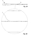
- Fig. 2A illustrates a wind turbine blade 5 as seen from the side.
- a wind turbine blade 5 known in the art is made of two substantially identical blade halves connected in a joint 6 by means of adhesive.
- the known method is to apply pressure to the blade halves, either by means of straps tightened around the halves, by means of hydraulic or pneumatic actuators or other methods applying pressure in a number of specific points.
- Fig. 2B illustrates a section of the same wind turbine blade 5 as illustrated in fig- 2A, where the wave like shape of the joint 7 is clearly shown.
- Fig. 3 illustrates a wind turbine blade, as seen from the front.
- the wind turbine blade 5 comprises a leading edge 17, a trailing edge 18, a tip edge 19 and a root 20.
- the blade is typically hollow, except for one or more strengthening members 16 extending substantially the entire length of the blade 5 or part of the blades 5 length.
- a wind turbine blade 5 known in the art is typically made of a glass fibre and resin composite reinforced by carbon fibre, carbon fibre reinforced wood or a combination hereof.
- Fig. 4 illustrates a vertical cross section a first part 8 and a second part 11.
- the first part 8 comprises a first wind turbine blade part 9 placed in a first fixating unit 10, which in this case is the mould in which the blade part 9 is made.
- the second part 11 comprises a second wind turbine blade part 12 placed in a second fixating unit 13, which also is the mould in which the blade part 12 is moulded.
- the two substantially symmetrical parts 8, 11 are placed beside each other with the outer surfaces of the blade parts 9, 12 facing down, during the moulding of the blade parts 9,12.
- the contact surfaces 15 are provided with an adhesive, and the second part 11 is rotated and positioned on top of the first part 8, e.g. by means of some sort of a crane (like a gantry crane) or special-build rotating and positioning equipment.
- the adhesive could also be provided to the contact surfaces after the blade parts 9, 12 are brought in contact with each other or in close proximity of each other.
- the second part 11 is placed on top of the first part 8, but in another embodiment of the invention the first part 8 could be placed on top of the second part 11, or the two parts 8, 11 could be placed against each other in e.g. a vertical position.
- the parts 8, 11 are for moulding an entire wind turbine blade 5, but since wind turbines 1 are getting bigger and bigger, the wind turbine blades 5 are gradually getting too long to be transported in one piece.
- the blade 5 would then be manufactured as sections, which then are to be assembled at the wind turbine mounting site.
- the parts 8, 11 and the entire manufacturing facility could therefore be for manufacturing sections of wind turbine blades 5.
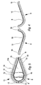
- Fig 5. illustrates the second part 11 placed on top of the first part 8 making the two parts 8, 11 abut at the contact surfaces 15 on the blade parts 9, 12.
- two strengthening members 16 are attached to the first blade part 9 e.g. by means of adhesive.
- the strengthening members 16 constitutes cross braces making the blade 5 more rigid and helping the blade maintain its shape.
- the blade 5 could be provided with more than two juxtaposed strengthening members 16 e.g. three, four or six members, and all or some of the members 16 could be placed inside the blade 5 after the two parts 8, 11 are placed on top of each other, or the wind turbine blade parts 9, 12 could be made so strong that no strengthening members 16 are needed.
- more than two juxtaposed strengthening members 16 e.g. three, four or six members, and all or some of the members 16 could be placed inside the blade 5 after the two parts 8, 11 are placed on top of each other, or the wind turbine blade parts 9, 12 could be made so strong that no strengthening members 16 are needed.
- the blade 5 could also be provided with only one strengthening member 16 e.g. in form of a beam.
- This beam could be the member carrying the entire blade 5, and the blade parts 9, 12 could then just be relatively thin shells, mainly provided for giving the blade its aerodynamic shape.
- the two mould parts 10, 13 forms a cavity 14a which is substantially closed all the way around, except at the root of the blade 5, where means for evacuating air, such as a vacuum pump, can be attached to the mould parts 10, 13.
- means for evacuating air such as a vacuum pump
- the air outside the two mould parts 10, 13 will press against the mould parts 10, 13.
- These mould parts 10, 13 will then press against the entire outer surface of the blade parts 9, 12 and particularly against the contact surfaces 15 both at the joint 6 by the leading edge 17 and the trailing edge 18, but also by the strengthening members 16 contact surfaces 15.
- the compression force produced by the partial vacuum is not uniform either, since the magnitude of the pressure is defined by the size of the vacuum, multiplied by the projected area it affects. But even though the load is not uniform, it still runs uninterrupted throughout the entire length of the blade 5 and the variation in compression force is relatively small and distributed over relatively large distances.
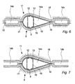
- Fig. 6 illustrates a vertical cross section of a first part 8 and a second part 11 as seen from the root 20 of the blade.
- the fixating units 10, 13, which in this case are the moulds in which the blade parts 9, 12 are made forms a part of two additional cavities 14b running along the joints 6, at the leading edge 17 and the trailing edge 18 in the entire length of the blade 5.
- Sealing means 22, such as a plate or a stiff tarpaulin, is provided to these cavities 14b to seal the sides, a plug is provided to seal the one end of the cavity 14b and partial vacuum providing means are attached to the other ends.
- the two additional cavities 14b could be joined in one end, so that only one opening needs to be plugged, this opening being positioned next to the opening, where the pump means are to be attached e.g. in the root 20 end of the blade 5.
- the fixating units 10, 13 could be made in a way that, except for the opening for attaching e.g. a vacuum pump, the cavities 14b would be completely sealed, when the two parts 8, 11 are brought in contact with each other.
- the cavities 14b are substantially uniform throughout the entire length of the blade 5, producing a substantially uniform and uninterrupted compressing force throughout the entire length of the blade 5, but in another embodiment the projected area of the cavities 14b could vary throughout the length of the blade 5, to produce a varying load adapted to the specific need.
- Fig. 7 illustrates a vertical cross section of a similar embodiment of the invention as illustrated in fig. 6, as seen from the root 20 of the blade.
- the fixating units 10,13 forms a part of two additional cavities 14b the partial vacuum is established inside the part of the two fixating units 10, 13 surrounding the blade parts 9, 12.
- the partial vacuum could be established in both the part of the two fixating units 10, 13 surrounding the blade parts 9, 12 and in the additional cavities 14b.
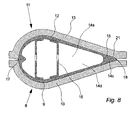
- Fig. 8 illustrates a vertical cross section of a first part 8 and a second part 11, comprising grooves 21 embedded in the second wind turbine blade parts 12 contact surfaces 15, as seen from the root 20 of the blade 5.
- the partial vacuum is established inside these grooves 21, providing the compression force exactly where it is needed and independent of fixating units 10, 13 or the design thereof.
- the partial vacuum could be established inside the entire cavity 14d formed by the first wind turbine blade part 9 and the second wind turbine blade part 9.
- Fig. 9 illustrates a section of a vertical cross section of a first part 8 and a second part 11 comprising fixating edges 23, 24, as seen from the root 20 of the blade 5. To ensure that the contact surfaces 15 maintain their positions during the hardening of the blade parts 9, 12 and the succeeding handling the edges of the blade parts 9, 12 are moulded around fixating edges 23, 24 on the fixating units 10, 13.
- the second wind turbine blade part 12 is moulded around an acute angled fixating edge 23 on the second fixating unit 13 to help fixate the blade part 12 during a rotation and positioning on top of the first part 8.
- the first wind turbine blade part 9 is moulded around a rectangular fixating edge 24 on the first fixating unit 10, in that a rectangular fixating edge 24 makes it easier to remove the blade 5 from the fixating unit 10. The excess material can be cut of during the process of giving the blade 5 its final finish.
- both fixating edges 23, 24 could be made in an acute angle or both could be rectangular.
Landscapes
- Engineering & Computer Science (AREA)
- Mechanical Engineering (AREA)
- Physics & Mathematics (AREA)
- Chemical & Material Sciences (AREA)
- Fluid Mechanics (AREA)
- Life Sciences & Earth Sciences (AREA)
- Sustainable Development (AREA)
- Sustainable Energy (AREA)
- Combustion & Propulsion (AREA)
- General Engineering & Computer Science (AREA)
- Composite Materials (AREA)
- Wind Motors (AREA)
- Turbine Rotor Nozzle Sealing (AREA)
Priority Applications (14)
| Application Number | Priority Date | Filing Date | Title |
|---|---|---|---|
| ES05004010T ES2289613T3 (es) | 2005-02-24 | 2005-02-24 | Metodo para fabricar una pala de turbina eolica, instalacion de fabricacion de pala de turbina eolica y uso de la misma. |
| PT05004010T PT1695813E (pt) | 2005-02-24 | 2005-02-24 | Método de fabricação de uma pá de turbina eólica, instalação de fabricação de pás de turbina eólica e sua utilização. |
| AT05004010T ATE364494T1 (de) | 2005-02-24 | 2005-02-24 | Verfahren zur herstellung eines windturbinenblatts, eine produktionsanlage von windturbinenblättern und verwendung hiervon |
| DK05004010T DK1695813T3 (da) | 2005-02-24 | 2005-02-24 | Fremgangsmåde til fremstilling af en vindmöllevinge, et fremstillingsanlæg til vindmöllevinger og anvendelse heraf |
| DE602005001391T DE602005001391T2 (de) | 2005-02-24 | 2005-02-24 | Verfahren zur Herstellung eines Windturbinenblatts, eine Produktionsanlage von Windturbinenblättern und Verwendung hiervon |
| EP05004010A EP1695813B1 (en) | 2005-02-24 | 2005-02-24 | A method for manufacturing a wind turbine blade, a wind turbine blade manufacturing facility and use thereof |
| US11/087,472 US7895746B2 (en) | 2005-02-24 | 2005-03-23 | Method for manufacturing a wind turbine blade |
| PCT/DK2006/000103 WO2006089550A2 (en) | 2005-02-24 | 2006-02-22 | A method for manufacturing a wind turbine blade, a wind turbine blade manufacturing facility, wind turbine blades and uses hereof |
| KR1020077021561A KR20080004468A (ko) | 2005-02-24 | 2006-02-22 | 풍력 터빈 블레이드를 제조하는 방법, 풍력 터빈 블레이드제조 설비, 풍력 터빈 블레이드 및 그것의 이용 |
| AU2006218238A AU2006218238A1 (en) | 2005-02-24 | 2006-02-22 | A method for manufacturing a wind turbine blade, a wind turbine blade manufacturing facility, wind turbine blades and uses hereof |
| CNB2006800060608A CN100566983C (zh) | 2005-02-24 | 2006-02-22 | 制造风轮机叶片的方法、风轮机叶片制造设备、风轮机叶片及其使用 |
| CA002597768A CA2597768A1 (en) | 2005-02-24 | 2006-02-22 | A method for manufacturing a wind turbine blade, a wind turbine blade manufacturing facility, wind turbine blades and uses hereof |
| MX2007009348A MX2007009348A (es) | 2005-02-24 | 2006-02-22 | Un metodo para fabricar un alabe de turbina eolica, una instalacion para la fabricacion de alabes de turbina eolica, alabes de turbina eolica y sus usos. |
| JP2007556490A JP2008531902A (ja) | 2005-02-24 | 2006-02-22 | 風力タービン翼を製造する方法、風力タービン翼製造設備、風力タービン翼、及びその使用 |
Applications Claiming Priority (1)
| Application Number | Priority Date | Filing Date | Title |
|---|---|---|---|
| EP05004010A EP1695813B1 (en) | 2005-02-24 | 2005-02-24 | A method for manufacturing a wind turbine blade, a wind turbine blade manufacturing facility and use thereof |
Publications (2)
| Publication Number | Publication Date |
|---|---|
| EP1695813A1 EP1695813A1 (en) | 2006-08-30 |
| EP1695813B1 true EP1695813B1 (en) | 2007-06-13 |
Family
ID=34933917
Family Applications (1)
| Application Number | Title | Priority Date | Filing Date |
|---|---|---|---|
| EP05004010A Expired - Lifetime EP1695813B1 (en) | 2005-02-24 | 2005-02-24 | A method for manufacturing a wind turbine blade, a wind turbine blade manufacturing facility and use thereof |
Country Status (14)
Cited By (2)
| Publication number | Priority date | Publication date | Assignee | Title |
|---|---|---|---|---|
| EP2308670A1 (en) | 2009-10-12 | 2011-04-13 | Vestas Wind Systems A/S | Fixing device |
| US10569485B2 (en) | 2013-12-23 | 2020-02-25 | Vestas Wind Systems A/S | Fixing device for fixating a segment of a wind turbine blade to a mould |
Families Citing this family (63)
| Publication number | Priority date | Publication date | Assignee | Title |
|---|---|---|---|---|
| US7517198B2 (en) | 2006-03-20 | 2009-04-14 | Modular Wind Energy, Inc. | Lightweight composite truss wind turbine blade |
| CN100412356C (zh) * | 2006-08-31 | 2008-08-20 | 东莞中德风电能源有限公司 | 风能发电机的叶片的制造方法 |
| US7824592B2 (en) * | 2006-09-22 | 2010-11-02 | General Electric Company | Bond line forming method |
| US7908923B2 (en) * | 2006-12-07 | 2011-03-22 | Siemens Aktiengesellschaft | Method of non-destructively testing a work piece and non-destructive testing arrangement |
| DK2126349T3 (en) | 2007-02-27 | 2018-08-27 | Vestas Wind Sys As | A WINDMILL CLEANING AND PROCEDURE FOR COLLECTING A WINDMILL CLEANING |
| US7895745B2 (en) | 2007-03-09 | 2011-03-01 | General Electric Company | Method for fabricating elongated airfoils for wind turbines |
| US20090070977A1 (en) * | 2007-09-13 | 2009-03-19 | General Electric Company | Jig And Fixture For Wind Turbine Blade |
| US8123488B2 (en) * | 2007-09-17 | 2012-02-28 | General Electric Company | System and method for joining turbine blades |
| US20090146433A1 (en) * | 2007-12-07 | 2009-06-11 | General Electric Company | Method and apparatus for fabricating wind turbine components |
| US8171633B2 (en) * | 2007-12-19 | 2012-05-08 | General Electric Company | Method for assembling a multi-segment wind turbine blade |
| US7740453B2 (en) * | 2007-12-19 | 2010-06-22 | General Electric Company | Multi-segment wind turbine blade and method for assembling the same |
| DK2106900T3 (da) * | 2008-04-03 | 2012-07-09 | Siemens Ag | Form og fremgangsmåde til vakuumunderstøttet resinoverføringsstøbning |
| US20110116935A1 (en) * | 2008-05-16 | 2011-05-19 | Xemc Darwind B.V. | method of manufacturing a turbine blade half, a turbine blade half, a method of manufacturing a turbine blade, and a turbine blade |
| NL1035861C (en) * | 2008-08-25 | 2010-03-11 | Darwind Holding B V | A method of manufacturing a turbine blade half, a turbine blade half, a method of manufacturing a turbine blade, and a turbine blade. |
| EP2153964A1 (en) * | 2008-08-14 | 2010-02-17 | Lm Glasfiber A/S | A method of manufacturing a wind turbine blade comprising steel wire reinforced matrix material |
| BRPI0922749B1 (pt) | 2008-12-05 | 2021-01-05 | Modular Wind Energy, Inc. | pá de turbina eólica |
| EP2226186A1 (en) * | 2009-03-06 | 2010-09-08 | Lm Glasfiber A/S | Method and manufacturing line for manufacturing wind turbine blades |
| CN201357535Y (zh) * | 2009-03-13 | 2009-12-09 | 苏州红枫风电模具有限公司 | 用于大型组合式模具的可调整的对齐装置 |
| US7854594B2 (en) * | 2009-04-28 | 2010-12-21 | General Electric Company | Segmented wind turbine blade |
| US8753091B1 (en) | 2009-05-20 | 2014-06-17 | A&P Technology, Inc. | Composite wind turbine blade and method for manufacturing same |
| DK2255957T3 (da) | 2009-05-25 | 2013-10-21 | Lm Wp Patent Holding As | En fremgangsmåde til fremstilling af et kompositlegeme med et præfremstillet forstærkningslegeme |
| DE102009024324A1 (de) * | 2009-05-29 | 2010-12-02 | Nordex Energy Gmbh | Verfahren und Vorrichtung zur Montage eines Rotorblatts für eine Windenergieanlage |
| EP2275673B1 (en) * | 2009-07-17 | 2018-01-24 | Vestas Wind Systems A/S | Manufacturing WTG blade having a spar |
| KR100935178B1 (ko) * | 2009-07-21 | 2010-01-06 | 유경연 | 팬 블레이드 및 그의 제조방법 |
| US20120131782A1 (en) * | 2009-07-23 | 2012-05-31 | Vestas Wind Systems A/S | Method for making a mould for a wind turbine rotor blade |
| EP2295235B1 (en) * | 2009-08-20 | 2013-07-03 | Siemens Aktiengesellschaft | Fiber reinforced plastic-structure and a method to produce the fiber reinforced plastic-structure |
| CN201552691U (zh) * | 2009-09-10 | 2010-08-18 | 苏州红枫风电模具有限公司 | 风轮机叶片模具侧面形状调节装置 |
| CN102022254B (zh) * | 2009-09-23 | 2014-12-17 | 固瑞特模具(太仓)有限公司 | 风轮机叶片及其生产方法 |
| DE102009058101A1 (de) * | 2009-12-12 | 2011-06-16 | Bayer Materialscience Ag | Verwendung von Schichtaufbauten in Windkraftanlagen |
| DK2365212T3 (en) * | 2010-03-12 | 2016-08-15 | Siemens Ag | Device and method for rebuilding a wind turbine |
| US9500179B2 (en) | 2010-05-24 | 2016-11-22 | Vestas Wind Systems A/S | Segmented wind turbine blades with truss connection regions, and associated systems and methods |
| US8043066B2 (en) * | 2010-06-08 | 2011-10-25 | General Electric Company | Trailing edge bonding cap for wind turbine rotor blades |
| ES2600641T3 (es) * | 2010-07-21 | 2017-02-10 | Siemens Aktiengesellschaft | Conjunto de molde y método de cierre de un conjunto de molde |
| ES2387662B1 (es) * | 2010-09-28 | 2013-05-27 | Manuel Torres Martínez | Instalación para ensamblado de estructuras de materiales compuestos. |
| DE102010042327A1 (de) * | 2010-10-12 | 2012-04-12 | Repower Systems Se | Fertigung eines Rotorblattes einer Windenergieanlage |
| EP2441951B1 (en) * | 2010-10-13 | 2017-04-26 | Siemens Aktiengesellschaft | Method for manufacturing a wind turbine rotor blade |
| GB2484941A (en) * | 2010-10-26 | 2012-05-02 | Vestas Wind Sys As | Material with radar absorbing circuit analogue elements for surface application to a wind turbine component |
| US8425196B2 (en) * | 2011-01-28 | 2013-04-23 | General Electric Company | Wind turbine blades with a hardened substrate construction |
| ES2387432B1 (es) * | 2011-02-25 | 2013-07-29 | Francisco Javier Garcia Castro | Procedimiento para la fabricación de palas eólicas, palas para hélices, alas o estructuras similares y estructura en forma de pala obtenida mediante dicho procedimiento |
| CN102320142B (zh) * | 2011-06-15 | 2013-07-03 | 连云港中复连众复合材料集团有限公司 | 一种兆瓦级风力发电机叶片合模时的后缘粘接方法 |
| DE102011105300A1 (de) * | 2011-06-22 | 2012-12-27 | Georg Weirather | Behälter und Verfahren zur Herstellung desselben |
| EP2723554A2 (en) * | 2011-06-27 | 2014-04-30 | IQ Tec Switzerland Gmbh | Tool for manufacturing a preform assembly |
| WO2013072074A1 (en) * | 2011-11-17 | 2013-05-23 | Siemens Aktiengesellschaft | System and method for feeding a fluid to a mold for molding a reinforced composite structure |
| FR2985927B1 (fr) * | 2012-01-25 | 2014-12-26 | Snecma | Outillage de fabrication d'une pale d'helice, comprenant un patin de serrage |
| BR112014018031B1 (pt) | 2012-01-25 | 2020-12-01 | Safran | processo e ferramenta para a fabricação de uma pá de hélice |
| ES2425026B1 (es) * | 2012-04-03 | 2014-12-05 | Gamesa Innovation & Technology, S.L. | Método de fabricación de un componente de una pala partida de un aerogenerador |
| DK177744B1 (en) * | 2012-10-16 | 2014-05-19 | Envision Energy Denmark Aps | Wind turbine having external gluing flanges near flat back panel |
| CN103057126A (zh) * | 2012-12-14 | 2013-04-24 | 内蒙古金岗重工有限公司 | 大型复合材料整体成型叶片及其成型工艺 |
| US9470205B2 (en) | 2013-03-13 | 2016-10-18 | Vestas Wind Systems A/S | Wind turbine blades with layered, multi-component spars, and associated systems and methods |
| DK177928B1 (en) * | 2013-06-17 | 2015-01-19 | Envision Energy Denmark Aps | Wind turbine blade with extended shell section |
| GB2520083A (en) * | 2013-11-11 | 2015-05-13 | Vestas Wind Sys As | Wind turbine blades |
| DE102014206500B4 (de) * | 2014-04-04 | 2024-10-31 | Bayerische Motoren Werke Aktiengesellschaft | Werkzeug zur Herstellung eines Faserverbundbauteils |
| GB201509142D0 (en) * | 2015-05-28 | 2015-07-15 | Blade Dynamics Ltd | A wind turbine blade and a method of moulding a wind turbine blade tip section |
| CN105089944B (zh) * | 2015-08-21 | 2018-05-22 | 东方电气风电有限公司 | 一种风力发电机叶片叶根联接结构及其制作方法 |
| US20180245566A1 (en) * | 2015-08-24 | 2018-08-30 | Hitachi, Ltd. | Wind Power Generation Device |
| CN108136696B (zh) * | 2015-10-19 | 2020-03-06 | 庞巴迪公司 | 形成复合表层加强件组件的方法和设备 |
| US10913214B2 (en) | 2016-06-22 | 2021-02-09 | Lm Wind Power Us Technology Aps | Wind turbine blade with improved glue joint and related method |
| WO2019066109A1 (ko) * | 2017-09-29 | 2019-04-04 | (주)영광공작소 | 블레이드 제조방법 |
| CN113286943B (zh) * | 2018-10-22 | 2024-10-18 | 泰普爱复合材料股份有限公司 | 用于确保叶片闭合过程中的适当粘接物流动的粘合剂阻挡件设计 |
| GB201916809D0 (en) * | 2019-11-15 | 2020-01-01 | Lm Wind Power As | A clamping tong and a mould system comprising the same |
| EP4338938B1 (en) * | 2022-05-09 | 2025-07-30 | Newtech Group Co., Ltd. | Modular blade connection structure, method, and tooling |
| JP7622709B2 (ja) * | 2022-07-19 | 2025-01-28 | トヨタ自動車株式会社 | 複合成形体の製造方法 |
| JP7700747B2 (ja) * | 2022-07-19 | 2025-07-01 | トヨタ自動車株式会社 | 複合材接合体の製造方法 |
Family Cites Families (11)
| Publication number | Priority date | Publication date | Assignee | Title |
|---|---|---|---|---|
| US3965963A (en) * | 1973-11-16 | 1976-06-29 | United Technologies Corporation | Mold and process for casting high temperature alloys |
| US4089456A (en) * | 1977-06-28 | 1978-05-16 | United Technologies Corporation | Controlled-pressure diffusion bonding and fixture therefor |
| DE3373792D1 (en) * | 1983-04-27 | 1987-10-29 | Bbc Brown Boveri & Cie | Method of joining metallic work pieces |
| US5099573A (en) * | 1990-06-27 | 1992-03-31 | Compressor Components Textron Inc. | Method of making hollow articles |
| GB9121107D0 (en) * | 1991-10-04 | 1991-11-20 | British Aerospace | Improvements relating to diffusion bonded/superplastically formed cellular structures |
| DE19821770C1 (de) * | 1998-05-14 | 1999-04-15 | Siemens Ag | Verfahren und Vorrichtung zur Herstellung eines metallischen Hohlkörpers |
| JP3930200B2 (ja) * | 1998-10-06 | 2007-06-13 | 三菱重工業株式会社 | 風力発電翼の製造方法 |
| DK200201743A (da) * | 2002-11-12 | 2004-05-13 | Lm Glasfiber As | Formindretning med lukkemekanisme |
| GB2397855B (en) * | 2003-01-30 | 2006-04-05 | Rolls Royce Plc | A turbomachine aerofoil |
| DK175863B1 (da) * | 2003-03-03 | 2005-04-18 | Lm Glasfiber As | Fremgangsmåde til fremstilling af skalkonstruktioner, f.eks. vindmöllevinger af fiberforstærket plast |
| FR2871397B1 (fr) * | 2004-06-11 | 2006-09-22 | Snecma Moteurs Sa | Installation de conformation d'une aube creuse |
-
2005
- 2005-02-24 ES ES05004010T patent/ES2289613T3/es not_active Expired - Lifetime
- 2005-02-24 DK DK05004010T patent/DK1695813T3/da active
- 2005-02-24 PT PT05004010T patent/PT1695813E/pt unknown
- 2005-02-24 AT AT05004010T patent/ATE364494T1/de not_active IP Right Cessation
- 2005-02-24 DE DE602005001391T patent/DE602005001391T2/de not_active Expired - Lifetime
- 2005-02-24 EP EP05004010A patent/EP1695813B1/en not_active Expired - Lifetime
- 2005-03-23 US US11/087,472 patent/US7895746B2/en active Active
-
2006
- 2006-02-22 MX MX2007009348A patent/MX2007009348A/es not_active Application Discontinuation
- 2006-02-22 CN CNB2006800060608A patent/CN100566983C/zh active Active
- 2006-02-22 KR KR1020077021561A patent/KR20080004468A/ko not_active Withdrawn
- 2006-02-22 JP JP2007556490A patent/JP2008531902A/ja active Pending
- 2006-02-22 WO PCT/DK2006/000103 patent/WO2006089550A2/en not_active Application Discontinuation
- 2006-02-22 AU AU2006218238A patent/AU2006218238A1/en not_active Abandoned
- 2006-02-22 CA CA002597768A patent/CA2597768A1/en not_active Abandoned
Cited By (3)
| Publication number | Priority date | Publication date | Assignee | Title |
|---|---|---|---|---|
| EP2308670A1 (en) | 2009-10-12 | 2011-04-13 | Vestas Wind Systems A/S | Fixing device |
| EP2705943A1 (en) | 2009-10-12 | 2014-03-12 | Vestas Wind Systems A/S | Fixing device |
| US10569485B2 (en) | 2013-12-23 | 2020-02-25 | Vestas Wind Systems A/S | Fixing device for fixating a segment of a wind turbine blade to a mould |
Also Published As
| Publication number | Publication date |
|---|---|
| WO2006089550A3 (en) | 2006-11-02 |
| US20060188378A1 (en) | 2006-08-24 |
| JP2008531902A (ja) | 2008-08-14 |
| CN101128309A (zh) | 2008-02-20 |
| KR20080004468A (ko) | 2008-01-09 |
| CA2597768A1 (en) | 2006-08-31 |
| DE602005001391D1 (de) | 2007-07-26 |
| US7895746B2 (en) | 2011-03-01 |
| EP1695813A1 (en) | 2006-08-30 |
| CN100566983C (zh) | 2009-12-09 |
| WO2006089550A2 (en) | 2006-08-31 |
| ATE364494T1 (de) | 2007-07-15 |
| PT1695813E (pt) | 2007-07-02 |
| DK1695813T3 (da) | 2007-10-08 |
| DE602005001391T2 (de) | 2008-02-21 |
| MX2007009348A (es) | 2007-11-07 |
| ES2289613T3 (es) | 2008-02-01 |
| AU2006218238A1 (en) | 2006-08-31 |
Similar Documents
| Publication | Publication Date | Title |
|---|---|---|
| EP1695813B1 (en) | A method for manufacturing a wind turbine blade, a wind turbine blade manufacturing facility and use thereof | |
| US7980826B2 (en) | Strengthening structure for a wind turbine blade, a wind turbine blade, a method for assembling a wind turbine blade and use hereof | |
| EP3212375B1 (en) | A shear web mould system and a method for manufacturing a wind turbine | |
| US10316817B2 (en) | Wind turbine blade and an associated manufacturing method | |
| WO2007010064A3 (es) | Procedimiento de fabricación de piezas huecas de grandes dimensiones a base de materiales compuestos | |
| US11460000B2 (en) | Wind turbine blade comprising a root end structure with an adaptive positioning of the pultruded element | |
| EP3802090B1 (en) | A system and method for manufacturing a wind turbine blade | |
| US11644005B2 (en) | Wind turbine blade comprising a root end structure with a pultruded element having a transition portion | |
| CN103213286A (zh) | 带有包括粗纱的尾缘的风力涡轮机转子叶片 | |
| CN113799318A (zh) | 用于生产风力涡轮机叶片的方法 | |
| EP3623614A1 (en) | A shear web with a core for a wind turbine blade | |
| CN108495739B (zh) | 用于制造风轮机叶片本体的方法与设备 | |
| MX2021010506A (es) | Fabricacion de una pieza de carcasa de aspa de turbina eolica. | |
| CN110023064A (zh) | 制造用于风力涡轮机叶片的抗剪腹板的方法和系统 | |
| US20120255669A1 (en) | Method for manufacturing large molded monolithic products | |
| CN111448057B (zh) | 用于制造加固的风力涡轮机叶片的系统和方法 | |
| US11951659B2 (en) | Wind turbine blade body manufacturing method | |
| ES3010454T3 (en) | Mold assembly for infusing a spar cap and related methods | |
| US12251892B2 (en) | Shear web mould system comprising variable moulding plates | |
| ES3014994T3 (en) | Patterned fibre fabrics for a wind turbine blade preform |
Legal Events
| Date | Code | Title | Description |
|---|---|---|---|
| PUAI | Public reference made under article 153(3) epc to a published international application that has entered the european phase |
Free format text: ORIGINAL CODE: 0009012 |
|
| 17P | Request for examination filed |
Effective date: 20050927 |
|
| AK | Designated contracting states |
Kind code of ref document: A1 Designated state(s): AT BE BG CH CY CZ DE DK EE ES FI FR GB GR HU IE IS IT LI LT LU MC NL PL PT RO SE SI SK TR |
|
| AX | Request for extension of the european patent |
Extension state: AL BA HR LV MK YU |
|
| RTI1 | Title (correction) |
Free format text: A METHOD FOR MANUFACTURING A WIND TURBINE BLADE, A WIND TURBINE BLADE MANUFACTURING FACILITY AND USE THEREOF |
|
| GRAP | Despatch of communication of intention to grant a patent |
Free format text: ORIGINAL CODE: EPIDOSNIGR1 |
|
| GRAS | Grant fee paid |
Free format text: ORIGINAL CODE: EPIDOSNIGR3 |
|
| AKX | Designation fees paid |
Designated state(s): AT BE BG CH CY CZ DE DK EE ES FI FR GB GR HU IE IS IT LI LT LU MC NL PL PT RO SE SI SK TR |
|
| GRAA | (expected) grant |
Free format text: ORIGINAL CODE: 0009210 |
|
| AK | Designated contracting states |
Kind code of ref document: B1 Designated state(s): AT BE BG CH CY CZ DE DK EE ES FI FR GB GR HU IE IS IT LI LT LU MC NL PL PT RO SE SI SK TR |
|
| PG25 | Lapsed in a contracting state [announced via postgrant information from national office to epo] |
Ref country code: LI Free format text: LAPSE BECAUSE OF FAILURE TO SUBMIT A TRANSLATION OF THE DESCRIPTION OR TO PAY THE FEE WITHIN THE PRESCRIBED TIME-LIMIT Effective date: 20070613 Ref country code: CH Free format text: LAPSE BECAUSE OF FAILURE TO SUBMIT A TRANSLATION OF THE DESCRIPTION OR TO PAY THE FEE WITHIN THE PRESCRIBED TIME-LIMIT Effective date: 20070613 |
|
| REG | Reference to a national code |
Ref country code: GB Ref legal event code: FG4D |
|
| REG | Reference to a national code |
Ref country code: CH Ref legal event code: EP |
|
| REG | Reference to a national code |
Ref country code: PT Ref legal event code: SC4A Free format text: AVAILABILITY OF NATIONAL TRANSLATION Effective date: 20070621 |
|
| REG | Reference to a national code |
Ref country code: IE Ref legal event code: FG4D |
|
| REF | Corresponds to: |
Ref document number: 602005001391 Country of ref document: DE Date of ref document: 20070726 Kind code of ref document: P |
|
| PG25 | Lapsed in a contracting state [announced via postgrant information from national office to epo] |
Ref country code: SE Free format text: LAPSE BECAUSE OF FAILURE TO SUBMIT A TRANSLATION OF THE DESCRIPTION OR TO PAY THE FEE WITHIN THE PRESCRIBED TIME-LIMIT Effective date: 20070913 |
|
| REG | Reference to a national code |
Ref country code: GR Ref legal event code: EP Ref document number: 20070402663 Country of ref document: GR |
|
| REG | Reference to a national code |
Ref country code: DK Ref legal event code: T3 |
|
| PG25 | Lapsed in a contracting state [announced via postgrant information from national office to epo] |
Ref country code: AT Free format text: LAPSE BECAUSE OF FAILURE TO SUBMIT A TRANSLATION OF THE DESCRIPTION OR TO PAY THE FEE WITHIN THE PRESCRIBED TIME-LIMIT Effective date: 20070613 Ref country code: PL Free format text: LAPSE BECAUSE OF FAILURE TO SUBMIT A TRANSLATION OF THE DESCRIPTION OR TO PAY THE FEE WITHIN THE PRESCRIBED TIME-LIMIT Effective date: 20070613 |
|
| REG | Reference to a national code |
Ref country code: CH Ref legal event code: PL |
|
| PG25 | Lapsed in a contracting state [announced via postgrant information from national office to epo] |
Ref country code: BE Free format text: LAPSE BECAUSE OF FAILURE TO SUBMIT A TRANSLATION OF THE DESCRIPTION OR TO PAY THE FEE WITHIN THE PRESCRIBED TIME-LIMIT Effective date: 20070613 |
|
| PG25 | Lapsed in a contracting state [announced via postgrant information from national office to epo] |
Ref country code: CZ Free format text: LAPSE BECAUSE OF FAILURE TO SUBMIT A TRANSLATION OF THE DESCRIPTION OR TO PAY THE FEE WITHIN THE PRESCRIBED TIME-LIMIT Effective date: 20070613 Ref country code: BG Free format text: LAPSE BECAUSE OF FAILURE TO SUBMIT A TRANSLATION OF THE DESCRIPTION OR TO PAY THE FEE WITHIN THE PRESCRIBED TIME-LIMIT Effective date: 20070913 Ref country code: SI Free format text: LAPSE BECAUSE OF FAILURE TO SUBMIT A TRANSLATION OF THE DESCRIPTION OR TO PAY THE FEE WITHIN THE PRESCRIBED TIME-LIMIT Effective date: 20070613 Ref country code: IS Free format text: LAPSE BECAUSE OF FAILURE TO SUBMIT A TRANSLATION OF THE DESCRIPTION OR TO PAY THE FEE WITHIN THE PRESCRIBED TIME-LIMIT Effective date: 20071013 |
|
| REG | Reference to a national code |
Ref country code: ES Ref legal event code: FG2A Ref document number: 2289613 Country of ref document: ES Kind code of ref document: T3 |
|
| EN | Fr: translation not filed | ||
| PG25 | Lapsed in a contracting state [announced via postgrant information from national office to epo] |
Ref country code: SK Free format text: LAPSE BECAUSE OF FAILURE TO SUBMIT A TRANSLATION OF THE DESCRIPTION OR TO PAY THE FEE WITHIN THE PRESCRIBED TIME-LIMIT Effective date: 20070613 Ref country code: LT Free format text: LAPSE BECAUSE OF FAILURE TO SUBMIT A TRANSLATION OF THE DESCRIPTION OR TO PAY THE FEE WITHIN THE PRESCRIBED TIME-LIMIT Effective date: 20070613 |
|
| PLBE | No opposition filed within time limit |
Free format text: ORIGINAL CODE: 0009261 |
|
| STAA | Information on the status of an ep patent application or granted ep patent |
Free format text: STATUS: NO OPPOSITION FILED WITHIN TIME LIMIT |
|
| 26N | No opposition filed |
Effective date: 20080314 |
|
| PG25 | Lapsed in a contracting state [announced via postgrant information from national office to epo] |
Ref country code: RO Free format text: LAPSE BECAUSE OF FAILURE TO SUBMIT A TRANSLATION OF THE DESCRIPTION OR TO PAY THE FEE WITHIN THE PRESCRIBED TIME-LIMIT Effective date: 20070613 |
|
| PG25 | Lapsed in a contracting state [announced via postgrant information from national office to epo] |
Ref country code: FR Free format text: LAPSE BECAUSE OF FAILURE TO SUBMIT A TRANSLATION OF THE DESCRIPTION OR TO PAY THE FEE WITHIN THE PRESCRIBED TIME-LIMIT Effective date: 20080208 |
|
| PG25 | Lapsed in a contracting state [announced via postgrant information from national office to epo] |
Ref country code: MC Free format text: LAPSE BECAUSE OF NON-PAYMENT OF DUE FEES Effective date: 20080228 |
|
| PG25 | Lapsed in a contracting state [announced via postgrant information from national office to epo] |
Ref country code: IE Free format text: LAPSE BECAUSE OF NON-PAYMENT OF DUE FEES Effective date: 20080225 Ref country code: EE Free format text: LAPSE BECAUSE OF FAILURE TO SUBMIT A TRANSLATION OF THE DESCRIPTION OR TO PAY THE FEE WITHIN THE PRESCRIBED TIME-LIMIT Effective date: 20070613 |
|
| PG25 | Lapsed in a contracting state [announced via postgrant information from national office to epo] |
Ref country code: FI Free format text: LAPSE BECAUSE OF FAILURE TO SUBMIT A TRANSLATION OF THE DESCRIPTION OR TO PAY THE FEE WITHIN THE PRESCRIBED TIME-LIMIT Effective date: 20070613 |
|
| PG25 | Lapsed in a contracting state [announced via postgrant information from national office to epo] |
Ref country code: CY Free format text: LAPSE BECAUSE OF FAILURE TO SUBMIT A TRANSLATION OF THE DESCRIPTION OR TO PAY THE FEE WITHIN THE PRESCRIBED TIME-LIMIT Effective date: 20070613 |
|
| PG25 | Lapsed in a contracting state [announced via postgrant information from national office to epo] |
Ref country code: LU Free format text: LAPSE BECAUSE OF NON-PAYMENT OF DUE FEES Effective date: 20080224 Ref country code: HU Free format text: LAPSE BECAUSE OF FAILURE TO SUBMIT A TRANSLATION OF THE DESCRIPTION OR TO PAY THE FEE WITHIN THE PRESCRIBED TIME-LIMIT Effective date: 20071214 |
|
| PG25 | Lapsed in a contracting state [announced via postgrant information from national office to epo] |
Ref country code: TR Free format text: LAPSE BECAUSE OF FAILURE TO SUBMIT A TRANSLATION OF THE DESCRIPTION OR TO PAY THE FEE WITHIN THE PRESCRIBED TIME-LIMIT Effective date: 20070613 |
|
| REG | Reference to a national code |
Ref country code: DE Ref legal event code: R082 Ref document number: 602005001391 Country of ref document: DE Representative=s name: SAMSON & PARTNER, PATENTANWAELTE, DE Effective date: 20120202 Ref country code: DE Ref legal event code: R081 Ref document number: 602005001391 Country of ref document: DE Owner name: VESTAS WIND SYSTEMS A/S, DK Free format text: FORMER OWNER: VESTAS WIND SYSTEMS A/S, RINGKOBING, FI Effective date: 20120202 Ref country code: DE Ref legal event code: R082 Ref document number: 602005001391 Country of ref document: DE Representative=s name: SAMSON & PARTNER PATENTANWAELTE MBB, DE Effective date: 20120202 |
|
| PGFP | Annual fee paid to national office [announced via postgrant information from national office to epo] |
Ref country code: NL Payment date: 20150217 Year of fee payment: 11 |
|
| PGFP | Annual fee paid to national office [announced via postgrant information from national office to epo] |
Ref country code: PT Payment date: 20150203 Year of fee payment: 11 |
|
| PGFP | Annual fee paid to national office [announced via postgrant information from national office to epo] |
Ref country code: GR Payment date: 20150225 Year of fee payment: 11 |
|
| REG | Reference to a national code |
Ref country code: NL Ref legal event code: MM Effective date: 20160301 |
|
| PG25 | Lapsed in a contracting state [announced via postgrant information from national office to epo] |
Ref country code: PT Free format text: LAPSE BECAUSE OF NON-PAYMENT OF DUE FEES Effective date: 20160824 Ref country code: GR Free format text: LAPSE BECAUSE OF NON-PAYMENT OF DUE FEES Effective date: 20160905 |
|
| PG25 | Lapsed in a contracting state [announced via postgrant information from national office to epo] |
Ref country code: NL Free format text: LAPSE BECAUSE OF NON-PAYMENT OF DUE FEES Effective date: 20160301 |
|
| REG | Reference to a national code |
Ref country code: GR Ref legal event code: ML Ref document number: 20070402663 Country of ref document: GR Effective date: 20160905 |
|
| P01 | Opt-out of the competence of the unified patent court (upc) registered |
Effective date: 20230521 |
|
| PGFP | Annual fee paid to national office [announced via postgrant information from national office to epo] |
Ref country code: ES Payment date: 20240307 Year of fee payment: 20 |
|
| PGFP | Annual fee paid to national office [announced via postgrant information from national office to epo] |
Ref country code: DE Payment date: 20240228 Year of fee payment: 20 Ref country code: GB Payment date: 20240220 Year of fee payment: 20 |
|
| PGFP | Annual fee paid to national office [announced via postgrant information from national office to epo] |
Ref country code: IT Payment date: 20240222 Year of fee payment: 20 Ref country code: DK Payment date: 20240226 Year of fee payment: 20 |
|
| REG | Reference to a national code |
Ref country code: DE Ref legal event code: R071 Ref document number: 602005001391 Country of ref document: DE |
|
| REG | Reference to a national code |
Ref country code: ES Ref legal event code: FD2A Effective date: 20250303 Ref country code: DK Ref legal event code: EUP Expiry date: 20250224 |
|
| REG | Reference to a national code |
Ref country code: GB Ref legal event code: PE20 Expiry date: 20250223 |
|
| PG25 | Lapsed in a contracting state [announced via postgrant information from national office to epo] |
Ref country code: ES Free format text: LAPSE BECAUSE OF EXPIRATION OF PROTECTION Effective date: 20250225 |
|
| PG25 | Lapsed in a contracting state [announced via postgrant information from national office to epo] |
Ref country code: GB Free format text: LAPSE BECAUSE OF EXPIRATION OF PROTECTION Effective date: 20250223 |