EP1693189A2 - Polsterfolie und Herstellungsverfahren für eine Polsterfolie - Google Patents
Polsterfolie und Herstellungsverfahren für eine Polsterfolie Download PDFInfo
- Publication number
- EP1693189A2 EP1693189A2 EP20060003146 EP06003146A EP1693189A2 EP 1693189 A2 EP1693189 A2 EP 1693189A2 EP 20060003146 EP20060003146 EP 20060003146 EP 06003146 A EP06003146 A EP 06003146A EP 1693189 A2 EP1693189 A2 EP 1693189A2
- Authority
- EP
- European Patent Office
- Prior art keywords
- synthetic resin
- sheet body
- sheet
- resin fibers
- cushion
- Prior art date
- Legal status (The legal status is an assumption and is not a legal conclusion. Google has not performed a legal analysis and makes no representation as to the accuracy of the status listed.)
- Granted
Links
Images


Classifications
-
- B—PERFORMING OPERATIONS; TRANSPORTING
- B60—VEHICLES IN GENERAL
- B60N—SEATS SPECIALLY ADAPTED FOR VEHICLES; VEHICLE PASSENGER ACCOMMODATION NOT OTHERWISE PROVIDED FOR
- B60N2/00—Seats specially adapted for vehicles; Arrangement or mounting of seats in vehicles
- B60N2/58—Seat coverings
-
- B—PERFORMING OPERATIONS; TRANSPORTING
- B32—LAYERED PRODUCTS
- B32B—LAYERED PRODUCTS, i.e. PRODUCTS BUILT-UP OF STRATA OF FLAT OR NON-FLAT, e.g. CELLULAR OR HONEYCOMB, FORM
- B32B5/00—Layered products characterised by the non- homogeneity or physical structure, i.e. comprising a fibrous, filamentary, particulate or foam layer; Layered products characterised by having a layer differing constitutionally or physically in different parts
- B32B5/18—Layered products characterised by the non- homogeneity or physical structure, i.e. comprising a fibrous, filamentary, particulate or foam layer; Layered products characterised by having a layer differing constitutionally or physically in different parts characterised by features of a layer of foamed material
-
- B—PERFORMING OPERATIONS; TRANSPORTING
- B32—LAYERED PRODUCTS
- B32B—LAYERED PRODUCTS, i.e. PRODUCTS BUILT-UP OF STRATA OF FLAT OR NON-FLAT, e.g. CELLULAR OR HONEYCOMB, FORM
- B32B5/00—Layered products characterised by the non- homogeneity or physical structure, i.e. comprising a fibrous, filamentary, particulate or foam layer; Layered products characterised by having a layer differing constitutionally or physically in different parts
- B32B5/22—Layered products characterised by the non- homogeneity or physical structure, i.e. comprising a fibrous, filamentary, particulate or foam layer; Layered products characterised by having a layer differing constitutionally or physically in different parts characterised by the presence of two or more layers which are next to each other and are fibrous, filamentary, formed of particles or foamed
- B32B5/24—Layered products characterised by the non- homogeneity or physical structure, i.e. comprising a fibrous, filamentary, particulate or foam layer; Layered products characterised by having a layer differing constitutionally or physically in different parts characterised by the presence of two or more layers which are next to each other and are fibrous, filamentary, formed of particles or foamed one layer being a fibrous or filamentary layer
- B32B5/245—Layered products characterised by the non- homogeneity or physical structure, i.e. comprising a fibrous, filamentary, particulate or foam layer; Layered products characterised by having a layer differing constitutionally or physically in different parts characterised by the presence of two or more layers which are next to each other and are fibrous, filamentary, formed of particles or foamed one layer being a fibrous or filamentary layer another layer next to it being a foam layer
-
- B—PERFORMING OPERATIONS; TRANSPORTING
- B32—LAYERED PRODUCTS
- B32B—LAYERED PRODUCTS, i.e. PRODUCTS BUILT-UP OF STRATA OF FLAT OR NON-FLAT, e.g. CELLULAR OR HONEYCOMB, FORM
- B32B2250/00—Layers arrangement
- B32B2250/02—2 layers
-
- B—PERFORMING OPERATIONS; TRANSPORTING
- B32—LAYERED PRODUCTS
- B32B—LAYERED PRODUCTS, i.e. PRODUCTS BUILT-UP OF STRATA OF FLAT OR NON-FLAT, e.g. CELLULAR OR HONEYCOMB, FORM
- B32B2266/00—Composition of foam
- B32B2266/02—Organic
- B32B2266/0214—Materials belonging to B32B27/00
- B32B2266/0278—Polyurethane
-
- B—PERFORMING OPERATIONS; TRANSPORTING
- B32—LAYERED PRODUCTS
- B32B—LAYERED PRODUCTS, i.e. PRODUCTS BUILT-UP OF STRATA OF FLAT OR NON-FLAT, e.g. CELLULAR OR HONEYCOMB, FORM
- B32B2307/00—Properties of the layers or laminate
- B32B2307/70—Other properties
- B32B2307/746—Slipping, anti-blocking, low friction
-
- B—PERFORMING OPERATIONS; TRANSPORTING
- B32—LAYERED PRODUCTS
- B32B—LAYERED PRODUCTS, i.e. PRODUCTS BUILT-UP OF STRATA OF FLAT OR NON-FLAT, e.g. CELLULAR OR HONEYCOMB, FORM
- B32B2601/00—Upholstery
-
- B—PERFORMING OPERATIONS; TRANSPORTING
- B32—LAYERED PRODUCTS
- B32B—LAYERED PRODUCTS, i.e. PRODUCTS BUILT-UP OF STRATA OF FLAT OR NON-FLAT, e.g. CELLULAR OR HONEYCOMB, FORM
- B32B2605/00—Vehicles
-
- Y—GENERAL TAGGING OF NEW TECHNOLOGICAL DEVELOPMENTS; GENERAL TAGGING OF CROSS-SECTIONAL TECHNOLOGIES SPANNING OVER SEVERAL SECTIONS OF THE IPC; TECHNICAL SUBJECTS COVERED BY FORMER USPC CROSS-REFERENCE ART COLLECTIONS [XRACs] AND DIGESTS
- Y10—TECHNICAL SUBJECTS COVERED BY FORMER USPC
- Y10T—TECHNICAL SUBJECTS COVERED BY FORMER US CLASSIFICATION
- Y10T428/00—Stock material or miscellaneous articles
- Y10T428/24—Structurally defined web or sheet [e.g., overall dimension, etc.]
- Y10T428/24033—Structurally defined web or sheet [e.g., overall dimension, etc.] including stitching and discrete fastener[s], coating or bond
- Y10T428/24041—Discontinuous or differential coating, impregnation, or bond
-
- Y—GENERAL TAGGING OF NEW TECHNOLOGICAL DEVELOPMENTS; GENERAL TAGGING OF CROSS-SECTIONAL TECHNOLOGIES SPANNING OVER SEVERAL SECTIONS OF THE IPC; TECHNICAL SUBJECTS COVERED BY FORMER USPC CROSS-REFERENCE ART COLLECTIONS [XRACs] AND DIGESTS
- Y10—TECHNICAL SUBJECTS COVERED BY FORMER USPC
- Y10T—TECHNICAL SUBJECTS COVERED BY FORMER US CLASSIFICATION
- Y10T428/00—Stock material or miscellaneous articles
- Y10T428/249921—Web or sheet containing structurally defined element or component
- Y10T428/249953—Composite having voids in a component [e.g., porous, cellular, etc.]
- Y10T428/249955—Void-containing component partially impregnated with adjacent component
-
- Y—GENERAL TAGGING OF NEW TECHNOLOGICAL DEVELOPMENTS; GENERAL TAGGING OF CROSS-SECTIONAL TECHNOLOGIES SPANNING OVER SEVERAL SECTIONS OF THE IPC; TECHNICAL SUBJECTS COVERED BY FORMER USPC CROSS-REFERENCE ART COLLECTIONS [XRACs] AND DIGESTS
- Y10—TECHNICAL SUBJECTS COVERED BY FORMER USPC
- Y10T—TECHNICAL SUBJECTS COVERED BY FORMER US CLASSIFICATION
- Y10T428/00—Stock material or miscellaneous articles
- Y10T428/249921—Web or sheet containing structurally defined element or component
- Y10T428/249953—Composite having voids in a component [e.g., porous, cellular, etc.]
- Y10T428/249981—Plural void-containing components
-
- Y—GENERAL TAGGING OF NEW TECHNOLOGICAL DEVELOPMENTS; GENERAL TAGGING OF CROSS-SECTIONAL TECHNOLOGIES SPANNING OVER SEVERAL SECTIONS OF THE IPC; TECHNICAL SUBJECTS COVERED BY FORMER USPC CROSS-REFERENCE ART COLLECTIONS [XRACs] AND DIGESTS
- Y10—TECHNICAL SUBJECTS COVERED BY FORMER USPC
- Y10T—TECHNICAL SUBJECTS COVERED BY FORMER US CLASSIFICATION
- Y10T442/00—Fabric [woven, knitted, or nonwoven textile or cloth, etc.]
- Y10T442/20—Coated or impregnated woven, knit, or nonwoven fabric which is not [a] associated with another preformed layer or fiber layer or, [b] with respect to woven and knit, characterized, respectively, by a particular or differential weave or knit, wherein the coating or impregnation is neither a foamed material nor a free metal or alloy layer
- Y10T442/2025—Coating produced by extrusion
-
- Y—GENERAL TAGGING OF NEW TECHNOLOGICAL DEVELOPMENTS; GENERAL TAGGING OF CROSS-SECTIONAL TECHNOLOGIES SPANNING OVER SEVERAL SECTIONS OF THE IPC; TECHNICAL SUBJECTS COVERED BY FORMER USPC CROSS-REFERENCE ART COLLECTIONS [XRACs] AND DIGESTS
- Y10—TECHNICAL SUBJECTS COVERED BY FORMER USPC
- Y10T—TECHNICAL SUBJECTS COVERED BY FORMER US CLASSIFICATION
- Y10T442/00—Fabric [woven, knitted, or nonwoven textile or cloth, etc.]
- Y10T442/20—Coated or impregnated woven, knit, or nonwoven fabric which is not [a] associated with another preformed layer or fiber layer or, [b] with respect to woven and knit, characterized, respectively, by a particular or differential weave or knit, wherein the coating or impregnation is neither a foamed material nor a free metal or alloy layer
- Y10T442/2311—Coating or impregnation is a lubricant or a surface friction reducing agent other than specified as improving the "hand" of the fabric or increasing the softness thereof
-
- Y—GENERAL TAGGING OF NEW TECHNOLOGICAL DEVELOPMENTS; GENERAL TAGGING OF CROSS-SECTIONAL TECHNOLOGIES SPANNING OVER SEVERAL SECTIONS OF THE IPC; TECHNICAL SUBJECTS COVERED BY FORMER USPC CROSS-REFERENCE ART COLLECTIONS [XRACs] AND DIGESTS
- Y10—TECHNICAL SUBJECTS COVERED BY FORMER USPC
- Y10T—TECHNICAL SUBJECTS COVERED BY FORMER US CLASSIFICATION
- Y10T442/00—Fabric [woven, knitted, or nonwoven textile or cloth, etc.]
- Y10T442/60—Nonwoven fabric [i.e., nonwoven strand or fiber material]
- Y10T442/659—Including an additional nonwoven fabric
-
- Y—GENERAL TAGGING OF NEW TECHNOLOGICAL DEVELOPMENTS; GENERAL TAGGING OF CROSS-SECTIONAL TECHNOLOGIES SPANNING OVER SEVERAL SECTIONS OF THE IPC; TECHNICAL SUBJECTS COVERED BY FORMER USPC CROSS-REFERENCE ART COLLECTIONS [XRACs] AND DIGESTS
- Y10—TECHNICAL SUBJECTS COVERED BY FORMER USPC
- Y10T—TECHNICAL SUBJECTS COVERED BY FORMER US CLASSIFICATION
- Y10T442/00—Fabric [woven, knitted, or nonwoven textile or cloth, etc.]
- Y10T442/60—Nonwoven fabric [i.e., nonwoven strand or fiber material]
- Y10T442/674—Nonwoven fabric with a preformed polymeric film or sheet
-
- Y—GENERAL TAGGING OF NEW TECHNOLOGICAL DEVELOPMENTS; GENERAL TAGGING OF CROSS-SECTIONAL TECHNOLOGIES SPANNING OVER SEVERAL SECTIONS OF THE IPC; TECHNICAL SUBJECTS COVERED BY FORMER USPC CROSS-REFERENCE ART COLLECTIONS [XRACs] AND DIGESTS
- Y10—TECHNICAL SUBJECTS COVERED BY FORMER USPC
- Y10T—TECHNICAL SUBJECTS COVERED BY FORMER US CLASSIFICATION
- Y10T442/00—Fabric [woven, knitted, or nonwoven textile or cloth, etc.]
- Y10T442/60—Nonwoven fabric [i.e., nonwoven strand or fiber material]
- Y10T442/69—Autogenously bonded nonwoven fabric
Definitions
- the present invention relates to cushion sheets used in, for example, seat covers that cover seats of vehicles, and manufacturing methods for the cushion sheets.
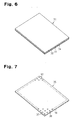
- a seat cover 31 as in Fig. 6 having three layers, for example, is used as a seat cover for covering a seat of a vehicle. More specifically, the seat cover 31 includes a fibrous sheet 32, a cushion sheet 33 bonded with the backside of the fibrous sheet 32, and a back lining 34 bonded with the backside of the cushion sheet 33.
- the fibrous sheet 32 is formed by, for example, a fabric or a vinyl chloride sheet.
- the cushion sheet 33 is formed of, for example, soft urethane foam.
- the back lining 34 is formed of, for example tricot or unwoven fabric. The back lining 34 improves the smoothness of the backside of the cushion sheet 33, thus making it easy to sew the seat cover 31 and install the seat cover 31 in the cushion body of the seat of the vehicle.
- the back lining 34 is bonded with the entire backside of the cushion sheet 33 through, for example, frame laminating. This decreases the air permeability of the seat cover 31. Further, the fibrous sheet 32 and the cushion sheet 33 exhibit a different extension rate than the extension rate of the back lining 34. Thus, when the seat cover 31 is secured to the cushion body, wrinkles tend to be caused in the seat cover 31. Also, the frame laminating for bonding the back lining 34 with the backside of the cushion sheet 33 increases the steps for manufacturing the cushion sheet 33, complicating the manufacture of the cushion sheet 33. The cost for manufacturing the cushion sheet 33 is thus raised.
- Japanese Laid-Open Patent Publication No. 2000-107471 proposes a cushion sheet 35, which is shown in Fig. 7.
- the cushion sheet 35 includes an air-permeable sheet material 36.
- a plurality of adhesive layers 38, or dots of adhesive, are formed on the backside of the air-permeable sheet material 36.
- the adhesive layers 38 are provided by applying hot-melt adhesives 37 on the backside of the air-permeable sheet material 36 in accordance with a dotted pattern. More specifically, the hot-melt adhesives 37 are extruded through a T die in a molten state and applied on the backside of the air-permeable sheet material 36 in such a manner as to form a prescribed pattern. This provides the adhesive layers 38 that are arranged in accordance with the dotted pattern. This ensures the air permeability of the cushion sheet 35 and the smoothness of the cushion sheet 35 that is comparable with that of the back lining 34 of the seat cover 31 of Fig. 6.
- the adhesive layers 38 must be arranged in accordance with the prescribed dotted pattern.
- the speed for applying the hot-melt adhesives 37 is thus restricted to a certain level. If such speed is excessively increased, the dots cannot be arranged in a desired manner. This makes it impossible to ensure a necessary smoothness of the cushion sheet 35, hampering sewing of the seat cover 31.
- a cushion sheet having a sheet body and a low-friction layer formed on the sheet body.
- the low-friction layer is formed by a plurality of synthetic resin fibers.
- the synthetic resin fibers are bonded with a surface of the sheet body in a state resembling a spread cloth.
- the present invention also provides a method for manufacturing a cushion sheet having a sheet body and a low-friction layer formed on the sheet body.
- the low-friction layer is formed by a plurality of synthetic resin fibers, and the synthetic resin fibers are bonded with a surface of the sheet body in a state resembling a spread cloth.
- the method includes: preparing the sheet body and a molten synthetic resin material for the fibers; and forming the low-friction layer by bonding the molten synthetic resin material with the surface of the sheet body such that the synthetic resin fibers in a state resembling a spread cloth are formed on the surface of the sheet body.
- a cushion sheet 11 has a sheet body 12 (for example, a product of INOAC CORPORATION, product number: EL-67F, thickness: 1.5 to 4 millimeters) and a low-friction layer 14.
- the low-friction layer 14 is formed on a side surface of the sheet body 12.
- the sheet body 12 is formed of a porous material and has a predetermined thickness.
- the porous material may be flexible polyurethane foam.
- the low-friction layer 14 has a friction coefficient lower than that of a conventional similar layer.
- the low-friction layer 14 is formed by bonding a plurality of synthetic resin fibers 13 with the side surface of the sheet body 12 in a non-uniform and continuously extended and curved manner.
- the synthetic resin fibers 13 are arranged on the sheet body 12 with clearances between adjacent ones of the synthetic resin fibers 13 and in a state resembling a spread cloth. Accordingly, the surface of the sheet body 12 is exposed between the synthetic resin fibers 13.
- the synthetic resin fibers 13 are formed of a resin that hardens through reaction with moisture in the air, which is a moisture curing resin.
- the moisture curing resin may be a polyurethane hot-melt moisture curing resin (which is, for example, a polyurethane hot-melt moisture curing resin: diphenyl methane diisocyanate of HITACHI KASEI POLYMER CO., LTD., type MDI, product number: YR067).
- each synthetic resin fiber 13 is preferably 10 to 600 micrometers, more preferably 13 to 400 micrometers, and further preferably 15 to 400 micrometers. If the diameter of each synthetic resin fiber 13 is less than 10 micrometers, the thickness of the low-friction layer 14 becomes insufficient. This decreases the surface smoothness of the cushion sheet 11. If the diameter of each synthetic resin fiber 13 is greater than 600 micrometers, the thickness of the low-friction layer 14 becomes excessively great or the amount of the material of the synthetic resin fibers 13 permeating through the sheet body 12 increases. This degrades the feel of the cushion sheet 11 and decreases the air permeability of the cushion sheet 11.
- the amount of the synthetic resin fibers 13 bonded with the surface of the sheet body 12 per square meter of the sheet body 12 is preferably 5 to 100 grams and more preferably 10 to 40 grams. If such amount is less than 5 grams, the density of the low-friction layer 14 becomes insufficient and the surface smoothness of the cushion sheet 11 is thus decreased. If the amount exceeds 100 grams, the density of the low-friction layer 14 becomes excessively high, thus decreasing the air permeability of the cushion sheet 11.
- the apparatus includes a pair of spinneret plates 17, 18 that are bonded with a lower surface of a support plate 16 and spaced at a predetermined distance.
- the spinneret plates 17, 18 have mutually opposing ends each defining a spinneret 19.
- the spinneret plate 17 includes an air inlet chamber 21 and the spinneret plate 18 includes an air inlet chamber 22.
- Each of the air inlet chambers 21, 22 is defined in a surface of the associated one of the spinneret plate 17, 18 that opposes the other spinneret plate 17, 18.
- the spinneret plate 17 also includes a resin supply chamber 20 defined in the surface of the spinneret plate 17 that opposes the spinneret plate 18.
- a plurality of resin introduction holes 23 extend through the support plate 16 and the spinneret plate 18 and thus communicate with the resin supply chamber 20.
- a plurality of air introduction holes 24 extend through the support plate 16 and the spinneret plate 17 and thus communicate with the air inlet chamber 21.
- a plurality of air introduction holes 25 extend through the support plate 16 and the spinneret plate 18 and thus communicate with the air inlet chamber 22.
- a nozzle plate 26 is arranged between the spinnerets 19.
- Each of the nozzle holes 27 corresponds to the resin supply chamber 20 and the air inlet chambers 21, 22.
- the lateral dimension of each nozzle hole 27 is, for example, approximately 0.4 millimeters.
- the sheet body 12 is arranged at a position spaced from the spinnerets 19 by a predetermined distance as shown in Figs. 3 and 4.
- the sheet body 12 is then moved in a direction perpendicular to the direction in which the nozzle holes 27 are arranged.
- molten synthetic resin material is supplied to the resin introduction holes 23 via a non-illustrated path.
- the material is then introduced into the resin supply chamber 20 through the resin introduction holes 23. The material is thus extruded from the nozzle holes 27 onto the opposing surface of the sheet body 12.
- the air that has been introduced into the air inlet chambers 21, 22 through the associated air introduction holes 24, 25 is ejected onto the surface of the sheet body 12 through the nozzle holes 27 together with the molten synthetic resin material.
- the synthetic resin material is extended in an elongated shape corresponding to fibers having a predetermined diameter, thus forming the synthetic resin fibers 13.
- the synthetic resin fibers 13 swing randomly. This causes the synthetic resin fibers 13 to be bonded with the surface of the sheet body 12 in a non-uniform and continuously extended and curved manner and in a state resembling a spread cloth.
- the synthetic resin fibers 13 then harden and thus provide the low-friction layer 14 on the surface of the sheet body 12.
- the synthetic resin fibers 13 are provided on the sheet body 12 in a non-uniform manner. Therefore, if the sheet body 12 is moved quickly and the machining speed is increased, undesired arrangement of the synthetic resin fibers 13 can be suppressed, unlike the prior art, by correspondingly increasing the speed for extruding the synthetic resin fibers 13.
- the synthetic resin fibers 13 are formed of the moisture curing resin and the spinnerets 19 of the manufacturing apparatus are spaced from the sheet body 12.
- the synthetic resin fibers 13 are bonded with the sheet body 12 in a semi-cured state. This suppresses permeation of the material of the synthetic resin fibers 13 through the sheet body 12.
- the surface of the sheet body 12 opposed to the surface corresponding to the low-friction layer 14 is covered by a fibrous sheet formed by, for example, a fabric or vinyl polychloride sheet.
- the fibrous sheet may be bonded with the surface of the sheet body 12 by adhesive. Although such bonding may generate heat, reactivation (re-melting) of the material of the synthetic resin fibers 13 is suppressed since the synthetic resin fibers 13 are formed of the moisture curing resin.
- the low-friction layer 14 formed of fibrous synthetic resin on the surface of the cushion sheet 11, the surface smoothness of the cushion sheet 11 is improved.
- the cushion sheet 11 can be handled efficiently, for example, after sewing of the cushion sheet 11 is completed.
- the cushion sheet 11 thus can be used comfortably for covering a vehicle seat.
- the low-friction layer 14 formed on the sheet body 12 makes it unnecessary to provide a back lining unlike the prior art. This decreases the quantity of components of the cushion sheet 11. Also, unlike the back lining of the prior art, the low-friction layer 14 substantially maintains elasticity of the sheet body 12. This suppresses generation of wrinkles on the sheet body 12 and on an exposed surface of the seat cover located above the sheet body 12.
- the low-friction layer 14 is formed on the surface of the sheet body 12 by providing the synthetic resin fibers 13.
- the synthetic resin fibers 13 are bonded with the surface of the sheet body 12 in the non-uniform manner and in a state resembling a spread cloth. This increases the manufacturing speed and thus improves productivity unlike the prior art in which the dot-like adhesive layers are arranged on the surface of the air-permeable sheet material in accordance with the predetermined pattern.
- the manufacturing apparatus may be deployed in a slicing step of the sheet body 12 in which the sheet body 12 is sliced to a predetermined thickness. In this manner, such slicing and formation of the low-friction layer 14 can be performed successively. This greatly improves the productivity and suppresses enlargement of the production facility.
- the molten synthetic resin material is extruded together with the air flow through the nozzle holes 27, which are spaced from the sheet body 12.
- the synthetic resin fibers 13 are thus bonded with the entire surface of the sheet body 12 in a state resembling a spread cloth. In this manner, the synthetic resin fibers 13 are provided uniformly on the entire surface of the sheet body 12 with increased efficiency.
- the ratio of the surface area relative to the volume of the material is increased.
- the synthetic resin fibers 13 are thus deployed on the surface of the sheet body 12 in a semi-cured state. This substantially prevents the material of the synthetic resin fibers 13 from penetrating through the sheet body 12. The amount of the material for forming the synthetic resin fibers 13 is thus reduced.
- the feel and the air permeability of the cushion sheet 11 are also maintained by suppressing penetration of the material of the synthetic resin fibers 13 through the sheet body 12. Accordingly, the cushion sheet 11 has improved feel, enhanced air permeability, and increased smoothness.
- the illustrated embodiment has the following advantages.
- the sewing efficiency of the sheet body 12 is increased.
- the air permeability and the feel of the cushion sheet 11 are also improved reliably.
- the cushion sheet 11 of the illustrated embodiment is formed quickly. This increases productivity for the cushion sheet 11 and thus lowers the cost for manufacturing the cushion sheet 11.
- the material of the synthetic resin fibers 13 are substantially prevented from penetrating through the sheet body 12. This reduces the amount of the material for forming the synthetic resin fibers 13 and thus the cost for manufacturing the cushion sheet 11. Further, the cushion sheet 11 with improved feel, enhanced air permeability, and increased smoothness is provided.
- the sheet body 12 is formed of the porous material. Since the porous material has improved feel and increased air permeability, the feel and the air permeability of the cushion sheet 11 are improved.
- each synthetic resin fiber 13 is set in the above-described range. This suppresses the penetration of the material of the synthetic resin fibers 13 through the sheet body 12. The synthetic resin fibers 13 are thus reliably provided on the surface of the sheet body 12 in a state resembling a spread cloth.
- the amount of the material of the synthetic resin fibers 13 bonded with the sheet body 12 is set in the above-described range. This increases the smoothness of the cushion sheet 11 while ensuring the increased air permeability of the cushion sheet 11.
- the synthetic resin fibers 13 are provided on the sheet body 12, and are extended and curved in a non-uniform manner. This makes it significantly easy to form the low-friction layer 14.
- the synthetic resin fibers 13 swing. This causes the synthetic resin fibers 13 to be bonded with the surface of the sheet body 12, and extended and curved in the non-uniform manner.
- each of the synthetic resin fibers 13 is disposed on the sheet body 12 as a continuous body.
- the synthetic resin fibers 13 may be provided on the sheet body 12, while being separated in sections each having a predetermined length.
- the synthetic resin fibers 13 may be bonded with the sheet body 12 in accordance with a uniform pattern.
- the synthetic resin fibers 13 may be provided in a grid-like or striped or spiral shape. In this case, regardless of the moving speed of the sheet body 12, the synthetic resin fibers 13 are reliably formed on the sheet body 12 by increasing the supply amount of the material for forming the synthetic resin fibers 13.
- the synthetic resin fibers 13 may be formed through spraying. More specifically, the molten synthetic resin material for forming the synthetic resin fibers 13 may be sprayed onto the surface of the sheet body 12. In this manner, multiple synthetic resin fibers 13 each having a decreased length are applied on the surface of the sheet body 12.
- the synthetic resin fibers 13 may be formed of a thermosetting resin.
- the material of the synthetic resin fibers 13 is supplied to the surface of the sheet body 12 in a heated atmosphere.
- the synthetic resin fibers 13 are thus cured by the heat.
- the synthetic resin fibers 13 may be formed of an ultraviolet curing resin. In this case, it is preferred that an ultraviolet radiation device be arranged with respect to the material of the synthetic resin fibers 13, which is provided through the nozzle holes 27.
- the cushion sheet 11 may be used for different purposes other than the seat cover for the vehicle seat. That is, the cushion sheet 11 may be used in protection casings for accommodating precision devices such as cameras and microscopes.
- the synthetic resin fibers 13 may be formed of a non-reactive thermoplastic resin that does not react to moisture (for example, product number #9618 of HITACHI KASEI POLYMER CO., LTD.). This makes it unnecessary to perform complicated work for maintaining the manufacturing facility, such as blockage of the air when ending the operation of the facility and replacement of a washing agent before a long-term stand-by period.
- a non-reactive thermoplastic resin that does not react to moisture
- the cushion sheet 11 was manufactured in the following manner. More specifically, the sheet body 12 was formed by cutting a urethane foam sheet with a thickness of 2.5 millimeters (product number EL-67F) of INOAC CORPORATION in accordance with the length of 1,300 millimeters and the width of 320 millimeters. The sheet body 12 was then mounted on a transport roller conveyor that operated at the speed of 30 meters per minute. Meanwhile, the manufacturing apparatus of the illustrated embodiment was actuated. The polyurethane hot-melt moisture curing resin (diphenyl methane diisocyanate, MDI type, product number: YR067) of HITACHI KASEI POLYMER CO., LTD.
- the polyurethane hot-melt moisture curing resin diphenyl methane diisocyanate, MDI type, product number: YR067) of HITACHI KASEI POLYMER CO., LTD.
- the cushion sheet of comparative example 1 had a sheet body identical to those of examples 1 to 4.
- the polyurethane hot-melt moisture curing resin was product number YR067 of HITACHI KASEI POLYMER CO., LTD. and was applied on a surface of the sheet body in accordance with a coating weight of 10 g/m 2 using a coating coat applicator (product number: BC62) of NORDSON KK.
- Coating coat refers to a technique in which hot-melt adhesive is pressed against a target by a T die. In the coating coat, for example, the distance between the distal end of the T die and the target, the viscosity of the resin, or the displacement were controlled. In this manner, the pattern for applying the viscous hot-melt resin was modified from a linear shape to a broken-line-like shape, thus forming a low-friction layer.
- the cushion sheet of comparative example 2 had a sheet body identical to those of examples 1 to 4.
- a tricot knit formed of nylon product of KABUSHIKI KAISHA KIRYU TRICOT, product number: 15d was bonded with a surface of the sheet body as a back lining.
- Examples 1 to 4 and comparative examples 1, 2 were mounted on base materials 1 to 4.
- the base materials 1 to 4 were formed as follows.
- Table 1 shows the obtained measurements.
- the coating weight for each of examples 1 to 4 represents the application amount of the synthetic resin fibers 13.
- a coating weight 10 corresponds to 10g/cm 2 .
- examples 1 to 4 showed lower static and dynamic friction coefficients than comparative examples 1, 2. That is, examples 1 to 4 exhibited improved smoothness compared to comparative examples 1, 2.
- examples 1 and 2 the minimum value, the average value, and the maximum value of the synthetic resin fibers 13 are all in a range of 15 to 400 micrometers. Therefore, examples 1 and 2 exhibit a comparable level of smoothness as that of examples 3 and 4 while using a less amount of synthetic resin material than examples 3 and 4, in which the maximum value of the diameters of the synthetic resin fibers 13 exceeded 400 micrometers. Thus, examples 1 and 2 reduce the manufacture costs compared to examples 3 and 4, and facilitate the bonding process with synthetic resin.
Landscapes
- Engineering & Computer Science (AREA)
- Aviation & Aerospace Engineering (AREA)
- Transportation (AREA)
- Mechanical Engineering (AREA)
- Laminated Bodies (AREA)
Applications Claiming Priority (1)
| Application Number | Priority Date | Filing Date | Title |
|---|---|---|---|
| JP2005045957 | 2005-02-22 |
Publications (3)
| Publication Number | Publication Date |
|---|---|
| EP1693189A2 true EP1693189A2 (de) | 2006-08-23 |
| EP1693189A3 EP1693189A3 (de) | 2008-06-25 |
| EP1693189B1 EP1693189B1 (de) | 2010-04-21 |
Family
ID=36643409
Family Applications (1)
| Application Number | Title | Priority Date | Filing Date |
|---|---|---|---|
| EP20060003146 Expired - Fee Related EP1693189B1 (de) | 2005-02-22 | 2006-02-16 | Polsterfolie und Herstellungsverfahren für eine Polsterfolie |
Country Status (4)
| Country | Link |
|---|---|
| US (1) | US7431982B2 (de) |
| EP (1) | EP1693189B1 (de) |
| CN (1) | CN1824601B (de) |
| DE (1) | DE602006013726D1 (de) |
Cited By (1)
| Publication number | Priority date | Publication date | Assignee | Title |
|---|---|---|---|---|
| EP2296937A1 (de) * | 2008-06-24 | 2011-03-23 | C.R.F. Società Consortile per Azioni | Stützkörper für einen fahrzeugsitz |
Families Citing this family (1)
| Publication number | Priority date | Publication date | Assignee | Title |
|---|---|---|---|---|
| CN106455835A (zh) * | 2014-04-16 | 2017-02-22 | 帝人株式会社 | 被罩 |
Citations (4)
| Publication number | Priority date | Publication date | Assignee | Title |
|---|---|---|---|---|
| US3654063A (en) * | 1970-04-09 | 1972-04-04 | Monsanto Co | Carpet underpad composite |
| US5750246A (en) * | 1995-03-10 | 1998-05-12 | Kurashiki Boseki Kabushiki Kaisha | Facing for seat |
| US20020155255A1 (en) * | 1999-08-09 | 2002-10-24 | Tsunenori Oguri | Skin material, skinned cushion, and process for producing skinned cushion |
| WO2003033253A1 (en) * | 2001-10-12 | 2003-04-24 | Viktor Achter Limited | Composite foam backed fabric |
Family Cites Families (5)
| Publication number | Priority date | Publication date | Assignee | Title |
|---|---|---|---|---|
| US5294258A (en) * | 1992-04-08 | 1994-03-15 | Nordson Corporation | Apparatus for producing an integral adhesive matrix |
| JP3502407B2 (ja) * | 1992-12-21 | 2004-03-02 | 株式会社イノアックコーポレーション | クッション材及びその製造方法 |
| DE4329890A1 (de) * | 1993-09-06 | 1995-03-09 | Ruetgerswerke Ag | Verbundwerkstoffe, Verfahren und Bindemittel zu ihrer Herstellung |
| JP2000045957A (ja) | 1998-07-24 | 2000-02-15 | Hitachi Koki Co Ltd | 圧縮機のアンロード制御装置 |
| JP4540148B2 (ja) * | 1998-08-07 | 2010-09-08 | 株式会社イノアックコーポレーション | 表皮材付きクッションの製造方法 |
-
2006
- 2006-02-14 US US11/353,751 patent/US7431982B2/en not_active Expired - Fee Related
- 2006-02-16 EP EP20060003146 patent/EP1693189B1/de not_active Expired - Fee Related
- 2006-02-16 DE DE200660013726 patent/DE602006013726D1/de active Active
- 2006-02-21 CN CN2006100083936A patent/CN1824601B/zh not_active Expired - Fee Related
Patent Citations (4)
| Publication number | Priority date | Publication date | Assignee | Title |
|---|---|---|---|---|
| US3654063A (en) * | 1970-04-09 | 1972-04-04 | Monsanto Co | Carpet underpad composite |
| US5750246A (en) * | 1995-03-10 | 1998-05-12 | Kurashiki Boseki Kabushiki Kaisha | Facing for seat |
| US20020155255A1 (en) * | 1999-08-09 | 2002-10-24 | Tsunenori Oguri | Skin material, skinned cushion, and process for producing skinned cushion |
| WO2003033253A1 (en) * | 2001-10-12 | 2003-04-24 | Viktor Achter Limited | Composite foam backed fabric |
Cited By (3)
| Publication number | Priority date | Publication date | Assignee | Title |
|---|---|---|---|---|
| EP2296937A1 (de) * | 2008-06-24 | 2011-03-23 | C.R.F. Società Consortile per Azioni | Stützkörper für einen fahrzeugsitz |
| EP2138348B1 (de) * | 2008-06-24 | 2013-05-01 | C.R.F. Società Consortile per Azioni | Stützkörper für einen Fahrzeugsitz. |
| US8491057B2 (en) | 2008-06-24 | 2013-07-23 | C.R.F. SOCIETá CONSORTILE PER AZIONI | Support body of a seat for vehicles |
Also Published As
| Publication number | Publication date |
|---|---|
| DE602006013726D1 (de) | 2010-06-02 |
| EP1693189B1 (de) | 2010-04-21 |
| CN1824601B (zh) | 2011-11-09 |
| US7431982B2 (en) | 2008-10-07 |
| EP1693189A3 (de) | 2008-06-25 |
| CN1824601A (zh) | 2006-08-30 |
| US20060189242A1 (en) | 2006-08-24 |
Similar Documents
| Publication | Publication Date | Title |
|---|---|---|
| CN108025544B (zh) | 制造地板的方法和用于形成地面覆盖物的地板 | |
| JP4570965B2 (ja) | ベルトならびにバルクティッシュ及びタオルと不織製品及び不織布製造に使用するベルトを生成する方法 | |
| US4812186A (en) | Process for the manufacture of cellular core laminated elements | |
| KR100294564B1 (ko) | 통기성다층직물적층제품및적층장치 | |
| US6364976B2 (en) | Method of manufacturing laminated structures with multiple denier polyester core fibers, randomly oriented reinforcement fibers | |
| CN101801634B (zh) | 用于制造泡沫制品的方法 | |
| JP2014502920A (ja) | カバー層に液体反応混合物を塗布するための方法と装置 | |
| US5759927A (en) | Glass-fiber-containing non-woven polymer web, and process for preparing same | |
| WO2006117868A1 (ja) | 繊維複合材とその製造方法 | |
| US20020155255A1 (en) | Skin material, skinned cushion, and process for producing skinned cushion | |
| EP1693189B1 (de) | Polsterfolie und Herstellungsverfahren für eine Polsterfolie | |
| CA2480689A1 (en) | Arrangement and methods for the manufacture of composite layer structures | |
| WO2020091175A1 (ko) | 감성품질 향상을 위한 자동차 시트용 원단 합포방법 | |
| KR101643186B1 (ko) | 트림용 복합재 포일 및 그의 제조방법 | |
| EP0884160B1 (de) | Verfahren zur herstellung eines dreidimensional geformten teppichs für kraftfahrzeuge | |
| JP2000107471A (ja) | 表皮材と表皮材付きクッションと表皮材付きクッションの製造方法 | |
| JP4120236B2 (ja) | 内装材及び内装材の製造方法 | |
| JP6416044B2 (ja) | 床材の製造方法及び床材 | |
| JP5005231B2 (ja) | クッションシート及びその製造方法 | |
| KR101741190B1 (ko) | 무광 점착테이프 제조 장치 및 방법 | |
| JP2799182B2 (ja) | クッション材の製造方法 | |
| JP2000313081A (ja) | ウレタン発泡成形用補強材 | |
| JP3663011B2 (ja) | 長繊維補強ポリウレタン発泡成形体の製造方法 | |
| JP4301110B2 (ja) | 繊維補強樹脂成形品の連続成形方法及び装置 | |
| JP2022160341A (ja) | 車両用フロアスペーサ、及び車両用フロアスペーサの製造方法 |
Legal Events
| Date | Code | Title | Description |
|---|---|---|---|
| PUAI | Public reference made under article 153(3) epc to a published international application that has entered the european phase |
Free format text: ORIGINAL CODE: 0009012 |
|
| AK | Designated contracting states |
Kind code of ref document: A2 Designated state(s): AT BE BG CH CY CZ DE DK EE ES FI FR GB GR HU IE IS IT LI LT LU LV MC NL PL PT RO SE SI SK TR |
|
| AX | Request for extension of the european patent |
Extension state: AL BA HR MK YU |
|
| PUAL | Search report despatched |
Free format text: ORIGINAL CODE: 0009013 |
|
| AK | Designated contracting states |
Kind code of ref document: A3 Designated state(s): AT BE BG CH CY CZ DE DK EE ES FI FR GB GR HU IE IS IT LI LT LU LV MC NL PL PT RO SE SI SK TR |
|
| AX | Request for extension of the european patent |
Extension state: AL BA HR MK YU |
|
| RIC1 | Information provided on ipc code assigned before grant |
Ipc: D04H 13/00 20060101ALN20080522BHEP Ipc: B05D 5/08 20060101ALN20080522BHEP Ipc: B32B 5/18 20060101ALN20080522BHEP Ipc: B32B 5/24 20060101ALI20080522BHEP Ipc: B32B 27/02 20060101ALN20080522BHEP Ipc: C08J 9/36 20060101ALN20080522BHEP Ipc: B60N 2/58 20060101AFI20080522BHEP |
|
| 17P | Request for examination filed |
Effective date: 20081223 |
|
| AKX | Designation fees paid |
Designated state(s): DE FR GB |
|
| GRAP | Despatch of communication of intention to grant a patent |
Free format text: ORIGINAL CODE: EPIDOSNIGR1 |
|
| GRAS | Grant fee paid |
Free format text: ORIGINAL CODE: EPIDOSNIGR3 |
|
| GRAA | (expected) grant |
Free format text: ORIGINAL CODE: 0009210 |
|
| AK | Designated contracting states |
Kind code of ref document: B1 Designated state(s): DE FR GB |
|
| REG | Reference to a national code |
Ref country code: GB Ref legal event code: FG4D |
|
| REF | Corresponds to: |
Ref document number: 602006013726 Country of ref document: DE Date of ref document: 20100602 Kind code of ref document: P |
|
| PLBE | No opposition filed within time limit |
Free format text: ORIGINAL CODE: 0009261 |
|
| STAA | Information on the status of an ep patent application or granted ep patent |
Free format text: STATUS: NO OPPOSITION FILED WITHIN TIME LIMIT |
|
| 26N | No opposition filed |
Effective date: 20110124 |
|
| REG | Reference to a national code |
Ref country code: FR Ref legal event code: PLFP Year of fee payment: 11 |
|
| REG | Reference to a national code |
Ref country code: FR Ref legal event code: PLFP Year of fee payment: 12 |
|
| REG | Reference to a national code |
Ref country code: FR Ref legal event code: PLFP Year of fee payment: 13 |
|
| PGFP | Annual fee paid to national office [announced via postgrant information from national office to epo] |
Ref country code: DE Payment date: 20190205 Year of fee payment: 14 Ref country code: GB Payment date: 20190213 Year of fee payment: 14 Ref country code: FR Payment date: 20190111 Year of fee payment: 14 |
|
| REG | Reference to a national code |
Ref country code: DE Ref legal event code: R119 Ref document number: 602006013726 Country of ref document: DE |
|
| GBPC | Gb: european patent ceased through non-payment of renewal fee |
Effective date: 20200216 |
|
| PG25 | Lapsed in a contracting state [announced via postgrant information from national office to epo] |
Ref country code: GB Free format text: LAPSE BECAUSE OF NON-PAYMENT OF DUE FEES Effective date: 20200216 Ref country code: DE Free format text: LAPSE BECAUSE OF NON-PAYMENT OF DUE FEES Effective date: 20200901 Ref country code: FR Free format text: LAPSE BECAUSE OF NON-PAYMENT OF DUE FEES Effective date: 20200229 |