EP1691890B1 - Multiple room radiation treatment system - Google Patents
Multiple room radiation treatment system Download PDFInfo
- Publication number
- EP1691890B1 EP1691890B1 EP04800421A EP04800421A EP1691890B1 EP 1691890 B1 EP1691890 B1 EP 1691890B1 EP 04800421 A EP04800421 A EP 04800421A EP 04800421 A EP04800421 A EP 04800421A EP 1691890 B1 EP1691890 B1 EP 1691890B1
- Authority
- EP
- European Patent Office
- Prior art keywords
- radiation
- treatment
- gantry
- head
- treatment room
- Prior art date
- Legal status (The legal status is an assumption and is not a legal conclusion. Google has not performed a legal analysis and makes no representation as to the accuracy of the status listed.)
- Not-in-force
Links
Images


Classifications
-
- A—HUMAN NECESSITIES
- A61—MEDICAL OR VETERINARY SCIENCE; HYGIENE
- A61B—DIAGNOSIS; SURGERY; IDENTIFICATION
- A61B6/00—Apparatus for radiation diagnosis, e.g. combined with radiation therapy equipment
-
- A—HUMAN NECESSITIES
- A61—MEDICAL OR VETERINARY SCIENCE; HYGIENE
- A61N—ELECTROTHERAPY; MAGNETOTHERAPY; RADIATION THERAPY; ULTRASOUND THERAPY
- A61N5/00—Radiation therapy
- A61N5/10—X-ray therapy; Gamma-ray therapy; Particle-irradiation therapy
- A61N5/1077—Beam delivery systems
- A61N5/1079—Sharing a beam by multiple treatment stations
-
- A—HUMAN NECESSITIES
- A61—MEDICAL OR VETERINARY SCIENCE; HYGIENE
- A61B—DIAGNOSIS; SURGERY; IDENTIFICATION
- A61B6/00—Apparatus for radiation diagnosis, e.g. combined with radiation therapy equipment
- A61B6/44—Constructional features of apparatus for radiation diagnosis
- A61B6/4429—Constructional features of apparatus for radiation diagnosis related to the mounting of source units and detector units
-
- A—HUMAN NECESSITIES
- A61—MEDICAL OR VETERINARY SCIENCE; HYGIENE
- A61N—ELECTROTHERAPY; MAGNETOTHERAPY; RADIATION THERAPY; ULTRASOUND THERAPY
- A61N5/00—Radiation therapy
- A61N5/10—X-ray therapy; Gamma-ray therapy; Particle-irradiation therapy
-
- A—HUMAN NECESSITIES
- A61—MEDICAL OR VETERINARY SCIENCE; HYGIENE
- A61N—ELECTROTHERAPY; MAGNETOTHERAPY; RADIATION THERAPY; ULTRASOUND THERAPY
- A61N5/00—Radiation therapy
- A61N5/10—X-ray therapy; Gamma-ray therapy; Particle-irradiation therapy
- A61N5/1077—Beam delivery systems
- A61N5/1081—Rotating beam systems with a specific mechanical construction, e.g. gantries
-
- A—HUMAN NECESSITIES
- A61—MEDICAL OR VETERINARY SCIENCE; HYGIENE
- A61B—DIAGNOSIS; SURGERY; IDENTIFICATION
- A61B6/00—Apparatus for radiation diagnosis, e.g. combined with radiation therapy equipment
- A61B6/40—Apparatus for radiation diagnosis, e.g. combined with radiation therapy equipment with arrangements for generating radiation specially adapted for radiation diagnosis
- A61B6/4064—Apparatus for radiation diagnosis, e.g. combined with radiation therapy equipment with arrangements for generating radiation specially adapted for radiation diagnosis specially adapted for producing a particular type of beam
- A61B6/4092—Apparatus for radiation diagnosis, e.g. combined with radiation therapy equipment with arrangements for generating radiation specially adapted for radiation diagnosis specially adapted for producing a particular type of beam for producing synchrotron radiation
-
- Y—GENERAL TAGGING OF NEW TECHNOLOGICAL DEVELOPMENTS; GENERAL TAGGING OF CROSS-SECTIONAL TECHNOLOGIES SPANNING OVER SEVERAL SECTIONS OF THE IPC; TECHNICAL SUBJECTS COVERED BY FORMER USPC CROSS-REFERENCE ART COLLECTIONS [XRACs] AND DIGESTS
- Y10—TECHNICAL SUBJECTS COVERED BY FORMER USPC
- Y10S—TECHNICAL SUBJECTS COVERED BY FORMER USPC CROSS-REFERENCE ART COLLECTIONS [XRACs] AND DIGESTS
- Y10S128/00—Surgery
- Y10S128/92—Computer assisted medical diagnostics
-
- Y—GENERAL TAGGING OF NEW TECHNOLOGICAL DEVELOPMENTS; GENERAL TAGGING OF CROSS-SECTIONAL TECHNOLOGIES SPANNING OVER SEVERAL SECTIONS OF THE IPC; TECHNICAL SUBJECTS COVERED BY FORMER USPC CROSS-REFERENCE ART COLLECTIONS [XRACs] AND DIGESTS
- Y10—TECHNICAL SUBJECTS COVERED BY FORMER USPC
- Y10S—TECHNICAL SUBJECTS COVERED BY FORMER USPC CROSS-REFERENCE ART COLLECTIONS [XRACs] AND DIGESTS
- Y10S378/00—X-ray or gamma ray systems or devices
- Y10S378/901—Computer tomography program or processor
Definitions
- the present invention generally refers to an irradiation system, and in particular to such a system being able to direct a radiation beam into multiple treatment rooms.
- a common general method is to position the patient on a couch.
- a radiation head and gantry are directing a diagnostic or therapeutic beam onto the patient in order to deliver radiation to a certain target or treatment volume, e.g. a tumor.
- a typical radiation machine according to the prior art is schematically illustrated in Fig. 1.
- the radiation machine comprises an isocentric gantry 80 designed in a general L shape and a rotational support provided at one axial end of the body of the machine for supporting the gantry 80.
- the gantry 80 can rotate around a rotation axis 30 relative the support in order to deliver a radiation beam, schematically illustrated by 10, from a radiation head 20 into a target volume 55 of a patient 50 positioned on a patient couch 40.
- the tissue or target volume 55 to be radiated is preferably positioned around a so-called isocenter typically formed by the intersection of three axes at a common point. These axes include the gantry rotation axis 30, the central axis of the radiation beam 10, the major rotational axis 45 of the treatment couch 40, which is also the rotation axis of the collimator head 20 in the figure.
- a problem with such prior art radiation therapy machines is their limited capacity in terms of the total number of patients that can be treated in a given time interval.
- the actual irradiation is rather quick, i.e. it typically lasts a few minutes (1- 2.5 minutes), a much longer treatment set-up normally precedes the irradiation.
- the personnel positions the patient to be treated as accurately as possible, typically based on a treatment plan, which has been developed or compiled earlier based on diagnostic data, radiation beam data, etc.
- a treatment set-up is typically performed to test and verify the beam directions and the treatment plan.
- the primary aim is setting up the equipment and patient according to the treatment plan.
- portal images i.e. images based on the treatment beam itself, are used to verify the treatment and monitor its reproducibility.
- in vivo dosimetry or related techniques may be used to check the delivered radiation dose in the target volume and/or in adjacent tissues, particularly in organs at risk. If the measured data corresponds to the planed position in the treatment plan, the actual radiation therapy treatment may be safely initiated.
- the total treatment takes considerably longer time, generally at least 5 - 10 minutes and often more, than the actual irradiation.
- the treatment set-up should be adjusted. This may in some cases simply be a correction of some set-up parameters but also larger adjustments requiring a renewed treatment planning process with new anatomical information from a renewed diagnostic procedure.
- a renewed treatment simulation may also be needed, increasing the time to treatment by a day or two.
- the time, during which a radiation machine actually is employed for irradiating a patient constitutes a small portion of the total time, during which the machine is occupied.
- This of course leads to poor utilization of the costly radiation machines and equipment and that fewer patients can be treated during a given period of time.
- This problem will be worsen further in cases where the patient undresses in the treatment room, the patient feels uncomfortable and wants to talk to the therapy assistants about various problems with the treatment, etc.
- the designs of the patient couches and the two machines used for the simulation and the treatment, respectively are similar, it may be more difficult to correctly simulate the treatment using a different machine and possibly a different couch top. This is due to problems with positioning the patient exactly in the same way on two different couches, even though the couches may have the same design.
- tissue and organs, including the target volume with a tumor are deformable elastic structures and their positions relative to reference points used in the treatment plan are not rigid, but may change depending on e.g. posture of the patient, filling degree of bladder, respiratory motion, etc. Therefore, although the reference points may be aligned correctly during the treatment relative those during the simulation, the target volume may be misaligned.
- a therapy system adapted for cancer treatment using light ion radiation beams includes an ion source providing light ions to an accelerator system including a synchrotron.
- An ion beam transport system guides an extracted high energy beam from the synchrotron into three different treatment rooms.
- a static gantry provides horizontal ion beam irradiation.
- a respective rotatable isocentric gantry is arranged.
- US-A-5 349 198 discloses a beam supply device comprising a rotatable deflection magnet, a rotatable beam transportation device and a plurality of beam utilization rooms disposed around the rotational axis of of the rotatable magnet.
- the present invention overcomes these and other drawbacks of the prior art arrangements.
- the present invention involves a radiation system or machine with an excentric gantry that can be used for irradiating subjects in multiple irradiation or treatment rooms as defined in claim 1.
- a gantry it is possible to irradiate, i.e. deliver radiation treatment doses, to a first subject in a first treatment room while simultaneously performing a treatment set-up and simulation procedure for at least a second subject in a second treatment room using the same radiation treatment gantry.
- the gantry can be turned for delivering radiation treatment doses to the second subject simultaneously as a treatment follow-up involving the first subject or a new treatment set-up involving a third subject is performed in the first treatment room.
- the capacity of the radiation system of the present invention in terms of the total number of subjects to be treated during a given period of time is much larger compared to machines of the prior art.
- more time is available for patient care in each treatment room both before and after each treatment occasion.
- the radiation system of the invention comprises a gantry adapted for arrangement in connection with multiple treatment rooms separated by radiation-shielding or -isolating separating members, e.g. radiation-shielding partitions (walls) and/or ceilings/floors.
- a radiation head is mechanically supported by the gantry and is movable relative the gantry between at least a first position for directing a radiation beam into the first treatment room and a second position for directing the radiation beam into the second treatment room.
- the gantry of the radiation system is preferably arranged in the intersection of the partitions and/or the ceiling/floor separating the multiple treatment rooms.
- the radiation system typically has a spherical or cylindrical design, allowing a radiation head to rotate in a dedicated spacing in the partitions and/or ceiling/floor.
- the radiation head delivering the radiation doses can be turned between the different treatment rooms and therefore irradiate subjects positioned in these different such rooms.
- the gantry could include a static gantry part attached to the separating members. In such a case, a movable gantry part is movably (rotatably) supported by the static gantry part. The radiation head is then preferably attached to this movable gantry part.
- each treatment room preferably comprises or has access to a simulator head with e.g. a light optical and/or diagnostic X-ray system, being able to simulate the therapeutic beam from the radiation head.
- a simulator head with e.g. a light optical and/or diagnostic X-ray system, being able to simulate the therapeutic beam from the radiation head.
- These simulator heads could be arranged and move concentrically on the gantry.
- the low cost radiation simulator could be used for patient set-up before the radiation head is turned into the treatment room for the real treatment.
- a few simulator heads could move between rooms and assist in setting up the patient prior to the treatment.
- the excentric gantry of the radiation system of the invention preferably comprises a beam scanning and bending system, such as a magnet-based system, adapted for scanning and bending an incident radiation beam onto a subject in form of a narrow pencil beam.
- This scanning and bending system, or at least a portion thereof, is then rotated as the radiation head and possibly gantry of the radiation system is turned between different rooms.
- a bending magnet of the bending system could be laminated to allow fast field changes between accelerator pulses but could also be super-conducting to minimize the bending radius of the magnet.
- the excentric gantry is well adapted for usage with light ions from protons and upwards to carbon and oxygen ions, including for example protons, deuterons, tritium and helium, lithium, beryllium, boron, carbon and oxygen ions.
- the present invention relates to a radiation system or machine with a so-called excentric gantry design that can be used for providing a radiation beam into multiple, i.e. at least two, irradiation or treatment rooms.
- the gantry is adapted for arrangement in connection with the multiple treatment rooms, which are separated by radiation-isolating or -shielding separating members.
- the gantry mechanically supports a radiation head. This radiation head is movable relative the gantry (and the separating members) between different positions for directing a radiation beam into the different treatment rooms.
- a gantry design it is possible to irradiate, e.g. to deliver radiation treatment doses to a first subject or patient, in a first treatment room while simultaneously allowing preparation for treatment (treatment set-up), simulation or performing treatment follow-up procedure for at least a second subject in another treatment room using the same radiation delivery system and gantry.
- the capacity of the radiation system of the invention in terms of the total number of patients to be treated for a given period of time, is much larger compared to the prior art machines, e.g. the radiation machines of Fig. 1.
- a radiation therapy system delivering irradiation doses to a patient for the purpose of treatment, and then primarily curative radiation therapy, i.e. to eradicate a tumor.
- This radiation therapy system could also be employed for palliative radiation therapy, where the aim is generally to improve quality of life of the patient by maintaining local tumor control, relieve a symptom or prevent or delay an impending symptom, and not necessarily to eradicate the tumor.
- the radiation system could alternatively be employed for other radiation purposes, such a single dose radiation therapy, radiation diagnostics or radiation processing.
- the radiation system could be used for combined radiation therapy and diagnosis.
- the radiation head can deliver both a (high-energy) radiation treatment beam and a (low-energy) radiation diagnostic beam.
- the radiation system according to the present invention can be applied for any radiation purposes, where it is desired to direct a radiation beam onto an object or patient in a treatment room simultaneously as a radiation simulation, set-up or follow-up is performed in a (neighboring) treatment room involving another object or patient, to be subsequently irradiated or already has been irradiated, using the same radiation gantry.
- Fig. 2 schematically illustrates a radiation system or machine 1 of the invention with an excentric gantry 100 that is able to irradiate subjects or patients 50-1 to 50-4 in four different treatment rooms 61 to 64.
- the radiation gantry is arranged in connection with these four treatment rooms 61 to 64.
- the gantry 100 is positioned in the intersection of the separating members, i.e. the walls or partitions 72, 74 and the ceiling/floor 71, 73, separating the four rooms 61 to 64.
- the treatment rooms 61 and 64 are positioned one floor beneath the treatment rooms 62 and 63.
- the separating members 71 to 74 separating the relevant treatment rooms 61 to 64 have radiation-shielding properties.
- the separating members 71 to 74 preferably prevent the treatment radiation beam 110 from leaking from the currently irradiated treatment room 61 to the other treatment rooms 62 to 64.
- the separating members 71 to 74 stop (absorb) the treatment radiation 110 so that the leaking radiation levels in the adjacent treatment rooms 62 to 64 are within defined safety margins.
- the choice of material and material thickness to use for the separating members 71 to 74 depend on properties of the employed treatment radiation 110, e.g. the energy level of the treatment beam 110, the type of radiation used, etc., and can be non-inventively determined by the person skilled in the art.
- Suitable materials for the separating members 71 to 74 include, but are not limited to, concrete, borated polyethylene and lead.
- the material surrounding and enclosing the radiation transport system, guiding the radiation into the radiation head 120 preferably has good radiation-shielding properties.
- the radiation gantry 100 typically has a spherical or cylindrical design, allowing a radiation head 120 to rotate in a dedicated spacing in the walls 72, 74 and ceiling/floor 71, 73.
- the gantry 100 is directed to irradiate 110 a target volume 55-1 in a first patient 50-1 positioned on a treatment couch 40-1 in a first treatment room 61.
- the radiation system 1 preferably also comprises a radiation shielding 150, preferably a rotary radiation shielding, and bending magnet (see Figs. 7-11) to deflect the radiation beam 110 into the currently used treatment room 61 and prevent it from reaching the other treatment rooms 62 to 64.
- the treatment rooms 61 to 64 preferably comprise or have access to simulator heads 200-2 to 220-4 with a light optical and/or X-ray system that is able to simulate the therapeutic beam 110.
- These simulator heads 200-2 to 200-4 could be arranged and move on a rail just outside of the shield 150.
- the low cost simulator 200-2 to 200-4 could be used for patient set-up before the radiation head 120 is turned into the treatment room for treatment operation. It is anticipated by the present invention that these simulator heads 200-2 to 200-4 instead, or alternatively, can be employed for treatment follow-up purposes.
- three patients 50-2 to 50-4 are positioned on a respective treatment couch 40-2 to 40-4 and are currently subject to a treatment set-up (follow-up) and simulation procedure using the simulator heads 200-2 to 200-4 and simulator beams 210-2 to 210-4.
- a stereotactic treatment couch 40-1 to 40-4 is preferably used in the treatment rooms 61 to 64. Such a couch 40-1 to 40-4 is then automatically positioned and individually adjusted to each patient 50-1 to 50-4.
- one and the same couch 40-1 to 40-4 can be used both for the patient set-up (and follow-up) procedure and the treatment and diagnostic imaging activities.
- the treatment rooms 61 to 64 are equipped with one simulator head 200-2 to 200-4 each.
- two or more rooms 61 and 62 could share a single common simulator 200-2.
- the simulator 200-2 is preferably able to move, e.g. by means of a rail system, in a dedicated gap 80 in the floor/ceiling 71 (or wall) separating the rooms 61 and 62.
- the gantry 100 may be turned so that the radiation head 120 now can deliver radiation doses to another patient 50-2 in another treatment rooms 62.
- This scenario is illustrated in Fig. 3, where the radiation head 120 (and possibly the gantry 100) has been rotated to irradiate a target volume 55-2 of a second patient 50-2.
- the simulator head 200-2 of the room 62 where the patient 50-2 currently is being irradiated using the treatment beam 110, is moved away either to one side of the room 62 in order to allow the radiation head 120 to irradiate the patient 50-2 or to the neighboring treatment room 61 for usage therein in treatment simulation.
- a new patient 50-1 may be positioned on the couch 40-1 and a set-up procedure and simulator using a simulator head 200-2 can be performed.
- a treatment follow-up and subsequently patient exit procedure can be performed involving the previously irradiated patient.
- the sequence of events taking place in a given treatment room is as follows. Firstly, the equipment (couch and radiation and positioning equipment) in the room is readjusted in order to prepare for a next patient to be treated. A patient set-up is then conducted where the patient is accurately positioned on a couch, preferably a stereotactic couch, using different patient positioning systems, e.g. laser-based positioning systems, such as a patient positioning system described in the international patent application WO 2004/000120 . Once the patient is accurately positioned on the (stereotactic) couch, a treatment simulation is then performed. During this simulation a light optical and/or diagnostic X-ray system in a simulator head of the radiation system of the invention is used. Thereafter the actual treatment can be performed.
- a light optical and/or diagnostic X-ray system in a simulator head of the radiation system of the invention is used. Thereafter the actual treatment can be performed.
- the treatment rooms 61 to 64 and patients 50-1 to 50-4 will generally have access to the therapeutic beam about every 10 minutes.
- this implies that up to (and sometimes, especially for simple treatment, more than) 6 x 4 24 patients can be treated per hour in a very busy therapy center, and still allowing ample set-up time and patient care in each treatment room 61 to 64.
- a single radiation gantry with a single beam transport and scanning system can be employed for both treatment radiation and treatment set-up and simulation in multiple treatment rooms.
- Figs. 2 and 3 Very many different room configurations can be anticipated from the basic four rooms configuration illustrated in Figs. 2 and 3. Depending on which quadrant a treatment room is located around the central excentric gantry, typically 30 - 60° oblique lateral anterior (room 61 and 64) or posterior (room 62 and 63) beam directions are possible. With light ions it is very convenient to treat a patient requiring 2-4 beam portal directions in his treatment plan by one beam portal per day and, thus, sequentially use the different treatment rooms of Figs. 2 and 3 as required by the beam directions. Thus, one and the same patient can, at different irradiation occasions, be irradiated in different treatment rooms, thereby receiving a treatment radiation beam from different incident angles and directions.
- FIG. 4 schematically illustrates this situation with four different treatment rooms 61 to 64 having access to one common radiation system 1 with excentric gantry design 100 according to the invention. Due to the position of the gantry 100 in the ceiling 71 relative a patient 50-1 on a couch 40-1 in room 61, straight vertical treatment beams 110 are possible. Similarly, for a patient 50-3 in the treatment room 63 posterior vertical beams are possible. However, in another treatment room 64 the beams will obliquely incident into a patient. In the figure, the patient support 40-4 of this room 64 is empty, schematically illustrating the principle with the patient entry/exit procedure.
- a patient 50-2 may be vertically irradiated. It is anticipated by the invention that an excentric gantry and radiation system of the present invention could be adapted for only radiating horizontally, only vertically, only obliquely or a combination of horizontally, vertically and/or obliquely.
- the simulator heads 200-1 to 200-3 have been arranged in dedicated hollows or portions of the gantry 100 or in the radiation shield 150 of the gantry 100. These hollows may be fixed but is preferably movable or rotatable so that the simulator heads 200-1 to 200-3 can be moved away (possible between the rooms 61 to 64) to allow space for the radiation head 120 to irradiate a patient.
- Fig. 5 is an illustration of a radiation system 1 and excentric gantry 100 according to the present invention that are able to provide (treatment) radiation 110 in multiple radiation treatment rooms 61 to 68 positioned in up to three different floors.
- three treatment room 61, 67, 68 are in a first floor
- a second floor includes two treatment rooms 62, 66 with the radiation gantry 100 basically positioned therebetween.
- a third floor then includes the remaining three treatment rooms 63 to 65.
- the gantry 100 is arranged in connection with two radiation-shielding wall-pairs 73, 78 and 74, 77 and two radiation-shielding ceiling-floor pairs 71, 76 and 72, 75 separating the eight treatment rooms 61 to 68.
- up to seven patients 50-2 to 50-8 can be involved in treatment set-up, simulation or follow-up procedures, possibly employing radiation simulation or diagnosing heads 210-2 to 210-8, simultaneously as a patient 50-1 is irradiated using the treatment radiation beam 110 of the radiation system.
- a patient 180 ° in the horizontal plane in a given treatment room such as in room 61 in Fig. 5
- a pair of anterior oblique and lateral beam portals on the tumor This is one of the most efficient treatment configurations for shallow to half deep tumors.
- parallel opposed anterior-posterior beams may be most efficient, particularly with higher LET (Linear Energy Transfer) ions like carbon and oxygen, as could be effectively delivered in rooms 64 and 68 of Fig. 5.
- LET Linear Energy Transfer
- a radiation system 1 with multiple, i.e. at least two, excentric gantries 100-1 and 100-2 in such configuration that multiple treatment portals can simultaneously be directed onto one and the same patient 50-4 either as oblique lateral (as in the figure), parallel opposed and/or perpendicular beam combinations 110-1 and 110-2.
- patients 50-3 and 50-4 in room 63 and 64 can be irradiated with beams 110-1 and 110-2 from the radiation heads 120-1 and 120-2 of the two excentric gantries 100-1 and 100-2.
- the remaining four rooms 61, 62, 65 and 66 only have access to one of the gantries 100-1 or 100-2.
- more than two excentric gantries according to the present invention may be arranged in a common configuration so that at least two or more gantries are able to irradiate a patient in one of the treatment rooms. It is also possible, by changing the arrangement of the gantries in the walls and ceiling/floor, to combine the gantry arrangement of Figs. 4 with the arrangement in Fig 6.
- the incident radiation to these at least two gantries of the radiation system of the present invention can originate from different radiation sources.
- a common radiation source possibly including an ion source, accelerator system (with a synchrotron or cyclotron), beam guiding and splitting system, can be used for the at least two gantries.
- An example of a suitable ion source, accelerator and beam guiding system that can be used according to the present invention is disclosed in the patent specification US 6,683,318 .
- the beam splitting system can be realized by a septum, e.g. in the form of a thin conducting foil, arranged in the path of the beam.
- the resulting induced magnetic field can be used to divide the incoming ion beam into at least two outgoing ion beams.
- Each such outgoing beam can be brought, via a beam guiding system, to a respective excentric gantry of the invention, e.g. as illustrated in the configuration of Fig. 6.
- the gantry includes a static gantry part or portion and a movable gantry part or portion.
- the radiation head is then mechanically supported by the movable gantry part.
- the static gantry part could be attached to or in connection with the separating members of the treatment rooms.
- the movable gantry part and radiation head are movable (rotable) relative the static gantry part (and the separating members) between the treatment rooms.
- the radiation system according to the present invention has been disclosed with reference to arranging the radiation gantry in connection with a separating member separating at least some treatment rooms positioned at different floors (levels).
- the present invention is not limited thereto.
- the gantry of the radiation system can be arranged in the (radiation-shielding) partition separating two treatment rooms positioned on the same floor. In such a case, the radiation system can direct a radiation beam into at most two different treatment rooms.
- a stand-alone gantry with a general cylindrical or column- or pillar-like design positioned in a large room or hall is also possible.
- this large room can be screened or divided into multiple irradiation stations or (smaller) rooms, separated by radiation-shielding separating members (partitions).
- a respective first short end of the separating members is connected to or at least close to the lateral surface of the cylindrical gantry.
- the separating members then protrude (possibly radially) from the gantry to define the different radiation-shielded treatment rooms.
- the radiation head can be rotatably attached to the gantry or the radiation head and the movable gantry part is rotatably attached to the static gantry part, in turn arranged on the floor.
- oblique or horizontal irradiation is then possible.
- Fig. 7 illustrates a perpendicular cross section view of an embodiment of a radiation system 1 with an excentric gantry design 100 of the invention.
- the incident radiation beam may come from a nearby located radiation source, such as a radiation source arranged in a room next to the gantry 100 and using bending magnets to direct the radiation into the gantry. It is also possible to use a radiation source that is arranged directly on the gantry 100, or a relatively far-placed radiation source, e.g. synchrotron, (see e.g. US 6,683,318 ) or cyclotron, that can deliver the required radiation to several different treatment units and excentric gantries 100.
- synchrotron see e.g. US 6,683,318
- cyclotron that can deliver the required radiation to several different treatment units and excentric gantries 100.
- a radiation therapy system comprising a (pencil) beam scanning system 104-106, 122 for irradiating a patient 50.
- magnetic fields provided by the scanning system 104-106, 122 are used to control the charged particles in the radiation beam.
- the spot-size of the beam can be adjusted and scanned over a treatment area in the patient 50.
- any desired dose distribution within the target volume 55 can be generated with a minimum extra dose delivered to healthy tissue.
- the invention is not limited to such pencil-like radiation therapy systems and scanning techniques.
- the incident radiation beam from the (remote) radiation source (not illustrated) first enters quadrupoles 102 for focusing the beam. Thereafter, the beam preferably enters a scanning magnet 104.
- This magnet 104 deflects the beam and gives it a scanning motion in the plane of the drawing.
- the beam emerges from the scanning magnet 104 as if it came from an effective scanning center typically near the middle of the magnet 104.
- the beam scanning in the plane of the drawing is then bent or deflected in a bending or deflecting magnet 106 for directing the incident beam down to the radiation head 120 and subsequently into the target volume 55 of a patient 40.
- the bending magnet 106 could be laminated to allow fast field changes between accelerator pulses but also super-conducting to minimize the bending radius.
- the beam enters the radiation head 120 and a second scanning magnet 122.
- This magnet 122 has the ability to scan or deflect the beam in a plane transversal to the plane of the drawing, i.e. in and out of the plane of the drawing.
- the beam could then enter a collimator 124 that is arranged to prevent radiation outside the intended scanning beam to continue down to the patient 50.
- An optional transmission monitor 125 could be provided below the collimator 124 for registering the amount radiation passing from the collimator 124.
- the scanning system of Fig. 7 could also be switched off to use a regular dual or single scattering foil system in order to get simple uniform beams.
- This collimator 126 is preferably of a multi-leaf collimator type.
- a multi-leaf collimator type comprises a plurality of pairs of opposed elongated, curved or flat, in cross-section wedge shaped leaves, each adjacent leave arranged side by side and such that a fan-shaped configuration which converges towards an apex of the effective radiation source 127.
- Contrary to the present invention with preferably a single source 127 conventional scanning systems with two consecutive dipole scanning magnets will have different effective source locations in the two scanning planes.
- the leaves of the collimator 126 are mounted for (combined) rotational and/or translational movement.
- This dynamic multi-leaf collimator 126 can be used to protect normal tissues lateral to the tumor, i.e. the target volume 55, at the same time as the magnetic field of the bending magnet 106 is rapidly adjusted to the energy required at each scan position. Normally, the energy remains fixed during the scanning of the beam 110 at a certain depth in the patient 50.
- the scanned beam 110 typically covers a 30 cm x 30 cm field size on the patient 50. If a transmission monitor 125 is provided in the radiation head 120, this monitor could continuously follow and interlock the motion of the scanned beam.
- the radiation machine 1 of the invention with an excentric gantry design as illustrated in Fig. 7 is well adapted for usage of a radiation beam of light ions, i.e. from protons and upwards, e.g. helium, carbon or oxygen ions.
- ions are very effective in treating patients with cancer disease. Since they have favorable physical and biological properties that can be exploited for developing improved treatment techniques in comparison to conventional proton beams, light ion beams offer a unique combination of several advantages including a high physical selectivity and higher biological effectiveness in the Bragg peak.
- the gantry design is suitable for usage with light ion radiation it can also be used for any charged particle or even neutral particles like neutrons and photons by first scanning the primary deflected proton or deuteron and electron beams to generate scanned neutral beams, see e.g. the patent specification US 4,442,352 .
- the gantry 100 has a static gantry part 140 attached to the floor/ceiling 71 separating the two adjacent treatment rooms 61, 62.
- An inner movable gantry part 130 with attached or integrated radiation head 120 is movably, here rotatably, supported by the static part 140.
- This movable support can be realized using conventional gear solutions and bearings.
- the radiation head 120 can be supported by the movable gantry part 130 the right-hand side (as illustrated in the figure) and to the left-hand side.
- the gantry 100 typically would include two static parts 140, each arranged in the floor/ceiling 71 but on either side of the rotating radiation head 120.
- gantry 100 When the radiation machine is to be used for treating a patient in another treatment room 62, the gantry 100 (the movable gantry part 130) is simply turned or rotated, thus resulting in a rotation of the scanning and bending system 102-106, 122 and the radiation head 120.
- Fig. 8 illustrates this principle, where the excentric gantry 100 of the radiation system 1 of Fig. 7 is turned from irradiating a patient in a first treatment room 61 to irradiating a second patient 50 lying on a treatment couch 40 arranged in a second treatment room 62.
- the bending magnet 106 now directs the incident beam towards this second treatment room 62. In this way a single scanning, collimation, beam bending and angular adjusting system can be used in several treatment rooms, which significantly reduces the cost for the whole installation.
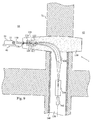
- Fig. 9 is a corresponding cross-sectional illustration of another embodiment of a radiation system according to the present invention.
- the gantry 100 is mainly arranged in a radiation-shielding wall or partition 71 separating two neighboring treatment rooms 61 and 62.
- This gantry embodiment 100 is in particular configured for providing horizontal beams 110 to the treatment volume 55 of the patient 50.
- the including units 124-126 of the radiation head 120 and the beam processing (guiding and scanning) system 104-106, 122 are similar to the corresponding units discussed above in connection with Fig. 7 and are not further described.
- rotation axes of the excentric gantries illustrated in Figs. 2 to 8 are horizontal or vertical as illustrated in Fig. 9, the present invention is not limited thereto.
- the rotation axis can have any angle from vertical to horizontal, somewhat dependent on how the beam is extracted from the accelerator and the range of variability needed clinically.
- Fig. 10 illustrates a cross-section of a portion of radiation system 1 with a gantry 100 providing oblique beams 110.
- the treatment beam 110 is deflected by the bending magnet 106 less than 90° in order to save power and to get oblique beams in multiple treatment rooms 61 and 62. Angles as low as 30° up to some 60° could be useful in special cases.
- the including units of the gantry 100 and radiation system 1 correspond to the units discussed above in connection with Fig. 7.
- Fig. 11 illustrates another possible design of the internal units of the beam scanning and bending system 104-106, 122 of the excentric gantry 100 of the present invention.
- This embodiment minimizes the diameter of the rotary gantry part 130 including the magnet 106 and treatment head 120.
- the incident (light ion) radiation beam preferably, first enters quadupoles 102. The beam then enters a bending and scanning magnet 104 that scans the beam in the plane of the drawing. The scanned beam is then bent in a (super-conducting) bending magnet 106.
- the bending magnet 106 preferably directs the beam into a second scanning magnet 122.
- This scanning magnet 122 and the collimators 124 and 126 where discussed in connection with Fig. 7.
- the radiation shielding 150 may also be included, calling for a somewhat smaller deflection in the magnet 104 than shown in the Fig. 11.
Applications Claiming Priority (2)
| Application Number | Priority Date | Filing Date | Title |
|---|---|---|---|
| US52608003P | 2003-12-02 | 2003-12-02 | |
| PCT/SE2004/001770 WO2005053794A1 (en) | 2003-12-02 | 2004-11-29 | Multiple room radiation treatment system |
Publications (2)
| Publication Number | Publication Date |
|---|---|
| EP1691890A1 EP1691890A1 (en) | 2006-08-23 |
| EP1691890B1 true EP1691890B1 (en) | 2008-01-23 |
Family
ID=34652412
Family Applications (1)
| Application Number | Title | Priority Date | Filing Date |
|---|---|---|---|
| EP04800421A Not-in-force EP1691890B1 (en) | 2003-12-02 | 2004-11-29 | Multiple room radiation treatment system |
Country Status (8)
| Country | Link |
|---|---|
| US (1) | US7531818B2 (ko) |
| EP (1) | EP1691890B1 (ko) |
| JP (1) | JP4616843B2 (ko) |
| KR (1) | KR101108806B1 (ko) |
| CN (1) | CN1889995B (ko) |
| AT (1) | ATE384553T1 (ko) |
| DE (1) | DE602004011560T2 (ko) |
| WO (1) | WO2005053794A1 (ko) |
Families Citing this family (137)
| Publication number | Priority date | Publication date | Assignee | Title |
|---|---|---|---|---|
| US9077022B2 (en) * | 2004-10-29 | 2015-07-07 | Medtronic, Inc. | Lithium-ion battery |
| JP4452848B2 (ja) * | 2004-12-13 | 2010-04-21 | 独立行政法人放射線医学総合研究所 | 荷電粒子線照射装置および回転ガントリ |
| DE102005035141A1 (de) * | 2005-07-22 | 2007-02-01 | GSI Gesellschaft für Schwerionenforschung mbH | Bestrahlungseinrichtung |
| EP1795229A1 (en) * | 2005-12-12 | 2007-06-13 | Ion Beam Applications S.A. | Device and method for positioning a patient in a radiation therapy apparatus |
| DE102006018635B4 (de) * | 2006-04-21 | 2008-01-24 | Siemens Ag | Bestrahlungsanlage mit einem Gantry-System mit einem gekrümmten Strahlführungsmagneten |
| US7402822B2 (en) * | 2006-06-05 | 2008-07-22 | Varian Medical Systems Technologies, Inc. | Particle beam nozzle transport system |
| JP4228018B2 (ja) * | 2007-02-16 | 2009-02-25 | 三菱重工業株式会社 | 医療装置 |
| DE102007029192B3 (de) * | 2007-06-25 | 2009-01-29 | Siemens Ag | Gantry mit Ausweichraum für eine Partikeltherapie-Anlage |
| JP5015821B2 (ja) * | 2008-02-21 | 2012-08-29 | 三菱電機株式会社 | 粒子線治療シミュレータ装置 |
| US10029122B2 (en) | 2008-05-22 | 2018-07-24 | Susan L. Michaud | Charged particle—patient motion control system apparatus and method of use thereof |
| US9782140B2 (en) | 2008-05-22 | 2017-10-10 | Susan L. Michaud | Hybrid charged particle / X-ray-imaging / treatment apparatus and method of use thereof |
| US8598543B2 (en) * | 2008-05-22 | 2013-12-03 | Vladimir Balakin | Multi-axis/multi-field charged particle cancer therapy method and apparatus |
| US8093564B2 (en) | 2008-05-22 | 2012-01-10 | Vladimir Balakin | Ion beam focusing lens method and apparatus used in conjunction with a charged particle cancer therapy system |
| US9056199B2 (en) | 2008-05-22 | 2015-06-16 | Vladimir Balakin | Charged particle treatment, rapid patient positioning apparatus and method of use thereof |
| US10137316B2 (en) * | 2008-05-22 | 2018-11-27 | Vladimir Balakin | Charged particle treatment, rapid patient positioning apparatus and method of use thereof |
| US8368038B2 (en) | 2008-05-22 | 2013-02-05 | Vladimir Balakin | Method and apparatus for intensity control of a charged particle beam extracted from a synchrotron |
| US8896239B2 (en) | 2008-05-22 | 2014-11-25 | Vladimir Yegorovich Balakin | Charged particle beam injection method and apparatus used in conjunction with a charged particle cancer therapy system |
| US10092776B2 (en) | 2008-05-22 | 2018-10-09 | Susan L. Michaud | Integrated translation/rotation charged particle imaging/treatment apparatus and method of use thereof |
| US9058910B2 (en) | 2008-05-22 | 2015-06-16 | Vladimir Yegorovich Balakin | Charged particle beam acceleration method and apparatus as part of a charged particle cancer therapy system |
| US8569717B2 (en) | 2008-05-22 | 2013-10-29 | Vladimir Balakin | Intensity modulated three-dimensional radiation scanning method and apparatus |
| US9044600B2 (en) | 2008-05-22 | 2015-06-02 | Vladimir Balakin | Proton tomography apparatus and method of operation therefor |
| US8129699B2 (en) | 2008-05-22 | 2012-03-06 | Vladimir Balakin | Multi-field charged particle cancer therapy method and apparatus coordinated with patient respiration |
| US8436327B2 (en) | 2008-05-22 | 2013-05-07 | Vladimir Balakin | Multi-field charged particle cancer therapy method and apparatus |
| US9737272B2 (en) | 2008-05-22 | 2017-08-22 | W. Davis Lee | Charged particle cancer therapy beam state determination apparatus and method of use thereof |
| US8309941B2 (en) | 2008-05-22 | 2012-11-13 | Vladimir Balakin | Charged particle cancer therapy and patient breath monitoring method and apparatus |
| EP2283710B1 (en) * | 2008-05-22 | 2018-07-11 | Vladimir Yegorovich Balakin | Multi-field charged particle cancer therapy apparatus |
| US8374314B2 (en) | 2008-05-22 | 2013-02-12 | Vladimir Balakin | Synchronized X-ray / breathing method and apparatus used in conjunction with a charged particle cancer therapy system |
| US8178859B2 (en) | 2008-05-22 | 2012-05-15 | Vladimir Balakin | Proton beam positioning verification method and apparatus used in conjunction with a charged particle cancer therapy system |
| US8378321B2 (en) | 2008-05-22 | 2013-02-19 | Vladimir Balakin | Charged particle cancer therapy and patient positioning method and apparatus |
| US9855444B2 (en) | 2008-05-22 | 2018-01-02 | Scott Penfold | X-ray detector for proton transit detection apparatus and method of use thereof |
| US8718231B2 (en) | 2008-05-22 | 2014-05-06 | Vladimir Balakin | X-ray tomography method and apparatus used in conjunction with a charged particle cancer therapy system |
| US10070831B2 (en) | 2008-05-22 | 2018-09-11 | James P. Bennett | Integrated cancer therapy—imaging apparatus and method of use thereof |
| US8144832B2 (en) * | 2008-05-22 | 2012-03-27 | Vladimir Balakin | X-ray tomography method and apparatus used in conjunction with a charged particle cancer therapy system |
| US8519365B2 (en) | 2008-05-22 | 2013-08-27 | Vladimir Balakin | Charged particle cancer therapy imaging method and apparatus |
| US9168392B1 (en) | 2008-05-22 | 2015-10-27 | Vladimir Balakin | Charged particle cancer therapy system X-ray apparatus and method of use thereof |
| US9910166B2 (en) | 2008-05-22 | 2018-03-06 | Stephen L. Spotts | Redundant charged particle state determination apparatus and method of use thereof |
| US9981147B2 (en) | 2008-05-22 | 2018-05-29 | W. Davis Lee | Ion beam extraction apparatus and method of use thereof |
| US9974978B2 (en) | 2008-05-22 | 2018-05-22 | W. Davis Lee | Scintillation array apparatus and method of use thereof |
| US8624528B2 (en) | 2008-05-22 | 2014-01-07 | Vladimir Balakin | Method and apparatus coordinating synchrotron acceleration periods with patient respiration periods |
| US9177751B2 (en) | 2008-05-22 | 2015-11-03 | Vladimir Balakin | Carbon ion beam injector apparatus and method of use thereof |
| US10143854B2 (en) | 2008-05-22 | 2018-12-04 | Susan L. Michaud | Dual rotation charged particle imaging / treatment apparatus and method of use thereof |
| US8957396B2 (en) | 2008-05-22 | 2015-02-17 | Vladimir Yegorovich Balakin | Charged particle cancer therapy beam path control method and apparatus |
| US9616252B2 (en) | 2008-05-22 | 2017-04-11 | Vladimir Balakin | Multi-field cancer therapy apparatus and method of use thereof |
| US8188688B2 (en) * | 2008-05-22 | 2012-05-29 | Vladimir Balakin | Magnetic field control method and apparatus used in conjunction with a charged particle cancer therapy system |
| US8975600B2 (en) | 2008-05-22 | 2015-03-10 | Vladimir Balakin | Treatment delivery control system and method of operation thereof |
| US8198607B2 (en) * | 2008-05-22 | 2012-06-12 | Vladimir Balakin | Tandem accelerator method and apparatus used in conjunction with a charged particle cancer therapy system |
| US10548551B2 (en) | 2008-05-22 | 2020-02-04 | W. Davis Lee | Depth resolved scintillation detector array imaging apparatus and method of use thereof |
| EP2283713B1 (en) | 2008-05-22 | 2018-03-28 | Vladimir Yegorovich Balakin | Multi-axis charged particle cancer therapy apparatus |
| US8487278B2 (en) * | 2008-05-22 | 2013-07-16 | Vladimir Yegorovich Balakin | X-ray method and apparatus used in conjunction with a charged particle cancer therapy system |
| US9737733B2 (en) | 2008-05-22 | 2017-08-22 | W. Davis Lee | Charged particle state determination apparatus and method of use thereof |
| US9579525B2 (en) | 2008-05-22 | 2017-02-28 | Vladimir Balakin | Multi-axis charged particle cancer therapy method and apparatus |
| US8288742B2 (en) * | 2008-05-22 | 2012-10-16 | Vladimir Balakin | Charged particle cancer therapy patient positioning method and apparatus |
| US8373145B2 (en) * | 2008-05-22 | 2013-02-12 | Vladimir Balakin | Charged particle cancer therapy system magnet control method and apparatus |
| US9095040B2 (en) | 2008-05-22 | 2015-07-28 | Vladimir Balakin | Charged particle beam acceleration and extraction method and apparatus used in conjunction with a charged particle cancer therapy system |
| US8373143B2 (en) | 2008-05-22 | 2013-02-12 | Vladimir Balakin | Patient immobilization and repositioning method and apparatus used in conjunction with charged particle cancer therapy |
| US8373146B2 (en) * | 2008-05-22 | 2013-02-12 | Vladimir Balakin | RF accelerator method and apparatus used in conjunction with a charged particle cancer therapy system |
| US8378311B2 (en) | 2008-05-22 | 2013-02-19 | Vladimir Balakin | Synchrotron power cycling apparatus and method of use thereof |
| US8399866B2 (en) | 2008-05-22 | 2013-03-19 | Vladimir Balakin | Charged particle extraction apparatus and method of use thereof |
| US8969834B2 (en) | 2008-05-22 | 2015-03-03 | Vladimir Balakin | Charged particle therapy patient constraint apparatus and method of use thereof |
| US8907309B2 (en) | 2009-04-17 | 2014-12-09 | Stephen L. Spotts | Treatment delivery control system and method of operation thereof |
| US10684380B2 (en) | 2008-05-22 | 2020-06-16 | W. Davis Lee | Multiple scintillation detector array imaging apparatus and method of use thereof |
| US9737734B2 (en) | 2008-05-22 | 2017-08-22 | Susan L. Michaud | Charged particle translation slide control apparatus and method of use thereof |
| US9744380B2 (en) | 2008-05-22 | 2017-08-29 | Susan L. Michaud | Patient specific beam control assembly of a cancer therapy apparatus and method of use thereof |
| US9498649B2 (en) | 2008-05-22 | 2016-11-22 | Vladimir Balakin | Charged particle cancer therapy patient constraint apparatus and method of use thereof |
| WO2009142550A2 (en) | 2008-05-22 | 2009-11-26 | Vladimir Yegorovich Balakin | Charged particle beam extraction method and apparatus used in conjunction with a charged particle cancer therapy system |
| US9682254B2 (en) | 2008-05-22 | 2017-06-20 | Vladimir Balakin | Cancer surface searing apparatus and method of use thereof |
| US8637833B2 (en) | 2008-05-22 | 2014-01-28 | Vladimir Balakin | Synchrotron power supply apparatus and method of use thereof |
| WO2009142545A2 (en) * | 2008-05-22 | 2009-11-26 | Vladimir Yegorovich Balakin | Charged particle cancer therapy patient positioning method and apparatus |
| US9155911B1 (en) | 2008-05-22 | 2015-10-13 | Vladimir Balakin | Ion source method and apparatus used in conjunction with a charged particle cancer therapy system |
| US7939809B2 (en) | 2008-05-22 | 2011-05-10 | Vladimir Balakin | Charged particle beam extraction method and apparatus used in conjunction with a charged particle cancer therapy system |
| US8129694B2 (en) * | 2008-05-22 | 2012-03-06 | Vladimir Balakin | Negative ion beam source vacuum method and apparatus used in conjunction with a charged particle cancer therapy system |
| US9937362B2 (en) | 2008-05-22 | 2018-04-10 | W. Davis Lee | Dynamic energy control of a charged particle imaging/treatment apparatus and method of use thereof |
| US8642978B2 (en) | 2008-05-22 | 2014-02-04 | Vladimir Balakin | Charged particle cancer therapy dose distribution method and apparatus |
| US8089054B2 (en) | 2008-05-22 | 2012-01-03 | Vladimir Balakin | Charged particle beam acceleration and extraction method and apparatus used in conjunction with a charged particle cancer therapy system |
| US8710462B2 (en) | 2008-05-22 | 2014-04-29 | Vladimir Balakin | Charged particle cancer therapy beam path control method and apparatus |
| US8229072B2 (en) * | 2008-07-14 | 2012-07-24 | Vladimir Balakin | Elongated lifetime X-ray method and apparatus used in conjunction with a charged particle cancer therapy system |
| US8627822B2 (en) | 2008-07-14 | 2014-01-14 | Vladimir Balakin | Semi-vertical positioning method and apparatus used in conjunction with a charged particle cancer therapy system |
| US8625739B2 (en) | 2008-07-14 | 2014-01-07 | Vladimir Balakin | Charged particle cancer therapy x-ray method and apparatus |
| JP2012519532A (ja) | 2009-03-04 | 2012-08-30 | ザクリトエ アクツィアニェールナエ オーブシチェストヴォ プロトム | 多方向荷電粒子線癌治療方法及び装置 |
| US9196388B2 (en) | 2009-12-07 | 2015-11-24 | Varian Medical Systems, Inc. | System and method for generating molybdenum-99 and metastable technetium-99, and other isotopes |
| DE102010009019B4 (de) | 2010-02-24 | 2012-04-19 | Siemens Aktiengesellschaft | Medizinisches, mit Röntgenstrahlen arbeitendes Gerät sowie Verfahren zum Betreiben eines solchen |
| JP2011182987A (ja) * | 2010-03-09 | 2011-09-22 | Sumitomo Heavy Ind Ltd | 加速粒子照射設備 |
| WO2011126805A2 (en) * | 2010-03-29 | 2011-10-13 | Procure Treatment Centers, Inc. | Intelligent particle beam allocation system and related method for treatment in multi-room medical centers |
| US10589128B2 (en) | 2010-04-16 | 2020-03-17 | Susan L. Michaud | Treatment beam path verification in a cancer therapy apparatus and method of use thereof |
| US10518109B2 (en) | 2010-04-16 | 2019-12-31 | Jillian Reno | Transformable charged particle beam path cancer therapy apparatus and method of use thereof |
| US10751551B2 (en) | 2010-04-16 | 2020-08-25 | James P. Bennett | Integrated imaging-cancer treatment apparatus and method of use thereof |
| US10625097B2 (en) | 2010-04-16 | 2020-04-21 | Jillian Reno | Semi-automated cancer therapy treatment apparatus and method of use thereof |
| US10349906B2 (en) | 2010-04-16 | 2019-07-16 | James P. Bennett | Multiplexed proton tomography imaging apparatus and method of use thereof |
| US9737731B2 (en) | 2010-04-16 | 2017-08-22 | Vladimir Balakin | Synchrotron energy control apparatus and method of use thereof |
| US10179250B2 (en) | 2010-04-16 | 2019-01-15 | Nick Ruebel | Auto-updated and implemented radiation treatment plan apparatus and method of use thereof |
| US10376717B2 (en) | 2010-04-16 | 2019-08-13 | James P. Bennett | Intervening object compensating automated radiation treatment plan development apparatus and method of use thereof |
| US11648420B2 (en) | 2010-04-16 | 2023-05-16 | Vladimir Balakin | Imaging assisted integrated tomography—cancer treatment apparatus and method of use thereof |
| US10086214B2 (en) | 2010-04-16 | 2018-10-02 | Vladimir Balakin | Integrated tomography—cancer treatment apparatus and method of use thereof |
| US10188877B2 (en) | 2010-04-16 | 2019-01-29 | W. Davis Lee | Fiducial marker/cancer imaging and treatment apparatus and method of use thereof |
| US10556126B2 (en) | 2010-04-16 | 2020-02-11 | Mark R. Amato | Automated radiation treatment plan development apparatus and method of use thereof |
| US10638988B2 (en) | 2010-04-16 | 2020-05-05 | Scott Penfold | Simultaneous/single patient position X-ray and proton imaging apparatus and method of use thereof |
| US10555710B2 (en) | 2010-04-16 | 2020-02-11 | James P. Bennett | Simultaneous multi-axes imaging apparatus and method of use thereof |
| EP2572360A4 (en) * | 2010-05-18 | 2015-12-16 | Veritas Medical Solutions Llc | COMPACT MODULAR PARTICULATE SYSTEM HAVING LAYERED BARRIERS |
| JP5670126B2 (ja) * | 2010-08-26 | 2015-02-18 | 住友重機械工業株式会社 | 荷電粒子線照射装置、荷電粒子線照射方法及び荷電粒子線照射プログラム |
| CN103222009B (zh) | 2010-09-08 | 2016-06-08 | 雷迪诺华公司 | 正电子发射器辐射系统 |
| US8481979B2 (en) * | 2010-09-09 | 2013-07-09 | Mitsubishi Electric Company | Particle beam therapy system with respiratory synchronization control |
| US8963112B1 (en) | 2011-05-25 | 2015-02-24 | Vladimir Balakin | Charged particle cancer therapy patient positioning method and apparatus |
| US20130066134A1 (en) * | 2011-08-16 | 2013-03-14 | Mark Carol | Multiplexed Radiation Therapy |
| JP5763218B2 (ja) * | 2012-01-16 | 2015-08-12 | 住友重機械工業株式会社 | 荷電粒子線照射システム |
| WO2013114619A1 (ja) * | 2012-02-03 | 2013-08-08 | 住友重機械工業株式会社 | 荷電粒子線照射装置 |
| US8933651B2 (en) | 2012-11-16 | 2015-01-13 | Vladimir Balakin | Charged particle accelerator magnet apparatus and method of use thereof |
| KR101410768B1 (ko) * | 2012-12-28 | 2014-06-24 | 한국원자력연구원 | 양성자 치료시설 |
| US10675487B2 (en) | 2013-12-20 | 2020-06-09 | Mevion Medical Systems, Inc. | Energy degrader enabling high-speed energy switching |
| US9962560B2 (en) | 2013-12-20 | 2018-05-08 | Mevion Medical Systems, Inc. | Collimator and energy degrader |
| DE212014000252U1 (de) * | 2014-02-26 | 2016-09-29 | Moshe Ein-Gal | Externe Strahlenradiotherapie |
| KR101568938B1 (ko) | 2014-07-30 | 2015-11-12 | 가톨릭대학교 산학협력단 | 양성자와 붕소 핵반응을 이용한 방사선 치료 및 진단기 |
| US9950194B2 (en) | 2014-09-09 | 2018-04-24 | Mevion Medical Systems, Inc. | Patient positioning system |
| CN104667437A (zh) * | 2015-03-25 | 2015-06-03 | 广东中能加速器科技有限公司 | 一种医用电子直线加速器分束线应用系统 |
| US10786689B2 (en) | 2015-11-10 | 2020-09-29 | Mevion Medical Systems, Inc. | Adaptive aperture |
| US9907981B2 (en) | 2016-03-07 | 2018-03-06 | Susan L. Michaud | Charged particle translation slide control apparatus and method of use thereof |
| US10037863B2 (en) | 2016-05-27 | 2018-07-31 | Mark R. Amato | Continuous ion beam kinetic energy dissipater apparatus and method of use thereof |
| JP6754847B2 (ja) * | 2016-07-04 | 2020-09-16 | 南京中硼▲聯▼康医▲療▼科技有限公司Neuboron Medtech Ltd. | 中性子治療装置 |
| US10925147B2 (en) | 2016-07-08 | 2021-02-16 | Mevion Medical Systems, Inc. | Treatment planning |
| CN106139420B (zh) * | 2016-07-29 | 2023-03-21 | 中国原子能科学研究院 | 基于回旋加速器的质子治疗系统 |
| CN106139421B (zh) * | 2016-07-29 | 2019-05-21 | 中国原子能科学研究院 | 一种错位布置的双固定室双束照射的质子治疗系统 |
| CN106621075B (zh) * | 2016-12-22 | 2021-01-08 | 上海联影医疗科技股份有限公司 | 放射治疗装置 |
| US11103730B2 (en) | 2017-02-23 | 2021-08-31 | Mevion Medical Systems, Inc. | Automated treatment in particle therapy |
| US10653892B2 (en) | 2017-06-30 | 2020-05-19 | Mevion Medical Systems, Inc. | Configurable collimator controlled using linear motors |
| GB2567672B (en) | 2017-10-20 | 2020-09-02 | Muir Ip Ltd | Radiation therapy system |
| CN107952178B (zh) * | 2017-12-13 | 2020-07-07 | 合肥中科离子医学技术装备有限公司 | 一种采用可移动屏蔽门紧凑布局的质子治疗系统 |
| CN109925612A (zh) * | 2017-12-18 | 2019-06-25 | 南京中硼联康医疗科技有限公司 | 中子捕获治疗系统 |
| WO2019119835A1 (zh) * | 2017-12-18 | 2019-06-27 | 南京中硼联康医疗科技有限公司 | 中子捕获治疗系统 |
| CN108744314B (zh) * | 2018-06-25 | 2020-10-02 | 西安大医集团股份有限公司 | 放射治疗设备 |
| CN113474040A (zh) * | 2019-01-10 | 2021-10-01 | 普罗诺瓦解决方案有限责任公司 | 紧凑型质子治疗系统和方法 |
| CN109646813A (zh) * | 2019-01-31 | 2019-04-19 | 陈大为 | 一种光谱治疗灯体及光谱治疗仪 |
| GB2583140B (en) * | 2019-04-18 | 2023-08-30 | Muir Ip Ltd | Radiation therapy system |
| US20230063755A1 (en) * | 2021-08-17 | 2023-03-02 | Varian Medical Systems, Inc. | Movable/replaceable high intensity target and multiple accelerator systems and methods |
| CN114796895A (zh) * | 2022-04-11 | 2022-07-29 | 中国科学院近代物理研究所 | 一种基于90度旋转束线的终端治疗系统及其操作方法 |
| CN114849084A (zh) * | 2022-04-11 | 2022-08-05 | 中国科学院近代物理研究所 | 一种基于90度旋转束线的治疗床及其操作方法 |
| EP4275742A1 (en) * | 2022-05-12 | 2023-11-15 | Paul Scherrer Institut | Compact beam transport system for multi-room particle therapy facility |
| CN115569310B (zh) * | 2022-09-01 | 2023-05-30 | 中国科学院近代物理研究所 | 一种基于组合旋转束线的辐照终端及应用 |
| CN116020062B (zh) * | 2023-01-13 | 2023-09-29 | 兰州科近泰基新技术有限责任公司 | 基于旋转束线的治疗终端 |
Family Cites Families (7)
| Publication number | Priority date | Publication date | Assignee | Title |
|---|---|---|---|---|
| US4870287A (en) * | 1988-03-03 | 1989-09-26 | Loma Linda University Medical Center | Multi-station proton beam therapy system |
| US5207223A (en) * | 1990-10-19 | 1993-05-04 | Accuray, Inc. | Apparatus for and method of performing stereotaxic surgery |
| JP2824363B2 (ja) * | 1992-07-15 | 1998-11-11 | 三菱電機株式会社 | ビーム供給装置 |
| US5433693A (en) | 1992-12-31 | 1995-07-18 | Ott; Karl O. | Neutron-capture therapy apparatus and method |
| JP3338332B2 (ja) * | 1997-05-28 | 2002-10-28 | 三菱電機株式会社 | 荷電粒子照射装置 |
| DE69841746D1 (de) * | 1998-09-11 | 2010-08-12 | Gsi Helmholtzzentrum Schwerionenforschung Gmbh | Ionenstrahl-Therapieanlage und Verfahren zum Betrieb der Anlage |
| CN2538292Y (zh) * | 2002-04-28 | 2003-03-05 | 李辉 | 推拉、折叠式介入防护屏 |
-
2004
- 2004-11-29 US US10/581,299 patent/US7531818B2/en not_active Expired - Fee Related
- 2004-11-29 EP EP04800421A patent/EP1691890B1/en not_active Not-in-force
- 2004-11-29 JP JP2006542529A patent/JP4616843B2/ja not_active Expired - Fee Related
- 2004-11-29 KR KR1020067012879A patent/KR101108806B1/ko not_active IP Right Cessation
- 2004-11-29 AT AT04800421T patent/ATE384553T1/de not_active IP Right Cessation
- 2004-11-29 CN CN2004800357530A patent/CN1889995B/zh not_active Expired - Fee Related
- 2004-11-29 DE DE602004011560T patent/DE602004011560T2/de active Active
- 2004-11-29 WO PCT/SE2004/001770 patent/WO2005053794A1/en active IP Right Grant
Also Published As
| Publication number | Publication date |
|---|---|
| KR101108806B1 (ko) | 2012-01-31 |
| KR20060116838A (ko) | 2006-11-15 |
| JP2007512897A (ja) | 2007-05-24 |
| DE602004011560T2 (de) | 2009-02-05 |
| EP1691890A1 (en) | 2006-08-23 |
| US20070131876A1 (en) | 2007-06-14 |
| CN1889995B (zh) | 2010-12-08 |
| CN1889995A (zh) | 2007-01-03 |
| JP4616843B2 (ja) | 2011-01-19 |
| US7531818B2 (en) | 2009-05-12 |
| WO2005053794A1 (en) | 2005-06-16 |
| DE602004011560D1 (de) | 2008-03-13 |
| ATE384553T1 (de) | 2008-02-15 |
Similar Documents
| Publication | Publication Date | Title |
|---|---|---|
| EP1691890B1 (en) | Multiple room radiation treatment system | |
| Pedroni et al. | The 200‐MeV proton therapy project at the Paul Scherrer Institute: Conceptual design and practical realization | |
| US6730921B2 (en) | Ion beam system for irradiating tumor tissues | |
| US11369807B2 (en) | Compact proton therapy systems and methods | |
| CA2249656C (en) | Radiation therapy and radiation surgery treatment system and methods of use of same | |
| EP1885452B1 (en) | Small field intensity modulated radiation therapy machine | |
| Pedroni et al. | Beam optics design of compact gantry for proton therapy | |
| US8613694B2 (en) | Method for biological modulation of radiation therapy | |
| EP3064252B1 (en) | Multipurpose radiotherapy system | |
| US9155912B2 (en) | Method and system for stereotactic intensity-modulated arc therapy | |
| CN102247658B (zh) | 放疗和成像装置 | |
| EP1514579A2 (en) | System and method for verifying the amount of radiation delivered to an object | |
| US20130066134A1 (en) | Multiplexed Radiation Therapy | |
| WO2009153832A1 (ja) | 治療台システム | |
| US20210031053A1 (en) | Radiation treatment head and radiation treatment device | |
| WO2014111869A2 (en) | An apparatus to deliver conformal radiotherapy using external beam cobalt 60 | |
| US11904188B2 (en) | Fully-spherical radiation therapy system | |
| EP2704797B1 (en) | Universal teletherapy treatment room arrangement | |
| Chu et al. | Performance specifications for proton medical facility | |
| Schreuder et al. | The non-orthogonal fixed beam arrangement for the second proton therapy facility at the National Accelerator Center | |
| WO2023238121A1 (en) | Installation of proton therapy equipment in existing radiotherapy treatment vaults | |
| Blattmann et al. | A horizontal proton beam line for the development of a scanning technique | |
| JP2022552715A (ja) | 対象のハドロン療法処置中のハドロンビームのモニタリング方法およびシステム | |
| Brown | Multileaf collimator and related apparatus |
Legal Events
| Date | Code | Title | Description |
|---|---|---|---|
| PUAI | Public reference made under article 153(3) epc to a published international application that has entered the european phase |
Free format text: ORIGINAL CODE: 0009012 |
|
| 17P | Request for examination filed |
Effective date: 20060703 |
|
| AK | Designated contracting states |
Kind code of ref document: A1 Designated state(s): AT BE BG CH CY CZ DE DK EE ES FI FR GB GR HU IE IS IT LI LU MC NL PL PT RO SE SI SK TR |
|
| DAX | Request for extension of the european patent (deleted) | ||
| GRAP | Despatch of communication of intention to grant a patent |
Free format text: ORIGINAL CODE: EPIDOSNIGR1 |
|
| GRAS | Grant fee paid |
Free format text: ORIGINAL CODE: EPIDOSNIGR3 |
|
| GRAA | (expected) grant |
Free format text: ORIGINAL CODE: 0009210 |
|
| AK | Designated contracting states |
Kind code of ref document: B1 Designated state(s): AT BE BG CH CY CZ DE DK EE ES FI FR GB GR HU IE IS IT LI LU MC NL PL PT RO SE SI SK TR |
|
| REG | Reference to a national code |
Ref country code: GB Ref legal event code: FG4D |
|
| REG | Reference to a national code |
Ref country code: CH Ref legal event code: EP |
|
| REG | Reference to a national code |
Ref country code: IE Ref legal event code: FG4D |
|
| REF | Corresponds to: |
Ref document number: 602004011560 Country of ref document: DE Date of ref document: 20080313 Kind code of ref document: P |
|
| REG | Reference to a national code |
Ref country code: SE Ref legal event code: TRGR |
|
| REG | Reference to a national code |
Ref country code: CH Ref legal event code: NV Representative=s name: ING. MARCO ZARDI C/O M. ZARDI & CO. S.A. |
|
| NLV1 | Nl: lapsed or annulled due to failure to fulfill the requirements of art. 29p and 29m of the patents act | ||
| PG25 | Lapsed in a contracting state [announced via postgrant information from national office to epo] |
Ref country code: IS Free format text: LAPSE BECAUSE OF FAILURE TO SUBMIT A TRANSLATION OF THE DESCRIPTION OR TO PAY THE FEE WITHIN THE PRESCRIBED TIME-LIMIT Effective date: 20080523 Ref country code: ES Free format text: LAPSE BECAUSE OF FAILURE TO SUBMIT A TRANSLATION OF THE DESCRIPTION OR TO PAY THE FEE WITHIN THE PRESCRIBED TIME-LIMIT Effective date: 20080504 Ref country code: FI Free format text: LAPSE BECAUSE OF FAILURE TO SUBMIT A TRANSLATION OF THE DESCRIPTION OR TO PAY THE FEE WITHIN THE PRESCRIBED TIME-LIMIT Effective date: 20080123 |
|
| PG25 | Lapsed in a contracting state [announced via postgrant information from national office to epo] |
Ref country code: BG Free format text: LAPSE BECAUSE OF FAILURE TO SUBMIT A TRANSLATION OF THE DESCRIPTION OR TO PAY THE FEE WITHIN THE PRESCRIBED TIME-LIMIT Effective date: 20080423 Ref country code: AT Free format text: LAPSE BECAUSE OF FAILURE TO SUBMIT A TRANSLATION OF THE DESCRIPTION OR TO PAY THE FEE WITHIN THE PRESCRIBED TIME-LIMIT Effective date: 20080123 |
|
| PG25 | Lapsed in a contracting state [announced via postgrant information from national office to epo] |
Ref country code: BE Free format text: LAPSE BECAUSE OF FAILURE TO SUBMIT A TRANSLATION OF THE DESCRIPTION OR TO PAY THE FEE WITHIN THE PRESCRIBED TIME-LIMIT Effective date: 20080123 Ref country code: PT Free format text: LAPSE BECAUSE OF FAILURE TO SUBMIT A TRANSLATION OF THE DESCRIPTION OR TO PAY THE FEE WITHIN THE PRESCRIBED TIME-LIMIT Effective date: 20080623 Ref country code: SI Free format text: LAPSE BECAUSE OF FAILURE TO SUBMIT A TRANSLATION OF THE DESCRIPTION OR TO PAY THE FEE WITHIN THE PRESCRIBED TIME-LIMIT Effective date: 20080123 Ref country code: PL Free format text: LAPSE BECAUSE OF FAILURE TO SUBMIT A TRANSLATION OF THE DESCRIPTION OR TO PAY THE FEE WITHIN THE PRESCRIBED TIME-LIMIT Effective date: 20080123 |
|
| PG25 | Lapsed in a contracting state [announced via postgrant information from national office to epo] |
Ref country code: SK Free format text: LAPSE BECAUSE OF FAILURE TO SUBMIT A TRANSLATION OF THE DESCRIPTION OR TO PAY THE FEE WITHIN THE PRESCRIBED TIME-LIMIT Effective date: 20080123 Ref country code: NL Free format text: LAPSE BECAUSE OF FAILURE TO SUBMIT A TRANSLATION OF THE DESCRIPTION OR TO PAY THE FEE WITHIN THE PRESCRIBED TIME-LIMIT Effective date: 20080123 Ref country code: CZ Free format text: LAPSE BECAUSE OF FAILURE TO SUBMIT A TRANSLATION OF THE DESCRIPTION OR TO PAY THE FEE WITHIN THE PRESCRIBED TIME-LIMIT Effective date: 20080123 Ref country code: DK Free format text: LAPSE BECAUSE OF FAILURE TO SUBMIT A TRANSLATION OF THE DESCRIPTION OR TO PAY THE FEE WITHIN THE PRESCRIBED TIME-LIMIT Effective date: 20080123 |
|
| EN | Fr: translation not filed | ||
| PG25 | Lapsed in a contracting state [announced via postgrant information from national office to epo] |
Ref country code: RO Free format text: LAPSE BECAUSE OF FAILURE TO SUBMIT A TRANSLATION OF THE DESCRIPTION OR TO PAY THE FEE WITHIN THE PRESCRIBED TIME-LIMIT Effective date: 20080123 |
|
| PLBE | No opposition filed within time limit |
Free format text: ORIGINAL CODE: 0009261 |
|
| STAA | Information on the status of an ep patent application or granted ep patent |
Free format text: STATUS: NO OPPOSITION FILED WITHIN TIME LIMIT |
|
| 26N | No opposition filed |
Effective date: 20081024 |
|
| PG25 | Lapsed in a contracting state [announced via postgrant information from national office to epo] |
Ref country code: EE Free format text: LAPSE BECAUSE OF FAILURE TO SUBMIT A TRANSLATION OF THE DESCRIPTION OR TO PAY THE FEE WITHIN THE PRESCRIBED TIME-LIMIT Effective date: 20080123 Ref country code: FR Free format text: LAPSE BECAUSE OF FAILURE TO SUBMIT A TRANSLATION OF THE DESCRIPTION OR TO PAY THE FEE WITHIN THE PRESCRIBED TIME-LIMIT Effective date: 20081114 |
|
| PG25 | Lapsed in a contracting state [announced via postgrant information from national office to epo] |
Ref country code: MC Free format text: LAPSE BECAUSE OF NON-PAYMENT OF DUE FEES Effective date: 20081130 |
|
| PG25 | Lapsed in a contracting state [announced via postgrant information from national office to epo] |
Ref country code: CY Free format text: LAPSE BECAUSE OF FAILURE TO SUBMIT A TRANSLATION OF THE DESCRIPTION OR TO PAY THE FEE WITHIN THE PRESCRIBED TIME-LIMIT Effective date: 20080123 |
|
| PG25 | Lapsed in a contracting state [announced via postgrant information from national office to epo] |
Ref country code: IT Free format text: LAPSE BECAUSE OF FAILURE TO SUBMIT A TRANSLATION OF THE DESCRIPTION OR TO PAY THE FEE WITHIN THE PRESCRIBED TIME-LIMIT Effective date: 20080123 |
|
| PG25 | Lapsed in a contracting state [announced via postgrant information from national office to epo] |
Ref country code: IE Free format text: LAPSE BECAUSE OF NON-PAYMENT OF DUE FEES Effective date: 20081201 |
|
| PG25 | Lapsed in a contracting state [announced via postgrant information from national office to epo] |
Ref country code: HU Free format text: LAPSE BECAUSE OF FAILURE TO SUBMIT A TRANSLATION OF THE DESCRIPTION OR TO PAY THE FEE WITHIN THE PRESCRIBED TIME-LIMIT Effective date: 20080724 Ref country code: LU Free format text: LAPSE BECAUSE OF NON-PAYMENT OF DUE FEES Effective date: 20081129 |
|
| PG25 | Lapsed in a contracting state [announced via postgrant information from national office to epo] |
Ref country code: TR Free format text: LAPSE BECAUSE OF FAILURE TO SUBMIT A TRANSLATION OF THE DESCRIPTION OR TO PAY THE FEE WITHIN THE PRESCRIBED TIME-LIMIT Effective date: 20080123 |
|
| PG25 | Lapsed in a contracting state [announced via postgrant information from national office to epo] |
Ref country code: GR Free format text: LAPSE BECAUSE OF FAILURE TO SUBMIT A TRANSLATION OF THE DESCRIPTION OR TO PAY THE FEE WITHIN THE PRESCRIBED TIME-LIMIT Effective date: 20080424 |
|
| PGFP | Annual fee paid to national office [announced via postgrant information from national office to epo] |
Ref country code: DE Payment date: 20151204 Year of fee payment: 12 Ref country code: GB Payment date: 20151125 Year of fee payment: 12 Ref country code: CH Payment date: 20151125 Year of fee payment: 12 |
|
| PGFP | Annual fee paid to national office [announced via postgrant information from national office to epo] |
Ref country code: SE Payment date: 20151126 Year of fee payment: 12 |
|
| REG | Reference to a national code |
Ref country code: DE Ref legal event code: R119 Ref document number: 602004011560 Country of ref document: DE |
|
| REG | Reference to a national code |
Ref country code: CH Ref legal event code: PL |
|
| REG | Reference to a national code |
Ref country code: SE Ref legal event code: EUG |
|
| GBPC | Gb: european patent ceased through non-payment of renewal fee |
Effective date: 20161129 |
|
| PG25 | Lapsed in a contracting state [announced via postgrant information from national office to epo] |
Ref country code: LI Free format text: LAPSE BECAUSE OF NON-PAYMENT OF DUE FEES Effective date: 20161130 Ref country code: CH Free format text: LAPSE BECAUSE OF NON-PAYMENT OF DUE FEES Effective date: 20161130 |
|
| PG25 | Lapsed in a contracting state [announced via postgrant information from national office to epo] |
Ref country code: SE Free format text: LAPSE BECAUSE OF NON-PAYMENT OF DUE FEES Effective date: 20161130 |
|
| PG25 | Lapsed in a contracting state [announced via postgrant information from national office to epo] |
Ref country code: GB Free format text: LAPSE BECAUSE OF NON-PAYMENT OF DUE FEES Effective date: 20161129 Ref country code: DE Free format text: LAPSE BECAUSE OF NON-PAYMENT OF DUE FEES Effective date: 20170601 |