EP1682795B1 - Apparatus incorporating a motion damper - Google Patents
Apparatus incorporating a motion damper Download PDFInfo
- Publication number
- EP1682795B1 EP1682795B1 EP04800513A EP04800513A EP1682795B1 EP 1682795 B1 EP1682795 B1 EP 1682795B1 EP 04800513 A EP04800513 A EP 04800513A EP 04800513 A EP04800513 A EP 04800513A EP 1682795 B1 EP1682795 B1 EP 1682795B1
- Authority
- EP
- European Patent Office
- Prior art keywords
- damper
- stages
- wall
- vehicle
- actuator
- Prior art date
- Legal status (The legal status is an assumption and is not a legal conclusion. Google has not performed a legal analysis and makes no representation as to the accuracy of the status listed.)
- Not-in-force
Links
Images


Classifications
-
- F—MECHANICAL ENGINEERING; LIGHTING; HEATING; WEAPONS; BLASTING
- F16—ENGINEERING ELEMENTS AND UNITS; GENERAL MEASURES FOR PRODUCING AND MAINTAINING EFFECTIVE FUNCTIONING OF MACHINES OR INSTALLATIONS; THERMAL INSULATION IN GENERAL
- F16F—SPRINGS; SHOCK-ABSORBERS; MEANS FOR DAMPING VIBRATION
- F16F7/00—Vibration-dampers; Shock-absorbers
- F16F7/12—Vibration-dampers; Shock-absorbers using plastic deformation of members
- F16F7/125—Units with a telescopic-like action as one member moves into, or out of a second member
-
- B—PERFORMING OPERATIONS; TRANSPORTING
- B60—VEHICLES IN GENERAL
- B60N—SEATS SPECIALLY ADAPTED FOR VEHICLES; VEHICLE PASSENGER ACCOMMODATION NOT OTHERWISE PROVIDED FOR
- B60N2/00—Seats specially adapted for vehicles; Arrangement or mounting of seats in vehicles
- B60N2/02—Seats specially adapted for vehicles; Arrangement or mounting of seats in vehicles the seat or part thereof being movable, e.g. adjustable
- B60N2/22—Seats specially adapted for vehicles; Arrangement or mounting of seats in vehicles the seat or part thereof being movable, e.g. adjustable the back-rest being adjustable
- B60N2/23—Seats specially adapted for vehicles; Arrangement or mounting of seats in vehicles the seat or part thereof being movable, e.g. adjustable the back-rest being adjustable by linear actuators, e.g. linear screw mechanisms
- B60N2/231—Seats specially adapted for vehicles; Arrangement or mounting of seats in vehicles the seat or part thereof being movable, e.g. adjustable the back-rest being adjustable by linear actuators, e.g. linear screw mechanisms by hydraulic actuators
-
- B—PERFORMING OPERATIONS; TRANSPORTING
- B60—VEHICLES IN GENERAL
- B60N—SEATS SPECIALLY ADAPTED FOR VEHICLES; VEHICLE PASSENGER ACCOMMODATION NOT OTHERWISE PROVIDED FOR
- B60N2/00—Seats specially adapted for vehicles; Arrangement or mounting of seats in vehicles
- B60N2/24—Seats specially adapted for vehicles; Arrangement or mounting of seats in vehicles for particular purposes or particular vehicles
- B60N2/42—Seats specially adapted for vehicles; Arrangement or mounting of seats in vehicles for particular purposes or particular vehicles the seat constructed to protect the occupant from the effect of abnormal g-forces, e.g. crash or safety seats
- B60N2/4207—Seats specially adapted for vehicles; Arrangement or mounting of seats in vehicles for particular purposes or particular vehicles the seat constructed to protect the occupant from the effect of abnormal g-forces, e.g. crash or safety seats characterised by the direction of the g-forces
- B60N2/4214—Seats specially adapted for vehicles; Arrangement or mounting of seats in vehicles for particular purposes or particular vehicles the seat constructed to protect the occupant from the effect of abnormal g-forces, e.g. crash or safety seats characterised by the direction of the g-forces longitudinal
-
- B—PERFORMING OPERATIONS; TRANSPORTING
- B60—VEHICLES IN GENERAL
- B60N—SEATS SPECIALLY ADAPTED FOR VEHICLES; VEHICLE PASSENGER ACCOMMODATION NOT OTHERWISE PROVIDED FOR
- B60N2/00—Seats specially adapted for vehicles; Arrangement or mounting of seats in vehicles
- B60N2/24—Seats specially adapted for vehicles; Arrangement or mounting of seats in vehicles for particular purposes or particular vehicles
- B60N2/42—Seats specially adapted for vehicles; Arrangement or mounting of seats in vehicles for particular purposes or particular vehicles the seat constructed to protect the occupant from the effect of abnormal g-forces, e.g. crash or safety seats
- B60N2/427—Seats or parts thereof displaced during a crash
- B60N2/42727—Seats or parts thereof displaced during a crash involving substantially rigid displacement
- B60N2/42745—Seats or parts thereof displaced during a crash involving substantially rigid displacement of the back-rest
-
- B—PERFORMING OPERATIONS; TRANSPORTING
- B60—VEHICLES IN GENERAL
- B60P—VEHICLES ADAPTED FOR LOAD TRANSPORTATION OR TO TRANSPORT, TO CARRY, OR TO COMPRISE SPECIAL LOADS OR OBJECTS
- B60P1/00—Vehicles predominantly for transporting loads and modified to facilitate loading, consolidating the load, or unloading
- B60P1/04—Vehicles predominantly for transporting loads and modified to facilitate loading, consolidating the load, or unloading with a tipping movement of load-transporting element
- B60P1/16—Vehicles predominantly for transporting loads and modified to facilitate loading, consolidating the load, or unloading with a tipping movement of load-transporting element actuated by fluid-operated mechanisms
- B60P1/162—Vehicles predominantly for transporting loads and modified to facilitate loading, consolidating the load, or unloading with a tipping movement of load-transporting element actuated by fluid-operated mechanisms the hydraulic system itself
-
- B—PERFORMING OPERATIONS; TRANSPORTING
- B60—VEHICLES IN GENERAL
- B60R—VEHICLES, VEHICLE FITTINGS, OR VEHICLE PARTS, NOT OTHERWISE PROVIDED FOR
- B60R21/00—Arrangements or fittings on vehicles for protecting or preventing injuries to occupants or pedestrians in case of accidents or other traffic risks
- B60R21/34—Protecting non-occupants of a vehicle, e.g. pedestrians
-
- F—MECHANICAL ENGINEERING; LIGHTING; HEATING; WEAPONS; BLASTING
- F15—FLUID-PRESSURE ACTUATORS; HYDRAULICS OR PNEUMATICS IN GENERAL
- F15B—SYSTEMS ACTING BY MEANS OF FLUIDS IN GENERAL; FLUID-PRESSURE ACTUATORS, e.g. SERVOMOTORS; DETAILS OF FLUID-PRESSURE SYSTEMS, NOT OTHERWISE PROVIDED FOR
- F15B15/00—Fluid-actuated devices for displacing a member from one position to another; Gearing associated therewith
- F15B15/08—Characterised by the construction of the motor unit
- F15B15/10—Characterised by the construction of the motor unit the motor being of diaphragm type
-
- F—MECHANICAL ENGINEERING; LIGHTING; HEATING; WEAPONS; BLASTING
- F15—FLUID-PRESSURE ACTUATORS; HYDRAULICS OR PNEUMATICS IN GENERAL
- F15B—SYSTEMS ACTING BY MEANS OF FLUIDS IN GENERAL; FLUID-PRESSURE ACTUATORS, e.g. SERVOMOTORS; DETAILS OF FLUID-PRESSURE SYSTEMS, NOT OTHERWISE PROVIDED FOR
- F15B15/00—Fluid-actuated devices for displacing a member from one position to another; Gearing associated therewith
- F15B15/08—Characterised by the construction of the motor unit
- F15B15/14—Characterised by the construction of the motor unit of the straight-cylinder type
- F15B15/16—Characterised by the construction of the motor unit of the straight-cylinder type of the telescopic type
-
- F—MECHANICAL ENGINEERING; LIGHTING; HEATING; WEAPONS; BLASTING
- F15—FLUID-PRESSURE ACTUATORS; HYDRAULICS OR PNEUMATICS IN GENERAL
- F15B—SYSTEMS ACTING BY MEANS OF FLUIDS IN GENERAL; FLUID-PRESSURE ACTUATORS, e.g. SERVOMOTORS; DETAILS OF FLUID-PRESSURE SYSTEMS, NOT OTHERWISE PROVIDED FOR
- F15B15/00—Fluid-actuated devices for displacing a member from one position to another; Gearing associated therewith
- F15B15/19—Pyrotechnical actuators
-
- F—MECHANICAL ENGINEERING; LIGHTING; HEATING; WEAPONS; BLASTING
- F16—ENGINEERING ELEMENTS AND UNITS; GENERAL MEASURES FOR PRODUCING AND MAINTAINING EFFECTIVE FUNCTIONING OF MACHINES OR INSTALLATIONS; THERMAL INSULATION IN GENERAL
- F16F—SPRINGS; SHOCK-ABSORBERS; MEANS FOR DAMPING VIBRATION
- F16F7/00—Vibration-dampers; Shock-absorbers
- F16F7/12—Vibration-dampers; Shock-absorbers using plastic deformation of members
- F16F7/123—Deformation involving a bending action, e.g. strap moving through multiple rollers, folding of members
-
- B—PERFORMING OPERATIONS; TRANSPORTING
- B60—VEHICLES IN GENERAL
- B60R—VEHICLES, VEHICLE FITTINGS, OR VEHICLE PARTS, NOT OTHERWISE PROVIDED FOR
- B60R21/00—Arrangements or fittings on vehicles for protecting or preventing injuries to occupants or pedestrians in case of accidents or other traffic risks
- B60R21/34—Protecting non-occupants of a vehicle, e.g. pedestrians
- B60R21/38—Protecting non-occupants of a vehicle, e.g. pedestrians using means for lifting bonnets
Definitions
- the present invention relates to an apparatus incorporating a motion damper and a linear actuator. More specifically, the invention relates to a motion damper used in connection with vehicle safety systems.
- dampers are used to limit the transfer of kinetic energy between two connected objects.
- shock absorbers in vehicular suspension systems use a common type of damper.
- These suspension systems use a spring, such as a steel coil, to allow each wheel to move up when the wheel encounters a bump, and to rapidly move back down after the wheel passes the bump.
- the spring such as a steel coil
- the vehicle would bounce up and down several times after each bump is encountered, making it uncomfortable to ride in the vehicle and also making it difficult to control the vehicle. The danger of this situation is amplified significantly if a surface on which the vehicle is operated is coated with rain or snow.
- the suspension system needs a way to dissipate the energy stored in the spring after the wheel encounters an aberration.
- a damper performs this function and limits the transfer of the kinetic energy, or vibrations, of the wheels of the vehicle to the passenger compartment of the vehicle.
- dampers have been designed in many different ways.
- One type of damper involves a piston tightly fitted within a chamber.
- the piston has a head and an arm connected to the head.
- the piston head slides within the chamber. Seals around the perimeter of the piston head prevent leakage of the fluid between the piston head and the chamber wall.
- the piston head divides the chamber into a first and a second sub-chamber.
- the piston arm protrudes out of an opening in the chamber. Again, seals are required to prevent fluid leakage through the opening.
- the piston arm is connected to a first object, such as the wheel of a vehicle, while the chamber is connected to a second object, such as the frame of the vehicle.
- a bi-directional limiting port in the piston head permits the controlled transfer of fluid from the first to the second sub-chamber and vice versa.
- the limiting port may be designed to allow fluid to flow through the piston head at varying rates.
- a small limiting port provides for relatively slow transfer of fluid between the sub-chambers and inhibits virtually all oscillation, thus providing a firm ride and nimble handling when used in a shock absorber for a vehicle.
- a large limiting port permits rapid transfer of fluid between the sub-chambers and, thus, yields a smooth ride when used in a shock absorber.
- two unidirectional limiting ports are positioned in the piston head. One port permits the fluid to move from the first sub-chamber to the second sub-chamber, while the other port permits the fluid to move from the second sub-chamber to the first sub-chamber.
- a disparate damping effect may be provided, depending on the direction the piston head moves within the chamber.
- dampers that are very simple in design. However, dampers can be, and often are, much more complex. For instance, some dampers provide varying damping levels through the use of multiple chambers, peripheral passages, or electronic control systems.
- dampers suffer from a number of limitations.
- these dampers are relatively complex and, as a result, are expensive, particularly if the damper is intended to be used only a single time.
- damping effect is generally proportional to the length or size of the damper. That is to say, longer and larger dampers generally provide a superior damping effect. As a result, dampers that provide a substantial damping effect are often bulky.
- EP0777064 discloses a device for limiting the tensile load on a vehicle safety belt, comprising a deformable metal plate which is secured around its periphery to a base plate for anchoring to the vehicle and which comprises, in an un-deployed state, a series of concentric corrugations around a central portion which is connectable by a bolt with a seat belt mounting bracket.
- the apparatus of the present invention has been developed in response to the present state of the art, and in particular, in response to the problems and needs in the art that have not yet been fully resolved by current dampers.
- the present invention provides a motion damper that is compact and simple in design, and is thus inexpensive to manufacture.
- apparatus incorporating a motion damper comprising:
- the damper wall is preferably generally cylindrical in shape and prior to deployment of the stages surrounds the damper stages.
- the first end of the damper wall is flexibly attached to the largest damper stage, which is adjacent to the damper wall.
- the second end of the damper wall is attached to a lip which extends away from the second end of the wall. The lip may be used to secure the motion damper to another object, such as a part of a vehicle.
- each of the damper stages is also generally cylindrical in shape.
- the damper stages and damper wall also have a nested relationship. This means that each of the stages is sized to fit within an adjacent damper stage or the damper wall. Because of the nested relationship, the convoluted member is compact and may be used in small spaces.
- damper wall and damper stages are each flexibly attached to an adjacent damper stage or the damper wall such that the damper stages may telescopically extend away from the damper wall along a longitudinal axis of the convoluted member. Accordingly, each of the damper stages may change in position relative to each other and relative to the damper wall.
- the damper stages may be made from various types of malleable materials, including various types of metals or plastics.
- the smallest damper stage is flexibly attached to the damper head, which is a broad, flat surface.
- the convoluted member is made from a malleable material, the convoluted member can be used to dampen motion between a first object connected to the damper head and a second object connected to the lip or damper wall. As the damper wall moves away from the damper head the stages change in position relative to each other and the wall to absorb the kinetic energy. Thus, the convoluted member functions as a motion damper.
- the motion damper is used to dampen the motion of the linear actuator.
- the actuator wall, piston stages, and piston wall define, at least in part, an interior chamber.
- pressurized fluid may be forcefully injected into the interior chamber.
- the piston stages deploy, or extend telescopically away from, the actuator wall to generate linear motion along a longitudinal axis of the linear actuator.
- the dampened actuator operates in the following way in the context of a motor vehicle.
- the lip of the motion damper is attached to a first part of a vehicle, and the fluid generator of the linear actuator is attached to a second part of the vehicle.
- the first and second parts of the vehicle may be pivotally attached to each other.
- the piston stages deploy to generate linear motion, moving the first part of the vehicle away from the second part of the vehicle.
- the motion damper then deploys to absorb the kinetic energy of the first part of the vehicle.
- the damper stages change in position relative to each other to provide a more gradual deceleration of the first part of the vehicle. Were it not for the motion damper, the first part of the vehicle might be damaged by the rapid deceleration resulting from the deployment of the linear actuator.
- the dampened actuator can be used in a number of different ways.
- the dampened actuator may be used to slightly raise the hood of a vehicle in the event of a vehicle-pedestrian accident such that the hood is used as a "crumple zone" to minimize the danger that the occupant's head or torso will impact the engine block of the vehicle.
- the dampened actuator could be used to tilt, or recline, a vehicle occupant's seat about a rear pivot point in the event of a roll-over accident so that the occupant's head is positioned further away from the roof in case the roof collapses.
- the motion damper provides for a more gradual deceleration of a part of a vehicle, such as the hood or seat, attached to the linear actuator in each of these instances.
- the motion damper provides substantial advantages over conventional dampers.
- the motion damper is compact and can be used in the tight confines of a vehicle.
- the motion damper is also simple in design and, thus, can be manufactured in a cost-effective manner.
- the motion damper can be stored for long periods of time without significantly increasing the risk of deterioration or malfunction.
- the phrases “connected to,” “coupled to,” and “in communication with” refer to any form of interaction between two or more entities, including mechanical, electrical, magnetic, electromagnetic, and thermal interaction.
- the phrase “attached to” refers to a form of mechanical coupling that restricts relative translation or rotation between the attached objects. Items, parts, or divisions that are “attached” may mechanically interact because of a mechanical fastener, such as a clip, pin, or adhesive, or because the items are integrally formed.
- the phrases “flexibly attached to” and “pivotally attached to” refer to forms of mechanical coupling that permit relative rotation or relative translation, respectively, while restricting other relative motion.
- directly attached to refers to a form of attachment by which the attached items are either in direct contact, or are only separated by a single fastener, adhesive, or other attachment mechanism.
- first attachment refers to items that are in direct physical contact with each other, although the items may not be attached together.
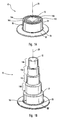
- FIG. 1A a perspective side view of a convoluted member 10 is shown.
- the convoluted member 10 may be used in connection with either a motion damper or a linear actuator, both of which are shown in Figures 3-6 .
- the convoluted member 10 of Figure 1A is shown prior to deployment, while Figure 1B shows the convoluted member 10 following deployment.
- the convoluted member 10 includes a head 12, stages 14a-d, and a wall 16.
- the head 12 is a broad, flat surface and can be used, for example, to secure or attach the convoluted member 10 to another object.
- the head 12 is referred to as a "piston head.”
- the term "damper head” will be used to refer to the head 12.
- the stages 14 of the convoluted member 10 Prior to deployment of the convoluted member 10, the stages 14 of the convoluted member 10 include a series of concentric folds in alternating directions formed in a malleable material. The stages 14 are of a successively smaller size. When the convoluted member 10 is used as part of a linear actuator, the stages 14 will be referred to as “piston stages.” The term “damper stages” will be used to refer to the stages 14 when the convoluted member 10 is used as a motion damper.
- a smallest stage 14a is attached to the head 12.
- the term "attached to” refers to mechanical interaction between two items because of a fastener or because the items are integrally formed.
- the head 12 is integrally formed with the stages 14.
- a mechanical fastener or fasteners such as an adhesive, bolt, or rivet, may be used to attach the stages 14 to the head 12.
- the convoluted member 10 also includes a wall 16.
- the illustrated wall 16 is flexibly attached to the largest stage 14d.
- the wall 16 extends around a longitudinal axis 20 of the convoluted member 10.
- the stages 14 Prior to deployment of the stages 14, the stages 14 are generally disposed within, or circumscribed by, the wall 16.
- the wall 16 includes a first end 24 and second end 26.
- the first end 24 of the wall 16 is flexibly attached to the largest stage 14d.
- the term "damper wall” will be used to refer to the wall 16.
- the term "actuator wall” will be used to refer to the wall 16.
- a lip 28 extends away from the second end 26 of the wall 16.
- the lip 28 can be used to secure the convoluted member 10 to another object, such as a part of a vehicle (shown in Figures 5 and 6 ).
- the illustrated lip 28 extends a uniform distance away from the wall 16.
- the lip 28 may include one or more discrete portions that extend away from the wall 16.
- FIG. 1B a perspective side view of the convoluted member 10 is shown after deployment.
- the stages 14a-d have telescopically extended away from the wall 16 and have unfolded in the process.
- the stages 14 change in position relative to each other and the wall 16.
- the stages 14 deploy along the longitudinal axis 20 of the convoluted member 10.
- FIG 1B more clearly shows that the wall 16 and the stages 14 are successively smaller in size. In particular, moving from the wall 16 to the head 12, the wall 16 and stages 14 are successively smaller in size.
- the wall 16 is not necessarily disposed outside of the stages 14.
- successively larger stages 14 are disposed around the wall 16.
- the wall 16 and stages 14 are of a successively smaller size when moving from the head 12 toward the wall 16.
- the convoluted member 10 may be used in connection with a linear actuator or may be used as a motion damper to absorb kinetic energy.
- a fluid may forcefully be injected into the convoluted member to deploy the piston stages 14.
- the damper stages 14 extend, or even contract, to absorb kinetic energy when the damper wall 16 and damper head 12 are connected to objects that are moving either away from or toward each other. Accordingly, the stages 14 change position relative to each other or telescopically extend away from the wall 16 upon the application of a force. This force may drive the stages 14 further away from each other or may drive the stages 14 closer to each other.
- the convoluted member 10 can be made from various types of malleable, or energy absorbing, materials, including certain types of metals or plastics. Because the convoluted member is made from a malleable material, the convoluted member 10 is a single-use convoluted member. Thus, during deployment, the convoluted member 10 becomes deformed and should thereafter be discarded or recycled.
- the illustrated stages 14 and wall 16 are generally cylindrical in shape. However, the stages 14 and wall 16 may be formed in other shapes, such as a generally octagonal, hexagonal, rectangular, or square shape.
- FIG. 2 illustrates a cross-section view of a convoluted member 10 before deployment.
- Figure 2 shows that each stage 14 is flexibly attached to at least one adjacent stage 14. More specifically, each stage 14 is flexibly attached to an adjacent stage 14 by an internal fold 30 or an external fold 32. As stated above, the largest stage 14d is flexibly attached to the first end 24 of the wall 16, while the smallest stage 14a is attached to the head 12. Each stage 14 is flexibly attached to an adjacent stage 14 such that the stages 14 may telescopically extend away from the wall 16.
- the wall 16, stages 14, and head 12 may be integrally formed, as shown, or may comprise physically distinct components joined together using, for example, adhesives, rivets, hinges, other types of pivoting members, or a combination of the foregoing.
- the embodiment of the convoluted member 10 shown in Figures 1-3 includes four stages 14. Of course, the number of stages 14 may be varied within the scope of this invention. Also, the stages 14, as illustrated, are each about the same height, but stages 14 of varying sizes also come within the scope of this invention.
- the flexible attachment between the stages 14 and between the largest stage 14d and the wall 16 may be achieved in a number of different ways.
- the stages 14 and wall 16 may be connected using a malleable or flexible material.
- a plurality of hinges or other types of pivoting members may be used.
- the wall 16 and stages 14 may simply be formed from a malleable or flexible material, as shown in Figure 2 .
- the stages 14 and wall 16 have a nested relationship. This means that each of the stages 14 is sized to fit within an adjacent stage 14 or the wall 16. Because of the nested relationship, the convoluted member 10 is compact and may be used in small spaces.
- the head 12, stages 14 and wall 16 define, at least in part, an interior chamber 34.
- pressurized fluid is injected into the interior chamber 34 to deploy the piston stages 14 of the linear actuator and generate linear motion.
- Figure 2 also shows that the lip 28 is attached to the second end 26 of the wall 16.
- the wall 16 and lip 28 are integrally formed, but, in an alternative embodiment, the wall 16 and lip 28 may be physically separate components that are attached to each other.
- the lip 28 shown in Figure 2 is generally perpendicular to the wall 16, but may be disposed at other angles in relation to the wall 16 in alternative configurations.
- the dampened actuator 40 includes both a motion damper 42 and linear actuator 44.
- the motion damper 42 is positioned on top of and is attached to the linear actuator 44.
- the motion damper 42 and linear actuator 44 are coaxial with each other. More specifically, a longitudinal axis 50 of the motion damper 42 is coaxial with a longitudinal axis 52 of the linear actuator 44.
- the motion damper 42 is comprised of a convoluted member 10 that is made from an energy absorbing material. Accordingly, the damper stages 14 telescopically extend away from, or are pushed toward, the damper wall 16 to absorb the kinetic energy of an object attached to the motion damper 42.
- the linear actuator 44 has a convoluted member 10 attached to and in fluid communication with the fluid generator 54.
- a portion of the actuator wall 16 is cut away to show the piston stages 14.
- the fluid generator 54 produces a pressurized gas, liquid, or foam to deploy, or telescopically extend, the piston stages 14 of the linear actuator 44.
- the fluid generator 54 can use pyrotechnic methods, or methods for releasing compressed fluids, or a combination of the foregoing to generate the pressurized fluid.
- the fluid generator 54 is attached to the lip 28 of the convoluted member 10 of the linear actuator 44.
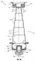
- FIG. 4A a cross-sectional view of a dampened actuator 40 after deployment of the linear actuator 44 is illustrated. As shown, the motion damper 42 has not yet been deployed. The damper stages 14 are still relatively close to each other such that the damper stages 14 are substantially disposed within the damper wall 16.
- the actuator wall 16 and actuator stages 14 define, at least in part, an interior chamber 34.
- the fluid generator 54 is in fluid communication with the interior chamber 34.
- the fluid generator 54 comprises a housing 58 containing gas generant 60 and an initiator 62.
- the initiator 62 activates the gas generant 60 to produce pressurized inflation gas.
- the pressurized inflation gas pushes against the piston stages 14.
- the amount of pressurized inflation gas produced by the fluid generator 54 depends on the specific use of the linear actuator 44. In the embodiment shown im Figure 4A , the pressure of the inflation gas is sufficient to fully extend each piston stage 14. To be more precise, the piston stages 14 have fully extended away from the piston wall 16 and increased a distance between each piston stage 14 to generate rapid linear motion along the longitudinal axis 52 of the linear actuator 44.
- the damper head 12 is attached to the piston head 12 using a rivet 64.
- the use of the rivet 64 is only illustrative.
- Other types of mechanical fasteners, such as adhesives or a nut and bolt, may be used attach the damper head 12 to the piston head 12.
- the convoluted member 10 of the motion damper 42 and the convoluted member 10 of the linear actuator 44 may be integrally formed.
- the linear actuator 44 and/or motion damper 42 optionally includes one or more attachment brackets 66 to permit pivotal connection of the dampened actuator 40 to an object, such a part of a vehicle, which is illustrated in Figures 5 and 6 .
- a pivotal connection is achieved when, for example, a U-shaped bolt (shown in Figure 6B ) is positioned in an opening 67 in the attachment bracket 66 and then the U-shaped bolt is secured to the object.
- the fluid generator 54 is remote to the interior chamber 34.
- a gas guide (not shown) conveys the pressurized fluid generated by the fluid generator 54 to the interior chamber 34.
- the open end 68 of the actuator wall 16 is enclosed so that the pressurized fluid deploys the piston stages 14 rather than exiting through the open end 68 of the actuator wall 16.
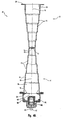
- FIG. 4B is a cross-sectional view illustrating a dampened actuator 40 after deployment of the motion damper 42 and linear actuator 44. Following deployment of the linear actuator 44, strong inertial forces are applied to the motion damper 42. As a result, each damper stage 14 changes in position relative to an adjacent damper stage 14. More specifically, the damper stages 14 move further apart from each other along the longitudinal axis 50 of the motion damper 42 and extend telescopically away from the damper wall 16. As a result of the damping effect, the lip 28 of the motion damper 42 decelerates more slowly than the piston head 12. Thus, the motion damper 42 dampens the motion of the linear actuator 44 and provides a more gradual deceleration of an object that is connected to the lip 28 of the dampened actuator 40.
- the illustrated pedestrian safety system 74 includes an impact sensor 78 in communication with two dampened actuators 40.
- the impact sensor 78 determines when the vehicle 72 has impacted an object, such as a pedestrian.
- the illustrated impact sensor 78 is located in the front bumper 80 of the vehicle 72.
- the sensor 78 could be embodied as an electronic control unit (ECU) that senses abnormal acceleration or deceleration of the vehicle 72.
- ECU electronice control unit
- Wiring 82 for example, may be used to transmit an electrical signal from the impact sensor 78 to the dampened actuators 40.
- a hood 86 which is pivotally attached to a portion of the vehicle 72, includes a pivoting end 88 and a remote end 90.
- the motion damper 42 of each dampened actuator 40 is connected to hood 86 near the pivoting end 88, while the linear actuator 44 of each dampened actuator 40 is connected to another part of the vehicle 72 that is located within the engine compartment 94, such as the frame or body 96 of the vehicle 72.
- the linear actuators 44 could be connected to the hood 86 near the pivoting end 88, while the motion dampers 42 could be connected to the frame or body 96.
- the dampened actuators 40 could be positioned at various locations on the hood 86.
- the dampened actuators 40 could be positioned near the remote end 90 of the hood 86, or at other positions between or on the pivoting and remote ends 88, 90 of the hood 86.
- the linear actuator 44 and motion damper 42 may include one or more attachment brackets 66 (shown in Figure 4A ) to permit pivotal attachment of the linear actuator 44 to the body 96 and pivotal attachment of the motion damper 42 to the remote end 90 of the hood 86.
- attachment brackets 66 shown in Figure 4A
- various techniques including selective connection of the dampened actuator 40 to the hood 86, may be used to permit opening and closing of the hood 86 during normal usage.
- the linear actuators 44 When the dampened actuators 40 receive the signal, the linear actuators 44 inflate and deploy the piston stages 14. As a result, the hood 86 is rapidly lifted. The motion dampers 42 then deploy to absorb the kinetic energy of the hood 86, as shown in Figure 5 . The damper stages 14 change in position relative to each other to provide a more gradual deceleration of the hood 86. Were it not for the motion dampers 42, the hood 86 might be damaged by the rapid acceleration and deceleration resulting from deployment of the linear actuators 44. If so, automobile manufacturers would be less likely to use the pedestrian safety system 74 because manufacturers, or the end user, would be required to replace or repair the hood 86 of the vehicle 72, even when the hood 86 was not otherwise damaged by the accident.
- the purpose of rapidly elevating the hood 86 in the event of a pedestrian impact is to limit injuries to the pedestrian. Frequently, in a vehicle-pedestrian accident, the pedestrian will rotate such that the pedestrian's head, or upper body, impact the hood 86, and then the engine block of the vehicle 72 at a high rate of speed. Rapidly raising the hood 86 using the pedestrian safety system 74 transforms the hood 86 into a "crumple zone," such that hood 86 more gradually decelerates the pedestrian to minimize the severity of the pedestrian's injuries.
- the safety system 102 includes an accident sensor 104, such as an ECU, in communication with one or more dampened actuators 40.
- an accident sensor 104 such as an ECU
- the accident sensor 104 determines that the vehicle 100 has been involved in an accident, the accident sensor 104 transmits a signal through wiring 82 to the dampened actuator 40.
- the accident sensor 104 may determine when the vehicle 100 becomes inverted or rolls over and send a signal in response thereto.
- the illustrated seat 106 is pivotally attached to the vehicle 100 and, thus, includes a pivot point 108 and a distal end 110.
- the seat 106 may include shear pins 111 which are severed by the sudden forceful movement of the distal end 110 of the seat 106. Shear pins 111 prevent the seat 106 from pivoting until an accident is detected.
- the linear actuator 44 of the dampened actuator 40 is connected to a floor 112 of the vehicle 100 and the motion damper 42 of the dampened actuator 40 is connected to the distal end 110 of the seat 106.
- the linear actuator 44 could be connected to the distal end 110 of the seat 106, while the motion damper 42 could be connected to floor 112 of the vehicle 100.
- the linear actuator 44 deploys and reclines the seat 106. Thereafter, the motion damper 42 deploys to provide a more gradual deceleration of the seat 106 to minimize discomfort to the occupant 114. As a result, the seat 106 moves into a reclined position, as shown in phantom in Figure 6A .
- the reclined seat 106 provides additional clearance 116 between the roof 118 and the occupant 114. Therefore, in an accident in which the roof 118 may collapse, the reclined position of the seat 106 decreases the risk that the occupant 114 will be impacted by the roof 118 of the vehicle 100.
- FIG. 6B an enlarged perspective view of the dampened actuator 40 of the rollover safety system 102 is shown in a deployed condition. As illustrated, the stages 14, 14 of both the motion damper 42 and linear actuator 44 are in a deployed condition. Accordingly, the seat 106 is in a reclined position, as shown in phantom in Figure 6A .
- the linear actuator 44 includes an attachment bracket 66 that permits pivotal connection of the dampened actuator 40 to the floor 112 using a U-shaped bolt 120 and two nuts 122. This pivotal connection permits the dampened actuator 40 to rotate relative to the floor 112 as the seat 106 pivots away from the floor 112 without contorting, and possibly damaging, the dampened actuator 40.
- an angle 124 between a longitudinal axis 126 of the dampened actuator 40 and the floor 112 may change without damaging or twisting the dampened actuator 40.
- both the linear actuator 44 and motion damper 42 include an attachment bracket 66 to permit pivotal connection of the dampened actuator 40 to both the seat 106 and floor 112.
- attachment bracket 66 to permit pivotal connection of the dampened actuator 40 to both the seat 106 and floor 112.
- the motion damper provides substantial advantages over conventional dampers.
- the motion damper is compact and can be used in the tight confines of a vehicle.
- the motion damper is also simple in design and, thus, can be manufactured in a cost-effective manner.
- the motion damper can be stored for long periods of time without significantly increasing the risk of deterioration or malfunction.
- the motion damper is ideally suited for many types of vehicle safety systems such as the examples discussed above.
Applications Claiming Priority (2)
| Application Number | Priority Date | Filing Date | Title |
|---|---|---|---|
| US10/701,734 US7182191B2 (en) | 2002-07-11 | 2003-11-05 | Motion damper |
| PCT/US2004/036202 WO2005047727A1 (en) | 2003-11-05 | 2004-11-01 | Motion damper |
Publications (2)
| Publication Number | Publication Date |
|---|---|
| EP1682795A1 EP1682795A1 (en) | 2006-07-26 |
| EP1682795B1 true EP1682795B1 (en) | 2009-09-09 |
Family
ID=34590696
Family Applications (1)
| Application Number | Title | Priority Date | Filing Date |
|---|---|---|---|
| EP04800513A Not-in-force EP1682795B1 (en) | 2003-11-05 | 2004-11-01 | Apparatus incorporating a motion damper |
Country Status (6)
| Country | Link |
|---|---|
| US (1) | US7182191B2 (ja) |
| EP (1) | EP1682795B1 (ja) |
| JP (1) | JP4890257B2 (ja) |
| AT (1) | ATE442537T1 (ja) |
| DE (1) | DE602004023109D1 (ja) |
| WO (1) | WO2005047727A1 (ja) |
Families Citing this family (31)
| Publication number | Priority date | Publication date | Assignee | Title |
|---|---|---|---|---|
| US8123263B2 (en) * | 2001-09-27 | 2012-02-28 | Shape Corp. | Energy management beam |
| US7303040B2 (en) * | 2004-05-18 | 2007-12-04 | Autolive Asp, Inc. | Active vehicle hood system and method |
| US7578513B2 (en) * | 2004-12-15 | 2009-08-25 | Research Machine Development, Inc. | Inflating safety apparatus for leaf spring trailers and vehicles |
| DE102005024357A1 (de) * | 2005-05-27 | 2006-11-30 | Bayerische Motoren Werke Ag | Anordnung einer Frontklappe an einem Fahrzeug |
| EP1738973A1 (en) * | 2005-06-27 | 2007-01-03 | IEE INTERNATIONAL ELECTRONICS & ENGINEERING S.A. | Safety system for pedestrian protection |
| US7469885B2 (en) * | 2005-10-24 | 2008-12-30 | The Boeing Company | Compliant coupling force control system |
| DE102005051657A1 (de) * | 2005-10-28 | 2007-05-03 | GM Global Technology Operations, Inc., Detroit | Pyrotechnischer Aktuator |
| FR2893688B1 (fr) * | 2005-11-21 | 2010-03-05 | Visteon Global Tech Inc | Dispositif absorbeur d'energie de forme tronconique et element de remplissage comprenant plusieurs tels dispositifs |
| CN102180137B (zh) * | 2005-11-23 | 2013-06-19 | 沙普公司 | 用于在车辆发生碰撞时吸收能量的方法和可变能量管理系统 |
| US7377580B1 (en) * | 2007-03-10 | 2008-05-27 | Nicholas Samir Ekladyous | Multi-tier structure for car body hood |
| DE102007012137A1 (de) * | 2007-03-12 | 2008-09-18 | Benteler Automobiltechnik Gmbh | Crashbox und Kraftfahrzeug-Stoßfängeranordnung |
| US7695052B2 (en) * | 2007-03-30 | 2010-04-13 | Ford Global Technologies, Llc | Front rail having controlled thickness for energy absorption |
| WO2009016981A1 (ja) * | 2007-07-27 | 2009-02-05 | Kabushiki Kaisha Toyota Chuo Kenkyusho | 展開構造体及び衝撃吸収装置 |
| US20090045612A1 (en) * | 2007-08-15 | 2009-02-19 | Autoliv Asp, Inc. | Flameless method to open a cold gas inflator burst disk |
| US7959228B2 (en) * | 2008-08-13 | 2011-06-14 | Honda Motor Co., Ltd. | Method for loading a child or child seat into a vehicle |
| GB0904343D0 (en) * | 2009-03-13 | 2009-04-29 | Linde Ag | Vehicle structures |
| WO2010151651A2 (en) * | 2009-06-24 | 2010-12-29 | Shape Corp. | Energy absorber with double-acting crush lobes |
| JP5632142B2 (ja) * | 2009-07-14 | 2014-11-26 | 新日鐵住金株式会社 | クラッシュボックス |
| US8671967B2 (en) * | 2009-08-07 | 2014-03-18 | Autoliv Asp, Inc. | Relief valve |
| JP5507971B2 (ja) * | 2009-11-16 | 2014-05-28 | アイシン精機株式会社 | 衝撃吸収具及び車両用バンパ装置 |
| US8276955B2 (en) * | 2010-03-26 | 2012-10-02 | Ford Global Technologies, Llc | Zero stack-up telescopically collapsible energy absorbing rail and bracket assembly |
| US8607703B2 (en) * | 2010-04-09 | 2013-12-17 | Bae Systems Information And Electronic Systems Integration Inc. | Enhanced reliability miniature piston actuator for an electronic thermal battery initiator |
| DE102011012421A1 (de) * | 2011-02-21 | 2012-08-23 | Raimund Rerucha | Spanneinrichtung, insbesondere für Schläuche |
| US8934948B2 (en) | 2011-04-22 | 2015-01-13 | Blackberry Limited | Low profile air damper |
| US8596681B1 (en) | 2012-05-30 | 2013-12-03 | Nissan North America, Inc. | Internal deployable vehicle panel assembly |
| US9403498B2 (en) | 2013-03-20 | 2016-08-02 | Shiloh Industries, Inc. | Energy absorbing assembly for vehicle |
| US20150132056A1 (en) * | 2013-11-08 | 2015-05-14 | Tyson Silva | Soft crash-barrier impact-attenuation system, device, and method |
| CN104632777A (zh) * | 2014-12-17 | 2015-05-20 | 华国洋 | 一种气缸缓冲器装置 |
| CN105201955B (zh) * | 2015-11-03 | 2016-08-17 | 温州泓呈祥科技有限公司 | 一种紧凑压缩缸 |
| US11400839B2 (en) * | 2020-09-22 | 2022-08-02 | Ford Global Technologies, Llc | Energy absorbing vehicle seat |
| US20220372805A1 (en) * | 2021-05-18 | 2022-11-24 | Curtis D. Randolph | Lift mechanism for vehicle hoods |
Family Cites Families (78)
| Publication number | Priority date | Publication date | Assignee | Title |
|---|---|---|---|---|
| US731354A (en) | 1902-06-06 | 1903-06-16 | Weston M Fulton | Collapsible vessel for atmospheric motors. |
| US1986273A (en) | 1932-07-02 | 1935-01-01 | Dwight A Leffingwell | Lifting jack |
| US3039347A (en) | 1957-08-08 | 1962-06-19 | Conn Ltd C G | Percussive type electric musical instrument |
| US3106131A (en) | 1961-05-24 | 1963-10-08 | Aircraft Armaments Inc | Cartridge actuated device |
| US3199288A (en) | 1963-03-20 | 1965-08-10 | Joseph A Nahas | Explosively actuated piston driver |
| US3565398A (en) | 1968-12-23 | 1971-02-23 | Goodrich Co B F | Pneumatic bag jack |
| US3715130A (en) | 1969-11-05 | 1973-02-06 | I Harada | Shock absorbing device for protecting a rider in a high speed vehicle such as automobile |
| AU458138B2 (en) | 1971-11-30 | 1975-02-20 | Nissan Motor Company Limited | Collision sensor for vehicle safety device |
| JPS4893045A (ja) | 1972-03-14 | 1973-12-01 | ||
| DE2262293C3 (de) * | 1972-12-20 | 1980-12-04 | Dr.Ing.H.C. F. Porsche Ag, 7000 Stuttgart | Stoßenergie absorbierendes Deformationselement für Kraftfahrzeuge, insbesondere Personenkraftwagen |
| DE2352179A1 (de) | 1973-10-17 | 1975-04-30 | Daimler Benz Ag | Stosschutzvorrichtung fuer ein kraftfahrzeug |
| GB1491208A (en) | 1973-11-21 | 1977-11-09 | Oleo Int Holdings Ltd | Liquid dampers |
| DE2426938C3 (de) * | 1974-06-04 | 1981-04-23 | Volkswagenwerk Ag, 3180 Wolfsburg | Stoßdämpfer |
| DE2427764A1 (de) * | 1974-06-08 | 1976-01-02 | Volkswagenwerk Ag | Stossfaengeranordnung fuer ein mit laengstraegern ausgeruestetes fahrzeug |
| US4091621A (en) | 1975-06-02 | 1978-05-30 | Networks Electronic Corp. | Pyrotechnic piston actuator |
| US4026590A (en) * | 1976-06-14 | 1977-05-31 | Holm Alan F | Folding bumper arrangement |
| US4037821A (en) | 1976-08-10 | 1977-07-26 | The United States Of America As Represented By The Secretary Of The Army | Telescoping retractor |
| JPS5912910Y2 (ja) | 1978-08-25 | 1984-04-18 | 株式会社日本自動車部品総合研究所 | シ−トベルト引締め装置の逆戻り防止装置 |
| US4560145A (en) | 1979-04-09 | 1985-12-24 | Widmer Stanley W | Air bag jack |
| IT1126990B (it) | 1980-03-20 | 1986-05-21 | Romanazzi Spa | Perfezionamento nei martinetti telescopici a sfilamenti multipli particolarmente per cassoni ribaltabili di veicoli |
| US4360228A (en) | 1980-11-28 | 1982-11-23 | Rasmussen Eldon S | Bumper apparatus |
| US4514002A (en) | 1982-03-08 | 1985-04-30 | John D. McIntosh | Two-position bumper |
| DE3313713A1 (de) | 1983-04-15 | 1984-10-25 | Messerschmitt-Bölkow-Blohm GmbH, 8000 München | Beschleunigungs-entsicherung |
| US4582351A (en) | 1983-11-25 | 1986-04-15 | Edwards Sherman J | Atlas bumper lift |
| US4687189A (en) | 1985-01-26 | 1987-08-18 | Kurt Stoll | Short stroke actuator |
| US4932697A (en) | 1988-12-29 | 1990-06-12 | Hun Yang C | Brake actuated automatic extending bumper |
| US5052732A (en) * | 1990-04-02 | 1991-10-01 | Renco Supply, Inc. | Crash attenuator utilizing fibrous honeycomb material |
| DE4113031A1 (de) * | 1991-04-20 | 1992-10-22 | Teves Gmbh Co Ohg Alfred | Stossfaengersystem mit einem ausfahrbaren stossfaenger fuer fahrzeuge |
| DE4131734A1 (de) | 1991-09-24 | 1993-04-01 | Schimmelpfennig Karl Heinz | Sich bei einer kollision selbsttaetig absenkender nutzfahrzeug-unterfahrschutz |
| US5293973A (en) * | 1991-12-16 | 1994-03-15 | Volkswagen Ag | Deformation member having an eversion portion |
| FR2685741A1 (fr) * | 1991-12-31 | 1993-07-02 | Thomson Brandt Armements | Verin pyrotechnique a course amortie. |
| DE4206022C2 (de) | 1992-02-27 | 1997-07-03 | Man Nutzfahrzeuge Ag | Aufprallvorrichtung für Nutzfahrzeuge |
| DE4330216C2 (de) | 1993-09-07 | 1995-08-17 | Daimler Benz Aerospace Ag | Transportable Berge- und Notausrüstung |
| IT1272731B (it) | 1993-10-18 | 1997-06-26 | Luciano Migliori | Attuatore lineare con ammortizzatore pneumatico regolabile in posizione |
| DE4417835A1 (de) * | 1994-05-20 | 1995-11-23 | Lignotock Gmbh | Stoßabsorber zur Verbesserung der Sicherheit in Fahrgastzellen von Kraftfahrzeugen |
| US5431087A (en) * | 1994-06-15 | 1995-07-11 | Kambara; Goro | Extended stroke linear actuator assembly |
| DE4433212C1 (de) * | 1994-09-17 | 1996-01-25 | Daimler Benz Aerospace Ag | Vorrichtung für Hydraulikkreis |
| US5520428A (en) * | 1994-10-27 | 1996-05-28 | Bell; Foyster G. | Movable bumper for vehicles |
| DE59505435D1 (de) * | 1994-12-23 | 1999-04-29 | Alusuisse Lonza Services Ag | Stossstange für Fahrzeuge |
| US5624143A (en) * | 1995-05-15 | 1997-04-29 | Waldschmitt; Tom | Drop down bumper |
| FR2741924B1 (fr) | 1995-11-30 | 1998-02-20 | Peugeot | Dispositif limiteur d'effort en traction |
| US5695242A (en) * | 1996-02-15 | 1997-12-09 | Breed Automotive Technology, Inc. | Seat cushion restraint system |
| FR2745621B1 (fr) | 1996-03-04 | 1998-05-29 | Peugeot | Dispositif absorbeur de chocs notamment pour vehicules automobiles |
| US5810427A (en) * | 1996-03-18 | 1998-09-22 | Hartmann; Albrecht | Motor vehicle |
| US5632518A (en) * | 1996-04-15 | 1997-05-27 | The United States Of America As Represented By The Secretary Of The Army | Rear impact trailer guard |
| US5639117A (en) * | 1996-06-05 | 1997-06-17 | Lockheed Martin Corporation | Vehicle occupant restraint apparatus |
| US5749425A (en) * | 1996-06-07 | 1998-05-12 | Ford Global Technologies, Inc. | Vehicle hood check and damping mechanism |
| DE19623196C1 (de) * | 1996-06-11 | 1998-01-08 | Bosch Gmbh Robert | Radarsensor für den Einsatz in Kraftfahrzeugen |
| DE19724628A1 (de) | 1996-06-27 | 1998-01-02 | Volkswagen Ag | Insassen-Schutzvorrichtung für ein Kraftfahrzeug |
| US5713596A (en) * | 1996-07-01 | 1998-02-03 | Lockheed Martin Corporation | Liquid propellant inflation apparatus for deploying an inflatable member |
| DE29612781U1 (de) * | 1996-07-23 | 1996-11-21 | Trw Repa Gmbh | Pyrotechnische Linearantriebseinrichtung für einen Gurtstraffer |
| US6039347A (en) * | 1997-02-03 | 2000-03-21 | General Dynamics Armament Systems, Inc. | Liquid propellant airbag inflator with dual telescoping pistons |
| GB9706164D0 (en) * | 1997-03-25 | 1997-05-14 | Hope Tech Dev Ltd | Bumper assembly |
| GB2330335A (en) * | 1997-10-14 | 1999-04-21 | Alliedsignal Ltd | Load limiting seat belt restraint |
| GB9800048D0 (en) | 1998-01-02 | 1998-03-04 | Breed Automotive Tech | Safety restraint |
| DE19803156C1 (de) * | 1998-01-28 | 1999-08-12 | Daimler Chrysler Ag | Energieabsorbierende Deformationsanordnung |
| GB2335004B (en) | 1998-03-05 | 2002-02-27 | Mbm Technology Ltd | Telescopic piston |
| US6398243B1 (en) | 1998-08-14 | 2002-06-04 | Link Mfg Ltd. | Direct acting air suspension system |
| US6089628A (en) * | 1998-09-02 | 2000-07-18 | Ford Global Technologies, Inc. | Stiffener assembly for bumper system of motor vehicles |
| US5967573A (en) * | 1998-10-29 | 1999-10-19 | General Motors Corporation | Bumper energy absorber |
| US6183042B1 (en) * | 1998-12-21 | 2001-02-06 | Albert W. Unrath | Mobile apparatus for securely retrieving and placing markers on a surface and method therefor |
| US6474489B2 (en) * | 1999-03-12 | 2002-11-05 | Thomas S. Payne | Collision attenuator |
| FR2796021B1 (fr) * | 1999-07-05 | 2001-10-19 | Peugeot Citroen Automobiles Sa | Poutre de pare-chocs pour vehicules automobiles |
| US6312049B1 (en) * | 1999-07-01 | 2001-11-06 | Ford Global Technologies, Inc. | Programmable seat back damper assembly for seats |
| DE10042221A1 (de) * | 1999-09-02 | 2001-08-09 | Om Corp | Stoßdämpfer für ein Fahrzeug, das plastische Verformungen ausnutzt |
| JP3380537B2 (ja) * | 1999-09-02 | 2003-02-24 | オーエム工業株式会社 | 車輌の衝撃吸収装置 |
| DE19945844A1 (de) | 1999-09-24 | 2001-03-29 | Sachsenfeuerwerk Gmbh | Druckbeaufschlagbare Betätigungseinrichtung mit pyrotechnischer Gaserzeugung |
| DE19946408A1 (de) | 1999-09-28 | 2001-05-03 | Siemens Restraint System Gmbh | System zum Anheben und Absenken eienr Motorhaube eines Kraftfahrzeuges |
| CN2389084Y (zh) * | 1999-09-28 | 2000-07-26 | 李博良 | 改良的大卡车追尾防护装置 |
| US6340142B1 (en) * | 2000-07-10 | 2002-01-22 | Shih-Hsiung Li | Clamp device for holding a radar sensor on a bumper of an automobile |
| JP3857029B2 (ja) | 2000-09-19 | 2006-12-13 | 本田技研工業株式会社 | 車両用センサシステム |
| WO2002055343A1 (en) | 2001-01-11 | 2002-07-18 | Universal Propulsion Company, Inc. | Bumper airbag and system |
| US6756707B2 (en) | 2001-01-26 | 2004-06-29 | Tol-O-Matic, Inc. | Electric actuator |
| JP2002331888A (ja) * | 2001-05-10 | 2002-11-19 | Om Kogyo Kk | バンパ取付構造 |
| GB2386937B (en) * | 2002-03-28 | 2005-03-02 | Visteon Global Tech Inc | A collapsible support |
| US6854574B2 (en) * | 2002-05-29 | 2005-02-15 | Asteer Co., Ltd. | Shock absorber |
| US6837518B2 (en) * | 2002-08-23 | 2005-01-04 | L&W Engineering Incorporated | Reinforcement structure for instrument panel |
| JP4219189B2 (ja) * | 2003-02-28 | 2009-02-04 | 株式会社アステア | 車体メンバに対するバンパ補強材の支持構造 |
-
2003
- 2003-11-05 US US10/701,734 patent/US7182191B2/en not_active Expired - Fee Related
-
2004
- 2004-11-01 WO PCT/US2004/036202 patent/WO2005047727A1/en active Application Filing
- 2004-11-01 DE DE602004023109T patent/DE602004023109D1/de active Active
- 2004-11-01 EP EP04800513A patent/EP1682795B1/en not_active Not-in-force
- 2004-11-01 JP JP2006539578A patent/JP4890257B2/ja not_active Expired - Fee Related
- 2004-11-01 AT AT04800513T patent/ATE442537T1/de not_active IP Right Cessation
Also Published As
| Publication number | Publication date |
|---|---|
| US7182191B2 (en) | 2007-02-27 |
| JP2007510877A (ja) | 2007-04-26 |
| EP1682795A1 (en) | 2006-07-26 |
| US20040089988A1 (en) | 2004-05-13 |
| JP4890257B2 (ja) | 2012-03-07 |
| DE602004023109D1 (de) | 2009-10-22 |
| ATE442537T1 (de) | 2009-09-15 |
| WO2005047727A1 (en) | 2005-05-26 |
Similar Documents
| Publication | Publication Date | Title |
|---|---|---|
| EP1682795B1 (en) | Apparatus incorporating a motion damper | |
| US6588526B1 (en) | Front hood assembly | |
| EP1842745B1 (en) | A bonnet bumpstop for a vehicle | |
| EP1497570B1 (en) | Collision energy-absorbing device | |
| KR100857909B1 (ko) | 차량의 안전 장치 | |
| US7290810B2 (en) | Device for absorption of impact energy on an automobile | |
| US6964316B1 (en) | Front opening hood assembly | |
| JP4140953B2 (ja) | 車両用安全機構 | |
| US20050257980A1 (en) | Active vehicle hood system and method | |
| US6769715B2 (en) | Responsive energy absorbing device for a steering column | |
| KR20070101767A (ko) | 차량용 스티어링 휠 리트랙팅 디바이스 | |
| EP0346337B1 (en) | A steering column arrangement in a motor vehicle | |
| US7780208B2 (en) | Lock assembly for a vehicle hood | |
| US6655509B2 (en) | Impact damper | |
| MXPA01011776A (es) | Arreglo de cofre o capo frontal. | |
| US6641167B2 (en) | Responsive E/A system for steering columns | |
| CN100400346C (zh) | 用于偏转机动车外镶板部件的布置 | |
| CZ20014010A3 (cs) | Uspořádání přední kapoty | |
| US7591333B1 (en) | Front hood assembly | |
| CN1384010A (zh) | 具有可吸收能量和控制功能的安全带 | |
| WO2008044059A2 (en) | Controlled shock absorber for vehicle bumper | |
| KR20030090669A (ko) | 차량을 위한 안전 장치 | |
| JP2005088879A (ja) | エネルギー吸収ブラケット | |
| US20030020219A1 (en) | Impact damper | |
| US20050248141A1 (en) | Adaptive energy absorbing system using pin pullers |
Legal Events
| Date | Code | Title | Description |
|---|---|---|---|
| PUAI | Public reference made under article 153(3) epc to a published international application that has entered the european phase |
Free format text: ORIGINAL CODE: 0009012 |
|
| 17P | Request for examination filed |
Effective date: 20060518 |
|
| AK | Designated contracting states |
Kind code of ref document: A1 Designated state(s): AT BE BG CH CY CZ DE DK EE ES FI FR GB GR HU IE IS IT LI LU MC NL PL PT RO SE SI SK TR |
|
| DAX | Request for extension of the european patent (deleted) | ||
| 17Q | First examination report despatched |
Effective date: 20080320 |
|
| GRAP | Despatch of communication of intention to grant a patent |
Free format text: ORIGINAL CODE: EPIDOSNIGR1 |
|
| RTI1 | Title (correction) |
Free format text: APPARATUS INCORPORATING A MOTION DAMPER |
|
| GRAS | Grant fee paid |
Free format text: ORIGINAL CODE: EPIDOSNIGR3 |
|
| GRAA | (expected) grant |
Free format text: ORIGINAL CODE: 0009210 |
|
| AK | Designated contracting states |
Kind code of ref document: B1 Designated state(s): AT BE BG CH CY CZ DE DK EE ES FI FR GB GR HU IE IS IT LI LU MC NL PL PT RO SE SI SK TR |
|
| REG | Reference to a national code |
Ref country code: GB Ref legal event code: FG4D |
|
| REG | Reference to a national code |
Ref country code: CH Ref legal event code: EP |
|
| REG | Reference to a national code |
Ref country code: IE Ref legal event code: FG4D |
|
| REF | Corresponds to: |
Ref document number: 602004023109 Country of ref document: DE Date of ref document: 20091022 Kind code of ref document: P |
|
| PG25 | Lapsed in a contracting state [announced via postgrant information from national office to epo] |
Ref country code: SE Free format text: LAPSE BECAUSE OF FAILURE TO SUBMIT A TRANSLATION OF THE DESCRIPTION OR TO PAY THE FEE WITHIN THE PRESCRIBED TIME-LIMIT Effective date: 20090909 Ref country code: FI Free format text: LAPSE BECAUSE OF FAILURE TO SUBMIT A TRANSLATION OF THE DESCRIPTION OR TO PAY THE FEE WITHIN THE PRESCRIBED TIME-LIMIT Effective date: 20090909 |
|
| NLV1 | Nl: lapsed or annulled due to failure to fulfill the requirements of art. 29p and 29m of the patents act | ||
| PG25 | Lapsed in a contracting state [announced via postgrant information from national office to epo] |
Ref country code: PL Free format text: LAPSE BECAUSE OF FAILURE TO SUBMIT A TRANSLATION OF THE DESCRIPTION OR TO PAY THE FEE WITHIN THE PRESCRIBED TIME-LIMIT Effective date: 20090909 Ref country code: NL Free format text: LAPSE BECAUSE OF FAILURE TO SUBMIT A TRANSLATION OF THE DESCRIPTION OR TO PAY THE FEE WITHIN THE PRESCRIBED TIME-LIMIT Effective date: 20090909 Ref country code: SI Free format text: LAPSE BECAUSE OF FAILURE TO SUBMIT A TRANSLATION OF THE DESCRIPTION OR TO PAY THE FEE WITHIN THE PRESCRIBED TIME-LIMIT Effective date: 20090909 |
|
| PG25 | Lapsed in a contracting state [announced via postgrant information from national office to epo] |
Ref country code: CY Free format text: LAPSE BECAUSE OF FAILURE TO SUBMIT A TRANSLATION OF THE DESCRIPTION OR TO PAY THE FEE WITHIN THE PRESCRIBED TIME-LIMIT Effective date: 20090909 |
|
| PG25 | Lapsed in a contracting state [announced via postgrant information from national office to epo] |
Ref country code: IS Free format text: LAPSE BECAUSE OF FAILURE TO SUBMIT A TRANSLATION OF THE DESCRIPTION OR TO PAY THE FEE WITHIN THE PRESCRIBED TIME-LIMIT Effective date: 20100109 Ref country code: ES Free format text: LAPSE BECAUSE OF FAILURE TO SUBMIT A TRANSLATION OF THE DESCRIPTION OR TO PAY THE FEE WITHIN THE PRESCRIBED TIME-LIMIT Effective date: 20091220 Ref country code: PT Free format text: LAPSE BECAUSE OF FAILURE TO SUBMIT A TRANSLATION OF THE DESCRIPTION OR TO PAY THE FEE WITHIN THE PRESCRIBED TIME-LIMIT Effective date: 20100111 Ref country code: EE Free format text: LAPSE BECAUSE OF FAILURE TO SUBMIT A TRANSLATION OF THE DESCRIPTION OR TO PAY THE FEE WITHIN THE PRESCRIBED TIME-LIMIT Effective date: 20090909 Ref country code: RO Free format text: LAPSE BECAUSE OF FAILURE TO SUBMIT A TRANSLATION OF THE DESCRIPTION OR TO PAY THE FEE WITHIN THE PRESCRIBED TIME-LIMIT Effective date: 20090909 Ref country code: CZ Free format text: LAPSE BECAUSE OF FAILURE TO SUBMIT A TRANSLATION OF THE DESCRIPTION OR TO PAY THE FEE WITHIN THE PRESCRIBED TIME-LIMIT Effective date: 20090909 |
|
| PG25 | Lapsed in a contracting state [announced via postgrant information from national office to epo] |
Ref country code: SK Free format text: LAPSE BECAUSE OF FAILURE TO SUBMIT A TRANSLATION OF THE DESCRIPTION OR TO PAY THE FEE WITHIN THE PRESCRIBED TIME-LIMIT Effective date: 20090909 |
|
| PG25 | Lapsed in a contracting state [announced via postgrant information from national office to epo] |
Ref country code: AT Free format text: LAPSE BECAUSE OF FAILURE TO SUBMIT A TRANSLATION OF THE DESCRIPTION OR TO PAY THE FEE WITHIN THE PRESCRIBED TIME-LIMIT Effective date: 20090909 Ref country code: MC Free format text: LAPSE BECAUSE OF NON-PAYMENT OF DUE FEES Effective date: 20091130 Ref country code: BE Free format text: LAPSE BECAUSE OF FAILURE TO SUBMIT A TRANSLATION OF THE DESCRIPTION OR TO PAY THE FEE WITHIN THE PRESCRIBED TIME-LIMIT Effective date: 20090909 |
|
| REG | Reference to a national code |
Ref country code: CH Ref legal event code: PL |
|
| PLBE | No opposition filed within time limit |
Free format text: ORIGINAL CODE: 0009261 |
|
| STAA | Information on the status of an ep patent application or granted ep patent |
Free format text: STATUS: NO OPPOSITION FILED WITHIN TIME LIMIT |
|
| PG25 | Lapsed in a contracting state [announced via postgrant information from national office to epo] |
Ref country code: DK Free format text: LAPSE BECAUSE OF FAILURE TO SUBMIT A TRANSLATION OF THE DESCRIPTION OR TO PAY THE FEE WITHIN THE PRESCRIBED TIME-LIMIT Effective date: 20090909 |
|
| 26N | No opposition filed |
Effective date: 20100610 |
|
| GBPC | Gb: european patent ceased through non-payment of renewal fee |
Effective date: 20091209 |
|
| PG25 | Lapsed in a contracting state [announced via postgrant information from national office to epo] |
Ref country code: LI Free format text: LAPSE BECAUSE OF NON-PAYMENT OF DUE FEES Effective date: 20091130 Ref country code: IE Free format text: LAPSE BECAUSE OF NON-PAYMENT OF DUE FEES Effective date: 20091101 Ref country code: GR Free format text: LAPSE BECAUSE OF FAILURE TO SUBMIT A TRANSLATION OF THE DESCRIPTION OR TO PAY THE FEE WITHIN THE PRESCRIBED TIME-LIMIT Effective date: 20091210 Ref country code: CH Free format text: LAPSE BECAUSE OF NON-PAYMENT OF DUE FEES Effective date: 20091130 |
|
| PG25 | Lapsed in a contracting state [announced via postgrant information from national office to epo] |
Ref country code: GB Free format text: LAPSE BECAUSE OF NON-PAYMENT OF DUE FEES Effective date: 20091209 |
|
| PG25 | Lapsed in a contracting state [announced via postgrant information from national office to epo] |
Ref country code: IT Free format text: LAPSE BECAUSE OF FAILURE TO SUBMIT A TRANSLATION OF THE DESCRIPTION OR TO PAY THE FEE WITHIN THE PRESCRIBED TIME-LIMIT Effective date: 20090909 Ref country code: BG Free format text: LAPSE BECAUSE OF FAILURE TO SUBMIT A TRANSLATION OF THE DESCRIPTION OR TO PAY THE FEE WITHIN THE PRESCRIBED TIME-LIMIT Effective date: 20091130 |
|
| PG25 | Lapsed in a contracting state [announced via postgrant information from national office to epo] |
Ref country code: LU Free format text: LAPSE BECAUSE OF NON-PAYMENT OF DUE FEES Effective date: 20091101 |
|
| PG25 | Lapsed in a contracting state [announced via postgrant information from national office to epo] |
Ref country code: HU Free format text: LAPSE BECAUSE OF FAILURE TO SUBMIT A TRANSLATION OF THE DESCRIPTION OR TO PAY THE FEE WITHIN THE PRESCRIBED TIME-LIMIT Effective date: 20100310 |
|
| PG25 | Lapsed in a contracting state [announced via postgrant information from national office to epo] |
Ref country code: TR Free format text: LAPSE BECAUSE OF FAILURE TO SUBMIT A TRANSLATION OF THE DESCRIPTION OR TO PAY THE FEE WITHIN THE PRESCRIBED TIME-LIMIT Effective date: 20090909 |
|
| PGFP | Annual fee paid to national office [announced via postgrant information from national office to epo] |
Ref country code: FR Payment date: 20111005 Year of fee payment: 8 |
|
| REG | Reference to a national code |
Ref country code: FR Ref legal event code: ST Effective date: 20130731 |
|
| PG25 | Lapsed in a contracting state [announced via postgrant information from national office to epo] |
Ref country code: FR Free format text: LAPSE BECAUSE OF NON-PAYMENT OF DUE FEES Effective date: 20121130 |
|
| PGFP | Annual fee paid to national office [announced via postgrant information from national office to epo] |
Ref country code: DE Payment date: 20130910 Year of fee payment: 10 |
|
| REG | Reference to a national code |
Ref country code: DE Ref legal event code: R119 Ref document number: 602004023109 Country of ref document: DE |
|
| PG25 | Lapsed in a contracting state [announced via postgrant information from national office to epo] |
Ref country code: DE Free format text: LAPSE BECAUSE OF NON-PAYMENT OF DUE FEES Effective date: 20150602 |