EP1682017B1 - Surgical drill guide - Google Patents
Surgical drill guide Download PDFInfo
- Publication number
- EP1682017B1 EP1682017B1 EP04794913A EP04794913A EP1682017B1 EP 1682017 B1 EP1682017 B1 EP 1682017B1 EP 04794913 A EP04794913 A EP 04794913A EP 04794913 A EP04794913 A EP 04794913A EP 1682017 B1 EP1682017 B1 EP 1682017B1
- Authority
- EP
- European Patent Office
- Prior art keywords
- drill guide
- guide body
- locking member
- drill
- detent
- Prior art date
- Legal status (The legal status is an assumption and is not a legal conclusion. Google has not performed a legal analysis and makes no representation as to the accuracy of the status listed.)
- Expired - Lifetime
Links
- 230000007246 mechanism Effects 0.000 claims abstract description 23
- 210000000988 bone and bone Anatomy 0.000 claims abstract description 22
- 230000035515 penetration Effects 0.000 claims description 17
- 238000007373 indentation Methods 0.000 claims description 3
- 230000003993 interaction Effects 0.000 claims description 3
- 230000000903 blocking effect Effects 0.000 description 6
- 238000003780 insertion Methods 0.000 description 4
- 230000037431 insertion Effects 0.000 description 4
- 238000000034 method Methods 0.000 description 4
- 239000011248 coating agent Substances 0.000 description 3
- 238000000576 coating method Methods 0.000 description 3
- 238000005553 drilling Methods 0.000 description 3
- 229920001296 polysiloxane Polymers 0.000 description 3
- 230000008569 process Effects 0.000 description 3
- 238000004381 surface treatment Methods 0.000 description 3
- 230000008859 change Effects 0.000 description 2
- 239000003550 marker Substances 0.000 description 2
- 238000012986 modification Methods 0.000 description 2
- 230000004048 modification Effects 0.000 description 2
- 238000004513 sizing Methods 0.000 description 2
- 208000020307 Spinal disease Diseases 0.000 description 1
- 210000003484 anatomy Anatomy 0.000 description 1
- 230000009286 beneficial effect Effects 0.000 description 1
- 238000004140 cleaning Methods 0.000 description 1
- 210000003811 finger Anatomy 0.000 description 1
- 239000007943 implant Substances 0.000 description 1
- 238000002360 preparation method Methods 0.000 description 1
- 210000003813 thumb Anatomy 0.000 description 1
Images


Classifications
-
- A—HUMAN NECESSITIES
- A61—MEDICAL OR VETERINARY SCIENCE; HYGIENE
- A61B—DIAGNOSIS; SURGERY; IDENTIFICATION
- A61B17/00—Surgical instruments, devices or methods
- A61B17/16—Instruments for performing osteoclasis; Drills or chisels for bones; Trepans
- A61B17/17—Guides or aligning means for drills, mills, pins or wires
-
- A—HUMAN NECESSITIES
- A61—MEDICAL OR VETERINARY SCIENCE; HYGIENE
- A61B—DIAGNOSIS; SURGERY; IDENTIFICATION
- A61B17/00—Surgical instruments, devices or methods
- A61B17/16—Instruments for performing osteoclasis; Drills or chisels for bones; Trepans
- A61B17/1613—Component parts
- A61B17/1622—Drill handpieces
-
- A—HUMAN NECESSITIES
- A61—MEDICAL OR VETERINARY SCIENCE; HYGIENE
- A61B—DIAGNOSIS; SURGERY; IDENTIFICATION
- A61B17/00—Surgical instruments, devices or methods
- A61B17/16—Instruments for performing osteoclasis; Drills or chisels for bones; Trepans
- A61B17/1613—Component parts
- A61B17/1615—Drill bits, i.e. rotating tools extending from a handpiece to contact the worked material
-
- A—HUMAN NECESSITIES
- A61—MEDICAL OR VETERINARY SCIENCE; HYGIENE
- A61B—DIAGNOSIS; SURGERY; IDENTIFICATION
- A61B17/00—Surgical instruments, devices or methods
- A61B17/16—Instruments for performing osteoclasis; Drills or chisels for bones; Trepans
- A61B17/1662—Instruments for performing osteoclasis; Drills or chisels for bones; Trepans for particular parts of the body
- A61B17/1671—Instruments for performing osteoclasis; Drills or chisels for bones; Trepans for particular parts of the body for the spine
-
- A—HUMAN NECESSITIES
- A61—MEDICAL OR VETERINARY SCIENCE; HYGIENE
- A61B—DIAGNOSIS; SURGERY; IDENTIFICATION
- A61B17/00—Surgical instruments, devices or methods
- A61B17/16—Instruments for performing osteoclasis; Drills or chisels for bones; Trepans
- A61B17/17—Guides or aligning means for drills, mills, pins or wires
- A61B17/1739—Guides or aligning means for drills, mills, pins or wires specially adapted for particular parts of the body
- A61B17/1757—Guides or aligning means for drills, mills, pins or wires specially adapted for particular parts of the body for the spine
-
- A—HUMAN NECESSITIES
- A61—MEDICAL OR VETERINARY SCIENCE; HYGIENE
- A61B—DIAGNOSIS; SURGERY; IDENTIFICATION
- A61B90/00—Instruments, implements or accessories specially adapted for surgery or diagnosis and not covered by any of the groups A61B1/00 - A61B50/00, e.g. for luxation treatment or for protecting wound edges
- A61B90/06—Measuring instruments not otherwise provided for
- A61B2090/062—Measuring instruments not otherwise provided for penetration depth
Definitions
- the present invention relates generally to surgical drill guides. More specifically, the present invention relates to surgical drill guides for positioning, orienting and measuring the depth of holes to be drilled in bone tissue.
- pedicle screws have been used to anchor instrumentation systems to the spinal column of patients for correcting a variety of spinal disorders.
- One commonly used technique for inserting a pedicle screw into the bone includes the preparation of a pilot hole through the pedicle before inserting the screw therein.
- the selection of the insertion point is made based on the anatomy of the vertebra.
- a drill guide may be used to guide the drill bit along the proper axis, and/or to set the depth to which the drill bit penetrates the bone.
- Conventional drill guides generally include a handle having an adjustable length sleeve attached thereto.
- the length of the sleeve may control the depth to which the drill penetrates the bone (and the depth of the consequent hole).
- Known drill guides may include one or more drawbacks. For example, it may be necessary to rotate or screw an inner sleeve within an outer sleeve (or other member) to adjust the hole depth. This process can be timely, and may require removing the drill guide from the incision in order to make subsequent adjustments.
- Known drill guides may also lack any type of incremental adjustment of the hole depth, which may also add to the time required for the adjustment process.
- the bit sizing ferrule has a sized bore for demountably inserting a drill bit or other instrument therein having a particular width.
- US5743916 discloses further in Fig.12A a surgical drill guide, the drill guide having a handle and an adjustable length sleeve formed by a second guide body and a first guide body, wherein the mechanism is similar to a detent mechanism adapted to releasably retain the position of the first guide body relative to the second one in predefined increments (teeth 930).
- the present invention is directed to a surgical drill guide according to claim 1.
- the drill guide includes a first drill guide body having a distal end for placement substantially adjacent a bone, a second drill guide body slidable with respect to the first drill guide body and having a proximal end for contacting a portion of a drill bit, a handle associated with at least one of the first drill guide body and the second drill guide body, and a detent mechanism for releasably retaining the position of the first drill guide body with respect to the second drill guide body in predefined increments.
- the proximal end may be spaced a first distance from the distal end, and the detent mechanism may provide incremental adjustment of the first distance.
- the first distance may determine the maximum penetration depth of a drill bit inserted through the first drill guide body and the second drill guide body.
- the detent mechanism comprises a detent body that engages the first drill guide body or the second drill guide body.
- the detent body may be resiliently biased toward the first drill guide body or the second drill guide body, such as by a spring.
- the detent body may engage a plurality of detents defined on the second drill guide body.
- the detent body may include an angular tip that engages the detents. Additionally or alternatively, the detents may be angular indentations defined on the second drill guide
- the surgical drill guide further includes a locking member movable between a first position where it substantially prevents adjustment of the second drill guide body with respect to the first drill guide body, and a second position where it permits adjustment of the second drill guide body with respect to the first drill guide body.
- the locking member may be slidable or pivotable between the first position and the second position.
- the locking member may be resiliently biased toward the first position.
- the locking member may engage a portion of the detent mechanism when the locking member is in the first position.
- the locking member may engage the plurality of detents when in the first position.
- the first drill guide body and the second drill guide may body define a common longitudinal axis.
- the second drill guide body may be slidable within the first drill guide body, or vice versa.
- the first drill guide body and/or the second drill guide body may comprise a substantially tubular shaft.
- the distal end of the first drill guide body may include at least two projections for engaging the bone.
- the proximal end of the second drill guide body may in operation engage a fixed stop on a drill bit.
- the proximal end of the second drill guide body may include an enlarged diameter head which may facilitate engagement with the fixed stop.
- the handle may be connected to at least one of the first drill guide body and the second drill guide body.
- the handle may be connected to the first drill guide body by a stem portion.
- the handle may be configured and dimensioned for grasping by a user's hand.
- the surgical drill guide includes a first drill guide body having a distal end for placement substantially adjacent a bone, a second drill guide body slidable with respect to the first drill guide body and having a proximal end for contacting a portion of a drill bit, a handle associated with at least one of the first drill guide body and the second drill guide body, and a locking member movable between a first position where it substantially prevents sliding of the second drill guide body with respect to the first drill guide body, and a second position where it permits sliding of the second drill guide body with respect to the first drill guide body, wherein the locking member is resiliently biased to the first position.
- the locking member may engage a plurality of detents defined on the second drill guide body.
- the drill guide further includes a detent mechanism for releasably retaining the position of the first drill guide body with respect to the second drill guide body in predefined increments, and the locking member may engage a portion of the detent mechanism when the locking member is in the first position.
- the locking member may engage a detent body.
- the locking member may be located between the handle and the first drill guide body and the second drill guide body.
- the drill guide may include a stem portion extending between the handle and the first drill guide body, wherein the locking member is located on the stem portion, in which case the locking member may be slidable on the stem portion.
- the drill guide includes a
- the drill guide includes a first drill guide body having a distal end for placement substantially adjacent a bone, a second drill guide body slidably disposed within the first drill guide body, the second drill guide body having a proximal end for contacting a portion of a drill bit, a handle associated with at least one of the first drill guide body and the second drill guide body, and a detent body slidable with respect to at least one of the first drill guide body and the second drill guide body, wherein at least one of the first drill guide body and the second drill guide body includes a plurality of detents and the detent body is resiliently biased into engagement with one or more of the plurality of detents.
- the detent body may be resiliently biased into engagement with one or more of the plurality of detents by a spring.
- the drill guide may include a stem portion extending between the handle and at least one of the first drill guide body and the second drill guide body, and the detent body may be slidable on the stem portion.
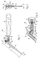
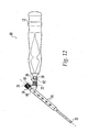
- Drill guide 10 may generally include a handle 12, a first drill guide body 14, and a second drill guide body 16. Drill guide 10 may also include a detent mechanism 18 (such as shown in detail in FIG. 6 ) and/or a locking member 20.
- First drill guide body 14 and second drill guide body 16 may be substantially tubular shafts that slide or telescope with respect to one another. According to one preferred embodiment, second drill guide body 16 may slide within first drill guide body 14 along a common longitudinal axis A1, however other configurations are possible.
- first and second drill guide bodies 14, 16 When second drill guide body 16 is received within first drill guide body 14, the first and second drill guide bodies 14, 16 preferably define a common cannula for receiving a drill bit.
- the user By holding the drill guide 10 by its handle 12 and inserting a drill bit through the cannula, the user may control the insertion point and/or the orientation of the drill bit.
- First drill guide body 14 may include a distal end 22 and second drill guide body 16 may include a proximal end 24.
- the distance X between distal end 22 and proximal end 24 may be adjusted.
- the distance X between the distal end 22 and the proximal end 24 may be adjusted to set the maximum depth to which the drill bit penetrates the bone.
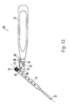
- the distal end 22 of the first drill guide body 14 may be placed substantially adjacent the bone, and drill bit 100 may be inserted into the cannula in the first and second drill guide bodies 14, 16 and drilled into the bone until a fixed stop 102 (or other enlarged diameter portion) located a predetermined distance from the tip 104 of the drill bit contacts the proximal end 24 of the second drill guide body 16, at which point the first and second drill guide bodies 14, 16 prevent further penetration of the drill bit 100 into the bone.
- drill bit 100 is shown for illustrative purposed only, and that drill guide 10 may be used with any drill bit known in the art, with or without a fixed stop.
- Handle 12 may be shaped and dimensioned to fit comfortably in the user's hand and may be provided with knurling, grooves, ridges, bumps, serrations, or other known surface treatments to increase a user's grip thereon. Additionally or alternatively, handle 12 may have a rubber, silicone or other coating.
- first drill guide body 14 may comprise a substantially tubular shaft, and may have an upper portion 26 and a lower portion 28.
- Upper portion 26 may have an inner diameter D1 that is configured and dimensioned to receive, and preferably slidably receive, second drill guide body 16.
- Lower portion 28 may have an inner diameter D2 that is smaller than inner diameter D1, but is sufficient to allow the drill bit to extend therethrough.
- the inner diameter D2 of lower portion 28 may also be configured and dimensioned to receive second drill guide body 16 (e.g., inner diameter D2 may be equal to or larger than D1).
- Lower portion 28 may also have a reduced outer diameter D3 in comparison to upper portion 26.
- the reduced outer diameter D3 may facilitate minimally invasive insertion of first drill guide body 14 into the patient; and may also aid in accessing difficult to reach areas.
- the first drill guide body 14 may be received within the second drill guide body 16.
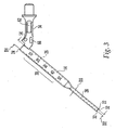
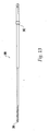
- a graduated scale 30 may be provided on first drill guide body 14, which may assist in determining the penetration depth of the drill bit, as will be discussed in more detail below.
- the graduated scale 30 may be provided on second drill guide body 16.
- Distal end 22 may have two or more projections 32 formed thereon that may engage the bone and stabilize the position of distal end 22. Projections 32 may have sharply pointed tips to ease penetration into the bone surface.
- a stem portion 34 may extend between first drill guide body 14 and handle 12, however first drill guide body 14 may alternatively be connected directly to handle 12. Handle 12 and stem portion 34 may be formed integrally, or as two separate points that are joined together. Preferably, stem portion 34 and first drill guide body 14 are formed integrally, however other configurations are possible.
- second drill guide body 16 may be connected to handle 12 in addition to, or instead of, first drill guide body 14, as will be understood by one of ordinary skill in the art from this disclosure.
- Second drill guide body 16 may comprise a substantially tubular shaft having an outer diameter D4 (shown in FIG. 4 ) that is dimensioned and configured for second drill guide body 16 to fit within first drill guide body 14.
- outer diameter D4 may be slightly smaller than the inner diameter D1 of first drill guide body 14, allowing second drill guide body 16 to slide or telescope within first drill guide body 14.
- Second drill guide body 16 may also have an inner diameter D5 (shown in FIG. 4 ) that is configured and dimensioned to receive the drill bit.
- inner diameter D5 is substantially equal to the inner diameter D2 of the lower portion 28 of first drill guide body 14, however other configurations and dimensions are possible.
- Second drill guide body 16 may have an enlarged diameter head 36 at proximal end 24, which may serve to engage a fixed stop or other feature on the drill bit or drill.
- Head 36 may also facilitate gripping by the user in order to, for example, slide or telescope second drill guide body 16 with respect to first drill guide body 14, or vice versa.
- head 36 may be provided with knurling, grooves, ridges, bumps, serrations, or other known surface treatments to increase a user's grip thereon.
- head 36 may have a rubber, silicone, or other coating.
- a lever or other mechanism may optionally be provided to cause second drill guide body 16 to slide or telescope with respect to first drill guide body 14.
- drill guide 10 may include a lever or other mechanism that a user may operate with the hand holding handle 12 to adjust the distance between distal end 22 and proximal end 24, as will be appreciated by one of ordinary skill in the art.
- second drill guide body 16 may include a peg 38 configured and dimensioned to prevent rotation of second drill guide body 16 within first drill guide body 14.
- peg 38 may fit within a track 40 defined in first drill guide body 14, such as shown in FIG. 2 .
- Peg 38, or alternatively another part of second drill guide body 16 may include a marker 42 (such shown in FIG. 5 ) that works in conjunction with the graduated scale 30 on first drill guide body 14 to indicate the penetration depth of the drill bit (based, in part, on the distance X between proximal end 22 and distal end 24 and the length of the drill bit).
- Second drill guide body 16 may also include a plurality of detents 44, such as shown in FIG. 4 .
- the detents 44 may comprise one or more angular or V-shaped indentations defined on second drill guide body 16, however other shapes and configurations are contemplated.
- detents 44 may alternatively comprise one or more protrusions defined on second drill guide body 16.
- other embodiments are contemplated where the detents 44 are associated with or defined on the first drill guide body 14.
- detents 44 may form part of a detent mechanism for releasably retaining the position of the first drill guide body 14 with respect to the second drill guide body 16 in predetermined increments.
- Peg 38 may be oriented with respect to detents 44 in order to maintain detents 44 in proper alignment with other parts of the detent mechanism.
- detents 44 are diametrically opposite peg 38, however other orientations are contemplated.
- Detent mechanism 18 may operate to releasably retain the position of the first drill guide body 14 with respect to the second drill guide body 16 in predefined increments.
- a user may adjust the first distance X (shown in FIG. 1 ; defined between the distal end 22 of first drill guide body 14 and the proximal end 24 of second drill guide body 16) in predefined, known increments.
- this may permit incremental adjustment of the maximum penetration depth of the drill bit without the use of an external measuring device. This may also permit the user to adjust the maximum penetration depth of the drill bit without having to remove the drill guide 10 from the incision in the patient.
- Graduated scale 30 may be calibrated for use with a drill bit having a predetermined length. For example, by subtracting the first distance X (between proximal end 24 and distal end 22) from the length of the drill bit, the exposed length of the drill bit may be determined. Using this convention, graduated scale 30 may be provided with markings indicating predefined maximum drill penetration depths (e.g., between 10 mm and 50 mm in 2 mm increments, or between 10 mm and 60 mm in 2 mm increments). Accordingly, graduated scale 30 and marker 42 (located on peg 38) may be read by the user to determine the maximum drill penetration depth. This may, among other things, allow the user to measure the maximum penetration depth without the use of extra measuring devices, and/or may allow the user to change the maximum penetration depth while the drill guide is still positioned inside the incision..
- predefined maximum drill penetration depths e.g., between 10 mm and 50 mm in 2 mm increments, or between 10 mm and 60 mm in 2 mm increments.
- the detent mechanism 18 may comprise a detent body 46 (shown in detail in FIG. 7 ) capable of engagement with one or more detents 44 formed on the first drill guide body 14 or the second drill guide body 16.
- detent body 46 may be slidably mounted in a bore in stem 34, however other configurations are possible.
- detent body 46 may alternatively be mounted in or on the handle 12, the first drill guide body 14, the second drill guide body 16, or any combination of these items.
- Detent body 46 may be resiliently biased into engagement with detents 44, such as by a first coil spring 48 or other known resilient member.
- Interaction between detent body 46 and detents 44 preferably releasably retains the position of the first drill guide body 14 with respect to the second drill guide body 16 unless a sufficient force is applied to the drill guide bodies 14, 16 to change their relative positions.
- a user may be required to impart sufficient force to the second drill guide body 16 (substantially along the first axis A1) in order to cause detent body 46 to move backwards against the first spring 48 sufficiently to disengage from the detent 44 and move into engagement with the adjacent detent 44. As shown in FIG.
- detent body 46 may include an angular tip 50 and/or detents 44 may have corresponding angular shapes that act as ramps to cause detent body 46 to move away from second drill guide body 16 upon sliding of the second drill guide body 16 with respect to the first drill guide body 14 along first axis A1.
- Adjacent detents 44 may be spaced apart to provide the appropriate sized increments of the maximum drill bit penetration depth. Detents 44 may also extend over a sufficient distance to provide an appropriate range of adjustment of the maximum penetration depth. For example, according to one illustrative embodiment, adjacent detents 44 may be dimensioned and configured to provide depth adjustment from 10 mm to 50 mm in 2mm increments.
- detent body 46 may also include a first pin 52 or other member extending transversely therethrough.
- First pin 52 may slide in a first elongated slot 54 (shown in FIG. 3 ) provided in stem 34 or other part of drill guide 10. Interaction between first pin 52 and first slot 54 may captivate detent body 46 on drill guide 10, even if second drill guide body 16 is completely removed from the first drill guide body 14. This may be beneficial, for example, to permit ultrasonic, steam or autoclave cleaning of the second drill guide body 16.
- Other configurations and structures for captivating detent body 46 on drill guide 10 are contemplated by the present invention, as will be readily understood by one of ordinary skill in the art from this disclosure.
- drill guide 10 may additionally or alternatively include a locking member capable of substantially preventing sliding of second drill guide body 16 with respect to first drill guide body 14.
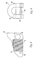
- locking member 20 shown in detail in FIGS. 8 and 9
- first position shown in FIGS. 1 and 6
- second drill guide body 16 is substantially prevented from sliding with respect to first drill guide body 14 (or vice versa) unless a user actively moves locking member 20 to a second position (not shown), for example, toward handle 12 in FIGS. 1 and 6 .
- This feature may, among other things, help prevent the first and second drill guide bodies 14, 16 from inadvertently moving or sliding with respect to one another during the drilling process.
- locking member 20 may be located on stem portion 34.
- locking member may have a substantially U-shaped cross-section (as shown in FIG. 9 ) that fits over stem portion 34, however other shapes and configurations are possible.
- a second pin 56 (shown in FIGS. 8 and 9 ) may extend between the sides 58, 60 of locking member 20 and through a second elongated slot 62 in stem portion 34.
- a third pin 64 (shown in FIGS. 8 and 9 ) may extend between the sides 58, 60 of locking member 20 and through a third elongated slot 66 in stem portion 34.
- the second and/or third pins 56, 64 may serve to secure locking member 20 on stem portion 34 so that locking member 20 can slide along stem portion 34 generally toward or away from the first and second body members 14, 16 (e.g., between the first and second positions).
- Locking member 20 may be biased towards the first position by, for example, a second coil spring 68 or other resilient member.
- coil spring 68 may be located in second elongated slot 62 and press a plunger member 70 (also located in second elongated slot 62; shown in detail in FIG. 10 ) against second pin 56 to bias locking member 20 toward the first position, however, other configurations are contemplated.
- locking member 20 When locking member 20 is in the first position, such as shown in FIGS. 1 and 6 , a portion of locking member 20 may engage detent body 46 and prevent detent body 46 from moving sufficiently to disengage the detents 44 and allow the second drill guide body 16 to move or slide with respect to the first drill guide body 14.
- locking member 20 may have one or more blocking surfaces 71 that contact or engage first pin 52 (or other part of the detent mechanism 18 or detent body 46) when locking member 20 is in the first position.
- Blocking surfaces 71 are preferably angled with respect to detent body 46 such that the forces applied by detent body 46 on blocking surfaces 71 (when detent body 46 is moved or attempted to be moved out of engagement with detents 44) results in little or no forces tending to move locking member 20 from the first position toward the second position (i.e., a low pressure angle).
- the blocking surfaces 71 move sufficiently far out of contact with first pin 52 to allow detent body 46 to move far enough out of engagement with the detents 44 such that the first and second drill guide bodies 14, 16 can incrementally slide or telescope with respect to one another.
- locking member 20 may alternatively pivot between the first position and the second position.
- locking member 20 may pivot about a pivot pin 21 that extends through stem portion 34.
- a spring biased plunger 23 or other member may bias locking member 20 into the first position (shown), in which blocking surfaces 71 engage first pin 52, to prevent detent body 46 from moving sufficiently to allow the second drill guide body 16 to move or slide with respect to the first drill guide body 14.
- the locking member 20 may be pivoted about pivot pin 21 to the second position (against the force of the spring biased plunger 23) in which position the blocking surfaces 71 are a sufficient distance from first pin 52 to allow detent body 46 to move far enough out of engagement with the detents 44 such that the first and second drill guide bodies 14, 16 can incrementally slide or telescope with respect to one another.
- locking member 20 may alternatively engage the detents 44 themselves when locking member 20 is in the first position, thereby substantially preventing movement or sliding of the first drill guide body 14 with respect to the second drill guide body 16, or vice versa.
- the locking member 20 is preferably configured and positioned so that it can be moved between the first and second positions by the thumb or finger of a hand holding the handle 12, however other configurations and positions are contemplated. As shown in FIG. 8 , locking member 20 may be provided with ridges 72 or other known surface treatments to increase a user's grip thereon, such as knurling, grooves, bumps, or serrations. Additionally or alternatively, locking member 20 may have a rubber, silicone, or other coating. Although locking member 20 is shown and described as slidably mounted to stem portion 34, other configurations and locations are contemplated. For example, locking member 20 may alternatively or additionally be mounted in, on, or associated with handle 12, first drill guide body 14, second drill guide body 16, and/or some other part of drill guide 10.
- Drill guide 10 may be used to position, orient and/or measure the depth of holes to be drilled in bone tissue, such as, for example, a vertebra. By positioning distal end 22 against the vertebra and inserting a drill bit through the first and second drill guide bodies 14, 16, drill guide 10 may be used to control the starting point of the hole to be drilled, and/or the angular orientation of the hole. Alternatively or additionally, drill guide 10 may be used to measure the depth of the hole.
- the distance between the distal end 22 and the proximal end 24 may be adjusted to determine the maximum penetration depth of the drill bit (assuming, for example, that the drill bit is inserted into the first and second drill guide bodies 14, 16 until the fixed stop or other feature engages or contacts proximal end 24).
- Detent mechanism 18 may provide incremental adjustment of the maximum penetration depth, as explained above.
- locking member 20 may prevent accidental or inadvertent adjustment of the distance between the distal end 22 and proximal end 24 during drilling or other operation.
- a user may incrementally adjust the maximum penetration depth to a known value without the necessity ofmoving drill guide 10 away from the drilling site.
- drill guide 10 may be used with other bone tissue besides the vertebrae, such as, for example, long bones.
- first drill guide body may alternatively slide or telescope within the second drill guide body; or the detent body may alternatively engage or contact the first drill guide body 14 or other portion of the drill guide. Therefore, it will be understood that the appended claims are intended to cover all such modifications and embodiments which come within the scope of the present invention.
Landscapes
- Health & Medical Sciences (AREA)
- Surgery (AREA)
- Life Sciences & Earth Sciences (AREA)
- Medical Informatics (AREA)
- Animal Behavior & Ethology (AREA)
- Orthopedic Medicine & Surgery (AREA)
- Oral & Maxillofacial Surgery (AREA)
- Engineering & Computer Science (AREA)
- Biomedical Technology (AREA)
- Heart & Thoracic Surgery (AREA)
- Dentistry (AREA)
- Molecular Biology (AREA)
- Nuclear Medicine, Radiotherapy & Molecular Imaging (AREA)
- General Health & Medical Sciences (AREA)
- Public Health (AREA)
- Veterinary Medicine (AREA)
- Surgical Instruments (AREA)
- Materials For Medical Uses (AREA)
- Dental Preparations (AREA)
- Dental Tools And Instruments Or Auxiliary Dental Instruments (AREA)
Priority Applications (1)
| Application Number | Priority Date | Filing Date | Title |
|---|---|---|---|
| PL04794913T PL1682017T3 (pl) | 2003-10-14 | 2004-10-13 | Prowadnica wiertła chirurgicznego |
Applications Claiming Priority (2)
| Application Number | Priority Date | Filing Date | Title |
|---|---|---|---|
| US10/683,000 US7131974B2 (en) | 2003-10-14 | 2003-10-14 | Surgical drill guide |
| PCT/US2004/033681 WO2005037065A2 (en) | 2003-10-14 | 2004-10-13 | Surgical drill guide |
Publications (3)
| Publication Number | Publication Date |
|---|---|
| EP1682017A2 EP1682017A2 (en) | 2006-07-26 |
| EP1682017A4 EP1682017A4 (en) | 2008-08-27 |
| EP1682017B1 true EP1682017B1 (en) | 2009-09-09 |
Family
ID=34465447
Family Applications (1)
| Application Number | Title | Priority Date | Filing Date |
|---|---|---|---|
| EP04794913A Expired - Lifetime EP1682017B1 (en) | 2003-10-14 | 2004-10-13 | Surgical drill guide |
Country Status (15)
Families Citing this family (90)
| Publication number | Priority date | Publication date | Assignee | Title |
|---|---|---|---|---|
| JP2001031134A (ja) * | 1999-07-15 | 2001-02-06 | Kimoto & Co Ltd | 生分解性フィルム及びこれを用いた生分解性袋 |
| CA113691S (en) * | 2004-01-19 | 2007-05-28 | Synthes Gmbh | Base for a surgical aiming device |
| US7406775B2 (en) * | 2004-04-22 | 2008-08-05 | Archus Orthopedics, Inc. | Implantable orthopedic device component selection instrument and methods |
| ATE524121T1 (de) * | 2004-11-24 | 2011-09-15 | Abdou Samy | Vorrichtungen zur platzierung eines orthopädischen intervertebralen implantats |
| US20090264939A9 (en) * | 2004-12-16 | 2009-10-22 | Martz Erik O | Instrument set and method for performing spinal nuclectomy |
| US7922731B2 (en) | 2006-12-22 | 2011-04-12 | Aesculap Ag | Surgical instrument and osteosynthesis device |
| US7998144B2 (en) | 2006-12-22 | 2011-08-16 | Aesculap Ag | Surgical instrument and osteosynthesis device |
| US8764841B2 (en) | 2007-03-30 | 2014-07-01 | DePuy Synthes Products, LLC | Mobile bearing assembly having a closed track |
| US8147558B2 (en) | 2007-03-30 | 2012-04-03 | Depuy Products, Inc. | Mobile bearing assembly having multiple articulation interfaces |
| US8142510B2 (en) | 2007-03-30 | 2012-03-27 | Depuy Products, Inc. | Mobile bearing assembly having a non-planar interface |
| US8328874B2 (en) | 2007-03-30 | 2012-12-11 | Depuy Products, Inc. | Mobile bearing assembly |
| US8147557B2 (en) | 2007-03-30 | 2012-04-03 | Depuy Products, Inc. | Mobile bearing insert having offset dwell point |
| US9826992B2 (en) | 2007-12-21 | 2017-11-28 | Smith & Nephew, Inc. | Multiple portal guide |
| JP5818438B2 (ja) | 2007-12-21 | 2015-11-18 | スミス アンド ネフュー インコーポレーテッドSmith & Nephew,Inc. | 多数ポータルガイド |
| US20100049198A1 (en) * | 2008-02-21 | 2010-02-25 | Tyco Healthcare Group Lp | Tibial guide for acl repair having off-axis guide wire arrangement |
| US8298239B2 (en) * | 2008-02-21 | 2012-10-30 | Tyco Healthcare Group Lp | Tibial guide for ACL repair having interchangeable and/or rotatable outrigger |
| US8323289B2 (en) * | 2008-02-21 | 2012-12-04 | Covidien Lp | Tibial guide for ACL repair having left/right docking configuration |
| US20100049199A1 (en) * | 2008-02-21 | 2010-02-25 | Tyco Healthcare Group Lp | Tibial guide for acl repair having moveable distal features |
| RU2480177C2 (ru) * | 2008-02-28 | 2013-04-27 | Т.А.Г. Медикал Девайсес - Агрикалче Кооперайтив Лтд. | Медицинское устройство и способ фиксации шва к кости |
| EP2257240B1 (en) * | 2008-03-04 | 2017-01-18 | Smith & Nephew, Inc. | A device for use during ligament reconstruction surgery |
| US20100030218A1 (en) * | 2008-08-01 | 2010-02-04 | Warsaw Orthopedic, Inc. | Surgical Instrumentation for Forming Threaded Openings in Bone |
| USD610257S1 (en) * | 2008-12-17 | 2010-02-16 | Horton Kenneth L | Surgical drill guide |
| US20100160924A1 (en) * | 2008-12-23 | 2010-06-24 | Howmedica Osteonics Corp. | Drill guide with angle verification |
| US9597095B2 (en) * | 2009-05-15 | 2017-03-21 | Globus Medical, Inc | Screw guide and tissue retractor instrument |
| US8764806B2 (en) | 2009-12-07 | 2014-07-01 | Samy Abdou | Devices and methods for minimally invasive spinal stabilization and instrumentation |
| EP2547279A1 (en) | 2010-03-18 | 2013-01-23 | Smith&Nephew, Inc. | A device for use during ligament reconstruction surgery |
| KR101110107B1 (ko) * | 2010-06-21 | 2012-01-31 | (주)오티스바이오텍 | 드릴 가이드 |
| JP5921544B2 (ja) | 2010-07-23 | 2016-05-24 | シンセス ゲゼルシャフト ミット ベシュレンクテル ハフツングSynthes Gmbh | 保護スリーブ保持機構 |
| BR112013008694A2 (pt) | 2010-09-27 | 2016-06-21 | Smith & Nephew Inc | dispositivo e métodos para uso durante cirurgia artroscópica |
| WO2012061642A1 (en) | 2010-11-03 | 2012-05-10 | Smith & Nephew, Inc | Drill guide |
| WO2012061733A1 (en) * | 2010-11-04 | 2012-05-10 | Smith & Nephew, Inc. | Drill guide depth stop |
| WO2012109594A2 (en) | 2011-02-12 | 2012-08-16 | Eca Medical Instruments | Medical tool and waste collection device |
| WO2012150989A2 (en) * | 2011-02-28 | 2012-11-08 | Eca Medical Instruments Inc. | Disposable medical drill guide |
| US8845728B1 (en) | 2011-09-23 | 2014-09-30 | Samy Abdou | Spinal fixation devices and methods of use |
| US8790352B2 (en) * | 2011-10-03 | 2014-07-29 | Smith & Nephew, Inc. | Ovoid tunnel guide and method of ACL reconstruction |
| EP2617364B1 (en) * | 2012-01-19 | 2014-06-04 | Stryker Trauma GmbH | Surgical instrument for positioning a sleeve |
| US20130226240A1 (en) | 2012-02-22 | 2013-08-29 | Samy Abdou | Spinous process fixation devices and methods of use |
| US9198767B2 (en) | 2012-08-28 | 2015-12-01 | Samy Abdou | Devices and methods for spinal stabilization and instrumentation |
| CA2885034C (en) * | 2012-09-14 | 2021-07-27 | DePuy Synthes Products, Inc. | Multihole drill sleeve with protection sleeve |
| US9320617B2 (en) | 2012-10-22 | 2016-04-26 | Cogent Spine, LLC | Devices and methods for spinal stabilization and instrumentation |
| US9801641B2 (en) | 2012-11-30 | 2017-10-31 | Ebi, Llc | Adjustable drill depth guide |
| USD779059S1 (en) | 2013-08-21 | 2017-02-14 | Eca Medical Instruments | Elongated medical instrument handle with ridges |
| US9750512B2 (en) | 2013-10-21 | 2017-09-05 | Zimmer Spine, Inc. | Drill guide for installing a bone plate |
| USD768853S1 (en) | 2013-10-23 | 2016-10-11 | Eca Medical Instruments | Medical instrument with waffle handle with bent shaft |
| EP2884767A1 (en) * | 2013-12-16 | 2015-06-17 | Oticon Medical A/S | Device for installing an implant for a bone anchored hearing aid |
| KR101502446B1 (ko) * | 2014-01-28 | 2015-03-13 | 주식회사 고영테크놀러지 | 척추용 수술기구 및 이를 채용한 수술로봇 시스템 |
| US9968373B1 (en) * | 2014-02-21 | 2018-05-15 | Surgentec, Llc | Handles for needle assemblies |
| US10188406B2 (en) * | 2014-09-25 | 2019-01-29 | David G. Matsuura | Drill depth measuring devices and methods |
| US10010333B2 (en) | 2014-09-30 | 2018-07-03 | Medos International Sàrl | Side-loading carriage for use in surgical guide |
| US10045789B2 (en) | 2014-09-30 | 2018-08-14 | Medos International Sàrl | Universal surgical guide systems and methods |
| US10098646B2 (en) | 2014-09-30 | 2018-10-16 | Medos International Sàrl | Surgical guide for use in ligament repair procedures |
| US10307173B2 (en) | 2014-09-30 | 2019-06-04 | Medos International Sàrl | Gage for limiting distal travel of drill pin |
| US10357314B2 (en) | 2015-07-08 | 2019-07-23 | Stryker European Holdings I, Llc | Instrumentation and method for repair of a bone fracture |
| CN113081155B (zh) * | 2015-09-03 | 2024-07-16 | 史赛克公司 | 带有包括可滑动的探针的一体化深度计的动力手术钻机 |
| US10857003B1 (en) | 2015-10-14 | 2020-12-08 | Samy Abdou | Devices and methods for vertebral stabilization |
| US10327787B2 (en) | 2015-12-28 | 2019-06-25 | Nuvasive, Inc | Adjustable depth drill guide |
| US10786368B2 (en) * | 2015-12-30 | 2020-09-29 | Nuvasive, Inc. | Interfixated vertebral body replacement and insertion methods |
| US10172630B2 (en) * | 2016-05-19 | 2019-01-08 | Medos International Sarl | Drill guide with adjustable stop |
| US10299847B2 (en) * | 2016-09-22 | 2019-05-28 | Globus Medical, Inc. | Systems and methods for intramedullary nail implantation |
| US10744000B1 (en) | 2016-10-25 | 2020-08-18 | Samy Abdou | Devices and methods for vertebral bone realignment |
| US10973648B1 (en) | 2016-10-25 | 2021-04-13 | Samy Abdou | Devices and methods for vertebral bone realignment |
| KR101951227B1 (ko) * | 2017-03-24 | 2019-04-30 | 주식회사 코렌텍 | 베이스 플레이트 트라이얼 홀딩 장치 및 이를 포함하는 슬관절 임플란트 수술기구 세트 |
| US11202643B2 (en) * | 2017-06-22 | 2021-12-21 | Smith & Nephew, Inc. | Anchor delivery system |
| US10792052B2 (en) * | 2017-10-26 | 2020-10-06 | Arthrex, Inc. | Surgical drill guide |
| US11058437B2 (en) | 2018-03-29 | 2021-07-13 | Zimmer Biomet Spine, Inc. | Systems and methods for pedicle screw implantation using flexible drill bit |
| US11179248B2 (en) | 2018-10-02 | 2021-11-23 | Samy Abdou | Devices and methods for spinal implantation |
| US11298244B2 (en) | 2019-01-31 | 2022-04-12 | K2M, Inc. | Interbody implants and instrumentation |
| US11317978B2 (en) | 2019-03-22 | 2022-05-03 | Globus Medical, Inc. | System for neuronavigation registration and robotic trajectory guidance, robotic surgery, and related methods and devices |
| US11571265B2 (en) | 2019-03-22 | 2023-02-07 | Globus Medical Inc. | System for neuronavigation registration and robotic trajectory guidance, robotic surgery, and related methods and devices |
| US11806084B2 (en) | 2019-03-22 | 2023-11-07 | Globus Medical, Inc. | System for neuronavigation registration and robotic trajectory guidance, and related methods and devices |
| US11382549B2 (en) | 2019-03-22 | 2022-07-12 | Globus Medical, Inc. | System for neuronavigation registration and robotic trajectory guidance, and related methods and devices |
| US20200297357A1 (en) | 2019-03-22 | 2020-09-24 | Globus Medical, Inc. | System for neuronavigation registration and robotic trajectory guidance, robotic surgery, and related methods and devices |
| US11419616B2 (en) | 2019-03-22 | 2022-08-23 | Globus Medical, Inc. | System for neuronavigation registration and robotic trajectory guidance, robotic surgery, and related methods and devices |
| US11793558B2 (en) | 2019-08-30 | 2023-10-24 | K2M, Inc. | All in one plate holder and spring loaded awl |
| US11534307B2 (en) | 2019-09-16 | 2022-12-27 | K2M, Inc. | 3D printed cervical standalone implant |
| US11490942B2 (en) | 2019-11-05 | 2022-11-08 | DePuy Synthes Products, Inc. | Device and system for facilitating insertion of a bone treatment device |
| US11207115B2 (en) | 2019-11-21 | 2021-12-28 | DePuy Synthes Products, LLC | System and method of coupling an alignment guide to an intramedullary nail insertion handle |
| EP3827760B1 (en) * | 2019-11-26 | 2024-08-07 | Globus Medical, Inc. | System for neuronavigation registration and robotic trajectory guidance, robotic surgery, and related devices |
| WO2021202123A1 (en) | 2020-03-30 | 2021-10-07 | Responsive Arthroscopy, LLC | Suture based clamping device |
| US20210369290A1 (en) * | 2020-05-26 | 2021-12-02 | Globus Medical, Inc. | Navigated drill guide |
| IT202000013591A1 (it) * | 2020-06-08 | 2021-12-08 | Limacorporate Spa | Fresa perfezionata per impiego ortopedico, in particolare nella chirurgia del ginocchio, del bacino o della caviglia |
| KR102466883B1 (ko) * | 2020-07-09 | 2022-11-16 | 주식회사 제일메디칼코퍼레이션 | 수술용 조준기구 |
| KR102392064B1 (ko) * | 2020-08-06 | 2022-04-29 | 주식회사 에스메디온 | 척추내시경 수술용 인공보형물 삽입 가이드 장치 |
| US11529147B2 (en) | 2020-08-07 | 2022-12-20 | Mighty Oak Medical, Inc. | Drilling depth and control apparatus and methods for using the same |
| US11918235B1 (en) * | 2020-09-03 | 2024-03-05 | Smith & Nephew, Inc. | Tissue protection sleeve |
| US12011199B2 (en) | 2020-10-15 | 2024-06-18 | DePuy Synthes Products, Inc. | Bone plate, bone plate system, and method of using the same |
| US11806029B2 (en) | 2021-01-06 | 2023-11-07 | DePuy Synthes Products, Inc. | Locking trocar and method of using the same |
| WO2023044295A1 (en) * | 2021-09-14 | 2023-03-23 | Responsive Arthroscopy, LLC | Improved push-in suture anchor system |
| US12082828B2 (en) * | 2021-10-13 | 2024-09-10 | DePuy Synthes Products, Inc. | Combination drill guide and depth gauge surgical instrument for implanting an acetabular cup component and associated surgical method |
| CN115844482B (zh) * | 2022-12-17 | 2023-08-29 | 尤尼泰科(重庆)医疗科技有限公司 | 长度可调快换骨科导向器 |
Family Cites Families (96)
| Publication number | Priority date | Publication date | Assignee | Title |
|---|---|---|---|---|
| US169075A (en) | 1875-10-26 | Improvement in bit-gages | ||
| US413178A (en) | 1889-10-22 | Combined scratch and bit gage | ||
| US125642A (en) | 1872-04-09 | Improvement in bit-braces | ||
| US232851A (en) | 1880-10-05 | Boring-bit gage | ||
| US2483060A (en) | 1945-12-19 | 1949-09-27 | Avitecnica Inc | Drill positioning mechanism |
| US2833168A (en) | 1955-08-16 | 1958-05-06 | Lloyd I Nelson | Drill depth gauge |
| US2933168A (en) * | 1957-08-23 | 1960-04-19 | William E Leibing | Deceleration controlled fuel shut-off means |
| US3216288A (en) | 1962-11-19 | 1965-11-09 | Gardner Irving | Adjustable and retractable hand reamer device |
| US3583822A (en) | 1968-10-31 | 1971-06-08 | Rockwell Mfg Co | Portable power tool |
| US3574290A (en) | 1968-12-16 | 1971-04-13 | Dresser Ind | Tool actuating device |
| US3682177A (en) | 1970-03-18 | 1972-08-08 | Acme Eng Co Inc | Cranial drilling instrument |
| DE7613952U1 (de) | 1976-05-03 | 1976-09-02 | Hilti Ag, Schaan (Liechtenstein) | Bohrmaschine mit tiefenanschlag |
| US4039266A (en) | 1976-07-19 | 1977-08-02 | Connell John W O | Combination stop collar and cutting tool |
| US4072440A (en) | 1977-03-11 | 1978-02-07 | Glover Robert L | Guide attachment for portable power drills |
| US4546859A (en) | 1977-09-27 | 1985-10-15 | American Hospital Supply Corporation | Adjustable stop for dispensing syringe |
| IT7869940A0 (it) | 1978-02-20 | 1978-12-22 | Heidelberger Druckmasch Ag | Mandrino corto per il serraggio di utensili cilindrici |
| DE2832429A1 (de) | 1978-07-24 | 1980-02-14 | Hilti Ag | Bohrmaschine mit bohrtiefenanschlag |
| US4341206A (en) | 1978-12-19 | 1982-07-27 | Synthes Ag | Device for producing a hole in a bone |
| ZA803410B (en) | 1979-06-19 | 1981-06-24 | Kango Electric Hammers Ltd | Drilling tools |
| US4281949A (en) | 1979-08-06 | 1981-08-04 | Bugarin Tony L | Combination depth gauge and level for a drill |
| US4538943A (en) | 1982-03-29 | 1985-09-03 | General Dynamics Corporation/Convair Div. | Adjustable nosepiece for a drill motor |
| DE3332968A1 (de) | 1982-09-20 | 1984-03-22 | Hans Bonaduz Bieler | Anschlag- und fuehrungsvorrichtung |
| DE3242862A1 (de) | 1982-11-19 | 1984-05-24 | Hilti Ag, Schaan | Handgeraet mit verstellbarem tiefenanschlag |
| US4681490A (en) | 1983-10-31 | 1987-07-21 | Dresser Industries, Inc. | Retraction apparatus for automatic feed drills or the like |
| US4592681A (en) | 1983-10-31 | 1986-06-03 | Dresser Industries, Inc. | Retraction apparatus for automatic feed drills or the like |
| DE8405010U1 (de) | 1984-02-18 | 1985-06-13 | Robert Bosch Gmbh, 7000 Stuttgart | Senkrechtbohrhilfe für Handbohrmaschinen oder Bohrhämmer |
| US4647260A (en) | 1984-03-15 | 1987-03-03 | Black & Decker Inc. | Depth-adjusting system for a power tool |
| US4591299A (en) | 1984-05-21 | 1986-05-27 | Dresser Industries, Inc. | Rapid feed apparatus for automatic feed drills or the like |
| US4674927A (en) | 1984-09-07 | 1987-06-23 | Lockhead Corporation | Telescoping nose piece |
| US4588334A (en) | 1984-09-07 | 1986-05-13 | Lockheed Corporation | Adjustable clocking nose piece |
| JPS61162473A (ja) * | 1985-01-14 | 1986-07-23 | 三菱電機株式会社 | エレベ−タ制御装置 |
| US4668134A (en) | 1986-01-13 | 1987-05-26 | P. V. Tool, Inc. | Apparatus for orientation of tool on workpiece |
| JPH072285B2 (ja) | 1986-02-14 | 1995-01-18 | 松下電工株式会社 | 穿孔工具用深さ設定具 |
| US4708139A (en) | 1986-02-24 | 1987-11-24 | Dunbar Iv William H | Arthroscopic drill guide |
| DE3632377A1 (de) | 1986-09-24 | 1988-03-31 | Bosch Gmbh Robert | Tiefenanschlag |
| US4710075A (en) | 1986-10-01 | 1987-12-01 | Boehringer Mannheim Corporation | Adjustable drill gauge |
| US4739751A (en) | 1986-10-03 | 1988-04-26 | Temple University | Apparatus and method for reconstructive surgery |
| US4922897A (en) | 1986-10-03 | 1990-05-08 | Temple University | Apparatus and method for reconstructive surgery |
| US4920958A (en) | 1986-11-05 | 1990-05-01 | Minnesota Mining And Manufacturing Company | Drill guide assembly |
| US4714469A (en) | 1987-02-26 | 1987-12-22 | Pfizer Hospital Products Group, Inc. | Spinal implant |
| JPS63267107A (ja) | 1987-04-24 | 1988-11-04 | Masamichi Nagano | 万力式電動ドリル |
| DE8800197U1 (de) | 1988-01-11 | 1988-06-23 | List, Heinz-Jürgen, 61231 Bad Nauheim | Chirurgisches Bohrwerkzeug |
| US5071293A (en) | 1989-10-30 | 1991-12-10 | Mcdonnell Douglas Corporation | Feed rate regulator for a hand-held drill |
| US5180388A (en) | 1990-06-28 | 1993-01-19 | American Cyanamid Company | Bone pinning system |
| US5133720A (en) | 1990-07-13 | 1992-07-28 | Greenberg Alex M | Surgical drill guide and retractor |
| US5026376A (en) | 1990-07-13 | 1991-06-25 | Greenberg Alex M | Surgical drill guide and retractor |
| US5743916A (en) | 1990-07-13 | 1998-04-28 | Human Factors Industrial Design, Inc. | Drill guide with removable ferrules |
| US6019767A (en) | 1990-07-16 | 2000-02-01 | Arthrotek | Tibial guide |
| US5054968A (en) | 1990-10-18 | 1991-10-08 | Dresser Industries, Inc. | Mechanical positive feed drill with supported spindle |
| US5112337A (en) | 1991-02-05 | 1992-05-12 | Depuy Du Pont Orthopaedics | Variable angle, selective length tibial drill guide |
| US5163940A (en) | 1991-03-04 | 1992-11-17 | American Cyanamid Company | Surgical drill guide for tibia |
| US5478341A (en) | 1991-12-23 | 1995-12-26 | Zimmer, Inc. | Ratchet lock for an intramedullary nail locking bolt |
| US5154720A (en) | 1992-02-19 | 1992-10-13 | Linvatec Corporation | Surgical drill guide |
| US5350383A (en) | 1992-02-20 | 1994-09-27 | Arthrex, Inc. | Adjustable drill guide with interchangeable marking hooks |
| US5562664A (en) | 1992-02-20 | 1996-10-08 | Arthrex Inc. | Drill guide with target PCL-oriented marking hook |
| SE470177B (sv) | 1992-03-23 | 1993-11-29 | Radi Medical Systems | Anordning för håltagning i hård vävnad och punktionsnål |
| US5350380A (en) | 1993-01-15 | 1994-09-27 | Depuy Inc. | Method for securing a ligament replacement in a bone |
| US5354300A (en) | 1993-01-15 | 1994-10-11 | Depuy Inc. | Drill guide apparatus for installing a transverse pin |
| US5380132A (en) | 1993-09-10 | 1995-01-10 | Black & Decker Inc. | Depth adjusting system for a power tool |
| US5330468A (en) | 1993-10-12 | 1994-07-19 | Burkhart Stephen S | Drill guide device for arthroscopic surgery |
| US5382120A (en) | 1993-12-27 | 1995-01-17 | Parsons; Richard E. | Drill bit depth minder |
| US5458602A (en) | 1994-01-11 | 1995-10-17 | Mitek Surgical Products, Inc. | Surgical drill guide |
| USD359557S (en) | 1994-02-09 | 1995-06-20 | Zimmer, Inc. | Orthopaedic drill guide |
| GB2288757B (en) | 1994-04-19 | 1997-08-06 | Black & Decker Inc | An adjustable depth-stop mechanism |
| DE19510372C1 (de) * | 1995-03-22 | 1996-07-25 | Aesculap Ag | Bohrlehre für chirurgische Bohrwerkzeuge |
| SE9501829D0 (sv) * | 1995-05-17 | 1995-05-17 | Astra Ab | Drill guide |
| US5601387A (en) | 1995-06-07 | 1997-02-11 | Black & Decker Inc. | Depth adjusting system for a power tool |
| US5613971A (en) | 1995-08-11 | 1997-03-25 | Depuy Inc. | Ratcheting tibial and femoral guide |
| US5681333A (en) | 1995-11-08 | 1997-10-28 | Arthrex, Inc. | Method and apparatus for arthroscopic rotator cuff repair utilizing bone tunnels for suture attachment |
| US5746552A (en) | 1996-03-25 | 1998-05-05 | Tsui; Gary | Adjustable drill bushing |
| US5829931A (en) | 1996-08-09 | 1998-11-03 | S-B Power Tool Company | Removable depth guide for rotary cutting tool |
| US5891150A (en) | 1996-12-04 | 1999-04-06 | Chan; Kwan-Ho | Apparatus and method for fixing a ligament in a bone tunnel |
| US5810828A (en) | 1997-02-13 | 1998-09-22 | Mednext, Inc. | Adjustable depth drill guide |
| EP0915680B1 (de) | 1997-04-25 | 2002-10-23 | Sulzer Orthopädie AG | Vorrichtung zur herstellung von endochondralen oder osteochondralen bohrungen |
| US5895389A (en) * | 1997-05-29 | 1999-04-20 | Synthes (U.S.A.) | Drilling guide and measuring instrumentation |
| US6120511A (en) | 1997-11-18 | 2000-09-19 | Chan; Kwan-Ho | Drill guide assembly and method for producing a bone tunnel |
| US5968050A (en) | 1997-12-05 | 1999-10-19 | Smith & Nephew, Inc. | Positioning a tibial tunnel |
| DE19831568A1 (de) | 1998-07-14 | 2000-01-20 | Kaltenbach & Voigt | Handstück für ärztliche oder zahnärztliche Zwecke mit einer einstellbaren Anschlagvorrichtung |
| US6162226A (en) | 1998-09-25 | 2000-12-19 | Depuy Orthopaedics, Inc. | Long bone reamer with depth stop indicator |
| US5941884A (en) | 1998-10-09 | 1999-08-24 | Osteonics Corp. | Patella preparation apparatus and method |
| US6514258B1 (en) | 1998-11-04 | 2003-02-04 | Implant Innovations, Inc. | Penetration limiting stop elements for a drill bit used for bone tissue |
| DE19916114A1 (de) | 1999-04-09 | 2000-10-12 | Kaltenbach & Voigt | Einstellehre zum Einstellen eines Tiefenanschlags an einem Handstück für medizinische Zwecke |
| US6520509B1 (en) | 1999-08-13 | 2003-02-18 | Maxtech Manufacturing Inc. | Screw guide device with drill bit/screw bit and counter sink/drill stop means |
| US6251111B1 (en) * | 1999-10-20 | 2001-06-26 | Sdgi Holdings, Inc. | Jack for pulling a vertebral anchor |
| DE10006042B4 (de) | 2000-02-10 | 2020-01-09 | Robert Bosch Gmbh | Handwerkzeugmaschine mit Tiefenanschlag |
| US6210415B1 (en) | 2000-02-18 | 2001-04-03 | Lab Engineering & Manufacturing, Inc. | Surgical drill guide |
| US6342057B1 (en) | 2000-04-28 | 2002-01-29 | Synthes (Usa) | Remotely aligned surgical drill guide |
| US6375658B1 (en) | 2000-04-28 | 2002-04-23 | Smith & Nephew, Inc. | Cartilage grafting |
| US6379364B1 (en) | 2000-04-28 | 2002-04-30 | Synthes (Usa) | Dual drill guide for a locking bone plate |
| US6443676B1 (en) | 2000-07-11 | 2002-09-03 | Roto Zip Tool Corporation | Automatic locking depth guide for cutting tools and the like |
| US6436103B1 (en) | 2000-12-21 | 2002-08-20 | Loubert Suddaby | Drill guide and plate attachment mechanism for orthopedic plating |
| US6929647B2 (en) * | 2001-02-21 | 2005-08-16 | Howmedica Osteonics Corp. | Instrumentation and method for implant insertion |
| US6447221B1 (en) | 2001-03-05 | 2002-09-10 | Mei-Tung Chen | Structure of drilling machine |
| US6758116B2 (en) | 2001-06-28 | 2004-07-06 | Porter-Cable/Delta | Depth adjusting system for a screw gun |
| DE10146452B4 (de) | 2001-09-20 | 2004-01-15 | Richard Wolf Gmbh | Zielgerät |
| US20030233098A1 (en) * | 2002-06-18 | 2003-12-18 | Stryker Spine | Variable depth drill guide |
-
2003
- 2003-10-14 US US10/683,000 patent/US7131974B2/en not_active Expired - Lifetime
-
2004
- 2004-10-13 ZA ZA200603078A patent/ZA200603078B/en unknown
- 2004-10-13 JP JP2006535604A patent/JP2007508117A/ja active Pending
- 2004-10-13 AU AU2004281735A patent/AU2004281735B2/en not_active Ceased
- 2004-10-13 WO PCT/US2004/033681 patent/WO2005037065A2/en active Application Filing
- 2004-10-13 PL PL04794913T patent/PL1682017T3/pl unknown
- 2004-10-13 BR BRPI0415419-3A patent/BRPI0415419A/pt not_active IP Right Cessation
- 2004-10-13 NZ NZ546944A patent/NZ546944A/en unknown
- 2004-10-13 EP EP04794913A patent/EP1682017B1/en not_active Expired - Lifetime
- 2004-10-13 CA CA002542603A patent/CA2542603A1/en not_active Abandoned
- 2004-10-13 CN CN2004800373213A patent/CN1893881B/zh not_active Expired - Fee Related
- 2004-10-13 ES ES04794913T patent/ES2333435T3/es not_active Expired - Lifetime
- 2004-10-13 KR KR1020067009200A patent/KR20060135633A/ko not_active Ceased
- 2004-10-13 DE DE602004023108T patent/DE602004023108D1/de not_active Expired - Lifetime
- 2004-10-13 AT AT04794913T patent/ATE442091T1/de not_active IP Right Cessation
Also Published As
| Publication number | Publication date |
|---|---|
| CN1893881A (zh) | 2007-01-10 |
| CA2542603A1 (en) | 2005-04-28 |
| AU2004281735B2 (en) | 2010-05-27 |
| WO2005037065A2 (en) | 2005-04-28 |
| DE602004023108D1 (de) | 2009-10-22 |
| EP1682017A2 (en) | 2006-07-26 |
| NZ546944A (en) | 2009-04-30 |
| KR20060135633A (ko) | 2006-12-29 |
| US20050119663A1 (en) | 2005-06-02 |
| US7131974B2 (en) | 2006-11-07 |
| PL1682017T3 (pl) | 2010-02-26 |
| AU2004281735A1 (en) | 2005-04-28 |
| BRPI0415419A (pt) | 2006-12-05 |
| ZA200603078B (en) | 2007-06-27 |
| EP1682017A4 (en) | 2008-08-27 |
| WO2005037065A3 (en) | 2005-11-24 |
| CN1893881B (zh) | 2010-04-21 |
| ATE442091T1 (de) | 2009-09-15 |
| ES2333435T3 (es) | 2010-02-22 |
| JP2007508117A (ja) | 2007-04-05 |
Similar Documents
| Publication | Publication Date | Title |
|---|---|---|
| EP1682017B1 (en) | Surgical drill guide | |
| US10945744B2 (en) | Drill guide with adjustable stop | |
| AU2003204795B2 (en) | Variable depth drill guide | |
| KR102193250B1 (ko) | 보호 슬리브를 구비한 다중구멍 드릴 슬리브 | |
| EP2332474B1 (en) | Cervical bone preparation tool and implant guide systems | |
| US5665092A (en) | Marker for surgical procedures | |
| US6379364B1 (en) | Dual drill guide for a locking bone plate | |
| US12369927B2 (en) | Adjustable drilling device and a method for use thereof | |
| US20120197263A1 (en) | Instrument Set for Screwing an Implant Into an Intervertebral Disc Space | |
| US20240252215A1 (en) | Targeting and insertion instrument for orthopedic implants |
Legal Events
| Date | Code | Title | Description |
|---|---|---|---|
| PUAI | Public reference made under article 153(3) epc to a published international application that has entered the european phase |
Free format text: ORIGINAL CODE: 0009012 |
|
| 17P | Request for examination filed |
Effective date: 20060524 |
|
| AK | Designated contracting states |
Kind code of ref document: A2 Designated state(s): AT BE BG CH CY CZ DE DK EE ES FI FR GB GR HU IE IT LI LU MC NL PL PT RO SE SI SK TR |
|
| RAP1 | Party data changed (applicant data changed or rights of an application transferred) |
Owner name: SYNTHES GMBH |
|
| RIN1 | Information on inventor provided before grant (corrected) |
Inventor name: BERGER, ROGER Inventor name: WALTHER, MARTIN Inventor name: KEYER, THOMAS, R. Inventor name: KEPHART, DOUGLAS, S. |
|
| DAX | Request for extension of the european patent (deleted) | ||
| A4 | Supplementary search report drawn up and despatched |
Effective date: 20080725 |
|
| RIC1 | Information provided on ipc code assigned before grant |
Ipc: A61B 17/17 20060101AFI20080721BHEP |
|
| 17Q | First examination report despatched |
Effective date: 20081010 |
|
| GRAP | Despatch of communication of intention to grant a patent |
Free format text: ORIGINAL CODE: EPIDOSNIGR1 |
|
| GRAS | Grant fee paid |
Free format text: ORIGINAL CODE: EPIDOSNIGR3 |
|
| GRAA | (expected) grant |
Free format text: ORIGINAL CODE: 0009210 |
|
| AK | Designated contracting states |
Kind code of ref document: B1 Designated state(s): AT BE BG CH CY CZ DE DK EE ES FI FR GB GR HU IE IT LI LU MC NL PL PT RO SE SI SK TR |
|
| REG | Reference to a national code |
Ref country code: GB Ref legal event code: FG4D |
|
| REG | Reference to a national code |
Ref country code: CH Ref legal event code: EP |
|
| REG | Reference to a national code |
Ref country code: IE Ref legal event code: FG4D |
|
| REF | Corresponds to: |
Ref document number: 602004023108 Country of ref document: DE Date of ref document: 20091022 Kind code of ref document: P |
|
| REG | Reference to a national code |
Ref country code: SE Ref legal event code: TRGR |
|
| PG25 | Lapsed in a contracting state [announced via postgrant information from national office to epo] |
Ref country code: FI Free format text: LAPSE BECAUSE OF FAILURE TO SUBMIT A TRANSLATION OF THE DESCRIPTION OR TO PAY THE FEE WITHIN THE PRESCRIBED TIME-LIMIT Effective date: 20090909 |
|
| PGFP | Annual fee paid to national office [announced via postgrant information from national office to epo] |
Ref country code: AT Payment date: 20091013 Year of fee payment: 6 Ref country code: ES Payment date: 20091117 Year of fee payment: 6 |
|
| NLV1 | Nl: lapsed or annulled due to failure to fulfill the requirements of art. 29p and 29m of the patents act | ||
| REG | Reference to a national code |
Ref country code: ES Ref legal event code: FG2A Ref document number: 2333435 Country of ref document: ES Kind code of ref document: T3 |
|
| PG25 | Lapsed in a contracting state [announced via postgrant information from national office to epo] |
Ref country code: SI Free format text: LAPSE BECAUSE OF FAILURE TO SUBMIT A TRANSLATION OF THE DESCRIPTION OR TO PAY THE FEE WITHIN THE PRESCRIBED TIME-LIMIT Effective date: 20090909 Ref country code: NL Free format text: LAPSE BECAUSE OF FAILURE TO SUBMIT A TRANSLATION OF THE DESCRIPTION OR TO PAY THE FEE WITHIN THE PRESCRIBED TIME-LIMIT Effective date: 20090909 |
|
| REG | Reference to a national code |
Ref country code: PL Ref legal event code: T3 |
|
| PG25 | Lapsed in a contracting state [announced via postgrant information from national office to epo] |
Ref country code: CY Free format text: LAPSE BECAUSE OF FAILURE TO SUBMIT A TRANSLATION OF THE DESCRIPTION OR TO PAY THE FEE WITHIN THE PRESCRIBED TIME-LIMIT Effective date: 20090909 |
|
| PG25 | Lapsed in a contracting state [announced via postgrant information from national office to epo] |
Ref country code: CZ Free format text: LAPSE BECAUSE OF FAILURE TO SUBMIT A TRANSLATION OF THE DESCRIPTION OR TO PAY THE FEE WITHIN THE PRESCRIBED TIME-LIMIT Effective date: 20090909 Ref country code: PT Free format text: LAPSE BECAUSE OF FAILURE TO SUBMIT A TRANSLATION OF THE DESCRIPTION OR TO PAY THE FEE WITHIN THE PRESCRIBED TIME-LIMIT Effective date: 20100111 Ref country code: EE Free format text: LAPSE BECAUSE OF FAILURE TO SUBMIT A TRANSLATION OF THE DESCRIPTION OR TO PAY THE FEE WITHIN THE PRESCRIBED TIME-LIMIT Effective date: 20090909 Ref country code: RO Free format text: LAPSE BECAUSE OF FAILURE TO SUBMIT A TRANSLATION OF THE DESCRIPTION OR TO PAY THE FEE WITHIN THE PRESCRIBED TIME-LIMIT Effective date: 20090909 |
|
| PGFP | Annual fee paid to national office [announced via postgrant information from national office to epo] |
Ref country code: HU Payment date: 20091009 Year of fee payment: 6 |
|
| REG | Reference to a national code |
Ref country code: HU Ref legal event code: AG4A Ref document number: E007125 Country of ref document: HU |
|
| PG25 | Lapsed in a contracting state [announced via postgrant information from national office to epo] |
Ref country code: SK Free format text: LAPSE BECAUSE OF FAILURE TO SUBMIT A TRANSLATION OF THE DESCRIPTION OR TO PAY THE FEE WITHIN THE PRESCRIBED TIME-LIMIT Effective date: 20090909 Ref country code: MC Free format text: LAPSE BECAUSE OF NON-PAYMENT OF DUE FEES Effective date: 20091031 |
|
| PGFP | Annual fee paid to national office [announced via postgrant information from national office to epo] |
Ref country code: PL Payment date: 20090930 Year of fee payment: 6 |
|
| PG25 | Lapsed in a contracting state [announced via postgrant information from national office to epo] |
Ref country code: BE Free format text: LAPSE BECAUSE OF FAILURE TO SUBMIT A TRANSLATION OF THE DESCRIPTION OR TO PAY THE FEE WITHIN THE PRESCRIBED TIME-LIMIT Effective date: 20090909 |
|
| PLBE | No opposition filed within time limit |
Free format text: ORIGINAL CODE: 0009261 |
|
| STAA | Information on the status of an ep patent application or granted ep patent |
Free format text: STATUS: NO OPPOSITION FILED WITHIN TIME LIMIT |
|
| PG25 | Lapsed in a contracting state [announced via postgrant information from national office to epo] |
Ref country code: DK Free format text: LAPSE BECAUSE OF FAILURE TO SUBMIT A TRANSLATION OF THE DESCRIPTION OR TO PAY THE FEE WITHIN THE PRESCRIBED TIME-LIMIT Effective date: 20090909 |
|
| 26N | No opposition filed |
Effective date: 20100610 |
|
| PG25 | Lapsed in a contracting state [announced via postgrant information from national office to epo] |
Ref country code: IE Free format text: LAPSE BECAUSE OF NON-PAYMENT OF DUE FEES Effective date: 20091013 Ref country code: GR Free format text: LAPSE BECAUSE OF FAILURE TO SUBMIT A TRANSLATION OF THE DESCRIPTION OR TO PAY THE FEE WITHIN THE PRESCRIBED TIME-LIMIT Effective date: 20091210 |
|
| PGFP | Annual fee paid to national office [announced via postgrant information from national office to epo] |
Ref country code: FR Payment date: 20101020 Year of fee payment: 7 |
|
| PGFP | Annual fee paid to national office [announced via postgrant information from national office to epo] |
Ref country code: CH Payment date: 20101012 Year of fee payment: 7 Ref country code: DE Payment date: 20101006 Year of fee payment: 7 |
|
| PG25 | Lapsed in a contracting state [announced via postgrant information from national office to epo] |
Ref country code: BG Free format text: LAPSE BECAUSE OF FAILURE TO SUBMIT A TRANSLATION OF THE DESCRIPTION OR TO PAY THE FEE WITHIN THE PRESCRIBED TIME-LIMIT Effective date: 20091031 |
|
| PGFP | Annual fee paid to national office [announced via postgrant information from national office to epo] |
Ref country code: IT Payment date: 20101020 Year of fee payment: 7 Ref country code: GB Payment date: 20101013 Year of fee payment: 7 |
|
| PG25 | Lapsed in a contracting state [announced via postgrant information from national office to epo] |
Ref country code: LU Free format text: LAPSE BECAUSE OF NON-PAYMENT OF DUE FEES Effective date: 20091013 |
|
| PG25 | Lapsed in a contracting state [announced via postgrant information from national office to epo] |
Ref country code: HU Free format text: LAPSE BECAUSE OF NON-PAYMENT OF DUE FEES Effective date: 20101014 |
|
| PG25 | Lapsed in a contracting state [announced via postgrant information from national office to epo] |
Ref country code: AT Free format text: LAPSE BECAUSE OF NON-PAYMENT OF DUE FEES Effective date: 20101013 Ref country code: TR Free format text: LAPSE BECAUSE OF FAILURE TO SUBMIT A TRANSLATION OF THE DESCRIPTION OR TO PAY THE FEE WITHIN THE PRESCRIBED TIME-LIMIT Effective date: 20090909 |
|
| PG25 | Lapsed in a contracting state [announced via postgrant information from national office to epo] |
Ref country code: SE Free format text: LAPSE BECAUSE OF NON-PAYMENT OF DUE FEES Effective date: 20101014 |
|
| REG | Reference to a national code |
Ref country code: ES Ref legal event code: FD2A Effective date: 20111118 |
|
| PG25 | Lapsed in a contracting state [announced via postgrant information from national office to epo] |
Ref country code: ES Free format text: LAPSE BECAUSE OF NON-PAYMENT OF DUE FEES Effective date: 20101014 |
|
| PG25 | Lapsed in a contracting state [announced via postgrant information from national office to epo] |
Ref country code: PL Free format text: LAPSE BECAUSE OF NON-PAYMENT OF DUE FEES Effective date: 20101013 |
|
| REG | Reference to a national code |
Ref country code: PL Ref legal event code: LAPE |
|
| REG | Reference to a national code |
Ref country code: CH Ref legal event code: PL |
|
| GBPC | Gb: european patent ceased through non-payment of renewal fee |
Effective date: 20111013 |
|
| REG | Reference to a national code |
Ref country code: FR Ref legal event code: ST Effective date: 20120629 |
|
| PG25 | Lapsed in a contracting state [announced via postgrant information from national office to epo] |
Ref country code: CH Free format text: LAPSE BECAUSE OF NON-PAYMENT OF DUE FEES Effective date: 20111031 Ref country code: LI Free format text: LAPSE BECAUSE OF NON-PAYMENT OF DUE FEES Effective date: 20111031 Ref country code: DE Free format text: LAPSE BECAUSE OF NON-PAYMENT OF DUE FEES Effective date: 20120501 |
|
| REG | Reference to a national code |
Ref country code: DE Ref legal event code: R119 Ref document number: 602004023108 Country of ref document: DE Effective date: 20120501 |
|
| PG25 | Lapsed in a contracting state [announced via postgrant information from national office to epo] |
Ref country code: FR Free format text: LAPSE BECAUSE OF NON-PAYMENT OF DUE FEES Effective date: 20111102 Ref country code: IT Free format text: LAPSE BECAUSE OF NON-PAYMENT OF DUE FEES Effective date: 20111013 Ref country code: GB Free format text: LAPSE BECAUSE OF NON-PAYMENT OF DUE FEES Effective date: 20111013 |
|
| PGFP | Annual fee paid to national office [announced via postgrant information from national office to epo] |
Ref country code: SE Payment date: 20091031 Year of fee payment: 6 |