EP1674635A2 - Trolley - Google Patents
Trolley Download PDFInfo
- Publication number
- EP1674635A2 EP1674635A2 EP05021478A EP05021478A EP1674635A2 EP 1674635 A2 EP1674635 A2 EP 1674635A2 EP 05021478 A EP05021478 A EP 05021478A EP 05021478 A EP05021478 A EP 05021478A EP 1674635 A2 EP1674635 A2 EP 1674635A2
- Authority
- EP
- European Patent Office
- Prior art keywords
- guide
- carriage
- receiving element
- receiving
- guide rail
- Prior art date
- Legal status (The legal status is an assumption and is not a legal conclusion. Google has not performed a legal analysis and makes no representation as to the accuracy of the status listed.)
- Withdrawn
Links
Images



Classifications
-
- E—FIXED CONSTRUCTIONS
- E04—BUILDING
- E04F—FINISHING WORK ON BUILDINGS, e.g. STAIRS, FLOORS
- E04F10/00—Sunshades, e.g. Florentine blinds or jalousies; Outside screens; Awnings or baldachins
- E04F10/02—Sunshades, e.g. Florentine blinds or jalousies; Outside screens; Awnings or baldachins of flexible canopy materials, e.g. canvas ; Baldachins
- E04F10/06—Sunshades, e.g. Florentine blinds or jalousies; Outside screens; Awnings or baldachins of flexible canopy materials, e.g. canvas ; Baldachins comprising a roller-blind with means for holding the end away from a building
- E04F10/0607—Sunshades, e.g. Florentine blinds or jalousies; Outside screens; Awnings or baldachins of flexible canopy materials, e.g. canvas ; Baldachins comprising a roller-blind with means for holding the end away from a building with guiding-sections for supporting the movable end of the blind
Definitions
- the invention relates to a carriage on a guide rail for receiving an extension profile, in particular the Ausfahrprofils a sunshade such as awning or the like, with a guide element, which is associated with the guide rail, and a receiving element which carries the Ausfahrprofil directly or indirectly.
- Such carriages are known from the prior art. These carriages are used in awnings, which are arranged above conservatories or the like, in which the extension profile, which deducts the cloth of a sunshade from a winding shaft, is guided with carriages on guide rails movable.
- the guide rails on which the carriages are arranged movable, are mounted directly on the underlying structure, such as a conservatory.
- the object of the invention is therefore to overcome the aforementioned disadvantages of the prior art and to further form a carriage on a guide rail for receiving an extension profile such that any deviations in the parallelism of the guide rails can be compensated.
- a carriage on a guide rail for receiving an extension profile, in particular the Ausfahrprofils a sunshade such as awning or the like, with a guide element, which is associated with the guide rail, and a receiving element which carries the Ausfahrprofil directly or indirectly, thereby characterized in that the receiving element is movable relative to the guide element.
- the carriage according to the invention is of simple construction and inexpensive to produce.
- the intermediate element in particular pivotable about an axis perpendicular to the guide rail arranged.
- the intermediate element can be arranged pivotably on the guide element and the receiving element can be arranged pivotably on the intermediate element.
- the pivot axis of intermediate element to the guide element and / or the pivot axis of the receiving element to the intermediate element is perpendicular to a plane spanned by guide rails surface.
- This compensating movements are made possible, whereby deviations of the parallelism of guide rails can be compensated, both in the case that the guide rails diverge in the extension direction as well as in the case that the guide rails converge in the extension direction.
- the intermediate element is formed telescopically.
- the receiving element is mounted displaceably directly or indirectly on the guide element.
- the receiving element may be mounted in a slot and / or a sliding guide, so that a relative movement of the receiving element is made possible to the guide element.
- the carriage on wheels.
- the carriage may be designed such that the rollers designed accordingly Engage profile sections of the guide rail and / or engage behind profile sections of the guide rail.
- the carriage can thereby be secured on the guide rail in the vertical direction both upwards and downwards.
- Figure 1 shows the carriage with a guide element 1, which is associated with a guide rail, not shown, and the receiving element 2, on which an unillustrated Ausfahrprofil can be fastened.
- the guide element 1 has on its underside rollers 3, 3 ', which engage in correspondingly shaped profile sections of the guide rail, not shown, and engage behind. On the rollers 3, 3 'of the carriage is thus mounted on the guide rail and secured in the vertical direction.
- an intermediate element 4 is arranged between the guide element 1 and the receiving element 2.
- the intermediate element 4 is arranged pivotably on the guide element 1 about the axis 5.
- the receiving element 2 in turn is pivotally mounted on the intermediate element about the axis 6. Due to the arrangement of the intermediate element. 4 between the guide member 1 and the receiving element 2, it is thus possible to generate a compensating movement by a corresponding deflection.
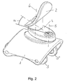
- Figure 2 shows the carriage in the pivoted position of the receiving element 2 relative to the guide element 1.
- the intermediate piece 4 is compared to the guide member 1 by the angle ⁇ pivoted out of its basic position, i. that it is pivoted by the angle ⁇ about the axis 5.
- the receiving element 2 itself is rotatably arranged on the intermediate element 4
- the connection between the receiving element 2 and the extension profile, not shown, no additional moments are impressed.
- FIG 3 shows a sunshade for placement on a building structure such as a conservatory.
- the sunscreen has a cloth shaft stored in a housing 7.
- This cloth shaft carries a cloth roll, from which the cloth whose front end is attached to the Ausfahrprofil 8, removable.
- the extension profile 8 is attached to carriage according to Figure 1 and Figure 2, which in turn are guided on guide rails 9, 10.
- the guide rails 9, 10 are not exactly parallel to each other, as these on an unillustrated, underlying winter garden, i. be mounted on the supporting profiles of the conservatory.
- the course of the guide rails during assembly must be adapted to the course of the load-bearing profiles of the conservatory for visual reasons.
- FIG. 4 Shown in Figure 4 is the detail IV of Figure 3 in an enlarged view. Shown is the winding shaft of a sunshade receiving housing 7, and the extension profile 8 of the sunshade, which is attached to the receiving element 2 of the carriage.
- the guide element 1 of the carriage is arranged on the guide rail 9, wherein the rollers 3, 3 'of the guide element 1 in corresponding tracks of the guide rail 9 run and engage behind profile sections of the guide rail 9.
- compensating movements can be realized to compensate for positional tolerances of the guide rail.
Landscapes
- Engineering & Computer Science (AREA)
- Architecture (AREA)
- Civil Engineering (AREA)
- Structural Engineering (AREA)
- Building Awnings And Sunshades (AREA)
Abstract
Laufwagen auf einer Führungsschiene (9, 10) zur Aufnahme eines Ausfahrprofils, insbesondere des Ausfahrprofils (8) eines Sonnenschutzes wie Markise o. dgl., mit einem Führungselement (1), welches der Führungsschiene (9, 10) zugeordnet ist, und einem Aufnahmeelement (2), welches das Ausfahrprofil (8) mittelbar oder unmittelbar trägt, dadurch gekennzeichnet, dass das Aufnahmeelement (2) relativ zum Führungselement (1) beweglich ist.Carriage on a guide rail (9, 10) for receiving an extension profile, in particular the Ausfahrprofils (8) of a sunshade such as awning o. The like., With a guide element (1) which is associated with the guide rail (9, 10), and a receiving element (2), which carries the Ausfahrprofil (8) indirectly or directly, characterized in that the receiving element (2) relative to the guide element (1) is movable.
Description
Die Erfindung betrifft einen Laufwagen auf einer Führungsschiene zur Aufnahme eines Ausfahrprofils, insbesondere des Ausfahrprofils eines Sonnenschutzes wie Markise oder dergleichen, mit einem Führungselement, welches der Führungsschiene zugeordnet ist, und einem Aufnahmeelement, welches das Ausfahrprofil mittelbar oder unmittelbar trägt.The invention relates to a carriage on a guide rail for receiving an extension profile, in particular the Ausfahrprofils a sunshade such as awning or the like, with a guide element, which is associated with the guide rail, and a receiving element which carries the Ausfahrprofil directly or indirectly.
Derartige Laufwagen sind aus dem Stand der Technik bekannt. Diese Laufwagen kommen zum Einsatz bei Markisen, die oberhalb von Wintergärten oder dergleichen angeordnet werden, bei denen das Ausfahrprofil, welches das Tuch eines Sonnenschutzes von einer Wickelwelle abzieht, mit Laufwagen auf Führungsschienen verfahrbar geführt ist. Die Führungsschienen, auf denen die Laufwagen verfahrbar angeordnet sind, werden dabei unmittelbar auf der darunter liegenden Baukonstruktion, beispielsweise einem Wintergarten, montiert.Such carriages are known from the prior art. These carriages are used in awnings, which are arranged above conservatories or the like, in which the extension profile, which deducts the cloth of a sunshade from a winding shaft, is guided with carriages on guide rails movable. The guide rails on which the carriages are arranged movable, are mounted directly on the underlying structure, such as a conservatory.
Nachteilig bei den bekannten Lösungen ist, dass die die Laufwagen führenden Führungsschienen exakt parallel montiert sein müssen, da Abweichungen der Parallelität der Führungsschienen nicht ausgeglichen werden können. Zu Problemen führt dies insbesondere dann, wenn die darunter liegende Baukonstruktion (Wintergarten), auf der die Führungsschienen montiert sind, ihrerseits keine exakt parallel verlaufenden Konstruktionsprofile aufweist, da wiederum eine Ausrichtung der darauf zu montierenden Führungsschienen, wenn diese nicht selbst exakt parallel zu den Konstruktionsprofilen der Baukonstruktion erfolgt, zu optischen Beeinträchtigen führt. Um derartige optische Beeinträchtigungen der Gesamtanordnung zu vermeiden, ist es erforderlich, die Führungsschienen selbst exakt parallel zu dem die jeweilige Führungsschiene tragenden Konstruktionsprofil auszurichten, wodurch wiederum eine Parallelität der Führungsschienen untereinander nicht in allen Fällen gewährleistet werden kann.A disadvantage of the known solutions that the carriages leading guide rails must be mounted exactly parallel, since deviations of the parallelism of the guide rails can not be compensated. This leads to problems in particular when the underlying building structure (conservatory), on which the guide rails are mounted, in turn, has no exactly parallel construction profiles, as in turn an orientation of the guide rails to be mounted thereon, if this does not itself exactly parallel to the construction profiles of the building construction, leads to optical impairment. In order to avoid such optical impairments of the overall arrangement, it is necessary to align the guide rails themselves exactly parallel to the respective profile guide carrying the respective guide rail, which in turn can not guarantee a parallelism of the guide rails with each other in all cases.
Aufgabe der Erfindung ist es daher, die vorgenannten Nachteile des Standes der Technik zu überwinden und einen Laufwagen auf einer Führungsschiene zur Aufnahme eines Ausfahrprofils derart weiter zu bilden, dass etwaige Abweichungen in der Parallelität der Führungsschienen ausgeglichen werden können.The object of the invention is therefore to overcome the aforementioned disadvantages of the prior art and to further form a carriage on a guide rail for receiving an extension profile such that any deviations in the parallelism of the guide rails can be compensated.
Diese Aufgabe wird erfindungsgemäß gelöst durch einen Laufwagen auf einer Führungsschiene zur Aufnahme eines Ausfahrprofils, insbesondere des Ausfahrprofils eines Sonnenschutzes wie Markise oder dergleichen, mit einem Führungselement, welches der Führungsschiene zugeordnet ist, und einem Aufnahmeelement, welches das Ausfahrprofil mittelbar oder unmittelbar trägt, der dadurch gekennzeichnet ist, dass das Aufnahmeelement relativ zum Führungselement beweglich ist.This object is achieved by a carriage on a guide rail for receiving an extension profile, in particular the Ausfahrprofils a sunshade such as awning or the like, with a guide element, which is associated with the guide rail, and a receiving element which carries the Ausfahrprofil directly or indirectly, thereby characterized in that the receiving element is movable relative to the guide element.
Dadurch das das Aufnahmelement relativ zum Führungselement beweglich ist, können Abweichungen in der Parallelität der Führungsschienen, seien diese Konstruktions- oder Montage bedingt, ausgeglichen werden. Der erfindungsgemäße Laufwagen ist dabei von einfacher Konstruktion und preiswert herstellbar.As a result of which the receiving element is movable relative to the guide element, deviations in the parallelism of the guide rails, be it due to their design or assembly, can be compensated for. The carriage according to the invention is of simple construction and inexpensive to produce.
Weitere vorteilhafte Ausgestaltungen der Erfindung sind in den Unteransprüchen angegeben.Further advantageous embodiments of the invention are specified in the subclaims.
In einer bevorzugten Ausführungsform ist zwischen dem Aufnahmeelement und dem Führungselement ein insbesondere um eine senkrecht zur Führungsschiene stehende Achse schwenkbares Zwischenelement angeordnet. Dabei kann das Zwischenelement an dem Führungselement schwenkbar angeordnet sein und das Aufnahmeelement an dem Zwischenelement schwenkbar angeordnet sein. Vorzugsweise steht die Schwenkachse von Zwischenelement zum Führungselement und/oder die Schwenkachse von Aufnahmeelement zum Zwischenelement senkrecht zu einer von Führungsschienen aufgespannten Fläche.In a preferred embodiment, between the receiving element and the guide element is an intermediate element, in particular pivotable about an axis perpendicular to the guide rail arranged. In this case, the intermediate element can be arranged pivotably on the guide element and the receiving element can be arranged pivotably on the intermediate element. Preferably, the pivot axis of intermediate element to the guide element and / or the pivot axis of the receiving element to the intermediate element is perpendicular to a plane spanned by guide rails surface.
Dadurch können Bewegungen in einer Ebene ermöglicht werden, die parallel zu einer von Führungsschienen aufgespannten Ebene liegt.This allows movements to be made in a plane parallel to a plane defined by guide rails.
Dadurch werden Ausgleichsbewegungen ermöglicht, wodurch Abweichungen der Parallelität von Führungsschienen ausgeglichen werden können, sowohl im Fall, dass die Führungsschienen in Ausfahrrichtung divergieren als auch im Fall, dass die Führungsschienen in Ausfahrrichtung konvergieren.This compensating movements are made possible, whereby deviations of the parallelism of guide rails can be compensated, both in the case that the guide rails diverge in the extension direction as well as in the case that the guide rails converge in the extension direction.
In einer bevorzugten Ausführungsform ist das Zwischenelement teleskopartig ausgebildet.In a preferred embodiment, the intermediate element is formed telescopically.
Dadurch können sehr große Ausgleichsbewegungen ermöglicht werden, die beispielsweise erforderlich sind, wenn aus architektonischen Gründen eine trapezförmige Fläche zu überspannen ist, d.h. beispielsweise bei der Anordnung eines Sonnenschutzes auf einem Wintergarten mit einer trapezförmigen Dachfläche.As a result, very large compensating movements can be made possible, which are required, for example, if a trapezoidal surface is to be spanned for architectural reasons, i. For example, in the arrangement of a sunshade on a conservatory with a trapezoidal roof surface.
Vorzugsweise ist das Aufnahmeelement unmittelbar oder mittelbar auf dem Führungselement verschieblich gelagert. Beispielsweise kann das Aufnahmeelement in einem Langloch und/oder einer Kulissenführung gelagert sein, so dass eine Relativbewegung des Aufnahmeelementes zum Führungselement ermöglicht ist. Mit dem erfindungsgemäßen Laufwagen ist somit eine Ausgleichsbewegung des Aufnahmeelementes relativ zum Führungselement möglich.Preferably, the receiving element is mounted displaceably directly or indirectly on the guide element. For example, the receiving element may be mounted in a slot and / or a sliding guide, so that a relative movement of the receiving element is made possible to the guide element. With the carriage according to the invention thus a compensating movement of the receiving element relative to the guide element is possible.
Vorzugsweise weist der Laufwagen Laufrollen auf. Dabei kann der Laufwagen derart gestaltet sein, dass die Laufrollen in entsprechend gestaltete Profilabschnitte der Führungsschiene eingreifen und/oder Profilabschnitte der Führungsschiene hintergreifen. Insbesondere kann der Laufwagen dadurch auf der Führungsschiene in senkrechter Richtung sowohl nach oben als auch nach unten gesichert werden.Preferably, the carriage on wheels. In this case, the carriage may be designed such that the rollers designed accordingly Engage profile sections of the guide rail and / or engage behind profile sections of the guide rail. In particular, the carriage can thereby be secured on the guide rail in the vertical direction both upwards and downwards.
Ein Ausführungsbeispiel des erfindungsgemäßen Laufwagens ist in den Figuren dargestellt und wird im folgenden näher erläutert.An embodiment of the carriage according to the invention is shown in the figures and will be explained in more detail below.
Es zeigen:
- Figur 1:
- Einen Laufwagen in nicht ausgelenkter Position.
- Figur 2:
- Den Laufwagen in ausgelenkter Position.
- Figur 3:
- Einen ausfahrbaren Sonnenschutz mit einem Ausfahrprofil auf Laufwagen auf Führungsschienen zur Anordnung auf einer Baukonstruktion.
- Figur 4:
- Eine vergrößerte Darstellung des Details
IV nach Figur 3.
- FIG. 1:
- A carriage in undeflected position.
- FIG. 2:
- The carriage in a deflected position.
- FIG. 3:
- An extendable sunshade with an extension profile on carriage on guide rails for placement on a building structure.
- FIG. 4:
- An enlarged view of the detail IV of Figure 3.
Figur 1 zeigt den Laufwagen mit einem Führungselement 1, welches einer nicht dargestellten Führungsschiene zugeordnet ist, und dem Aufnahmeelement 2, an dem ein nicht dargestelltes Ausfahrprofil befestigbar ist. Das Führungselement 1 weist an seiner Unterseite Rollen 3, 3' auf, die in entsprechend ausgeformte Profilabschnitte der nicht dargestellten Führungsschiene eingreifen und diese hintergreifen. Auf den Rollen 3, 3' ist der Laufwagen somit auf der Führungsschiene gelagert und in vertikaler Richtung gesichert.Figure 1 shows the carriage with a
Zwischen dem Führungselement 1 und dem Aufnahmeelement 2 ist ein Zwischenelement 4 angeordnet. Das Zwischenelement 4 ist an dem Führungselement 1 um die Achse 5 schwenkbar angeordnet. Das Aufnahmeelement 2 wiederum ist an dem Zwischenelement um die Achse 6 schwenkbar angeordnet. Durch die Anordnung des Zwischenelementes 4 zwischen dem Führungselement 1 und dem Aufnahmeelement 2 ist es somit möglich, durch eine entsprechende Auslenkung eine Ausgleichsbewegung zu erzeugen.Between the
Figur 2 zeigt den Laufwagen in ausgeschwenkter Stellung des Aufnahmeelementes 2 relativ zum Führungselement 1. Das Zwischenstück 4 ist dabei gegenüber dem Führungselement 1 um den Winkel α aus seiner Grundposition heraus geschwenkt, d.h. dass es um den Winkel α um die Achse 5 geschwenkt ist. Dadurch das das Aufnahmeelement 2 selbst wiederum drehbar auf dem Zwischenelement 4 angeordnet ist, werden der Verbindung zwischen Aufnahmeelement 2 und dem nicht dargestellten Ausfahrprofil keine zusätzlichen Momente aufgeprägt. Durch die Verschwenkung des Zwischenelementes 4 gegenüber dem Führungselement 1 wird somit eine Relativbewegung, d.h. eine Ausgleichsbewegung zwischen dem Aufnahmeelement 2 und dem Führungselement 1 ermöglicht.Figure 2 shows the carriage in the pivoted position of the receiving
Figur 3 zeigt einen Sonnenschutz zur Anordnung auf einer Baukonstruktion wie beispielsweise einem Wintergarten. Der Sonnenschutz weist eine in einem Gehäuse 7 gelagerte Tuchwelle auf. Diese Tuchwelle trägt einen Tuchwickel, von dem das Tuch, dessen vorderes Ende an dem Ausfahrprofil 8 befestigt ist, abziehbar ist. Das Ausfahrprofil 8 ist befestigt an Laufwagen gemäß Figur 1 bzw. Figur 2, die ihrerseits auf Führungsschienen 9, 10 geführt sind. Die Führungsschienen 9, 10 sind dabei nicht exakt zueinander parallel, da diese auf einem nicht dargestellten, darunter liegendem Wintergarten, d.h. an den tragenden Profilen des Wintergartens montiert werden. Dabei muss der Verlauf der Führungsschienen bei der Montage dem Verlauf der tragenden Profile des Wintergartens aus optischen Gründen angepaßt werden.Figure 3 shows a sunshade for placement on a building structure such as a conservatory. The sunscreen has a cloth shaft stored in a
In Figur 4 dargestellt ist das Detail IV nach Figur 3 in vergrößerter Darstellung. Dargestellt ist das die Wickelwelle eines Sonnenschutzes aufnehmende Gehäuse 7, sowie das Ausfahrprofil 8 des Sonnenschutzes, welches an dem Aufnahmeelement 2 des Laufwagens befestigt ist. Das Führungselement 1 des Laufwagens ist auf der Führungsschiene 9 angeordnet, wobei die Laufrollen 3, 3' des Führungselementes 1 in entsprechenden Bahnen der Führungsschiene 9 laufen und Profilabschnitte der Führungsschiene 9 hintergreifen. Über das schwenkbar am Führungselement angeordnete Zwischenelement 4, auf welchem wiederum das Aufnahmeelement 2 drehbar angeordnet ist, können Ausgleichsbewegungen zum Ausgleich von Lagetoleranzen der Führungsschiene realisiert werden.Shown in Figure 4 is the detail IV of Figure 3 in an enlarged view. Shown is the winding shaft of a
Claims (7)
Applications Claiming Priority (1)
| Application Number | Priority Date | Filing Date | Title |
|---|---|---|---|
| DE200410061975 DE102004061975A1 (en) | 2004-12-23 | 2004-12-23 | carriage |
Publications (2)
| Publication Number | Publication Date |
|---|---|
| EP1674635A2 true EP1674635A2 (en) | 2006-06-28 |
| EP1674635A3 EP1674635A3 (en) | 2014-01-08 |
Family
ID=36121482
Family Applications (1)
| Application Number | Title | Priority Date | Filing Date |
|---|---|---|---|
| EP05021478.2A Withdrawn EP1674635A3 (en) | 2004-12-23 | 2005-09-30 | Trolley |
Country Status (2)
| Country | Link |
|---|---|
| EP (1) | EP1674635A3 (en) |
| DE (1) | DE102004061975A1 (en) |
Family Cites Families (7)
| Publication number | Priority date | Publication date | Assignee | Title |
|---|---|---|---|---|
| DE8705516U1 (en) * | 1987-04-14 | 1987-07-09 | Moshacke, Werner, 8643 Küps | Awning forced guidance |
| DE4139312A1 (en) * | 1991-11-29 | 1993-06-03 | Weiermann Dieter Weinor | COVER DEVICE |
| DE19717654C2 (en) * | 1997-04-25 | 1999-05-06 | Klaus Peter Ranft | Awning bracket |
| DE10150707C5 (en) * | 2001-10-13 | 2007-11-22 | Erhardt Markisenbau Gmbh | Device for receiving a running element |
| DE10306732B4 (en) * | 2003-02-17 | 2006-04-13 | Klaus Peter Ranft | Post and beam facade with awning |
| DE10307243A1 (en) * | 2003-02-17 | 2004-08-26 | Paul Voss Gmbh & Co. Kg | shading device |
| DE10309760B4 (en) * | 2003-03-06 | 2005-04-21 | Vowisol Wintergärten GmbH | Foldable sun protection device according to the gravity principle for conservatories or the like |
-
2004
- 2004-12-23 DE DE200410061975 patent/DE102004061975A1/en not_active Withdrawn
-
2005
- 2005-09-30 EP EP05021478.2A patent/EP1674635A3/en not_active Withdrawn
Also Published As
| Publication number | Publication date |
|---|---|
| DE102004061975A1 (en) | 2006-07-06 |
| EP1674635A3 (en) | 2014-01-08 |
Similar Documents
| Publication | Publication Date | Title |
|---|---|---|
| DE2648344A1 (en) | FITTINGS FOR SLIDING WINDOWS, SLIDING DOORS, ETC. | |
| EP3354817B1 (en) | Awning with length-variable, vertical supports and lateral pusher bearing | |
| DE19717654A1 (en) | Blind for glass structure interior shading | |
| DE4402964B4 (en) | Folding arm | |
| EP2563628A1 (en) | Vehicle washing system | |
| EP4382720B1 (en) | Rail device for storing an element rail adapted to laterally guide a sun protection element for preventing sun light from entering a building | |
| DE19922586A1 (en) | Window roller blind, particularly for use in road vehicles | |
| DE102004061975A1 (en) | carriage | |
| EP3475108B1 (en) | Roller blind assembly for a vehicle body, and method for assembling the roller blind assembly | |
| DE3910647C2 (en) | Kit | |
| DE102005054488B3 (en) | Roof frame with locking device | |
| AT517283B1 (en) | Shower partition with sliding door and guide element | |
| DE10321604A1 (en) | box sleeper | |
| DE19706251C2 (en) | Awning to shade upward converging window areas | |
| DE4015995C2 (en) | Sun protection | |
| WO2005012015A1 (en) | Blind arrangement for the window of a motor vehicle | |
| DE9410724U1 (en) | Extendable shading system | |
| EP0617191B1 (en) | Guiding arrangement for greenhouse awnings or similar | |
| DE4209893C1 (en) | Closing opening in inclined roof surface - involves roof surface having outwardly pivotable roof skin casement part | |
| DE102023212093B3 (en) | Awning system | |
| DE4332177C1 (en) | Covering which can be unrolled | |
| EP3985199B1 (en) | Rail arrangement for awnings and awning equipped therewith | |
| DE102007062325A1 (en) | Roller carriage for sliding door system of motor vehicle, has supporting roller rotatably supported at base frame and horizontally supported against guiding surface of hollow profile of guide rail | |
| DE202016107143U1 (en) | Telescopic pool enclosure | |
| EP3228801B1 (en) | Vertical shading with adjustable mounting brackets |
Legal Events
| Date | Code | Title | Description |
|---|---|---|---|
| PUAI | Public reference made under article 153(3) epc to a published international application that has entered the european phase |
Free format text: ORIGINAL CODE: 0009012 |
|
| AK | Designated contracting states |
Kind code of ref document: A2 Designated state(s): AT BE BG CH CY CZ DE DK EE ES FI FR GB GR HU IE IS IT LI LT LU LV MC NL PL PT RO SE SI SK TR |
|
| AX | Request for extension of the european patent |
Extension state: AL BA HR MK YU |
|
| RAP1 | Party data changed (applicant data changed or rights of an application transferred) |
Owner name: WEINOR GMBH & CO. KG |
|
| PUAL | Search report despatched |
Free format text: ORIGINAL CODE: 0009013 |
|
| AK | Designated contracting states |
Kind code of ref document: A3 Designated state(s): AT BE BG CH CY CZ DE DK EE ES FI FR GB GR HU IE IS IT LI LT LU LV MC NL PL PT RO SE SI SK TR |
|
| AX | Request for extension of the european patent |
Extension state: AL BA HR MK YU |
|
| RIC1 | Information provided on ipc code assigned before grant |
Ipc: E04F 10/06 20060101AFI20131129BHEP |
|
| AKX | Designation fees paid |
Designated state(s): AT BE BG CH CY CZ DE DK EE ES FI FR GB GR HU IE IS IT LI LT LU LV MC NL PL PT RO SE SI SK TR |
|
| STAA | Information on the status of an ep patent application or granted ep patent |
Free format text: STATUS: THE APPLICATION IS DEEMED TO BE WITHDRAWN |
|
| 18D | Application deemed to be withdrawn |
Effective date: 20140709 |